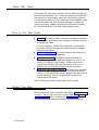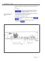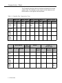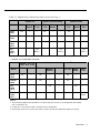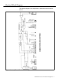
1
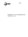
463-248-202 Issue 1 3/16/93 PagePac Plus AmpliCenter Installation and Use AT&T 463-248-202 0II722051-300 Issue 1, March 1993 Copyright 1993 Harris Dracon All Rights Reserved Written/Printed in U.S.A. Notice Every effort was made to ensure that the information in this guide was complete and accurate at the time of printing. However, information is subject to change. Federal Communications Commission (FCC) Interference Notice and Canadian Dept. of Communications This equipment has been tested and found to comply with the limits for a Class A digital device, pursuant to Part 15 of the FCC rules and D.O.C. regulations. These limits are designed to provide reasonable protection against harmful interference when the equipment is operated in a commercial environment. This equipment generates, uses, and can radiate radio frequency energy and, if not installed and used in accordance with the instruction guide, may cause harmful interference to radio communications. Operation of this equipment in a residential area is likely to clause harmful interference, in which case the user will have to correct the interference at his or her own expense. For repair information, see section 4, Maintenance and Customer Support, and for additional FCC interference and registration information, see appendix A, FCC Statement and Warranty Information, in this manual. Trademarks PAGEPAC, PAGEPAC PLUS and AMPLICENTER are trademarks of Harris Corporation. Centrex is a registered trademark of AT&T. Warranty AT&T provides a limited warranty for this product. Refer to ''AT&T Limited Warranty and Limitation of Liability" in appendix A. Ordering Information The order number for this book is 463-248-202. To order copies of this book, call 1-800-432-6600 in the U.S. and 1-800 255-1242 in Canada. For more information on how to order this and other system reference materials, see "Reference Materials," in "About This Guide." For information on ordering replacement parts, accessories, and other compatible equipment refer to "Ordering Information," in section 1. Support Telephone Numbers AT&T provides a toll-free customer Helpline 24 hours a day, In the U.S., call the AT&T Helpline at 1-800-628-2888 if you need assistance when installing, programming, or using your system. For service or technical assistance in Canada call one of the following Technical Assistance Centers: Eastern Canada and Ottawa: Ontario: Central and Western Canada 1-800-363-1882 1-800-387-4268 1-800-663-9817 VG—3193-2.2M Contents 1. ■ ■ ■ ■ ■ ■ ■ ■ ■ ■ ■ ■ ■ 2. 1-1 Overview About This Guide How to Use This Guide Before You Start Installation Steps Connectivity Chart Product Safety Labels Terminology Reference Materials How to Comment on This Guide Shipping Container Contents Ordering Information Features and Capabilities Specifications 2-1 Hardware Configuration ■ ■ ■ ■ ■ ■ 1-2 1-2 1-2 1-3 1-4 1-6 1-6 1-6 1-6 1-7 1-8 1-9 1-10 Power Circuit Protection Mounting Universal Approvals Controls and Indicators, Terminals and Connectors Auxiliary Equipment iii 2-2 2-2 2-2 2-3 2-3 2-5 3. Installing the Hardware ■ ■ ■ ■ ■ ■ ■ 4. 3-1 Important Safety Information Example System Setup Mounting PagePac Plus AmpliCenter Connecting Speakers Telephone System Interface Music Source Interface System Testing 3-2 3-3 3-6 3-8 3-9 3-11 3-13 Maintenance and Customer Support 4-1 In Case of Difficulty Power Failure Operation Common Problems Troubleshooting Electrical Block Diagram 4-2 4-3 4-3 4-3 4-5 ■ ■ ■ ■ ■ A. FCC Statement and Warranty Information A-1 B. Feedback Form B-1 IN. Index IN-1 iv Tables 1. 1-1 Overview 1-1. PagePac Plus Connectivity Chart 1-2. AmpliCenter Specifications 2. 1-4 1-10 2-1 Hardware Configuration 2-1. Controls and Indicators, Terminals and Connectors v 2-4 Figures 1. Overview 1-1 1-1. Installation Steps 1-2. AmpliCenter Components 1-3. PagePac Plus AmpliCenter 2. 1-3 1-7 1-9 Hardware Configuration 2-1 2-1. AmpliCenter Controls and Indicators, Terminals and Connectors 3. Installing the Hardware 3-1. 3-2. 3-3. 3-4. 3-5. 3-6. 3-7. 4. 2-3 3-1 AmpliCenter Interface with PagePac Plus Controller Series AmpliCenters, without Controller Wall Mounted Hardware Rack Mounted Hardware Speaker Run Method AmpliCenter Interconnection to Telephone System or to Controller Music Input Connections Maintenance and Customer Support 4-1. AmpliCenter Electrical Block Diagram vi 3-4 3-5 3-6 3-7 3-8 3-10 3-12 4-1 4-5 Overview Contents About This Guide How to Use This Guide Before You Start Installation Steps Connectivity Chart Product Safety Labels Terminology Reference Materials How to Comment on this Guide Shipping Container Contents Ordering Information Features and Capabilities Specifications 1-2 1-2 1-2 1-3 1-4 1-6 1-6 1-6 1-6 1-7 1-8 1-9 1-10 Overview 1-1 About This Guide The PagePac Plus AmpliCenter Installation and Use Manual explains the features of the AmpliCenter, how to install and configure the AmpliCenter, and interface to a communication system and other auxiliary equipment. It is intended that PagePac Plus be installed by a trained telephone, audio, or electrical installer with basic electronic knowledge. PagePac Plus conforms to common installation practices and preferences found within the Telcom Electrical and Commercial Sound installers manual. How to Use This Guide ■ Overview. This section provides an overview of AmpliCenter features and capabilities, specifications, and a summary of installation steps for the experienced installer. If you are installing the PagePac Plus AmpliCenter for the first time, you should read this entire guide before getting started to familiarize yourself with the features. ■ Hardware Configuration. This section describes and illustrates the AmpliCenter D20, D100, and D300 units. ■ Installing the Hardware. This section provides instructions for mounting the PagePac Plus AmpliCenter hardware on a wall or in a standard 19" equipment rack. Complete, detailed instructions for connection and operation with telephone systems, music source, speakers, and any control device inputs or outputs is provided. ■ Maintenance and Customer Support. This section gives some basic troubleshooting tips if a paging zone does not operate properly after connection to the AmpliCenter. Should a problem arise which requires technical assistance, call AT&T technical support groups at the numbers listed in this section. Use the Contents and Index to locate specific items of interest. Before You Start Before installing your system, read and understand the safety instructions in section 3. Be sure you have all the necessary parts— see Shipping Container Contents, below. In addition, see Tools Required in section 3 for a few tools and test equipment that will be needed for installation. 1-2 Overview Installation Steps 1. Mount the PagePac Plus AmpliCenter to either the wall, cabinet or a rack. 2. Pull cables. 3. Hookup cabling to AmpliCenter and auxiliary equipment. (Refer to Example Setups in section 3.) Use stick-on labels to identify the AmpliCenter/zone (i.e., cafeteria - zone 1). NOTE: The numbers in these steps match the numbers in figure 1-1. 4. Set the AmpliCenter Telephone Mode Selection Switch to match the host telephone system and make connection. 5. Install power cord and plug into outlet. 6. Test paging zone served by the AmpliCenter. (Refer to Testing the System, in section 3.) 7. Adjust sound levels using AmpliCenter controls. (Refer to Adjustments, in section 4.) TO HOST TEL. SYSTEM MUSIC INPUT Figure 1-1. Installation Steps Overview 1-3 Connectivity Chart The Connectivity chart gives the trunk interface requirements for the host systems listed. This information is then used to set the telephone mode function switch on the PagePac Plus AmpliCenter. Table 1-1. PagePac Plus Connectivity Chart Mode Loop Start Ground Start 3 Dry Loop (Hi Z) Dry Loop Merlin Plus C.O. Page Line Port Merlin 206/820 C.O. Page Line Module Merlin 1030/3070 C.O. Service Line Module Merlin II C.O. Analog Line Station Yes — Yes Note 1 — Yes Note 1 — Yes Note 1 — — — — — — — — — — — — — — — — — — — — — — — — — — — — — — — Yes Note 1 (600 Ω) Partner Spirit 308/616 Mode Loop Start Merlin Legend Analog C.O. Station Line Spirit 1224/2448 C.O. Line Page Port C.O. Line — Partner II Partner Plus C.O. Line Analog Station C.O. Line Analog Station Page Port Yes — Yes Yes — Yes — — Ground Start 3 — — — — — — — — Dry Loop (Hi Z) — — — — — — — — Dry Loop — No — — — — — Yes Note 2 (600 Ω ) 1-4 Overview Table 1-1. PagePac Plus Connectivity Chart (Continuation Page 1) System 25 Mode C.O. Line Analog Station System 85/G2 System 75/G1/G3I Definity Aux. Port C.O. Line Analog Station Aux. Port C.O. Line Analog Station Aux. Port Loop Start Yes — — Yes — — Yes — — Ground Start 3 Yes — — Yes — — Yes — — Dry Loop (HI Z) — — — — — — — — — Dry Loop (600 Ω) Yes Note 2 Yes Note 2 Yes Note 2 — Indicates a non applicable connection Dimension Horizon Comkey 416, 718 1434 and 2152 C.O. Line Intercom C.O. Line Analog Station Intercom C.O. Line Analog Station Aux. Port Loop Start Yes — Yes — — Yes — — Ground Start 3 — — Yes — — Yes — — Dry Loop (HI Z) — — — Yes — — Yes — Dry Loop (600 Ω) — No — — No — — Yes Note 2 Mode NOTES: 1. Two pound keys (##) must be pressed for one pound key (#) to be sent to the AmpliCenter when dialing from a multi-button set. 2. A 2 pair RJ-11 cord must be used to interface with the AmpliCenter. 3. Ground Start trunk for tel. system must share a common ground with AmpliCenter page input ground. Overview 1-5 Product Safety Labels This guide contains several product safety labels, identified by a CAUTION - Indicates the presence of a hazard that will or can cause minor personal injury or property damage if the hazard is not avoided. WARNING - Indicates the presence of a hazard that can cause severe or fatal personal injury if the hazard is not avoided. Carefully read all WARNING labels. Opening the system modules will expose you to hazardous voltages, which can cause severe personal injury or death. Also, read "Important Safety Information" at the beginning of Section 3, Installation. Terminology This guide uses standard telephony, audio, and electronics terminology used in describing paging features, hardware, and telecommunication system interface. Reference Materials For related product information, refer to the PagePac Plus Programming and Operation Guide. Also, see the PagePac Plus Controller Installation and Use Guide and Zone Expansion Unit Installation and Use Manual for specific information on those products. To order additional reference materials call the AT&T Customer Information Center: In the U.S. 1-800-432-6600 In Canada: 1-800-255-1242 How to Comment on This Guide A feedback form is located at the end of this guide. If the feedback form is missing, send your comments and recommendations for changes to: A. Sherwood AT&T 99 Jefferson Road (Room 2A-25) Parsippany, NJ 07054 FAX: (201) 887-6898 1-6 Overview Shipping Container Contents The following items should be found in the PagePac Plus AmpliCenter shipping container. ■ AmpliCenter ■ Rack ■ module mounting hardware (4 Phillips 10-32 screws) Power Cord ■ This Installation and Use guide AMPLICENTER D20, D100, D300 FOUR MOUNTING SCREWS INSTALLATION MANUAL AmpliCenter Installation and Use POWER CORD Figure 1-2. AmpliCenter Components Overview 1-7 Ordering Information Equipment is available from many AT&T sources. Contact any of the following for sales information and advice on the equipment that would best meet your needs: AT&T AT&T AT&T AT&T 1-8 Overview Catalog Sales Sales Office Phone Center Store Authorized Dealer 1-800-451-2100 1-800-247-7000 1-800-222-3111 1-800-247-1212. Features and Capabilities The following list provides an overview of the features of the PagePac Plus AmpliCenter. Amplifies paging — The AmpliCenter amplifies the page in increments of 20 watts (D20), 100 watts (D100), or 300 watts (D300) for a 70V constant voltage distribution system. Paging input — The AmpliCenter accepts inputs from PBX trunk ports, dry loop page ports, or amplified microphones. Music interface — The AmpliCenter is the unit to which the background music source (CD, radio, tape player) is connected, for distribution to the paging system. Volume control — The AmpliCenter has music ducking (mute) level, music volume level, and bass control adjustment pots on the rear panel. Overall output level can be controlled by dialing a DTMF code. Remote amplifier connection — The AmpliCenter provides 0 dBm audio output for connection to a remote amplifier, which receives a contact closure control signal from the AmpliCenter. AmpliCenter D20, D100, D300 PEC 5328-020, -100, -300 MOUNTING BRACKETS Figure 1-3. PagePac Plus AmpliCenter Overview 1-9 Specifications Table 1-2. AmpliCenter Specifications ■ D20: up to 20 Watts total speaker load ■ D100: up to 100 Watts ■ D300: up to 300 Watts Dimensions and Weights ■ All models: 3-1/2" (8.9 cm) high x 19" (48.25 cm) wide x 5" (12.7 cm) deep ■ D20: 5 lbs (11 Kg) , D100 and D300: 6 Ibs (13 Kg) RJ-11 Jack ■ Talk Capacities Specifications battery: 24 volts, loop start or ground start, negative voltage ring lead ■ Impedence: 600 Ω Temperature Range: ■ -10 to +40 deg. C. (14°F to 104°F) operational; to +50 deg. C. (122°F) with forced air ■ -20 to +70 deg. C. (28°F to 158°F) storage and shipment Humidity Range: ■ 5% Environmental Requirements ■ Locate Electrical ■ 100-250 to 95% (non-condensing) storage/shipment and operation ■ Outlet in an area free of excess moisture, corrosive gases, dust, and chemicals. VAC, 50/60 Hz, lamp, 3-prong outlet separate ground must not be controlled by an on/off switch ■ Grounding: A. Use the power cord supplied with the unit, or an equivalent cord that meets applicable safety codes. Do not cut or remove the third wire ground prong. B. The attachment-plug receptacles in the vicinity of the product or system are all to be of a grounding type, and the grounding conductors serving these receptacles are to be connected to earth ground at the service equipment. 1-10 Overview Hardware Configuration 2 Contents Power Circuit Protection Mounting Universal Approvals Controls and Indicators, Terminals and Connectors Auxiliary Equipment 2-2 2-2 2-2 2-3 2-3 2-5 Hardware Configuration 2-1 Power The rear panel of the AmpliCenter has a green LED which lights indicating Power On. One DC voltage derived from the PagePac Plus D-series AmpliCenter via the interconnect cable (provided with the Controller) is the source for all power required by the PagePac Plus Controller and any (optional) attached Zone Expansion Modules. Circuit Protection Complete thermal and short circuit protection with automatic reset. Mounting Capable of mounting into a EIA 19" cabinet, free standing rack, or wall mounting. Refer to Installation section 3. 2-2 Hardware Configuration Universal Approvals Domestic and international approvals: ■ UL813 ■ FCC, Part 15, Class A (see Appendix A) ■ CSA 22.2, No 950 ■ DOC. Controls and Indicators, Terminals and Connectors Figure 2-1 shows the controls and indicators, terminals and connectors on the rear panel of the AmpliCenter. Table 2-1 identifies them by function. Refer to the PagePac Plus Installation and Use Guide for similar information for the whole PagePac Plus system. Figure 2-1. AmpliCenter Controls and Indicators, Terminals and Connectors Hardware Configuration 2-3 The following items describe all control and indicator functions illustrated in figure 2-1: Table 2-1. Controls and Indicators, Terminals and Connectors 1. AC Power in: 100-250VAC, 50/60 Hz, 1 amp (AmpliCenter is self-switching.) 2. 0dBm out, an auxiliary output that differs from the main 70.7V output in that it is a low level (0dB), 600 ohm balanced output used for driving a remote or off-premises amplifier 3. DC Power, and 70V audio out to Controller 4. Bass control screw-type adjustment pot. Attenuates low frequencies so that horns and small speakers are not overdriven by excessive bass energy. Cut-off frequency is adjustable from 50 Hz (full CCU) to 400 Hz (full CU) 5. Music In: left and/or right channels with ground; Paging In: redundant paging input (ground, C1, tip, and ring) 70V Out: Balanced output used for terminating the loudspeaker wiring 6. Screw-type pots: VOX sensitivity level, Music ducking (mute level for music during voice page), Music level for various music sources 7. LEDs: green - power on, lights when AC line voltage is applied to AmpliCenter red – overload, lights when the AmpliCenter output exceeds its output power rating. This can occur when total speaker load is greater than the output rating, or when speaker wiring is shorted red - unbalanced output, indicates when one speaker lead is accidentally shorted to ground green – page accessed, lights when voice paging is active 8. Telephone system mode switch: dry loop 600 ohms, dry loop Hi Z, ground start, and loop start 9. From host telephone system or Controller RJ11 connector paging audio and control 2-4 Hardware Configuration Auxiliary Equipment Your PagePac Plus AmpliCenter D20, D100, or D300 is compatible with numerous peripheral products and speakers which can be utilized to meet your facility requirements ■ AT&T PagePac Plus Controller (PEC 5323-100) ■ AT&T PagePac Plus Zone Expansion Unit (PEC 5335-100) ■ Speakers — a full range of 70V speaker products is available for use with the PagePac Plus AmpliCenter -- from wall or ceiling mount speakers to horn-type speakers. ■ Amplifiers — Depending on your paging applications, several amplifiers (auxiliary) are available. These include the PagePac 6 (PEC 5323-006), a 6-watt small amplifier or the PagePac Plus AmpliCenter D20 (20 watt), D100 (100 watt), or D300 (300 watt) series AmpliCenters (PEC 5328-020, 5328-100, 5328-300) designed for larger area paging demands. ■ Microphone — The AT&T Microphones are compatible with the PagePac Plus system, including the AmpIiCenter. Microphones are available for single-zone paging (PEC 5335-400) and for multi-zone paging (PEC 5335-405) with the PagePac Plus Controller. Each microphone provides excellent audio fidelity and has an On/Off contact closure. ■ Doorspeaker — The AT&T Doorspeaker (PEC 5330-230) is compatible with the PagePac Plus system, including the AmpliCenter. This indoor/outdoor speaker can be surface or flush-mounted to a wall and provides a pushbutton for alerting inside personnel that the door needs attention. ■ PagePal — for station or C.O. access. ■ Ambient level controllers, messaging systems, feedback or speech processing units, music sources, etc. Hardware Configuration 2-5 Installing the Hardware 3 Contents Important Safety Information 3-2 ■ Additional 3-2 Safety Instructions for Installation Personnel Example System Setup 3-3 ■ AmpliCenter Interface with Controller 3-3 ■ AmpliCenter without Controller, with Series AmpliCenter(s) 3-3 Mounting PagePac Plus AmpliCenter 3-6 ■ Tools 3-6 Required Connecting Speakers Telephone System Interface Music Source Interface System Testing ■ Apply AC Power ■ Audio Paging Zones 3-8 3-9 3-12 3-13 3-13 3-13 Installing the Hardware 3-1 This section provides complete instructions for mounting the PagePac Plus AmpliCenter on a wall or in a standard EIA 19" cabinet or equipment rack. It also illustrates all interface requirements to (optional) PagePac Plus Controller, telephone systems, music source, speakers, auxiliary equipment, and any control inputs or outputs. Important Safety Information Always follow these basic safety precautions when using the system: 1. Read and understand all instructions. 2. Follow all warnings and instructions marked on the product. 3. DO NOT block or cover the ventilation slots and openings. They prevent the product from overheating. DO NOT place the product in a separate enclosure or cabinet, unless proper ventilation is provided. 4. Never spill liquid on the product or drop objects into the ventilation slots and openings. Doing so may result in serious damage to the components. 5. Repair or service must be performed by a factory authorized repair facility or AT&T technician. 6. The product is provided with a UL-CSA approved, 3-wire ground type plug. This is a safety feature. DO NOT defeat the safety purpose of the grounding type plug. DO NOT staple or otherwise attach the AC power supply cord to building surfaces. 7. DO NOT use the product near water or in a wet or damp place (such as a wet basement). 8. DO NOT use extension cords. The product must be installed within 6 feet of a grounded outlet receptacle. Additional Safety Instructions for Installation Personnel 1. DO NOT install telephone wiring during a lightning storm. 2. DO NOT install telephone jacks in a wet location unless the jack is specifically designed for wet locations. 3. Never touch uninsulated wires or terminals, unless the line has been disconnected at the paging or controller interface. 4. Use caution when installing or modifying paging or control lines. 5. The PagePac Plus AmpliCenter must be securely wall mounted or installed in a standard 19" EIA equipment rack or cabinet. CAUTION: If any wiring from the paging system leaves the building premises, you must install AT&T 503A1 IROB projectors. 3-2 Installing the Hardware Example System Setup Amplicenter Interface with Controller This example illustrated in figure 3-1 gives you a quick overview to the interconnection between the AmpliCenter and the PagePac Controller. See the PagePac Plus Controller Installation and Use manual for details on setting up any of these configurations: A traditional 70 volt installation The 70v AmpliCenter Audio Output Is Routed Via The Pagepac Plus Controller to paging zones. Make sure that the Controller has its external function mode slide switches set for proper operation (detailed in the Controller Installation and Use Guide) and is correctly programmed to configure each paging or control zone (Refer to the PagePac Plus Controller Programming and Operation Guide). Controller System In this configuration, the Controller sends 0dBm audio to the AmpliCenter(s). The AmpliCenter’s 70V output then goes directly to the speakers, without being routed through the Controller’s zone distribution relays. Each AmpliCenter’s audio will only be sent to a specific selected zone. Both remote AmpliCenters and amplified speakers can be controlled in this mode as well as other ancillary equipment requiring an audio output or a switch closure, or both. Hybrid System This method uses a combination of the two above configurations. AmpliCenter without Controller, with Series AmpliCenter(s) In this configuration (figure 3-2), the host telephone system connects directly to the first AmpliCenter unit. No PagePac Plus Controller is utilized. The first AmpliCenter passes a control signal and paging audio to the second AmpliCenter in the series. This configuration results in a one-zone paging set-up, wherein a page is broadcast to all speakers simultaneously. However, each AmpliCenter may have a different music source. (Example: rock/pop – production areas, easy listening – hallways; none – offices.) Installing the Hardware 3-3 AmpliCenter ALL MODULES POWER INPUT 100-250 VAC 50/60 HZ, 1 amp MUSIC INPUT SET TO DRY LOOP 600 OHM PAGE FROM CONTROLLER NIGHT BELL CONTROLLER ATTENDANT ACCESS INPUT TELEPHONE SYSTEM INTERFACE RS232-TO PC (OPTIONAL) INPUT OR OUTPUT ZONES: 1-8 POWER AND AUDIO TO CONTROLLER 0dBm/MPS OUTPUT Figure 3-1. AmpliCenter Interface with PagePac Plus Controller 3-4 Installing the Hardware FIRST AMPLICENTER MUSIC INPUT TO HOST TEL. SYSTEM AC POWER CONNECTION (USE EITHER MOTHOD) PAGING CONNECTION NEXT APLICENTER TO HOST TEL. SYSTEM TO SPEAKER NEXT AMPLICENTER MUSIC INPUT AC POWER CONNECTION SET TO DRY LOOP 600 Ω TO NEXT AMPLICENTER TO SPEAKERS Figure 3-2. Series AmpliCenters, without Controller Installing the Hardware 3-5 Mounting PagePac Plus AmpliCenter NOTE: Figure 3-3 illustrates a wall mounted configuration. Figure 3-4 illustrates a rack mounted arrangement. The AmpliCenter must be securely wall mounted or installed in a standard 19" EIA cabinet or free-standing equipment rack (Wall mount wood screws not provided). Tools Required The following tools are required for the installation of the system hardware and cabling. ■ Phillips screwdriver (for 10-32 screws) ■ Standard blade screwdriver (small, for terminal block connections and level adjustments) ■ Wire strippers (24 AWG -12 AWG) ■ Telephone ■ Tone test set (optional, for troubleshooting) out circuit tester (optional, for troubleshooting) ■ Portable 70V speaker (use cabling pulled for ceiling speakers) (optional, for troubleshooting) ■ Volt-Ohm ■4 Meter (optional, for troubleshooting) wood screws, if mounting on wall SIDE VIEW FRONT VIEW AMPLICENTER 6 FOOT POWER CABLE MUSIC INPUT PAGE INTO AMPLIFIER Figure 3-3. Wall Mounted Hardware 3-6 Installing the Hardware FRONT DETAIL 1.750 TYPICAL COMBINATION PAN HEAD PILOT POINT # 10-32(TYPICAL) REAR DETAIL POWER STRIP Figure 3-4. Rack Mounted Hardware Installing the Hardware 3-7 Connecting Speakers Using common industry standard procedures or accepted practices of AT&T for telephone equipment, mount speakers and adjust speaker top for each paging zone and run the appropriate cable for 70 volt speaker systems. Use class 2 wiring, and comply with any local safety codes. The speakers are wired to the AmpliCenter using either of two methods (figure 3-5). Recommended cable size is 24-22 AWG minimum for 20-watts, 18-20 AWG for 100-watts, and 16-18 AWG for 300-watts, with shielded cable for all speakers with talkback. Connect speaker wire to 70V output connector on rear of AmpliCenter unit. NOTE: If paging zones use the talkback feature, cabling must be shielded and grounded at the AmpliCenter connector, not the speaker. If there are long speaker runs, it is recommended to use a larger gauge solid wire. HOME RUN METHOD SPEAKERS TWO WIRES AMPLICENTER TWO WIRES 66-TYPE CONNECTION BLOCK TWO WIRES SPEAKER-TO-SPEAKER METHOD AMPLICENTER Figure 3-5. Speaker Run Method 3-8 Installing the Hardware SPEAKERS Telephone System Interface The AmpliCenter, when used without a PagePac Plus Controller, connects directly to your facility telephone system for paging. Figure 3-6 shows this interconnection. Be sure the Telephone Mode Switch on the rear of the AmpliCenter is set to the type of telephone system you have (see next paragraph). When used with a PagePac Plus Controller, the AmpliCenter receives its telephone paging input from the controller. Figure 3-6 illustrates this interface, as well. The connection between the AmpliCenter and the page input interface has four possible modes of operation to accommodate a variety of telephone systems. They are as follows: ■ Dry loop, 600 ohms ■ Dry loop, Hi Z ■ Ground start ■ Loop start Telephone Mode Switch 1 2 DL DL 600 HI-Z 3 GS 4 LS 1. Dry Loop 600 Ohms, used for input from paging port of PBX or from microphone 2. Dry Loop Hi Impedance, used to parallel many AmpliCenter inputs without loading down the source output. 3. Ground Start Trunk, for input direct from PBX 4. Loop Start Trunk, for input direct from PBX Installing the Hardware 3-9 The Dry Loop 600 Ohm is a four wire interface consisting of a dry audio pair with a 600 ohm impedance and a control pair. The page input is activated when the control pair receives a contact closure from the host equipment, connecting C1 to ground. The Dry Loop page input can also be activated by the presence of page input audio signals that exceed a set threshold. This threshold is set by the page VOX adjustment; clockwise rotation lowers the threshold and makes it more sensitive. Adjust by experimentation to account for various line loss and noise. This feature is beneficial for (amplified) microphone sources that don’t have a Music/Page control contact, or for remote AmpliCenters connected by leased pairs so that another pair is not required for Music/Page switching control. Dry Loop Hi Impedance is used to interface with parallel multiple inputs. Input impedance is 100K ohms. Otherwise, the same as the 600 ohm dry loop operation. NOTE: Ground start interface requires common ground between paging input and telephone system by direct line or other common grounding methods. The Ground Start mode is a two wire interface and has a 600 ohm input impedance. When a trunk is accessed, a momentary ground is sent to the ring-side of the pair by the host equipment, loop current is detected and the tip-side pair is closed. Disconnect supervision of the ground start mode is accomplished by monitoring the loop current. The Loop Start mode is two wire interface and has a 600 ohm input impedance. The host equipment draws loop current from the talk-battery which is supplied by the AmpliCenter. Disconnect supervision of the loop start mode is accomplished by monitoring the loop current. 3-10 Installing the Hardware SET TO HOST SYSTEM REQUIREMENTS NOTE: THESE TERMINALS ARE REDUNDANT PAGE INPUT CONNECTION. USEFUL WHEN A MODULAR RJ-11 PLUG AND CABLE IS NOT SUITABLE. TO HOST TELEPHONE SYSTEM OR PAGING SYSTEM CONTROLLER PBX HOST TELEPHONE SYSTEM LOOP START TRUNK PORT OR DRY LOOPO PAGE PORT Figure 3-6. AmpliCenter Interconnection to Telephone System or to Controller Connection to AmpliCenter The page input cord that connects to the PagePac Plus AmpliCenter has a standard 4-wire RJ-11 type plug or leads on the end that connects to the AmpliCenter. The other end of the cord, depending on the host system, may have a special 25-pair connector, spade-tip leads, or an RJ-11 type plug. The page input cord conductors are usually color-coded and are connected to the host system as follows. 1. Connect black wire to the paired dry contact control lead ground. 2. Connect yellow wire to the paired dry contact control lead C1. 3. Connect red wire to system ring R. 4. Connect green wire to system tip T. Installing the Hardware 3-11 Music Source Interface Music Input To provide background music for your paging system, a music source can be connected to your AmpIiCenter at the 10-position connector on the rear. The audio source can be a CD player, AM, FM, or commercial radio, tape player, or other audio device. Since most music sources are stereo, left and right channel inputs are combined in the AmpliCenter. Monophonic sources can be connected to either left or right input with the other not connected. You can adjust the music volume level, ducking level (volume of music while voice page is active) by means of volume controls on the rear of the AmpliCenter. The AmpliCenter unit amplifies and distributes the music signal to the paging zones. The PagePac Plus AmpliCenter has a screw strip connector that ties down the cabling from the music source. Refer to figure 3-7. SHIELDED CABLE OUT TO SPEAKERS FROM EXTERNAL MUSIC SOURCE Figure 3-7. Music Input Connections 3-12 lnstalling the Hardware System Testing With the zone wired and connected to the AmpliCenter, testing may begin. CAUTION: Be careful not to short out any audio output contacts during this procedure as the AmpliCenter may go into overload as indicated by the overload LED. A distorted or inaudible page will result. Apply AC Power Power to the PagePac AmpliCenter is supplied through a single power cord connected to a grounded outlet. There is no power switch. Connect the 100-250 VAC modular connector to the back of the AmpliCenter and then to the outlet socket. Do not defeat the third wire ground circuit. Audio Paging Zones Use the following steps to test audio paging zone output. 1. Adjust the Low Frequency Cut-Off control. This control attenuates low frequency bass so that horns and small speakers are not over-driven and distorted by excessive bass energy. Cut-off frequency is continuously adjustable from 50Hz (full CCW rotation) to 400 Hz (full CW rotation). 2. The Page VOX sensitivity is turned fully counter-clockwise if the Dry Loop feature is not used. 3. Adjust Music Input level. Clockwise rotation will increase the level. Listen and set to a comfortable level. 4. Using a telephone from the host system, dial the paging access code. Speak into the telephone in a normal manner. Your voice should be heard from all connected speakers. The AmpliCenter Page Input has an automatic level control (ALC) which keeps loud talker’s and normal talker’s output at the same level. Beware of paging from a telephone directly under a loudspeaker; feedback howl can occur. (An anti-feedback speech processing unit or a record/playback delay unit can solve this if it will be a problem for the users. 5. Re-adjust Music Input level to the desired loudness relative to Paging loudness. 6. Some loudspeaker taps may have to be re-adjusted to get even coverage at all locations. Be sure that final speaker tap setting totals do not exceed the power rating of the AmpliCenter. Installing the Hardware 3-13 7. The Paging output is limited to a nominal 70 Volts rms by the ALC. In a properly designed system, sound loudness is normally adjusted by selection of appropriate speakers and their individual tap settings for a 70 Volt input. However, circumstances such as a long term change in ambient noise may call for reducing the loudness of all speakers en-mass. This output level can be attenuated by an overall AmpliCenter output level control setting. This setting is accomplished remotely from any host system phone that dials DTMF. Dial the paging access code. When you have cut-thru, dial [#] [#] [#] [#] followed by: DTMF digit 8 7 6 5 4 3 2 1 Output Attenuation 0 dB –3 dB –6 dB –9 dB –12 dB –15 dB –18 dB –21 dB NOTES: When used, the PagePac Plus Controller must be configured to pass DTMF signals to that zone in order for this to work. Also, MERLIN multi-button sets require pressing [#] twice for every # sent; therefore a string of eight [#] s must be pressed before the level setting digit is registered. The DTMF tones will be heard from the loudspeakers during this adjustment. The setting is retained in the Controller memory during power black-outs for 24 hours minimum, 1 week typical. The maximum AmpliCenter power rating is reduced by the attenuation level; i.e. total speaker load impedance may not be less than 250 ohms for the D20, 50 ohms for the D100, or 16.7 ohms for the D300. The 0dBm output is also attenuated proportionally to the 70V output. 8. Adjust Music Ducking level. This feature allows music to continue to be heard during a Page, but at a reduced level. The range is from less than -40dB (full CCW) to -6 dB (full CW). 3-14 Installing the Hardware Maintenance and Customer Support 4 Contents In Case of Difficulty Power Failure Operation Common Problems Troubleshooting Electrical Block Diagram 4-2 4-3 4-3 4-3 4-5 Maintenance and Customer Support 4-1 Your PagePac Plus system is designed to provide trouble-free performance without any special maintenance procedures. To reduce the risk of accidental damage: ■ Keep the system modules in an area free of dust, smoke, and moisture, and do not block their air vents. ■ Keep the rear of the modules neat. Strap down cable runs and avoid excess loose wires and debris that could cause short circuits. In Case of Difficulty If you have a problem with your system, you may be able to solve it yourself by following the appropriate troubleshooting procedure described in this section. If you still need help, call the Helpline toll-free number 24 hours a day: United States: Canada: Eastern Canada and Ottawa: Ontario: Central and Western Canada: 1-800-628-2888 1-800-363-1882 1-800-387-4268 1-800-663-9817 If you call, have the following information ready so that the representatives can better help you: ■ The kind of system you have (for example, PagePac Plus with a D-300 AmpliCenter). ■ The kind of host telephone system to which the PagePac Plus is connected. ■A history of the problem. 4-2 Maintenance and Customer Support Power Failure Operation The PagePac Plus AmpliCenter will operate with the host telephone system in the event of a power failure if both are connected to an uninterruptable power supply (UPS). If the host system is Centrex, no local power is required for the telephone system, though the AmpliCenter requires AC power. Common Problems Some common problems encountered when the paging system is not operating are described below. Check each item in the order listed. 1. No AC power to AmpliCenter 2. Host telephone system failure 3. Host system page port failure 4. A hardwire disconnect between host system and PagePac Plus 5. AmpliCenter switch settings tampered with If the problem has not been resolved by checking the preceding items, follow the steps described in Troubleshooting below. Troubleshooting The following table describes various problems that could occur, and procedures you can follow to try to solve the problem. Maintenance and Customer Support 4-3 Table 4-1. Troubleshooting Corrective Action Problem Page extension does not answer No power to AmpliCenter. Host system not passing call through to AmpliCenter. Telephone Mode Selection Switch not set correctly for host telephone system. Ground start - Tip and Ring reversed. Page extension answers, but page is not heard Audio signal not reaching speakers. Check wiring at controller. Verify Page Accessed LED is on. Low volume. Adjust music output levels on AmpliCenter. Background music cannot be heard Input level not set correctly. Adjust input level on AmpliCenter. No power to music source. Verify power is on. Radio off station. Adjust tuner. Most likely music input wires crossed, with signal grounded out. Distorted, garbled, or raspy sound from all speakers connected to AmpliCenter Failed AmpliCenter. Return for repair. Music input level too high. Turn down. Shorted circuited speaker leads. Separate. Speaker transformer failed too short. Replace. Green power LED off AC outlet receptacle is not live. Power cord is loose. Failed AmpliCenter. Return unit for repair. Page access LED won’t go off Page VOX too sensitive. Adjust. C1 lead inadvertently grounded. If loop start or ground start, check that only 2 wires (Tip and Ring) are connected by the modular plug cord. 4-4 Maintenance and Customer Support Electrical Block Diagram This electrical diagram of the AmpIiCenter is silkscreened onto the back of the unit. Figure 4-1. AmpliCenter Electrical Block Digram Maintenance and Customer Support 4-5 FCC Statement and Warranty Information FCC Statement (Part 15) Radio Frequency Interference The PagePac Plus AmpliCenter generates and uses radio frequency energy and if not installed and used in strict accordance with the manufacturer’s instructions, may cause interference to radio and television reception. Testing is being conducted for compliance with the limits for a Class B device in accordance with the specifications in Subpart J of Part 15 of the FCC Rules and Canadian D.O.C. regulations. This testing is designed to provide reasonable protection against such interference. However, there is no guarantee that interference will not occur in a particular installation If this equipment does cause interference to radio or television reception, which can be determined by turning the AmpliCenter unit off and on, the user is encouraged to try to correct the interference by one or more of the following measures: ■ Reorient the radio or TV receiving antenna. ■ Relocate the AmpliCenter unit with respect to the radio or TV receiver or vice-versa. ■ Plug the AmpliCenter unit into a different outlet so that it and the radio or TV receiver are on different branch circuits. If necessary, the user should consult the dealer or an experienced radio/television technician for additional suggestions. The user may find the following booklet, "How To Identify and Resolve Radio-TV Interference Problems," helpful. This booklet was prepared by the Federal Communications Commission (FCC) and is available from the U.S. Government Printing Office, Washington, DC 20402. Stock order No. 004-000-00345-4. FCC Statement and Warranty Information A-1 Warranty Information Limited Warranty and Limitation of Liability AT&T warrants to you that the product will be free from defects in material and workmanship when title passes to you. If you notify AT&T that the product has failed to operate as warranted within one year of the date title passes to you, AT&T will, at its option, repair or replace the component or components of the product that failed to operate as warranted. Any repair or replacement components may be new or refurbished and will be provided on an exchange basis. If AT&T determines that the product cannot be replaced, AT&T will refund the purchase price to you. If you purchased the product directly from AT&T, AT&T will perform warranty repair on your premises in accordance with the terms and conditions of AT&T’s "Business Day" or "Around-the-Clock" warranty plans. The details of AT&T’s warranty plans may be obtained from AT&T. If you purchased the product from an authorized dealer, you will be covered by AT&T’s authorized dealer warranty plan during the warranty period. Contact your authorized dealer for details of AT&T’s authorized dealer warranty plan. AT&T’s obligation to repair, replace or refund as set forth above is your exclusive remedy. The limited warranties provided above do not cover damages, defects, malfunctions or product failures caused by: ■ Failure to follow AT&T’s installation, operation or maintenance instructions; ■ Unauthorized modification or alteration of the product or its components; ■ Product abuse, misuse or the negligent acts of persons not under the reasonable control of AT&T; ■ Actions of third parties and acts of God other than power surges (e.g., lightning). This limited warranty applies only to the product purchased directly from AT&T or purchased directly from an authorized AT&T dealer. This limited warranty does not apply to products purchased or operated outside the United States. You may be required to provide AT&T with proof of purchase before AT&T will perform any warranty repair or provide any warranty replacements. A-2 FCC Statement and Warranty Information EXCEPT AS SPECIFICALLY SET FORTH ABOVE, AT&T, ITS AFFILIATES, SUPPLIERS AND DEALERS MAKE NO WARRANTIES, EXPRESS OR IMPLIED, AND SPECIFICALLY DISCLAIM ANY WARRANTY OF MERCHANTABILITY OR FITNESS FOR A PARTICULAR PURPOSE. EXCEPT FOR PERSONAL INJURY, THE LIABILITY OF AT&T, ITS AFFILIATES, SUPPLIERS AND DEALERS FOR ANY CLAIM, LOSS, DAMAGE OR EXPENSE FROM ANY CAUSE WHATSOEVER, REGARDLESS OF THE FORM OF THE ACTION, WHETHER IN CONTRACT, TORT OR OTHERWISE, SHALL NOT EXCEED THE LESSER OF DIRECT DAMAGES PROVEN OR THE REPAIR OR REPLACEMENT COST OF THE SYSTEM OR THE SYSTEM’S PURCHASE PRICE. IN NO EVENT SHALL AT&T, ITS AFFILIATES, SUPPLIERS AND DEALERS BE LIABLE FOR INCIDENTAL, RELIANCE, CONSEQUENTIAL OR ANY OTHER INDIRECT LOSS OR DAMAGE (INCLUDING LOST PROFITS OR REVENUES SUSTAINED OR INCURRED IN CONNECTION WITH THE SYSTEM). THIS LIMITATION OF LIABILITY SHALL SURVIVE FAILURE OF THE EXCLUSIVE REMEDY SET FORTH IN THE LIMITED WARRANTY ABOVE. Installation and Maintenance Information There are several types of installation and maintenance plans available from AT&T and/or your dealer. Please call your AT&T sales representative or authorized dealer for details. For warranty service, contact your AT&T representative or authorized dealer. FCC Statement and Warranty Information A-3 FEEDBACK FORM System: PagePac Plus AmpliCenter, Release 1 Document: Installation and Use Guide, Issue 1 CIC 463-248-202 Note to readers: We welcome your feedback on this book and the PagePac Plus system. Your suggestions will help us improve the quality of our reference materials and products. Thank you for taking the time to give us your comments. Installation and Use book (when commenting on specific items, please give page numbers): Other comments: —Please use other side if necessary— Submitted by (optional): Name: Company: Address: Telephone: ( Date: ) Return to: A. Sherwood AT&T Rm #2A-25 99 Jefferson Rd. Parsippany, N.J. 07054 FAX: 201-887-6898 Please be advised that AT&T reserves the right to use your suggestions without any obligation to compensate you for those suggestions. B-1 How are we doing? AT&T welcomes your feedback on this document. Your comments can be of great value in helping us improve our documentation. Document Title: Publication Date: Issue Number: Document Number: 1. Please rate the effectiveness of this document in the following areas: Excellent Good Fair Poor Ease of use Clarity Completeness Accuracy Organization Appearance Example Illustrations Overall Satisfaction 2. Please check ways you feel we could improve this document: ❏ Improve the overview ❏ Make it more concise ❏ Improve the table of contents ❏ Add more step-by-step procedures ❏ Improve the organization ❏ Add more troubleshooting information ❏ Include more illustrations ❏ Make it less technical ❏ Add more/better quick reference aids ❏ Add more detail ❏ Improve the index/glossary ❏ Other suggestions for improvements? 3. What did you like most about this document? 4. Feel free to write any comments below or on an attached sheet. 5. If we may contact you concerning you comments, please complete the following: Name: Telephone Number Company/Organization: Address: If you wish, please photocopy, complete, and return this form to: A. Sherwood AT&T Rm #2A-25 99 Jefferson Rd. Parsippany, N.J. 07054 FAX: 201-887-6898 B-2 ( Date: ) Not Applicable Index A About this guide AC power AmpliCenter Components Connection Electrical block diagram Example setup Example system setup Interface with controller Mounting Wall mounted hardware Without controller Approvals Audio paging zones Auxiliary equipment F 1-2 3-13 1-7 3-11 4-5 3-4 — 3-5 3-3 3-3 1-2, 3-6 3-6 3-3 1-3 3-13 1-5 C Capacities Circuit protection Comment on this guide Common problems Connectivity chart Connectors Controller system Controls Customer support 1-10 1-2 1-6 4-3 1-4 1-3 3-3 1-3 4-1 — 4-5 H How to use this guide Hybrid system 1-2 3-3 I Indicators Installation Hardware Steps Maintenance Mounting Music source interface 1-3 3-1 — 3-14 1-3 1-10 1-10 4-1 — 4-5 1-2 3-12 N Notice ii O Ordering information E Environmental requirements A-1 — A-3 1-9 M D Dimensions and Weights FCC Statement Features ii, 1-8 P Paging system interface Power Power failure operation Product safety labels 3-9 1-2 4-3 1-6 Index I N - 1 R Rack mounted hardware Diagram Radio frequency interference Reference materials 3-7 A-1 1-6 S Safety information 70 volt installation Shipping container contents Speakers Specifications Support telephone numbers System testing 3-2 3-3 1-7 3-8 1-10 ii 3-13 T Telephone mode switch Telephone system interface Temperature range Terminals Terminology Tools required Trademarks Troubleshooting Hotline 3-9 3-9 1-10 1-3 1-6 3-6 ii 4-3 4-2 W Warranty IN-2 I n d e x A-1 — A-3, ii © 1993 AT&T All rights reserved Printed in U.S.A. AT&T 463-248-202 0II722051-300 Issue 1, March 1993 Graphics © AT&T 1988