1
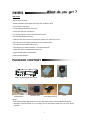
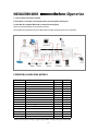
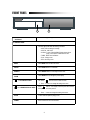
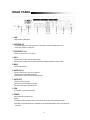
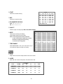
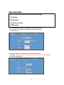
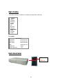
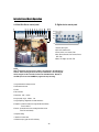
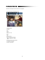
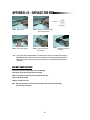
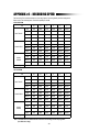
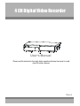
4 CH Digital Video Recorder
User’s Manual
Please read this instructions thoroughly before operation and keep the manual in a safe
place for further reference.
773W V1.0
WARNING
All the safety and operating instructions should be read before operation.
Improper operations may cause permanent damage.
• This adaptor is only for this machine.
Do not use it for other electronic products or it will damage other products.
• Please lift and place this equipment gently.
• Do not expose this equipment to direct sunlight.
• Do not use this equipment near water or in contact with water.
• Do not spill liquid of any kind on the equipment.
• Please power down the unit before unplugging.
• Do not block the ventilation holes at the top and bottom of the unit.
• Do not switch the Power On & Off within short period of time
(within 3 seconds).
• Installation should be made by qualified service personnel.
The lightning flash with arrowhead symbol, within an equilateral
triangle, is intended to alert the user to the presence of uninsulated
"dangerous voltage" within the product's enclosure that may be of
sufficient magnitude to constitute a risk of electric shock to persons.
The exclamation point within an equilateral triangle is intended to alert the
user to the presence of important operating and maintenance-(servicing)
instructions in the literature accompanying the appliance.
TABLE OF CONTENTS
What do you get ?
• FEATURES --------------------------------------------------------------------------------------- 1
• PACKAGE CONTENT ------------------------------------------------------------------------- 1
Before Operation
• INSTALLATION GUIDE ------------------------------------------------------------------------ 2
• FRONT PANEL ------------------------------------------------------------------------------------ 3
• REAR PANEL ------------------------------------------------------------------------------------- 5
Basic Operation
• GETTING STARTED ----------------------------------------------------------------------------- 6
• OPERATION --------------------------------------------------------------------------------------- 6
Detailed Menu Setup
• MAIN MENU --------------------------------------------------------------------------------------- 8
• MENU OPTIONS --------------------------------------------------------------------------------- 8
Network setting guide
• HARDWARE CONNECTION AT SERVER SITE------------------------------------------- 17
• STATIC IP SETTING ------------------------------------------------------------------------------ 18
• DYNAMIC IP SETTING ---------------------------------------------------------------------------- 22
• SOFTWARE OPERATION AT CLIENT SITE ----------------------------------------------- 34
• PLAYBACK OPERATION ----------------------------------------------------------------------- 36
• ADVANCE SETTING ----------------------------------------------------------------------------- 37
• CONNECT VIDEO WEB SERVER VIA IE BROWSER ----------------------------------- 40
Advanced Operation
• OPERATION OPTIONS -----------------------------------------------------------------------• KEY LOCK ---------------------------------------------------------------------------------------• TROUBLE SHOOTING --------------------------------------------------------------------------• SPECIFICATIONS -------------------------------------------------------------------------------APPENDIX #1 – INSTALL THE HDD ----------------------------------------------------------APPENDIX #2 – REPLACE THE HDD --------------------------------------------------------APPENDIX #3 – PIN CONFIGURATIONS ---------------------------------------------------APPENDIX #4 – RECORDING SPEED ---------------------------------------------------------
42
43
43
44
45
46
47
49
What do you get ?
FEATURES
DVR Features
• Remote control via internet
• Wavelet compression format replaces Time-Lapse VCR + Multiplexer / Quad
• 4 audio inputs / 2 audio outputs
• On Screen Display and Remote Control via PC
• Connect video web server via IE browser
• Auto sending message by e-mail or FTP when there have alarm.
• Auto recording when there have alarm.
• Picture-in-Picture (PIP) and Picture-on-Picture (POP) function in live, Linear Zoom (2x~4x)
• Motion detection & motion trigger recording function (16*12 detection point)
• Alarm input & output function( COM / NO / NC )
• Recording rate up to full size 30 fields/sec. or quad size 240 fields/sec.
• Multiple quick search by date/time/alarm/full/motion list
• Support IDE HDD capacity more than 400G.
• Security password protection
PACKAGE CONTENT
Digital Video Recorder(with HDD cartridge)
Accessories pack
Accessories pack
User’s Manual
Power Adapter and Cord
2 Keys
CD-ROM
Warning:
1. Please check the package to make sure that you receive the complete accessories which includes the components shown above.
2. This adaptor is suited for DC19V 2A use. If it is damaged, users can find replacement adaptor easily in the locality with this
specification.
1
Before Operation
INSTALLATION GUIDE
1. Connect cameras and monitor to the DVR.
2. Shown below is an example of connecting the DVR to your existing Observation System.
3. Install HDD (The compatible HDD brands are listed in the following table.)
Please refer to page.45 Appendix #1 for installation instructions.
Note: The HDD must be installed before turning on the DVR. If HDD is not installed, the DVR would function as a 4 CH multiplexer.
COMPATIBLE HARD DISK MODELS
Manufacturer
Capacity
Rotation
HITACHI
HITACHI
HITACHI
Deskstar 180 GXP (120 GB)
Deskstar 7K250, HDS722516VLAT20
Deskstar 7K250, HDS722525VLAT80
Model
120GB
160GB
250GB
7200 rpm
7200 rpm
7200 rpm
HITACHI
Deskstar 7K400, HDS724040KLAT80
400GB
7200 rpm
IBM
IBM
Maxtor
Deskstar 120GXP (80GB)
Deskstar 120GXP (120GB)
DiamondMax 536DX(60GB) 4W060H4
80GB
120GB
60GB
7200 rpm
7200 rpm
5400 rpm
Maxtor
Maxtor
Maxtor
Maxtor
Seagate
Seagate
DiamondMax Plus 9
DiamondMax Plus 9, Model#6Y120L
DiamondMax Plus 9, Model#6Y160L0
80GB
120GB
160GB
250GB
80GB
120GB
7200 rpm
7200 rpm
7200 rpm
7200 rpm
7200 rpm
7200 rpm
Seagate
Barracuda 7200.7 Plus, ST3160023A
Western Digital Caviar WD1200BB-00CAA1
160GB
120GB
7200 rpm
7200 rpm
Western Digital Caviar WD2000BB-00DWA0
200GB
7200 rpm
MaxLine Plus Ⅱ, Model#7Y250P0
Barracuda ATA IV, ST380021A
Barracuda ATA V, ST3120023A
NOTE: For non-stop long-time recording, we suggest having two HDD for recording to ensure good reliability of HDD.
2
FRONT PANEL
1
1. REMOVABLE HDD CARTRIDGE
& KEYHOLE
2
Please refer to page.44 Appendix #2.
2. CONTROL PANEL
LED LIGHT
The LED Light is ON under the following conditions.
•HDD : HDD is reading or recording.
•HDD Full : HDD is full
•ALARM : To turn off the ALARM LED light, please refer to
page.12 and set the ALARM mode as OFF.
•TIMER : When Timer is Enabled
•PLAY : Playing mode
•REC : Recording mode
MENU
Press MENU button to enter main menu.
ENTER
Press ENTER button for confirmation.
SEARCH
Press SEARCH button for searching recorded video.
ZOOM
Press ZOOM button to enlarge the picture display.
/ + PICTURE IN PICTURE
PIP: Press “
” button for Picture in Picture screen.
+ : Press “+ ” button can change the setting in the menu.
/ - 4 CHANNELS DISPLAY MODE
Press “
” button for 4 CH display modes and press twice to enter
POP (Picture On Picture) function.
- : Press “ - ” button can change the setting in the menu.
SLOW
To slow down the speed of playing mode.
POWER
Press Power to turn ON / OFF the DVR.
3
FF / ►
•FF : Play video fast forward. (Press FF button again to adjust speed
as 1, 2, 4, 8, 16, 32 times)
• ► : Under setup mode, it works as Right button.
REW / ◄
•REW : Play video fast backward. (Press REW button again to adjust
speed as 1, 2, 4, 8, 16, 32 times)
• ◄ : Under setup mode, it works as Left button.
STOP / ▼
•STOP : Under DVR Recording / Playing mode, it can stop the action.
• ▼ : Under setup mode, it works as Down button.
PAUSE / ▲
•Pause : Under DVR playing mode, it can make the action pause.
• ▲ : Under setup mode, it works as Up button.
PLAY
Press “PLAY” button to playback recorded video.
REC
Press “REC” to start recording.
CAMERA SELECT (1-4)
Press the Camera Select (1-4) to select the camera.
4
REAR PANEL
1. LAN
Connect DVR by LAN cable.
2. EXTERNAL I/O
•Controlled remotely by an external device or control system such as Video Web Server or PC.
•Alarm input, external I / O expansion.
3. VIDEO INPUT (1-4)
Connect to video source, such as camera.
4. CALL
Connect to CALL monitor. Show the Switch Display.
When the alarm is triggered, the call monitor will show the triggered channel for a period of time.
5. MAIN
Connect to Main monitor.
6. AUDIO IN (1-4)
Connect to audio sources, such as a microphone.
•IPS should be set to 30 (for NTSC) or 25 (for PAL)
* 4 audio inputs, but can only record one input at the same time.
7. AUDIO OUT
Connect to monitor or speaker.
•IPS should be set to 30 (for NTSC) or 25 (for PAL)
* with 2 mono audio outputs from the same source.
8. FAN
For ventilation, do not block the opening.
9. POWER
Please use the provided power cord.
Warning:
1. This adaptor is only for this machine. Do not use it for other electronic product or it will damage other products.
2. This adaptor is suited for DC19V 2A use If it is damaged, user can find replacement adaptor easily in the locality with this
specification.
5
Basic Operation
GETTING STARTED
Before using the DVR, please have a HDD installed ready, or it will function as 4 CH multiplexer (refer to Appendix #1 and
Appendix #2 for installation or removal of a HDD).
1. Connect the AC power cord and plug into an electrical outlet. The Red LED indicator light will be ON and the DVR is
in standby mode.
2. Press the Power button. The POWER LED will turn from red to orange, and other red LED indicators will turn ON. It
takes approximately 5 to 15 seconds to boot the system with the message : “ HDD Detecting ”. Once connected, the
POWER LED will change to green color, and the Alarm LED will be ON.
3. Before operating the DVR, sets the system time first. (refer to page.9).
NOTE : 1.If the HDD is not installed correctly or not installed, the “HDD not found” message will appear for 3 seconds
and then return to 4 CH Multiplexer display mode.
2.To switch the system, you need to turn off the power and pull out the AC power cord before reconnecting the
power. And after pressing “POWER” + “FF” to NTSC system or “POWER” + “REW” to PAL system and
reconnect the AC power cord, the system of the DVR will be switched.
OPERATION
RECORDING
The DVR offers 4 recording modes, variety of recording modes. Refer to p.11 for advanced setting of recording speed and
resolution. Under the recording status, if power is off accidentally, the recorded video will still be stored in the HDD. And
the DVR will return to original recording setting after the power restores again.
On the screen, you will find the date, time, HDD recording type, the available space of HDD (in GB) left and the symbol
“
” represents the recording mode.
2002 – JAN –01 01:02:03
NOTE : 1. Under O/W recording mode, previously recorded files will be
●OW
automatically overwritten without further warning notices, when the
HDD is full.
(OW : HDD Overwrite)
2. If the HDD capacity is only 5 GB left, it will display “5 GB” on the up-right
screen and shows orange color, and it will buzz for seconds; so as in 4GB, 3GB, 2GB and 1GB. If the
O/W Recording mode (NOTE 1) is on, it won’t have the warning buzzer.
There are 4 recording modes: Alarm, Motion, Timer and Manual Recording.
1. ALARM RECORDING
DVR is triggered by an alarm input.
symbol will be shown on the triggered channel. (refer to page12)
2. MOTION TRIGGER RECORDING
Recording is triggered by motion detection.
symbol will be shown on the triggered channel. (refer to page13)
3. TIMER RECORDING
Recording is scheduled by a Timer. It will indicate by the symbol
. (refer to page9)
4. MANUAL RECORDING
Recording is initiated manually by pressing the REC button. Symbol
6
will be shown.
PLAY BACK
Press “PLAY ” button, the DVR will show the last recording.
1. FAST FORWARD (F.F.) & FAST REWIND (F.R.)
You can increase the speed of Fast Forward and Rewind on the DVR.
In the Play mode, press “ ► ” once to get 2X speed forward and press twice to get 4X speed,… and the maximum
speed can reach 32X.
Press “◄ ” once to get 1X speed rewind and press twice to get 2X speed, … and the maximum speed can reach
32X.
2. SLOW FORWARD (S.F.) & SLOW REWIND (S.R.)
You can also slow down the speed of Forward and Rewind on the DVR.
In the Play mode, press the SLOW button and you will enter Slow mode.
Press ” SLOW ” once to get 1/2X speed forward and press “ ► ” to get 1/4X speed,… and the slowest speed can
reach 1/32X.
Press “◄ ” once to get 1/2X speed rewind and press twice to get 1/4X speed, … and the slowest speed can reach
1/32X.
3. PAUSE
You can make the playback pause and the image will be displayed on the screen.
4. STOP
Press “ STOP ” button under any circumstance, the DVR will return to live monitoring mode.
5. IMAGE JOG DIAL
It will allow you to manually view video frame-by-frame, one image at a time.
While in PLAY mode, press “ PAUSE ”, and the screen will pause.
Press “ ► ” button advances the frozen screen one image forward.
Press “ ◄ ” button moves back one image.
Note: During the LIVE or PLAY mode, press “ENTER” + “SEARCH” buttons at the same time to switch the “NORMAL” and
“SHARPNESS” display.
6. SHARPNESS
When in play mode, press “ENTER + SEARCH” to switch the sharpness( normal or sharpness )
CAMERA SELECT (1-4)
Press Camera Select (1-4) to select the camera to display in full screen.
7
MAIN MENU
Detailed Menu Setup
There are 12 options available in the Main Menu:
(MENU)
TIMER
CAMERA
RECORD
ALARM
DWELL
PIP
MOTION
DISPLAY
NETWORK
USER
SYSTEM
EVENT
TIMER ---------- Program Timer Recording
CAMERA ------- Camera Setup
RECORD ------- Recording Mode Setup
ALARM --------- Alarm Setup
DWELL --------- Dwell time Setup
PIP --------------- Picture in Picture Setup
MOTION -------- Motion Detection Setup
DISPLAY ------- Display Mode Setup
NETWORK -----Network Setup
USER ----------- User Password Setup
SYSTEM ------- System Setup
EVENT --------- Event List
Outlined below are the buttons used for Menu setting :
•“▲” and “▼” : Scroll up and down within a menu option.
• “◄” and “►” : Scroll sideways within a menu option that has been selected.
•“ + ” and “ - ” : Increase and decrease the number or change values when an option is selected and is blinking.
•ENTER : Select a submenu / an option under a submenu for browsing / modification.
•MENU : Complete modification of a menu option; exit a menu.
MENU OPTIONS
SYSTEM
1. AUDIO INPUT
To choose one of 4 channels to record. (It can only record 1 input at the same time)
2. BUZZER
Set the BUZZER “ON”, it will buzzer by event occurrence when the setting is ON.
3. EXT ALARM
To set the EXT ALARM. It will be trigged by event occurrence when the setting is ON.
4. VLOSS ALARM
To set the VLOSS ALARM. When the setting is “ON”, the alarm will start by the setting
of Buzzer, EXT alarm or Alarm Duration.
(MENU)
TIMER
CAMERA
RECORD
ALARM
DWELL
PIP
MOTION
DISPLAY
NETWORK
USER
SYSTEM
EVENT
5. MOTION ALARM
To set the MOTION ALARM. When the setting is “ON”, the alarm will start
by the setting of Buzzer, EXT alarm or Alarm Duration.
6. KEY MUTE
To set the KEY MUTE. When the setting is “YES”, there will be no sound when you press any key.
7. HDD OVERWRITE
To set the HDD OVERWRITE. When the HDD is full under O/W recording mode, previously recorded
files will be overwritten without further warning notices if the HDD OVERWRITE is ON.
8
8. MESSAGE LATCH
To select whether the DVR messages will disappear after 10
seconds or remain on screen. NO is the default setting which the
messages will disappear after 10 sec.
NOTE : Video loss, Alarm and Motion messages will be shown
like the Alarm Duration time.
9. DATE DISPLAY
To set the date Y/M/D, M/D/Y, D/M/Y or OFF on the monitor.
10. DATE
To set the date on the DVR.
11. TIME
To set the time on the DVR.
(SYSTEM)
AUDIO INPUT
1
BUZZER
ON
EXT ALARM
ON
VLOSS ALARM
ON
MOTION ALARM
ON
KEY MUTE
YES
HDD OVERWRITE
YES
MESSAGE LATCH
YES
DATE DISPLAY
D/M/Y
DATE
26-DEC-2003 [FRI]
TIME
22:55:34
CLEAR HDD
YES
SYSTEM RESET
YES
12. CLEAR HDD
Delete all the contents of the HDD. When you choose “YES” on this option, press “ENTER” and you
will be prompted with the question shown: Press “→” to clear HDD or press ”←” to cancel.
13. SYSTEM RESET
Reset all system settings back to factory default settings. Select “YES” and press “ENTER” button.
TIMER
1. DAY
Select the day, or days of the week (Mon–Fri / Sat-Sun / Daily) that you wish to schedule
the DVR to automatically record.
NOTE :
1. Date could be changed by “+” and “-” buttons.
2. If you have selected the date and Timer recording set from that specific day
to a new day, then the Timer Recording Schedule will be set as whole week.
For specific date of Timer Recording Schedule, it is not recommended to set Ending
Time over 23:59. For example: If you set Timer Schedule Day as Sunday, and
START from 11:30, but End on 00:20, then Recording Timer Schedule is set as from
every Sunday's 11:30 to next Sunday‘s 00:20. If you only want to set Recording
Timer Schedule from every Sunday 11:30 to Monday 00:20, then you should set
Recording Timer Schedule as Sunday from 11:30 to 23:59, and Monday from 00:00
to 00:20.
3. It is not suggested that users press “STOP” button or restart the system during setting
time. In doing so, the recording will stop, and users can resume recording by pressing
“ENTER” + “MENU”.
9
2. START
(TIMER)
DAY START END IPS QLT MODE
DAILY 01:00 22:00 30 BEST Q-FR
OFF 00:00 00:00 30 BEST Q-FI
OFF 00:00 00:00 30 BEST Q-FI
OFF 00:00 00:00 30 BEST Q-FR
OFF 00:00 00:00 30 BEST Q-FR
OFF 00:00 00:00 30 BEST Q-FR
OFF 00:00 00:00 30 BEST MUX
OFF 00:00 00:00 30 BEST Q-FI
TIMER ENABLE : YES
Set the time to start the recording.
3. END
Set the time to end the recording.
4. IPS (IMAGE PER SECOND)
NTSC-30、15、8、4、2、1
PAL-25、12、6、3、2、1
5. QUALITY
Select the quality of recording image: BEST, HIGH, NORM and BASIC.
6. MODE
There are three recording mode settings :
QUAD-FRAME, QUAD-FIELD, MULTIPLEX.
NOTE: To select the appropriate recording mode before
you start recording. We don’t suggest users to change
the different recording mode during recording
to ensure the best recording quality.
7. TIMER ENABLE
When TIMER ENABLE is “YES”, press “menu” button, and you
can see the timer diagram according to your setting.
CAMERA
1. TITLE
Assign a title to each camera. Initially each title is the camera’s number.
2. ALARM
Select LOW / OFF / HIGH for alarm polarity. The default value is LOW.
(CAMERA)
ALARM
REC
BR
CT
CL
HUE
CAMERA01
LOW
ON
18
15
15
18
CAMERA02
OFF
OFF
18
15
15
18
CAMERA03
HIGH
OFF
18
15
15
18
CAMERA04
HIGH
ON
18
15
15
18
TITLE
10
3. REC (RECORD)
Set up which channel you want to record.
ON : when alarm input is triggered, DVR will record alarming channel more frequently.
For example : when CH01 is triggered, the record method will become 1-2-1-3-1-4….
OFF : DVR will not record.
4. BR (BRIGHTNESS)
Adjust the brightness of each channel. The level is from 0 to 63.
5. CT (CONTRAST)
Adjust the contrast of each channel. The level is from 0 to 63.
6. CL (COLOR)
Adjust the color of each channel. The level is from 0 to 63.
7. HUE (HUE)
Adjust the hue of each channel. The level is from 0 to 63.
RECORD
1. RECORD IPS
Select the recording speed. The options are
as following :
NTSC-30、15、8、4、2、1
PAL-25、12、6、3、2、1
(RECORD)
RECORD IPS
30
QUALITY
NORMAL
RECORD MODE QUAD-FRAME
2. QUALITY
There are four quality settings : BASIC, BEST, HIGH, NORMAL.
NOTE : Please refer to page.49 APPENDIX #4 recording speed for the relationship of recording time, IPS
and recording quality.
3. RECORD MODE
There are three recording settings : QUAD-FRAME, QUAD-FIELD, MULTIPLEX.
NOTE: To select the appropriate recording mode before
you start recording. We don’t suggest to change
the different recording mode during the recording
to ensure the best recording quality.
11
ALARM
1. ALARM ENABLE
Alarm will be triggered by event occurrence when the setting is YES.
2. ALARM DURATION
Set the reaction time which was determined by how long the alarm mode
responded to a buzzer. Default setting is 10 sec. Options are 10 Sec, 15 Sec, 20
Sec, 30 Sec, 1 MIN, 2 MIN, 3 MIN, 5 MIN, 10 MIN, 15 MIN, 30 MIN, ALWAYS, AUTO.
NOTE : 1. Video loss, Alarm and Motion messages is shown like the Alarm Duration time is.
2. When the setting is AUTO, the alarm duration time is based on the setting of the external
alarm device.
3. During ALARM DURATION’S setting time, users can restart ALARM/MOTION function by
pressing both “ENTER” + “STOP” buttons.
3. REC IPS
Select the images per second of recording during an ALARM.
The options are as following:
NTSC-30、15、8、4、2、1
PAL-25、12、6、3、2、1
4. QUALITY
There are four quality settings during an alarm.
ALARM : BASIC, BEST, HIGH, NORMAL.
(ALARM)
ALARM ENABLE
YES
ALARM DURATION
15 MIN
RECORD IPS
30
QUALITY
NORMAL
RECORD MODE
QUAD-FRAME
5. RECORD MODE
There are three recording settings : QUAD-FRAME, QUAD-FIELD,
MULTIPLEX.
DWELL
1. NORM
(DWELL)
NORM ALARM
CAM1
01
01
CAM2
01
01
CAM3
01
01
CAM4
01
01
To set up the DWELL time period that each channel auto sequentially shows on call
monitor. The level is from 1 to 15 Sec or OFF.
2. ALARM
To set up the DWELL time period when alarm input is triggered.
The level is from 1 to 15 Sec or OFF.
PIP
(PIP)
FULL SCREEN
PIP SCREEN
POSITION
1. FULL SCREEN
To set up the full screen background picture display.
2. PIP SCREEN
To set up the picture with a 1/9 size screen “insert”.
3. POSITION
There are six position settings : D/L, D/M, D/R, U/L, U/M, U/R.
12
CAM 1
CAM 2
D/R
MOTION
CAM1
CAM2
CAM3
CAM4
SEN
70
70
70
70
(MOTION)
MD-NUM RE DET
03
64 ON
03
64 OFF
03
64 ON
03
64 ON
AREA
AREA
AREA
AREA
MOTION RECORD : ON
DAY
START
END
DAILY 00 : 00
00 : 00
1. SEN (SENSITIVITY)
Sets the sensitivity of the pixel-based Motion Detection feature from 1 to 99.
The highest sensitivity setting is 01, the lowest sensitivity setting is 99.
The default setting is 70.
2. MD-NUM (MOTION DETECTION NUMBER)
Sets the number of targets of the motion detection to occur in order to trigger an Alarm
(from 1-99 target areas).
Note: MD-NUM cannot be less than the number of targets set in the AREA.
3. RE (REFERENCE)
Set the Reference image to which the current screen is compared (from 1-99).
For example, the value 64 would compare the current image to the 64th previous
screen image. The higher value may increase the sensitivity.
4. DET (DETECTION)
The motion detection on each channel can be turned to be
ON or OFF individually.
5. AREA
Press the ENTER button on this option to set the Pixel-based
Motion Detection Area for each channel. Red targets represent
where the target is (Figure 1-1). Green targets represent the
Motion Detection Area(Figure 1-2), and Purple targets represent
motion currently taking place (Figure 1-3). After stopping the detection,
the color of target will be green (Figure 1- 4).
To modify the Motion Detection Area, use the following controls:
ZOOM: turn the selected target ON/OFF.
▲▼◄►: navigates between targets
- : turns all targets on the screen ON/OFF
+ : turn all targets in the selected row ON/OFF
Note: When the “DET” (DETECTION) setting is “ON”, you must set the motion detection
area or it won’t be triggered.
13
Figure 1-1
Figure 1-2
MOTION DETECTION SETUP
MOTION DETECTION SETTING — ROW SETUP
1
2
3
4
5
6
7
8
9
1
10 11 12 13 14 15 16
2
3
4
5
6
7
8
9
10 11 12 13 14 15 16
1
2
3
4
5
6
7
8
9
11
12
1
2
3
4
5
6
7
8
9
11
12
Figure 1-3
Figure 1-4
MOTION DETECTION TRIGGERED-TURN INTO PURPLE
BACK TO MOTION DETECTION SETTING
1
2
3
4
5
6
7
8
9
1
10 11 12 13 14 15 16
1
2
3
4
5
6
7
8
9
11
12
2
3
4
5
6
7
8
9
10 11 12 13 14 15 16
1
2
3
4
5
6
7
8
9
11
12
6. MOTION RECORD
When the DET setting is “ON”, you can set up the MOTION RECORD function,
1. Select “ON” to set up the motion trigger recording: It can automatically switch to Record Mode. The motion
detection will change the scanning sequence and show
on the monitor.
NOTE: The triggered recording time is based on ALARM DURATION mode setting (Please refer to page.12 for ALARM DURATION) and it will
record from the last triggered time. For example, when the alarm duration setting is 1 min, the recording time is from 9:00:00 to 9:01:00. If
the motion detection is trigged again at 9:00:40, the trigged recording time will be from 9:00:00 to 9:00:40 and 9:00:40 to 9:01:40. The total
recording time is 00:01:40.
For example : If the motion is detected on Camera #1, its recording & scanning sequence will be more frequently. The sequence
will be as 1st, 2nd, 1st, 3rd, 1st, … 4th. And channel 1 will show
on the screen. If the motion detection of 2nd
camera and 3rd camera are both activated, they will be scanning as 2nd, 3rd, 1st, 2nd, 3rd, 4th, 2nd, 3rd, 1st, 2nd, 3rd,
4th … and vice versa. And CH2 & CH3 will show
for a period of time which is just like the Alarm Duration time.
2. Select ”OFF”: The screen still shows
and if it is in recording mode, the motion detection will change the
scanning sequence.
14
7. DAY / START / END
To setup the DAY and the START/ END time for motion trigger recording timer setting.
DISPLAY
(DISPLAY)
TITLE DISPLAY
OSD COLOR
LOSS SCREEN
TIME POSITION
1. TITLE DISPLAY
To set the title shown on monitor or not.
YES
YELLOW
GREEN
NORMAL
2. OSD COLOR
Select the OSD (On Screen Display) color. The options are
YELLOW, GREEN, CYAN, BLUE, PINK, GRAY, WHITE, RED.
3. LOSS SCREEN
Retain the last picture or select the LOSS SCREEN color.
The options are GREEN, BLACK, BLUE and RETAIN.
4. TIME POSITION
To set the OSD POSITION shown on monitor.
The options are NORMAL or CENTER.
NETWORK
(NETWORK)
SERVER IP
061.062.147.111
GATEWAY
061.062.147.254
NET MASK
255.255.255.000
DNS
168.095.001.001
WEB PORT
00080
RESET DEFAULT
NO
1. SERVER IP
To set the the IP address
2. GATEWAY
To set the gateway
3. NET MASK
To set the net mask
4. DNS
To set the DNS
5. WEB PORT
To set the web port
6.RESET DEFAULT
Go back to default setting YES/NO
15
USER
1. USER
To set up the user account for controlling. It
allows 8 users setting.
(USER)
PASSWORD
Supervisor – Control all the functions.
Other Users – View all functions except the
menu setting and event list
cleaning.
SUPERVISOR
USER 1
USER 2
USER 3
USER 4
USER 5
USER 6
USER 7
2. PASSWORD
To set the security password for each account.
The maximum length of user’s password is 4
characters.
0000
0000
0000
0000
0000
0000
0000
0000
NOTE: To switch to different USER, press
“ENTER” + “MENU” buttons to “KEY
LOCK” and then enter the different user’s
password to UNLOCK.
EVENT
A single page can display 16 recorded events. Press “◄ ” or “► ” to change the
pages or press “▲” + “▼” to CLEAR the EVENT record.
DISK FULL: HDD is full
C1 VLOSS
26-DEC-2002 03:00:00
C2 ALARM
26-DEC-2002 03:00:00
K UNLOCKS 26-DEC-2002 03:00:00
M-HD ERR
26-DEC-2002 03:00:00
M-HD WARM 26-DEC-2002 03:00:00
PWR REST
26-DEC-2002 03:00:00
DMA ERROR 26-DEC-2002 03:00:00
M-HD REPL 26-DEC-2002 03:00:00
↑+↓: CLEAR
PWR REST : Power restored
M-HD REMS: HDD remove
M-HD REPL: HDD replace
M-HD ERR : HDD error
M-HD WARM: HDD warming
K UNLOCKS: Key unlock
DMA ERROR: DMA error
C1 VLOSS : The video of Channel 1 is lost
C2 ALARM : Channel 2 has been triggered by external I/O alarm
C3 MOTION: Channel 3 has been triggered by motion detection
SYSTEM ERROR: System might fail
POWER RESTORE : Power restored
16
Hardware CONNECTION
AT SERVER SITE
Network Setting Guide
17
STATIC IP SETTING
STEP1: Software installation
1.Put the attached CD into a CD-ROM and it will start to install the application program into PC.
2. Press “Next”.
3.Choose destination location and press “Next”.
18
4.Set program shortcuts setting and press “Next”.
5.Press “Next” to begin to copy files
6.After the installation, there are 6 files and 1 folder in your assigned path (file folder) as below.
19
Step2 : Static IP setting
In DVR MENU / NETWORK set SERVER IP, GATEWAY, NET MASK, DNS and WEB PORT which are provided from
your local ISP ( internet service provider ).
(MENU)
TIMER
CAMERA
RECORD
ALARM
DWELL
PIP
MOTION
DISPLAY
NETWORK
USER
SYSTEM
EVENT
For example
(NETWORK)
SERVER IP
061.066.138.074
GATEWAY
061.066.138.073
NET MASK
255.255.255.000
DNS
168.095.001.001
WEB PORT
00080
RESET DEFAULT
NO
After all network settings are finished, please connect DVR and static IP.
Static IP
20
Step3 : Connect PC and DVR via internet
Click
twice and enter your User name, Password (Note : If you never change the “Account” before, the User Name
and Password are both “admin”) and Server IP which you have set to DVR in step 2. Then click OK to connect.
21
DYNAMIC IP SETTING
Step1 : Software installation
1.Put the attached CD into a CD-ROM and it will start to install the application program into PC.
2. Press “Next”.
3.Choose destination location and press “Next”.
22
4.Set program shortcuts setting and press “Next”.
5.Press “Next” to begin copying files
6.After the installation, there are 6 files and 1 folder in your assigned path (file folder) as below.
23
Step2 : DDNS apply
1. Click on free site “http://www.dyndns.org” ( please look at the example below, you can also apply DDNS in
other DDNS web page) and “ACCOUNT”
2. Press “Create Account”
24
3. Register the information and click on “Create Account”
4.After registering your account, you will receive an e-mail, which contains instructions to
activate your account. If you do not follow these directions within 48 hours, you will need
to re-register your account.
5.Login your account.
25
6.Click on“Account” and “Add Host”
7 Users can set up their own DDNS HOST. For example, the user’s applied Host name
is “avtech.dyndns.org”. And then press “Add Host” to finish the setting.
(NOTE : Some routers don’t support some DDNS HOST)
test
Step3 : Login router
NOTE : The following settings are different from router to router. Please read the
instruction of your router thoroughly.
1.Connect PC and router (LAN end)
LAN end
POWER
26
2. Network setting for PC. (The instruction is based on Win XP O/S. If your O/S is
Win 2000 or Win 2003, the setup procedure is similar to that of Win XP O/S.)
Click
3.Click “Properties” for TCP/IP setup
27
Local Area Connection
Enabled
Realtek RTL8139 Family
twice
4.Click on “INTERNET PROTOCAL (TCP/IP)” and then select “Properties” to setup
5.Choose “Obtain an IP address automatically”
6. Enter “Command Prompt”
28
7. In the setting window, enter “ ipconfig” to write down router’s gateway(e.q. 192.168.1.1)
8. Close the window in the above step. Enter the IP address ( router’s gateway : 192.168.1.1 )
to log in to the router from internet explore. And then enter the login web page and key
in the router’s user name and password.
29
Step4 : Router setting
NOTE : In the router setting, we have four steps as follows.
1. Dial setting
2. DHCP setting
3. Virtual server setting
4. DDNS setting
1.Press “INTERNER PORT” and choose your WAN type (e.q. PPPoE), and then enter
your “User Name” and “Password” of dialing up to dynamic IP. Press save after
you finish the set up.
test
2. Press “LOCAL PORT” and set “Start IP address” and “Number of IP address”.
(For example, if the IP address of DVR is 192.168.1.10,then 10 is excluded from the setting range) Press
save after you finish setting up.
30
3. In “ADVANCED SETUP / Virtual Server”. Choose “By Port” and set “Port Number” to 80
for DVR. And set “Local Server IP Address” to 192.168.1.10. Press add after you finish the set up.
4. In “ADVANCED SETUP / Dynamic DNS”. Key in the “DNS Account”, “User Name” and
“Password” that you applied in step 3. Press save after you finish the set up.
test
31
Step 5 : IP setting
In DVR MENU / NETWORK set SERVER IP, GATEWAY, NET MASK, DNS and WEB PORT.
(MENU)
TIMER
CAMERA
RECORD
ALARM
DWELL
PIP
MOTION
DISPLAY
NETWORK
USER
SYSTEM
EVENT
For example
(NETWORK)
SERVER IP
192.168.001.010
GATEWAY
192.168.001.001
NET MASK
255.255.255.000
DNS
168.095.001.001
WEB PORT
00080
RESET DEFAULT
NO
Step6 : Connect router
ADSL modem
(WAN end)
32
Step7 : Connect to DVR via internet
1. Change PC network setting to the original setting and link PC to the internet.
2. Click
twice and enter your User name, Password and host (Note : If you never change the “Account”
before, the User Name and Password are both “admin”). Then click OK to connect.)
DDNS HOST
Note of Dynamic IP setting
*In step 2.7 : Some routers don’t support some DDNS HOST.
*In step 3.1 : Please use router’s LAN end to connect PC.
*In step 3.8 : Please use IE browser to enter router’s gateway.
*In step 4.1 : Please make sure that you have pressed save after you finish setting.
*In step 4.2 : Please make sure that you have pressed save after you finish setting.
*In step 4.3 : Please make sure that you have pressed add after you finish setting.
*In step 4.4 : Please make sure that you have pressed save after you finish setting.
*In step 6 : Please use router’s LAN end to connect to DVR. Use WAN end to connect to ADSL modem.
*In step 7 : The Server IP is the DDNS HOST which you set in step 4.4.
33
SOFTWARE OPERATION AT CLIENT SITE
Follow the steps for connection at your client site (remote site). (e.g. If you set up the server at your office with one static ADSL,
you can remotely proceed to watch the video anywhere with a networked computer.)
Step 1:Click
twice to enter Login setup (please refer to “software installation”)
Step 2:Key in “User Name” and “ Password”. (e.g. “User Name” and “Password” are “dan”
and the IP address is 61.222.50.174). Click “OK” to establish the connection.
NOTE:
1.There are two ways to get the software,
one is via the attached CD, and the other is via
Video Web Server.(Refer to APPENDIX#3)
2.You can press “Address Book”
button to add a new IP into this
table or choose any logined IP
address to access the Video Server.
3.This function is designed to store
the list of IP addresses which you
can control and manage.
Step 3:If you could see the video screen as following, you have been successfully connecting to
the server.
34
Introduction of Basic Operation
A. Video Web Server control panel
1
2 3
4 5
6
7
B. Digital device control panel
8 9 10
11 12
1
2
3
4
5
1.Camera video inputs
2.PIP, POP, QUAD screen
3.Zoom, Select, Lock, Search, Enter
4.Stop, Record, Rewind, Fast Forward, Pause,
Slow, Play
5.Menu, Left, Right, Up, Down, Exit
NOTE:
After you press the record icon, there will be a recording file in the path that you
have set. Each recording file can be saved up to 6000 frames. The recording file
will be assigned to the second file if it has more than 6000 frames. Besides, if
the HDD space is less than 200MB, the program will stop recording.
1.Image transmission rate per second
2.Data transmission rate
3.Power
4.Disconnection
5.Resolution : VGA、QVGA
6.Image quality : High、Middle、Low
7.Image adjusting : Brightness/ Contrast/ Saturation
8.Snapshot : press this button, the image will be automatically
saved in the PC.
9.Record : press this button, the recording file will be saved
in the PC automatically.
10.System setting
11.Number of online users
12.Window adjust ( right click for Full Screen)
35
PLAYBACK OPERATION
Please find a recording file in the PC and click twice on it to playback.
1
2 3
4 5
6 7 8 9 10 11 12
1. On Screen Display
2. Snapshot
3. Stop
4. Pause
5. Slow (1/2, 1/4, 1/8)
6. PLAY
7. Fast
8. OSD show / hide
9. System setting (Path of snapshot,
text color, progress color, channel
color)
10. Next (Play next file on the same folder)
11. Duration time / Play speed
12. Playback controlling bar
36
ADVANCED SETTING
Click “System Config” for advanced setting.
SYSTEM CONFIG
NOTE :
Apply-After all setting changes, press “apply” to
refresh the data.
Reboot-Press this button to restart setting.
ACCOUNT
Set up the user’s account( Max 10 accounts) ,
password and authority ( Max 6 accounts in line
at the same time) .
1.User’s level:
SUPERVISOR-control all the functions
USER LEVEL-control advanced functions
GUEST LEVEL-control basic functions only
2.Life time : During the period of time,
users are allowed to control the Video
Web Server.
Set up the ALARM function. You can use it
to operate “alarm trigger recording” function.
ALARM
1.Alarm : Enable or disable Alarm trigger function.
2.Method : Two selections—E-mail or FTP.
3.Resolution : Image storing resolution for
Email or FTP function(SUBVGA is
160 *120 QVGA is 320*240)
4.Alarm Duration : Alarm and alarm record
duration time.
5.Alarm record : Enable or disable “Alarm
trigger recording” function.
7.Alarm refresh : Clean the alarm message “
”
which is showed on the screen.
37
MAIL
When the alarm is triggered, the video server program
will capture the instant picture and e-mail the captured
image to the assigned recipients.
1.You can get all the data from the ISP
company or by mailing to the server
supplier.(POP3/SMTP server)
2.You should set the mail list which you
want to send to when the alarm is
triggered.
3.If it is not necessary for you to verify
password and user’s name, please
choose Verify as “No”.
FTP
When the alarm is triggered, the video
server program will capture the instant
picture and upload the captured image to
the assigned FTP site.
1.You can get all the data from your
MIS department.
2.The default uploading port is No.21.
3.You can set the uploading
directory by yourself.
RECORD
You can modify the storing path for recording
file and snapshot images by yourself.
38
TOOLBOX
Upgrade the firmware and get the online
users’ information.
NOTE :Do not reboot the DVR while
it is upgrading the firmware.
1.Firmware Version : The current firmware
version. You can click on “Find” button to
get the latest firmware from PC and press
“Upgrade Firmware” to upgrade it.
2.Info refresh : Refresh the online users’
information.
PERIPHERAL
You can see the default peripheral settings
in this Windows.
1.Turbo Step: Set the shift step when you
shift the zone which you see during the
zoom in function.
39
CONNECT VIDEO WEB SERVER VIA IE BROWSER
You can also connect Video Web Server via browser. This function is suitable in both WIN 2000 and WIN XP ( WIN XP is
preferable to WIN 2000)
Step 1:Open IE browser, in Tools/ Internet Options/Security/Custom Level, please select “Enable” for all options of
ActiveX.
Step 2:Enter IP address that you want to connect.
40
Step 3:Enter your Username and Password to login Video Web Server.
Step 4:After you login, you will see as below.
1.Image transmission rate per second
10.Quality switching button
2.Data transmission rate
11.Download AP button
3.User name
12.Menu, Left, Right, Up, Down, Exit
4.Video CHs
13.Lock, Zoom, Enter, Search, REC.
5.Channel switching button
14.Stop, Record, Rewind, Fast Forward, Pause, Slow, Play
6. Resolution : VGA、QVGA
15.Camera
7.Image quality : High、Middle、Low
16.4, 9, 16, Multi, PIP, POP, Power, Focus, Zoom
8.Resolution switching button
17.ESC, VCR, LIVE, FREEZE, AUTO
9.Number of online users
18.Position of view
41
Advanced Operation
OPERATION OPTIONS
ZOOM
Press ZOOM button to enlarge the display of main picture. It displays zoomed picture on main picture and a small window
inserted. The inserted window contains a movable 1/4 view size of the appointed camera. The range is from 2X to 4X.
• Press PIP button : Zoom in
• Press QUAD button: Zoom out
• Press the “Zoom” button again to leave the zoom pointer.
• Press Camera 1-4 button to select channel.
• Press ▲▼◄► button to move the zoom position.
Original
2X Zoom
4X Zoom
VIDEO LOSS
Screen will display “LOSS” in the center of display picture, if the video input is not connected properly.
SEARCH
1. LAST RECORD
Play the last recorded piece of video.
2. FULL LIST
List all recorded video on the HDD that are sorted by time.
: Motion Recording
: Manual Recording
: Alarm Recording
: Timer Recording
M : Storage in Master HDD (or S:Storage in Slave HDD)
LAST RECORD
FULL LIST
ALARM LIST
MOTION LIST
TIME SEARCH
2003-JAN-01 01:02:03 M
2003-JAN-05 05:02:03 M
2003-MAR-12 04:02:03 M
2003-APR-02 03:02:04 M
2003-MAY-01 05:02:03 M
2003-AUG-09 01:02:01 M
← : PAGE UP → : PAGE DOWN
NOTE: It will display different color on each record list
mention above.
3. ALARM LIST
List all recorded video triggered by an Alarm.
NOTE : If there is no Alarm in the record, the screen will
display “EMPTY”.
4. MOTION LIST
List all motion triggered recordings.
5. TIME SEARCH
Find video recorded on a specific date.
42
KEY LOCK
For advanced security, users can “Lock” the buttons on your DVR. Key-Lock prevents other people from using the system.
Press “ENTER” + “MENU” at the same time to enable Key Lock.
Press “ENTER” + “MENU” at the same time and key in password (Default : 0000),
then press “ENTER“ to disable Key Lock.
NOTE: To switch to different USER, press “ENTER” + “MENU” buttons to “KEY LOCK” and then enter the
different user’s password to UNLOCK.
TROUBLESHOOTING
When malfunction occurs, it may be not serious and can be corrected easily. The table below describes some typical
problems and their solutions. Please check them before calling your DVR dealer.
PROBLEM
No power
SOLUTION
l Check power cord connections.
l Confirm that there is power at the outlet.
Not working when press any
button
No recorded video
Timer Record enable does not
working
No live video
l Check if it is under Key Lock mode.
l Press "MENU" & "ENTER" to exit Key Lock mode.
l Check if the HDD is installed properly.
l Check if the Record Enable is set to YES
l Check camera video cable and connections.
l Check monitor video cable and connections.
l Confirm that the camera has power.
l Check the setting of camera lens.
NTSC & PAL System switch
To switch the system, press “POWER” + “FF” to NTSC
system and “POWER” + “REW” to PAL system.
(Refer to Page 7 "GETTING STARTED". )
43
SPECIFICATIONS
Camera Input Signal
Network Interface
Composite video signal 1 Vp-p 75Ω BNC, 4 channels
Ethernet (10/100 Base-T)
Protocals
TCP/IP, ICMP, SMTP, HTTP, FTP
Main Monitor Output
Composite video signal 1 Vp-p 75Ω BNC
Call Monitor Output
Composite video signal 1 Vp-p 75Ω BNC
4 audio inputs, (RCA) *
Audio input
2 audio outputs, (RCA) **
16 * 12 targets per camera
Audio output
Motion Detect Area
Motion Detect Sensitivity
Video Loss Detection
Refresh Rate
Recording Rate
99 Levels
Yes
240 fields/sec. <NTSC> / 200 fields/sec. <PAL>
Multiplex:Up to 30 fields/sec.< NTSC> / 25 fields/sec.<PAL>
Quad-field:Up to 120 fields/sec.<NTSC> / 100 fields/sec.<PAL>***
Quad-frame:Up to 240 fields/sec.<NTSC> / 200 fields/sec.<PAL>****
Programmable (1~15 Sec)
Yes (Movable)
Dwell Time
Picture in Picture
Key Lock
Picture Zoom
Camera Title
Video Adjustable
Alarm Input
Alarm Output
Trigger & Action
Web Interface
Time Display Format
Power Source
Yes
2*2 ~4*4 (Movable)
8 letters
Hue/ Color/ Contrast/ Brightness Adjustable
TTL input, Hi (5V), Low (GND)
COM./N.O/N.C
E-Mail images or images uploading to FTP site's specific account/
Remote Recording
Yes
YY/MM/DD, DD/MM/YY, MM/DD/YY, OFF
Power Consumption
Operation Temperature
Dimension (mm)
DC 19V
<32W
10 ~ 40℃
343(W) x 223(L) x 59(H)
• Specifications are subject to change without notice.
* 4 audio inputs, can select only 1 during operation for recording at the same time.
** with 2 mono audio outputs from the same source.
***NTSC: 4CH x 30IPS = 120 fields/sec, PAL: 4CH x 25IPS = 100 fields/sec
****NTSC: 4CH x 60IPS = 240 fields/sec,PAL: 4CH x 50IPS= 200 fields/sec
44
APPENDIX #1 – INSTALL THE HDD
Follow the steps carefully in order to ensure correct installation.
The compartment located on the front panel of the DVR is the removable Cartridge, in which
you insert the HDD. The various parts of the Cartridge are labeled for your reference.
***Note: Users need to set the HDD on the Master mode for the system detecting.***
Step 1 Connect the connector with the HDD (refer to Picture 1).
Step 2 Put HDD into the HDD cartridge. Please notice the bottom side is power side as chart shows
(refer to Picture 2).
Step 3 Screw the HDD to the cartridge. Before you screw the HDD, please be aware that you must to level
pin 1 of the HDD at pin 1 mark, because the screw hole is different from different HDD brands.
Then screw the HDD correctly (refer to Picture 3 and 4). You must precisely align the
hard disk to the pin connection to ensure correct installation.
Step 4 Reverse the HDD and put it into DVR (refer to Picture 5 and 6).
Step 5 Connect the HDD with DVR (refer to Picture 7).
Step 6 Lock the cabinet by turning the key clockwise (refer to Picture 8).
A ( locked )
B ( unlocked )
Note : If you do not lock the cabinet, the DVR system will not function properly.
Step 7 Close the cap (refer to Picture 9).
45
APPENDIX #2 – REPLACE THE HDD
A ( locked )
B ( unlocked )
Step 1 Open the cap
Step 2 Unlock the cabinet by turning
the key anti-clockwise
Step 3 Pull out the cartridge
Step 4 Loosen all screws on
the Cartridge
Step 5 Remove the HDD from
Cartridge
Note: 1. If you want to change a different HDD, you must remove the connectors from HDD ( refer to Page 51 ).
2. When HDD works for a period of time, the surface temperature will be high, please pay attention to it.
3. After turning the key to unlock position, please wait for several seconds until HDD operation stops
completely.
HDD HOT SWAP FUNCTION
Please follow the steps as following to ensure the reliability.
1)Unlock the cabinet by turning the key anti-clockwise.
2)Key in your password and press enter to disable the hard drive.
3)Pull out the HDD cartridge.
4)Replace the HDD in the tray.
Note: After turning the key to unlocked position, please wait for several seconds till HDD
operation stops completely.
46
APPENDIX #3– PIN CONFIGURATIONS
15 pin com port
•
•
DVR
•
•
9 pin com port
•
•
DVR
DQR
•
•
47
PIN 3, 4, 5, 6 ALARM INPUT
To connect wire from ALARM INPUT (PIN 3, 4, 5, 6) to GND ( PIN 9 ) connector, DVR will start recording and
buzzer will be on. When alarm has been triggered, signal becomes “Low”, and it will stop all alarm activities.
Under normal operation, signal remains “High”.
PIN 7. EXTERNAL ALARM NC
Under normal operation COM connects with NC and disconnects with NO. But when alarm is triggered, COM
disconnect with NC, and connect with NO.
PIN 8. EXTERNAL ALARM NO
Under normal operation, COM will disconnect from NO. But when Alarm is triggered, COM will connect with NO.
PIN 9. GND
GROUND
PIN 12. DISK FULL (OUTPUT)
When the HDD is full, it sends a signal to trigger next DVR recording mode, if you install another DVR. Under
normal operation, the signal remains “High”, but when the disk is full, DVR will send “Low” signal.
PIN 14. ALARM RESET (INPUT)
To connect wire from ALARM RESET ( PIN 14 ) to GND ( PIN 9 ) connector, it can disable ALARM. An external
signal to ALARM RESET ( PIN 14 ) can be used to reset both ALARM OUTPUT signal and DVR’s internal buzzer.
When alarm has been triggered, signal becomes “Low”, and it will stop all alarm activities. Under normal operation,
signal remains “High”.
PIN 15. EXTERNAL ALARM COM
Under normal operation COM connect with NC and disconnect with NO. But when alarm is triggered, COM
disconnects with NC, and connects with NO.
48
APPENDIX #4 – RECORDING SPEED
The Recording Time is different based on Recording Speed, Recording Quality and Recording Mode.
Please refer to the following table. The HDD capability is 250GB.
NTSC SYSTEM
IPS
MULTIPLEX
QUAD-FIELD
QUADFRAME
30
15
8
4
2
1
Best
50hr
100hr
187hr
375hr
750hr
1500hr
High
62hr
125hr
235hr
468hr
937hr
1875hr
Normal
100hr
200hr
375hr
750hr
1500hr
2998hr
Basic
167hr
333hr
625hr
1250hr
2498hr
4996hr
Best
48hr
95hr
178hr
356hr
712hr
1425hr
High
59hr
118hr
223hr
445hr
890hr
1781hr
Normal
95hr
190hr
356hr
712hr
1425hr
2848hr
Basic
158hr
316hr
594hr
1187hr
2373hr
4746hr
Best
24hr
48hr
89hr
178hr
356hr
713hr
High
30hr
59hr
112hr
223hr
445hr
890hr
Normal
48hr
95hr
178hr
356hr
713hr
1424hr
Basic
79hr
158hr
297hr
594hr
1187hr
2373hr
HDD Type
250 GB
PAL SYSTEM
IPS
MULTIPLEX
QUAD-FIELD
QUADFRAME
HDD Type
25
12
6
3
2
1
Best
50hr
104hr
210hr
423hr
633hr
1266hr
High
62hr
131hr
265hr
527hr
792hr
1583hr
Normal
102hr
210hr
422hr
844hr
1266hr
2542hr
Basic
168hr
350hr
704hr
1406hr
2110hr
4218hr
Best
48hr
98hr
200hr
400hr
600hr
1202hr
High
58hr
124hr
251hr
500hr
752hr
1503hr
Normal
98hr
200hr
400hr
800hr
1202hr
2414hr
Basic
160hr
332hr
668hr
1335hr
2004hr
4005hr
Best
24hr
50hr
100hr
200hr
300hr
600hr
High
30hr
62hr
125hr
250hr
376hr
751hr
Normal
49hr
100hr
200hr
400hr
601hr
1207hr
Basic
80hr
166hr
334hr
667hr
1002hr
2003hr
250 GB
Note: The data above is obtained from actual test of recording normal TV programs.
(For Reference Only)
49