1
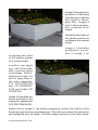
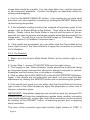
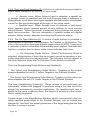
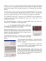
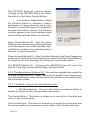
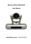
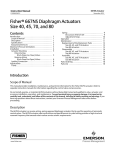
Andromeda LensDoc Filter
USER’S MANUAL
LENSDOC™
FILTER
Copyright 2006
Andromeda Software Inc.
Page ii
Licensing and Copyright Agreement
Copyright © 2006 by Andromeda Software Inc. All rights reserved. Except as
permitted under copyright law, no part of the program or this user manual may be
reproduced or distributed in any form or by any means without the prior written
permission of Andromeda Software Inc. The program, and this manual, are licensed
only for individual use on a single computer.
Limitations on Warranty and Liability
Neither Andromeda Software Inc, nor its distributors and dealers, make any warranties or representations, either expressed or implied, as to the software and
documentation, including without limitation, the condition of software and implied
warranties of its merchantability or fitness for a particular purpose.
Andromeda Software Inc. shall not be liable for any lost profits or for any direct,
indirect, incidental, consequential or other damages suffered by licensee or others
resulting from the use of the program or arising out of any breach or warranty.
Trademarks:
Adobe Photoshop and InDesign compatible plug-ins include Series 1 Photography
Filters™, Series 2 Three-D™, Series 2 Three-D Luxe™, Series 3 Screens™, Series
4 Techtures™, Shadow™, Velociraptor™, VariFocus™, Measurement™, Cutline™,
LensDoc™, Perspective™, EtchTone™, ScatterLight Lenses™, RedEyePro™ and
also the PhotoTiler Pro™ and CTBar™ for Adobe InDesign. Andromeda Series
and Suite Filters are trademarks of Andromeda Software Inc. Adobe Photoshop
is a trademark of Adobe Systems Inc. All other products are trademarks of their
respective companies.
Andromeda LensDoc Filter developed by: Dave Dyer, Dr. Steve Kundell & Donn
Gladstone
UI Design: Donn Gladstone & Dave Dyer
Technical Completion: Dr. Steve Kundell, Dave Dyer, Steve Myers & Lou Ann
Barbeau
Quality Assurance: Peter Mostowa, David Dobson, Third Eye Bangalore & Lou
Ann Barbeau
Documentation: Guy McCool, Dr. Steve Kundell & Peter Mostowa
Marketing: Brian Wynn
Sales Support: Jane Narramore & Brian Wynn
© 2006
Andromeda Software Inc.
699 Hampshire Rd, Suite 109
Thousand Oaks, CA 91361
USA.
Andromeda LensDoc Filter
Table of Contents
1.0 INTRODUCTION . . . . . . . . . . . . . . . . . . . . . . . . . . . . . . . . . . 2
2.0 HELP & QUICKSTART TUTORIAL . . . . . . . . . . . . . . . . . . . 5
2.1 Help . . . . . . . . . . . . . . . . . . . . . . . . . . . . . . . . . . . . . .5
2.2 Quick Start Tutorial. . . . . . . . . . . . . . . . . . . . . . . . . 5
2.2.1 Fix Lens Distortion . . . . . . . . . . . . . . . . . . 5
2.2.2 Fix Rectangles . . . . . . . . . . . . . . . . . . . . . 7
2.2.3 Fix Parallels . . . . . . . . . . . . . . . . . . . . . . . .7
2.2.4 Fix Rotation. . . . . . . . . . . . . . . . . . . . . . 8
3.0 THE USER INTERFACE
NOVICE MODE ANNOTATED . . . . . . . . . . . . . . . . . . . . 9
3.1 The NOVICE User Interface at a Glance . . . . . . . 9
3.2 The NOVICE User Interface Work Areas . . . . . . . 9
3.2.1 The Preview Window. . . . . . . . . . . . . . . . .9
3.2.2 The Lens Type Selection . . . . . . . . . . . . . 10
3.2.3 The Fix Type Selection . . . . . . . . . . . . . . .10
3.2.4 The Magnification Window . . . . . . . . . . . . 12
3.2.5 The Mode, Cancel
and Check Buttons . . . . . . . . . . . . . . . . . . . . . . .12
4.0 THE USER INTERFACE
EXPERT MODE ANNOTATED . . . . . . . . . . . . . . . . . . . . 13
4.1 The EXPERT User Interface at a Glance . . . . . . . .13
4.2 The EXPERT User Interface Work Areas . . . . . . . 13
4.2.1 The Line Straightening Guide
Numeric Values . . . . . . . . . . . . . . . . . . . . . . . . . .13
4.2.2 The Less/More Slider . . . . . . . . . . . . . . . . 14
4.2.3 The Center/Edge Slider . . . . . . . . . . . . . . .14
4.2.4 The Scale Slider . . . . . . . . . . . . . . . . . . . . 14
4.2.5 Graph Mode User Interface . . . . . . . . . . . .14
4.2.6 Auto Scale Button . . . . . . . . . . . . . . . . . . . 15
4.2.7 Import Lens Description Button . . . . . . . . .15
4.2.8 Export Lens Description Button . . . . . . . . .15
5.0 LENSDOC SESSIONS . . . . . . . . . . . . . . . . . . . . . . . . . 15
5.1 Lens Distortion Correction Novice Mode:
Generic Lens Correction . . . . . . . . . . . . . . . . . . . . . . . .15
5.2 Lens Distortion Correction Expert Mode:
Generic Lens Correction . . . . . . . . . . . . . . . . . . . . . . . 21
5.2.1 Generic Sliders . . . . . . . . . . . . . . . . . . . . .21
Page iv
5.3
5.4
5.5
5.6
5.2.2 Scaling Control . . . . . . . . . . . . . . . . . . . . .22
5.2.3 Saving of Settings . . . . . . . . . . . . . . . . . . .22
Lens Distortion Correction
Expert Mode: Specific Lens Correction . . . . . . . . . . 23
Rectangles Correction . . . . . . . . . . . . . . . . . . . . . 23
Parallels Correction . . . . . . . . . . . . . . . . . . . . . . . . 24
Rotation Correction . . . . . . . . . . . . . . . . . . . . . . . 25
6.0 GLOSSARY . . . . . . . . . . . . . . . . . . . . . . . . . . . . . . . . . . . . . 26
6.1 General . . . . . . . . . . . . . . . . . . . . . . . . . . . . . . . . . . 26
6.2 LensDoc Terms . . . . . . . . . . . . . . . . . . . . . . . . . . . 27
7.0 APPENDICES . . . . . . . . . . . . . . . . . . . . . . . . . . . . . . . . . . . .30
7.1 Creating Custom Zoom Lens Groups . . . . . . . . . 31
Andromeda LensDoc Filter
INTRODUCTION 1.0
LensDoc is a Photoshop compatible Plug-in that corrects lens and perspective distortion through the use of a Photoshop filter with a unique, user
friendly interface. It has modes suitable for both novice and proficient users.
By performing all corrections simultaneously, image quality is preserved.
LensDoc provides the user with the ability to correct lens distortions and
make rotational adjustments
including:
Lens Barreling: This lens
distortion causes straight
lines to bow outward like
this: ( ).
Lens Pincushioning: This
lens distortion causes
straight lines to curve inward like this: ) (.
Viewpoint Adjustment: Parallel lines appear to create a parallelogram shape
rather than being perfectly
square.
Perspective Distortion: Parallel lines appear to converge or diverge instead of
remaining truly parallel.
Axis Rotation: Important
image elements appear to
deviate from the vertical or
horizontal axis.
To see the difference, refer
to images 1-5. Image 1
shows the original uncorrected image with barreling
distortion.
Page Image 2 illustrates the
correction of Barreling
lens distortion utilizing
the LensDoc Photoshop filter. Images 3
and 4 show perspective correction of an
image:
Notice that the sides of
the garden planter do
not appear at a vertical
angle.
Image 4 illustrates
perspective correction of image 3 by
re-aligning the sides
of the garden planter
to a vertical angle.
LensDoc can apply
any or all of the available correction types
on an image. If all corrections are used, it is
best to apply them in
the order suggested,
F I X D I S TO RT I O N
first, FIX PERSPECTIVE and finally FIX
ROTATION.
Image 5 illustrates the
before and after of the
viewpoint adjustment
(FIX RECTANGLES).
Notice that in image 5, the before image(top) shows the outline of the
handicap sign forming a parralelogram. This will occur when the element is
photographed from an angle. The after image (bottom) on the other hand,
Andromeda LensDoc Filter
appears square and photographed from the front. This is useful for when an
object is not accessable directly from the
front.
The LensDoc Filter
will apply the corrections in order that you
specifiy. This allows
you to “toggle” between correction types
to “fine tune” the image.
Corrections in LensDoc are typically accomplished using
straightening guides
which are sets of three
“targets” that are represented in the Preview Window and Magnification Window as small,
moveable yellow and green boxes.
For correcting lens barreling and pincushioning, LensDoc has 2 modes:
Novice and Expert. Novice Mode provides the capability for correction by
carefully aligning one, or preferably 2 sets of points, along lines that are
curved and should be straight.
Expert Mode additionally provides for correction using sliders to adjust the
amount of correction. The Expert Mode also provides users with the tools
to save specific adjustments that apply to their lenses and control image
cropping.
Both Novice and Expert Modes allow the selection of either Generic or
Specific lens corrections: Generic correction provides the user with a group
of settings that work well for many lenses.. Specific correction is used for
specific lenses in the LensDoc encyclopedia, user saved settings, and
special effects.
NOTE: Because LensDoc applies a correction based on a full image, it
is essential that images not be cropped before applying the filter. (As an
alternative, a cropped image can be carefully placed in its original position
on a larger canvas).
Page 2.0 HELP & QUICK START TUTORIAL
2.1 Help
Installation Help: For help with installation and other issues, visit http://andromeda.com/main/tech_support.php.
Helper Window: A Helper Window is located at the bottom of the LensDoc
User Interface. As you pass the cursor over any User Interface item (buttons, windows, controls etc.), appropriate, descriptive text automatically
appears in the Helper Window to facilitate a quick understanding of the
User Interface components.
Sessions: Chapter 5 of this manual contains LensDoc tutorial sessions.
These sessions exercise the important features of the Filter that are used
to correct the various types of “barreling” and “pincushioning”.
Web site: www.andromeda.com is a source of additional visuals and information related to the LensDoc Filter product. Andromeda Software’s Adobe
Photoshop plug-in demos are available for free downloading as well as the
fully functional versions for online purchase.
2.2 Quick Start Tutorial
2.2.1 Fix Lens Distortion
1. With your image open in Photoshop, open LensDoc under: Filters --> Andromeda --> Lensdoc.
2. Make sure the Novice Mode Radio Button at the bottom right is selected.
3. Under Step 1, choose FIX DISTORTION from the right column, and
GENERIC LENS from the left column.
4. Under Step 2, click on the Yellow Guide Button (with 3 yellow squares)
to place Straightening Guide Targets in the Preview Window, if they are not
already present. If no “X” is present on the Green Guide Button, turn the
button off by clicking on it to remove the Green Targets.
5. Align the three Yellow Targets along a curved line that should be straight.
Andromeda LensDoc Filter
Choose a line near the edge of the image, if possible and don’t space the
targets too close. Drag the targets to the desired location.
After you have reached the approximate point of placement, you can refine
the adjustment by pressing the Keyboard CONTROL Key and observe the
movement of the target that appears in the Magnification Window. Release
the Mouse Button before releasing the Control Key. You can also fine tune
by moving the mouse to the Magnification Window and dragging the small
target there.
6. Click the CORRECT button.
7. If the results look good, click the Check Button at the lower right corner
of the User Interface to apply the correction or continue to another correction type.
8. In most cases, a better result will be obtained if a second set of targets
is used elsewhere in the image. Click on the Green Straightening Guide
Button and place these three additional targets on a single line anywhere
from the edge to about half way in between the edge and the center of the
image.
Note that either set of guides can be on a line that is horizontal, vertical,
or at an angle. Lines going toward the center, like spokes on a bike, won’t
work. Now click the CORRECT button again.
9. If the results are still not what you want, it is usually because the targets
are not adequately aligned or a very wide angle lens with unique characteristics is being used. Do one of the following:
If you are using a wide angle lens, switch to Specific Lens in Step 1. From
the pull-down menu, select “Alternate Barreling”. Click on the CORRECT
Button again.
Start with Alternate Barreling or any zoom lens under Specific Lens. Hold
down the Control key while you click the CORRECT button. This searches
all Specific Lenses for a best fit.
If that doesn’t work, switch to Expert Mode (bottom right). Choose Generic
Lens under Step 1. With moving targets, click the CORRECT Button to
achieve an approximate correction. Now, slowly move the Less/More Slider
until the desired correction appears in the Preview Window. If necessary, the
Center/Edge can also be adjusted. When the image correction becomes
Page acceptable, click on the Check Mark or select another correction type.
For further details, refer to the complete instructions and related tutorials
in this manual.
2.2.2 Fix Rectangles
1. Make sure the Novice Mode Radio Button at the bottom right is selected.
2. Under Step 1, choose FIX RECTANGLES from the right column.
3. Four targets are present in the Preview Window. These should be positioned along the four corners of an element in your image that should be
square, but isn’t. Position the targets by clicking and dragging.
4. Click on the MAKE RECTANGLE button. If the results are not quite what
you want, you can reset this correction by clicking the REVERT button and
re-positioning the guides.
5. If the automatic scaling function has cropped off important parts of the
image, click on Expert Mode at the bottom. Then click on the Auto Scale
Button. Finally, move the Scale Slider to the left until the parts of the image
that you wish to retrieve once again appear within the perimeter of the image area. You can also adjust the horizontal scale of the image to correct
any horizontal distortion that may have occured. You will have to crop the
final image in Photoshop. Please refer to section 5.6 Rectangle Correction
for more information.
6. If the results are acceptable, you can either click the Check Mark at the
lower right corner of the User Interface to apply the correction or proceed
to Fix Rotation.
2.2.3 Fix Parallels
1. Make sure the Novice Mode Radio Button at the bottom right is selected.
2. Under Step 1, choose FIX PARALLELS from the right column.
3. Two Parallel Line Guides with 2 targets in each set are present in the
Preview Window. These should be positioned along two elements in your
Andromeda LensDoc Filter
image that should be parallel. You can align either two vertical elements
or two horizontal elements. Position the targets as described earlier by
clicking and dragging.
4. Click on the MAKE PARALLEL button. If the results are not quite what
you want, you can reset this correction by clicking the REVERT button and
re-positioning the guides.
5. If the automatic scaling function has cropped off important parts of the
image, click on Expert Mode at the bottom. Then click on the Auto Scale
Button. Finally, move the Scale Slider to the left until the parts of the image that you wish to retrieve once again appear within the perimeter of the
image area. You will have to crop the final image in Photoshop. Please
refer to section 5.4 Parallels Correction item 5.
6. If the results are acceptable, you can either click the Check Mark at the
lower right corner of the User Interface to apply the correction or proceed
to Fix Rotation.
2.2.4 Fix Rotation
1. Make sure the Novice Mode Radio Button at the bottom right is selected.
2. Under Step 1, choose FIX ROTATION from the right column.
3. The targets in the Yellow Rotation Guide should be positioned along
an important image element that should be exactly horizontal or vertical.
Examples are the horizon line or the side or a building.
4. Click on either the ALIGN VERTICAL or the ALIGN HORIZONTAL Button.
Again, if the results are not quite what you want, you can reset this axis
adjustment by clicking the REVERT button and re-positioning the guides.
5. If the results look good, you can either click the Check Mark at the lower
right corner of the User Interface to apply the alignment or revise one of
the prior correction types.
IMPORTANT: Sometimes applying one correction type (for example FIX
PARALLELS) will hide the straightening guides when another correction
type needs adjustment. In this case, any of the corrections can be reverted
by clicking on the REVERT button, re-adjusting guides and re-applying
each correction.
The color of the correction type radio buttons (right column of STEP 1)
Page serves as a reminder of which corrections have actually been applied. Red
indicates that the correction has not been made, black indicates that it has.
The REVERT Button will return you to the last corrected state (of the current
correction type) when clicked a second time.
3.0 THE USER INTERFACE NOVICE MODE ANNOTATED
3.1 The NOVICE User Interface at a Glance
The LensDoc Filter opens with the main User Interface shown below:
3.2 The NOVICE User Interface Work Areas
The primary “work areas” in the NOVICE User Interface are:
3.2.1 The Preview Window(1): This window provides previews of the Input
Image and subsequent applications of corrections by the filter.
Andromeda LensDoc Filter
3.2.2 The Lens Type Selection(2): A choice of radio buttons is provided to
select either GENERIC or SPECIFIC lens mode.
o Generic Lens: When Generic Lens is selected, a special set
of generic curves is searched and the best fit among them is selected. In
Expert Mode, a pull-down list of types appears with the number of individual
curves for that group displayed at the right of the group name.
o Specific Lens: When Specific Lens is selected, a “pull-down”
menu appears which contains groups of lens settings for most camera
manufacturers. When the preset is selected, those settings are used to
apply lens correction. The four categories of specific lenses are digitial
camera, 35mm lenses, alternate barreling and Funhouse effects.
3.2.3 The Fix Type Selection(3): A choice of radio buttons is provided to
select either Fix Distortion, Fix Rectangles, Fix Paralles, or Fix Rotation. The
color of the correction type radio buttons (right column of STEP 1) serves as
a reminder of which corrections have actually been applied. Red indicates
that the correction has not been made; black indicates that it has.
o Fix Distortion Radio Button: When Fix Distortion Mode is
selected, straightening of lines that have been curved by barreling or pincushioning distorrtion can be performed. The following controls appear in
the User Interface when the Fix Distortion Radio Button is selected:
The Line Straightening Guide Buttons and Guides(4):
* The Yellow Line Straightening Guide Button: Toggling on this button
enables/disables the set of 3 Yellow Targets in the Preview Window.
* The Green Line Straightening Guide Button: Toggling on this button enables/disables the set of 3 Green Targets in the Preview Window.
The Line Straightening Guides(5): These groups of colored boxes are
individually “clicked and dragged” to positions along a line that should be
straight for subsequent correction application. By applying both sets of
guides to the same or different lines, the degree of accuracy of the correction is usually improved.
A guide target in the Magnification Window, which corresponds to the currently selected guide target in the Preview Window, can be clicked and
dragged to “fine tune” the actual placement of the target along the line that
the user is trying to correct.
Page 10
NOTE: If one or more guide targets appears absent during an attempted
correction, this is usually the result of it being hidden outside the visible
area of the image in the Preview Window by a correction that has been
applied.
This situation is easily resolved by using the REVERT Button to undo one
or more corrections which subsequently provides access to the desired
guides for further adjustment. The corrections can then be re-applied.
The CORRECT Button(6): Clicking on the CORRECT button applies the
correction which has been designed by either one or both sets of line
straightening guides.
The REVERT Button(7): Clicking on the REVERT button will “undo” the
effects of the CORRECT button application.
o Fix Rectangles Radio Button: When Fix
Rectangles is selected, controls appear that provide
for viewpoint adjustment in an image.
Make Rectangle Button(1): After the green and yellow
Parallel Line Guide Targets are positioned around an
element, the Make Rectangle Button is depressed to
initiate viewpoint adjustment.
The REVERT Button(2): Clicking on the REVERT
button will “undo” the effects of the Make Rectangle
button.
The Horizontal Scale Slider(3): Horizontal scale
(aspect ratio) can be adjusted when the Auto
Scale is disabled.
o Fix Parallels Radio Button: When Fix
Parallels is selected, controls appear that provide
for correction of non-parallel lines.
Make Parallel Button(8): After the green and
yellow Parallel Line Guide Targets are positioned
at opposite ends of each converging or diverging
line, the Make Parallel Button is depressed to
initiate parallel correction.
Andromeda LensDoc Filter
The REVERT Button(9, previous page):
Clicking on the REVERT button will “undo”
the effects of the Make Parallel Button.
o Fix Rotation Radio Button: When
Fix Rotation Mode is selected, rotation
adjustment of image elements can be performed to convert the angle of the element to
become horizontal or vertical. The following
controls appear in the User Interface when
the Fix Rotation Radio Button is selected:
Align Vertical Button(10): After the yellow
Rotation Line Guides are positioned at each
end of the object to be rotated, the Align Vertical Button is clicked on to rotate the angle of
the item to a vertical position.
Align Horizontal Button(11): After the yellow Rotation Line Guide Targets are
positioned at each end of the object to be rotated, the Align Vertical Button
is clicked on to rotate the angle of the item to a horizontal position.
The REVERT Button(12): Clicking on the REVERT button will “undo” the
effects of the Align Horizontal and Align Vertical buttons.
3.2.4 The Magnification Window(13): This window magnifies the area in the
Preview Window where a “target” and/or the “magnifier” were last placed.
Use the magnification slider located below this window to accurately place
the correction guides.
3.2.5 The Mode, Cancel and Check Buttons(14):
o The Mode Buttons: Choice of either Novice or Expert Modes is
made by clicking on the corresponding radio button.
The Cancel Button: This button is clicked on to cancel out of the filter and
return to the host program.
The Check Button: This button is clicked on to render the corrections that
have been applied to the image and are visible in the Preview Window.
Page 12
4.0 THE USER INTERFACE EXPERT MODE ANNOTATED
4.1 The EXPERT User Interface at a Glance
When the EXPERT button is clicked, additions to the NOVICE User Interface
are added as shown below:
4.2 The EXPERT User Interface Work Areas
The following “work areas” are added to the NOVICE User Interface when
EXPERT mode is initiated for FIX DISTORTION.
4.2.1 The Line Straightening Guide Numeric Values(1): The numeric
values below both the Yellow and Green Line Straightening Guide Buttons
indicate the straightness of the line between the points for the respective
set of guides. Zero is perfectly straight. This exact numeric value of the
correction can be seen for all of the correction modes in LensDoc.
Andromeda LensDoc Filter
4.2.2 The Less/More Slider(2): This slider controls the amount of correction
over a wide span of adjustment within the current curve family.
4.2.3 The Center/Edge Slider(3): This slider controls the shape of the
generic correction curve, concentrating the correction towards the center of
the frame or toward the edge of the frame. Usually this is a subtle effect.
4.2.4 The Scale Slider(4): This slider appears in the User Interface when
the Auto Scale button is clicked off. This slider controls the point of zero
correction from center (at left) to edge (at right) of the frame (however, this
only happens when distortion is the only correction being applied). If parallels or rotation is being applied, then the Scale Slider causes the image to
be re-scaled. Pixels from this distance to the center are not moved and
remaining pixels are adjusted relative to this position.
4.2.5 Graph Mode User Interface(5): When the “graph” icon is clicked on,
the EXPERT mode user interface is partially modified to the graph interface
shown below:
4.2.5.1 Four Curve Graphs(1): The four Alternate Graphs are
dynamically updated to illustrate permutations of what the Primary Graph
will look like as the slider(s) are moved towards extreme settings. These
curves represent 4 correction curves which are merged to produce the actual
correction. The vertical axis represents displacement from correct position
towards center or edge. The horizontal axis represents the position in the
Page 14
image from center to edge.
4.2.5.2 Corrected Image Preview Window(2): This graph reflects
changes to both the Less/More slider and the Center/Edge slider.
4.2.6 Auto Scale Button(6): When the Auto Scale mode is selected, the
image is re-scaled slightly to avoid black pixels appearing at the edges.
Some pixels are lost beyond the edges of the image. When the Auto Scale
mode is clicked off, a slider appears that provides for controling re-scaling
of the image to choose the tradeoff between black pixels and pixels lost
beyond the edges of the image perimeter. When FIX RECTANGLES is also
selected, a slider for Horizontal Scale will be present. The aspect ratio can
be adjusted using ths slider. Exact numeric changes are shown in the white
text box located directly above the MAKE SQUARE button.
4.2.7 Import Lens Description Button(7): This feature provides the capability to dynamically import additional lens descriptions from a file or folder.
Clicking on this icon will open a Load Preset File window that provides the
capability for the user to “browse” through folders on the system to locate
a specific preset to load into the Lens Preset Pull-down Menu List.
4.2.8 Export Lens Description Button(8): This feature provides the capability to dynamically export lens descriptions based on current parameter
settings. Clicking on this icon will open a Save a New Preset window that
provides the capability for the user to “browse” through folders on the system
to locate a specific folder to store the lens preset to be saved.
5.0 LensDoc SESSIONS
5.1 Lens Distortion Correction Novice Mode:
Generic Lens Correction
1. In Photoshop, open the image : Barreling grid.jpg.
This is an image with moderate barreling type distortion.
This image can be found in the set of tutorial images
that were installed on your desktop.
2. Open the LensDoc filter under Filters --> Andromeda --> Lensdoc.
3. LensDoc should be in Novice Mode. The mode is chosen by selecting
the Novice “radio style” Button at the bottom of the filter:
Andromeda LensDoc Filter
4. Under Step 1, select FIX DISTORTION from the right column, and GENERIC LENS from the left column.
5. Under Step 2, click on the Green Straightening Guides Button (the button with 3 green guides) to place green “targets” in the Preview Window if
they are not already there. If yellow targets are present on the screen, click
on the Yellow Straightening Guides Button to remove this group (an X will
appear over the button to indicate that this group has become disabled). It
doesn’t really matter which set of markers are used first.
6. Place all three green targets far apart along the same outermost black
line, choosing either a horizontal or vertical line. Do this by clicking and
dragging each of the targets to the desired location and placing them on
the black line.
Fine tune this setting by pressing the Control Key and observing the Magnification Window on the right. Release the Mouse Button (before releasing
the Ctrl key) when you are precisely over the center of the line.
Now, move the Mouse Button to the Magnification Window. If you click and
move the small target in this window, you will see that you can also fine
tune within the Magnification Window.
Page 16
7. Now click on the CORRECT button.
The lines should look straight. To see the difference the correction made,
you can revert to your original setting by clicking the REVERT button. If
you are satisfied with the settings, click on the CORRECT or REVERT
button again.
Although the correction can be applied by clicking on the Check Mark at
the lower right hand corner of the filter, wait to render the correction. If
you look carefully at the image, you will see that the inside lines don’t look
as straight as the outer line. This can be improved in two ways. One is
described below; the other follows in the Expert Mode section.
8. In many cases, the correction is more accurate if a second set of targets
is added towards the center of the image. These target points should be
placed on a single line about half way between the outer edge and the
center of the image.
Now, activate these target points by clicking on the Yellow Line Straightening Guide Button (the button with 3 yellow guides) and place the targets as
suggested in the image below.
Andromeda LensDoc Filter
9. Now click the CORRECT button. You should see a better result. Note
that it makes no difference if both sets of guides are on lines that are parallel
or perpendicular to each other. The results would be the same.
10. Choosing target placement is important. The goal is to choose lines
that you want to straighten. At least one set of marker points should be
near the edge of the image.
As noted above, placing a second set of guides part way in from the edge, increases the accuracy of the result. On the other hand, lines that run through
the center of the image or point toward the center, like spokes on a bicycle,
are straight to begin with and should never be selected as target lines. Their
selection will result in incorrect and sometimes bizarre results.
As an experiment, turn off the Green Line Straightening Guides and align
the yellow targets far apart on the diagonal line in the test image. You will
see that slight movements of
the central marker followed
by clicking the CORRECT
button result in wildly different
results.
11. Now lets try the correction
using the Specific Lens setting. Return to Step 1 in the
User Interface and choose SPECIFIC LENS. Click on the Lens Pull-down
Menu to select 35mm lenses --> Canon --> Canon EF 35-80.
Again, use only the green targets centered on an outer line (turn off the
yellow targets). Click on the CORRECT Button. You will see essentially
the same results that were achieved under generic correction with two sets
of marker points.
The improved results, in this case, are due to the fact that this is the lens
that was used to make this image. You will also see a slider under the
CORRECT button that shows the focal length that was used to photograph
the image.
If your personal lens is not available within the list of specific lenses, it is
possible to generate your own specific corrections (see tutorial on Creating
Custom Lens Groups in the Appendix) to achieve similar results with one
Page 18
set of targets.
12. To see one more powerful type of lens correction, select Alternate
Barreling from the first group of choices in the Lens Pull-down Menu. Use
both sets of targets. Now, hold down the Control Key while you click on the
CORRECT Button. LensDoc will search the entire encyclopedia of specific
lenses for a best fit. In many cases,
it will correctly identify the lens that
was used in photographing the
original image.
13. Now, try moving the Focal
Length Slider to see the effect this has on the image. You will see a change
in the correction effect. In some images, sharp edges or lines are hard to
find, so the automatic correction can only provide an approximation of what
is desired. In these cases, manual adjustment of a slider can prove very
useful for fine tuning. Note that when GENERIC LENS is chosen under
Step 1, sliders are only available in EXPERT mode.
14. We could apply the correction to the image by clicking on the Check
Mark. We will first correct perspective and rotation, but first notice that
the radio button labeled “FIX DISTORTION” at the upper right in the User
Interface has turned black. This means that the correction was applied.
Since neither of the other corrections has been applied, the other two “FIX”
Buttons are red. Now click on the FIX PARALLELS Button.
15. We wish to correct the divergence distortion that causes the outer
lines to move away from each other spanning from the bottom to the top
of the image. In the Preview Window, there are two sets of targets. Place
the yellow set on one outer vertical line and the green set on the opposite
outer vertical line.
Now click on the MAKE PARALLEL Button. The image sides should now
be parallel.
16. Finally, we will correct the rotation. Click on the FIX Rotation Button.
Align the two yellow targets far apart along the bottom line. Click on the
ALIGN HORIZONTAL Button (the one with the horizontal arrow). The image should now look fully corrected.
EXAMPLES:
Please try this procedure on the two practice images provided. These have
Andromeda LensDoc Filter
suggested target placements to assist you in beginning the process. Use
the GENERIC LENS setting under NOVICE Mode with both images:
LACMA.jpg represents extreme barreling. Place one set of straightening
guides (green targets) in the center of the designated circular targets 1,2
and 3 and another set (yellow targets) in targets A, B and C.
If a corner of the image appears to be missing when you open the Filter, click
on the REVERT button before placing target points. Note that the targets
were specifically chosen so your selections would be along straight edges.
Points X,Y, and Z are provided as an example of centrally pointed targets
that are well aligned to begin with and should not be used.
Bologna instruct.jpg shows the target points that were used for correcting
the Introduction example. This image has mild pincushioning.
For lens distortion correction, place one set of Line Straightening Guides
centered on the line within targets A, B, and C.
Place the other set on X, Y, Z. For Perspective Correction, place one set
Page 20
of guides in targets A and
C. The other set should
be placed in targets 1
and 2.
For Rotation Correction,
place the guides in either
set A and C, or set 1 and
2.
5.2 Lens Distortion
Correction Expert
Mode:
Generic Lens Correc‑
tion
Expert Mode provides
more elaborate use of
sliders to control generic
lens corrections. The
automatic straightening
guide function in Novice and Expert Modes
is identical. Additional
functions are described
as follows:
5.2.1 Generic Sliders
1. After generic lens correction using one or two sets of guides has been
performed, the image can be “fine tuned”
using two generic sliders: Less/More and
Center/Edge.
Andromeda LensDoc Filter
Although these sliders interact with each
other, the Less/More Slider basically controls the amount of correction applied. The
Center/Edge Slider adjusts how much of
the correction occurs throughout the image
versus just near the edges. The Numeric
Indicator under the straightening guide
buttons show how well your targets line up,
.000000 being the best.
2. You can choose to perform the a lens distortion correction manually using
only the sliders. In this case, select the desired type of correction from the
Lens Pull-down menu. The available generic corrections are:
Generic Barreling: For correction of barreling distortion of wide angle
lenses.
Generic Extreme Barreling: Best used with wide angle adapters.
Generic Pincushioning: For correction of pincushioning of telephoto
lenses.
Alternate Barreling: For correction of the behavior of certain fixed focal
length very wide angle lenses. (To access the Alternate Barreling correction, you must choose Specific Lens under Step 1.)
In each case, the Less/More Slider affects the strength of the correction,
and the Center/Edge Slider affects how the correction is spread from the
center toward the edge of the image.
5.2.2 Scaling Control
The Auto Scale and Scaling Slider control the final image
size to eliminate unwanted edge pixels. In most cases,
the automatic setting will suffice.
In some more extreme corrections, using the manual setting and adjusting
the slider can save important information near the sides or corners of the
image.
In some of these cases, the aspect ratio
(relation of width to height) of the final image will be changed. The Scaling Slider
is activated by clicking on the Auto Scale
button, which will cause an “X” to appear
on the button. An enabled Scale Slider will also appear . You may need to
crop your final image in Photoshop if manual scaling is used.
5.2.3 Saving of Settings
Control settings can be saved by clicking on the Folder Icon
Button with the incoming arrow.
Page 22
Useful names include the lens model and focal length (eg. super
lens 20-200 @28). These saved settings will later be available
under the list of Specific Lenses the next time you open Photoshop. They can also be imported while Photoshop is open by
clicking on the Folder Icon Button with the outgoing arrow.
5.3 Lens Distortion Correction Expert Mode:
Specific Lens Correction
This mode is essentially identical to NOVICE MODE-Specific Correction with
the addition of manual Scaling Control and Saving of Settings as described
in the previous section.
5.4 Rectangle Correction
1. To adjust rectangles in either Novice or
Expert Mode, select FIX RECTANGLES under
Step 1, right column.
2. Select the image element that you wish
to make perfectly square. Using the same procedure illustrated for lens
correction, drag and align the set of yellow targets onto the corners of this
element. This is illustrated on page 25.
Andromeda LensDoc Filter
3. Click on the MAKE RECTANGLE Button under STEP 2 to apply the correction.
REVERT will return the image preview to its
pre-corrected state. In EXPERT MODE the
horizontal and overall scale can be adjusted using the sliders to achieve a
more accurate correction.
4. If you are satisfied with the settings, the correction can be applied by
clicking on the check mark at the lower right hand corner of the filter. Alternately, you can perform a rotation correction before applying the filter.
You can also return to the lens correction (FIX ROTATION) to further fine
tune the results. The color of the Correction Radio Buttons under step 1
indicates which corrections have been applied. Black means applied; red
means not applied.
5.5 Parallels Correction
1. To correct perspective distortion in either
Novice or Expert Mode, select FIX PARALLELS
under Step 1, right column.
2. Select the image elements that you wish to
make parallel. Using the same procedure as for lens correction, drag and
align a set of yellow guides onto one line and then drag and align the green
Page 24
guides onto the other selected line.
3. Click on the MAKE / / Button under STEP
2 to apply the correction. Revert will return the
preview to the pre-corrected state. In Expert
Mode, the numeric indicator above the MAKE
/ / Button indicates the deviation between the
two lines in degrees.
4. If you are satisfied with the settings, the correction can be applied by clicking on the check mark at the lower right hand corner of the filter. Alternately,
you can perform a rotation correction before applying the filter. You can also
return to the lens correction (FIX ROTATION) to further fine tune the results.
The color of the Correction Radio Buttons under step 1 indicates which corrections have been applied. Black means applied; red means not applied.
5.6 Rotation Correction
1. To adjust rotation in either Novice or Expert Mode, select FIX ROTATION
under Step 1, right column.
2. Select the image element that you wish to
make perfectly horizontal or vertical. Using the
same procedure illustrated for lens correction,
drag and align the set of yellow targets onto this
element.
Andromeda LensDoc Filter
3. Click on the ALIGN VERTICAL or ALIGN HORIZONTAL Button under
STEP 2 to apply the correction. REVERT will
return the image preview to its pre-corrected
state. In EXPERT MODE the numeric indicator above these buttons indicates the deviation
from horizontal or vertical in degrees.
4. If you are satisfied with the settings, the correction can be applied by
clicking on the Check Mark at the lower right hand corner of the User Interface. Alternately, you can return to either of the prior correction types to
further fine tune the results. You can also return to the lens correction Fix
Distortion to further fine tune the results. The color of the Correction Radio
Buttons under step 1 indicates which corrections have been applied. Black
means applied; red means not applied.
6.0 GLOSSARY
6.1 General
Aspect Ratio: The relationship of the width to the height of an image. 35mm
images have an aspect ratio of 1.5 (36x24) whereas a square image has
an aspect ratio of 1.
Barreling: A type of lens distortion that causes straight lines at opposite
sides of an image to bow away from each other. ( )
Convergence: A type of perspective distortion that causes parallel objects
to appear to come together. For example, photographing a tall building,
upward from its base, will produce this effect.
Divergence: A type of perspective distortion that causes parallel objects to
appear to separate. For example, photographing a tall building, downward
from its top, will produce this effect.
Keystone Distortion: Perspective Distortion causing parallel elements to
appear non-parallel. This is a type of Perspective Distortion. Convergence
and Divergence are Keystone Distortions.
Lens Distortion: Imperfections in an image due to lens optics.
Perspective Distortion: Distortion of an image due to the angle from which
an image is taken.
Page 26
Pincushioning: A type of lens distortion that causes straight lines at opposite
sides of an image to bow towards each other. ) (
6.2 LensDoc Terms
1. Correct Button: This button applies automated correction to the current
marker settings
2. Correction Type: Refers to which type of distortion is being corrected, the
correction type radio buttons change from red to black when that particular
correction is applied.:
2a. FIX DISTORTION: Correction of Pincushioning and Barreling Distortion
(see above).
2b. FIX RECTANGLES: Adjustment of the viewpoint from off angle to
square.
2c. FIX PARALLELS: Correction of Convergence and Divergence (see
above).
2d. FIX ROTATION: Corrects for angular rotation of important image elements that should be horizontal or vertical. For example, this can be used
to ensure that the horizon is truly horizontal in an image, or a flagpole is
truly vertical.
3. Filter Mode: A switch along the bottom of the filter which chooses between
Novice and Expert Mode:
3a. Novice Mode: Provides a user friendly interface that provides for correction of all of the types described above with a simplified interface.
3b. Expert Mode: In addition to all Novice Mode functions, this mode
provides manual sliders for overriding some automated corrections and
manual control of scaling. Additionally, the user has the capability to save
user selected settings. Expert mode also has informative numeric values
shown to allow for a more accurate correction or adjustment.
4. Graph Mode: The Graph Mode Button is only available in Expert Mode
using lens distortion correction. The User Interface can be toggled between
the standard image preview and a display of the curves that make up the
current lens correction.
Andromeda LensDoc Filter
5. Lens Correction Type: Selects between two basic groups of corrections;
each with several subtypes. This is part of Step 1 under Lens Correction:
5a. Generic Lens: This consists of a group of corrections that work well for
many lenses. The specific subtypes listed below are only seen in Expert
Mode, but are used in Novice Mode as well. In Expert Mode, the name
appears within the Lens Pull-down Menu below the Step 1 radio buttons:
5b. Barreling: corrects Barreling Distortion.
5c. Extreme Barreling: corrects extreme Barreling Distortion often produced
by wide angle adapters, for example.
5d. Pincushioning: corrects Pincushion Distortion.
6. Specific Lens: These are corrections either for specific lenses, special
effects, or additional special generic type corrections. These choices are
available in both Novice and Expert Modes in the Lens Pull-down Menu.
The primary subtypes are:
6a. 35 mm Lenses: Correction for certain 35mm camera lenses listed by
manufacturer.
6b. Alternate Barreling: A special generic lens correction for wide angle
lenses that display greater barreling toward the center of the image than
the edge.
6c. Digital Cameras: Correction for certain digital camera lenses, listed by
manufacturer.
6d. Funhouse Effects: A myriad of special effects.
6e. User Saved Settings: Settings that will appear in the primary folder.
6f. Lens Pull-down Menu: A pull-down menu that lists the current selected
lens. This is located above the Magnification Window.
7. Line Straightening, Rectangle, Parallel and Rotation Guides: Small green
and yellow squares used to control the automated corrections in LensDoc.
These guides are activated by pressing either of the Guide Buttons displayPage 28
ing colored guides.
Each Guide Button activates three targets for Lens Correction. For Lens
Correction in Expert Mode, a numeric indicator is present below each Line
Straightening Guide Button. This indicates how close the current correction
is to a straight line (all zeros being perfect).
NOTE: The Guides’ correction function corresponds to the type of correction:
7a. Distortion: The targets determine a bowed line to be straightened.
7b. Rectangle: The targets determine a parallogram to be made square.
7c. Parallel: The targets determine end points of two non-parallel lines.
7d. Rotation: The guide determines the end points of an object that is nonvertical or non-horizontal.
8. Magnification Window: This window gives a highly magnified view of the
preview image. The location of the view is indicated by a small red square
in the preview. Clicking on any point in the preview moves the view to that
point.
Clicking on a target, moves the magnifier over the image under the target.
Holding down the Control Button, while dragging a target, will display the
target in the Magnification Window while increasing the sensitivity of target
placement. The target can also be moved in the Magnification Window. The
Magnification window can also be zoomed in and out using the magnification slider located directly under the magnification window.
9. Revert Button: This button returns the image to its pre-corrected state.
A second click returns to the last corrected state. Sometimes applying one
correction type (for example FIX DISTORTION) will hide the Straightening Guides when another correction type is attempted. In this case, any
of the
corrections can be reverted, guides readjusted, and each correction re-applied. The color of the correction type radio buttons serves as a reminder
of which corrections have actually been applied. Red indicates that the
correction has not been made; black indicates that it has.
Scaling: Adjusts the size of the image between saving all of the original
image verses cropping the image a little to remove black edge or corner
Andromeda LensDoc Filter
7.0 APPENDICES
7.1 Creating Custom Zoom Lens Groups
Custom groups for a specific zoom are especially useful to provide for
visual correction of images when there are not strong lines for placement
of Automatic Markers. It also makes automatic correction more accurate,
even when only one set of targets is used.
1. To create a setting for a specific lens, you will need to start
by photographing a very straight
target. Examples of targets include architectural structures or
custom targets such as weighted
narrow ropes. For macro work,
use straight pins or nails. It is
best to have long straight lines
near the far edge of the image
and about 1/3 and 1/2 of the way
between the center and edge.
For a zoom lens, shoot at several
focal lengths and keep records of these settings in the image, if possible.
2. Open the image canon s10 @6.jpg under Expert Mode using the
generic setting. Align both sets of markers as suggested by the targets
on the image. After carefully aligning, press the CORRECT Button. The
sliders should read around 27-30 and 80-100. Save this setting by clicking on the Save Folder Icon. Name the setting Canon S10@6.
3. Repeat the same procedure with canon s10 @8.jpg, canon s10 @10.
jpg, and canon s10 @13.jpg. Name each of the settings with the correct
focal length after the @sign. Close Photoshop.
4. Grouping these saved settings together will require manual editing
of text files. Open the folder lensdoc‑filter‑Presets (under Photoshop
--> Plug-Ins --> Andromeda --> LensDoc-Filter-Presets). Open the file
Canon [email protected]. The first lines will look like this (depending on the editor, this may look slightly different):
NAME: generic barreling1
ID: canon S10 @6
FOCAL‑LENGTH: 26
Page 30
FOCUS: 75.000
SYNTHETIC: 1
The bold items are the only ones that should be modified. All presets for
a particular zoom lens must have the same ID to be grouped together by
the filter. In this case, “canon S10” is the obvious choice. Focal length
should be changed to the actual lens focal length; for this file, 6. The
number from focus should be removed. After correction these initial
items will look like this:
NAME: generic barreling1
ID: canon S10
FOCAL‑LENGTH: 6
FOCUS:
SYNTHETIC: 1
This altered file can be saved under the original name.
5. Repeat this for canon S10 @8.txt, canon S10 @10.txt, canon S10
@13.txt, entering the respective focal lengths as 8, 10, and 13.
6.Now, re-open Photoshop. Open the image canon S10 example1.JPG.
Under either Novice or Expert Mode, choose Specific Lens and select
your new custom preset group “canon S10”. You should see a slider with
numbers from 6 to 13. Align one set of targets along one of the outer
lines. When you click on the CORRECT Button, you should see a good
correction and the lens focal length selected should be near the 6.
7. You can repeat this for canon S10 example2.JPG, canon S10 example3.JPG taken at focal lengths of 8 and 13mm. Note that good corrections will result even if the exact focal length of the lens is not identified.
Interestingly, the lens in this example has little distortion so the corrections applied by LensDoc are small. Nevertheless, the principles should
apply to all lenses.
8. When creating your own correction setsf irst try the Generic Corrections since this will work in many cases. If this does not suffice, try
searching all of the Specific Lenses. Remember that you perform this
by selecting Alternate Barreling from the Lens Selection Pull-down Menu
(you can actually use any specific zoom lens). Next, search the encyclopedia by holding down the Control Key while clicking on the CORRECT
Button. Use the correction that produces the best results.
Andromeda LensDoc Filter