1
7
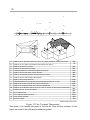
FIGURES
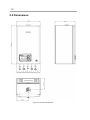
Figure 1 Boiler Dimensions16
Figure 2a-b Main Parts of the Boiler/ Front-Backside View
17
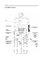
Figure 3 Water Circuit Diagram
18
Figure 4 Control Panel Appearance19
Figure 5 DHW Knob19
Figure 6 CH Knob20
Figure 7 Manometer20
Figure 8 LCD Display Screen
21
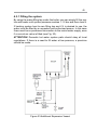
Figure 9 Hydraulic Group- Manual filling tab
24
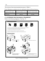
Figure 10 Transport & Packaging28
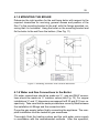
Figure 11 Mounting Schematic with essential dimensions.
29
Figure 12 Gas & Water Connections
30
Figure 13 Flue Terminal Dimensions32
Figure 14 The Parts of the Flue Kit
33
Figure 15 Wall Connections36
Figure 16 Extensions & Elbow
36
Figure 17 Standard Flue Kit Installation
37
Figure 18 Extension Flue Kit Installation
39
Figure 19 Shortening the Ducts
40
Figure 20. 90º Turning Kit Installation
41
Figure 21. Elevation Kit Installation
43
Figure 22 a) Additional Expansion Vessel, b)
Methods of Filling the System
45
Figure 23 Volumetric Flow Rate & Pressure Difference
Relation for the Circulation Pump
46
Figure 24 Main Board Diagram
51
Figure 25 Burner Pressure/ Heat Input Diagram
63
Figure 26 Gas Modulator64
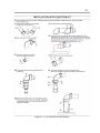
Figure 27 Burner Plates, Igniters and Flame Sensors
68