1
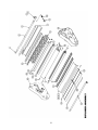
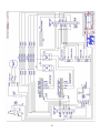
OPERATING INSTRUCTIONS
MIGHTYLAM 2700
ROLL
LAMINATOR
TABLE OF CONTENTS
Safety Messages and Electrical Safeguards ..............................3 - 4
Introduction ......................................................................................
Laminator Features ................................................................5
Specifications ..................................................................................5
Intial Set-up ....................................................................................6
Operating Instructions…………………………………………7 - 8
Operation .........................................................................................
Loading Laminating Film ......................................................8
Threading Laminating Film ................................................8 - 9
Adjusting Mandrel/Film Tension..........................................10
Heat Shoe Temperature ........................................................10
Laminating ........................................................................................
Coating Mount Board............................................................11
Mounting & Laminating........................................................12
Troubleshooting .............................................................................13
Maintenance .......................................................................................
Cleaning Heat Shoes & Rollers ............................................14
Removing Wrap-Arounds......................................................14
Warranty & Return Policy ...........................................................15
Parts List ....................................................................................16 - 17
Parts Illustrations ..............................................................................
Exploded View ......................................................................18
Side Panels .........................................................................19 - 20
Wiring Diagram......................................................................21
2
IMPORTANT SAFETY MESSAGES AND ELECTRICAL SAFEGUARDS
For your protection, do not connect the laminator to electrical power or attempt to operate it until you read
these instructions completely. Keep these instructions in a convenient location for future reference. This
instruction manual and labels affixed to the laminator are important safety messages. Read these messages
carefully.
For your safety...
Save these Operating Instructions for later use.
Keep hands, long hair, clothing, and other loose articles such as jewelry and ties, away from
laminator’s moving parts.
Do not touch the heat shoes while the laminator power is turned on. Allow shoes to cool
completely before touching.
Do not use the laminator for other than its intended purpose.
Place laminator on a sturdy cart, stand, or table. A laminator placed on an unstable surface
may fall, causing serious bodily injury. Use caution when moving laminator on a rolling cart or
stand.
Never insert objects or spill liquids in or on the laminator. They may contact dangerous
voltage points or short out components that could result in fire or electrical shock.
The laminator should only be operated from the type of power source indicated in these
Operating Instructions and on the data plate located on the rear panel of the laminator.
The three-pronged grounding plug is a safety feature and will only fit into a grounding-type
power outlet. If you are unable to insert the plug into an outlet contact a qualified electrician to
have a suitable outlet installed.
Do not leave the laminator power on overnight. Unplug the laminator at the end of the day.
Unplug the laminator before moving it or when it is not in use for an extended period of time
as a precaution against the possibility of an internal malfunction that could create a fire
hazard.
Do not operate the laminator with a damaged power supply cord or plug, or after it
malfunctions or has been damaged in any manner.
Keep the power cord away from hot or wet surfaces.
Do not overload electrical outlets beyond their capacity as this can result in fire or electrical
shock.
Adjust only those controls that are specified in these Operating Instructions.
3
If the below conditions exist do not attempt to service or repair the laminator yourself. Unplug
the laminator from the electrical outlet and contact an authorized service representative.
• When the power supply cord or plug is damaged or frayed.
• If liquid has been spilled into the laminator or it has been exposed to
water.
• If the laminator has been subjected to excessive jarring through
being dropped or bumped.
• If the laminator does not operate normally when following the
operating instructions.
KEEP THE LAMINATOR OUT OF THE REACH
OF CHILDREN.
4
INTRODUCTION
Congratulations on your purchase of the MightyLam 2700 Roll Laminator. This unit is designed to provide
years of trouble-free service.
The MightyLam 2700 will accept rolls of laminating film up to 27” wide in all film thicknesses.
Paper and card stock up to 1/16” (1.6mm) thick may be laminated without adjusting the rollers. Your
MightyLam 2700 is preset at the factory for most applications so any adjustments should be minor.
Laminator Standard Features...
Preset laminating roller pressure require no adjustment.
Feed table with adjustable guide
Dual digital heat controllers.
Teflon® coated Heat Shoes for easy cleaning.
Laminating film widths up to 27” (68.6cm).
Total material thickness up to 3/16” (4.8mm) with roller adjustment.
SPECIFICATIONS
Plastic Width
Up to 27” (68.6cm)
Plastic Thickness
1.5 mil up to 10 mil (37 to 250 micron)
Maximum Roll Length
1.5 mil - 1,000 feet (304.8 meters)
3 mil - 500 feet (152.4 meters)
5 mil - 250 feet (76.2 meters)
10 mil - 100 feet (30.5 meters)
Speed
0-10 feet per minute (3m/minute)
Net weight
97.5 lbs (44 kg)
Power Requirements
120VAC, 60Hz, 1800 watts
5
INITIAL SETUP
Unpacking...
Before unpacking the unit, inspect the shipping container for signs of damage. Notify the carrier and your
dealer immediately if any damage is noted.
Components...
Figure 1 below shows the location of the major components and controls of the
MightyLam 2700. You should become familiar with these before operating the laminator.
Figure 1
6
OPERATING INSTRUCTIONS
Heat Control
Your new MightyLam 2700 has digital heat controllers for each heat shoe. Users can easily adjust the set
temperature for each heat shoe individually to achieve the best quality lamination. Both controllers have been
calibrated to accurately display the heat shoe temperature in the laminating range.
The heater switch on the right side frame activates both controllers. When the switch is turned on both
controllers will flash a two letter code and then display the heat shoe temperature. When cold, the
temperature displayed on the controllers may be different than the actual ambient temperature to account for
correction in the higher temperature range. When the heater switch is turned on the controller will send
power to the heaters, provided the Set Temperature is higher than ambient temperature. (For safety
reasons, this machine was shipped with the Set Temperature at 250).
When power is being sent to the heaters the controllers will illuminate a small red indicator light in the lower
right hand corner of the display. The light goes out when the Set Temperature is reached. Power to the
heaters cycle on and off when the heat shoe temperature falls below the Set Temperature during lamination
or while sitting idle. The heat indicator light above the heater switch is connected to the top heat shoe only
and indicates when that heat shoe is heating.
Determining and Adjusting the Set Temperature
To determine the Set Temperature, with the heater switch activated and the current temperature displayed,
press and hold down either the up or down arrow for 3-4 seconds. The display will change and flash the Set
Temperature and “SU” alternately. After 10 seconds the display will return to the ambient/heat shoe
temperature.
To change the Set Temperature, depress and hold either arrow down for 3-4 seconds until the Set
Temperature and “SU” flash. Depress and hold the appropriate arrow to raise or lower the setting. The digits
will change slowly initially but will increase speed when held down longer for large changes. When the
desired setting has been reached, depress both arrows simultaneously to save the Set Temperature.
Each time the machine is turned on it will heat up to the last Set Temperature. It is advisable to verify the Set
Temperature when starting to warm up the machine each day.
Motor Switch: This switch controls power to the motor. After the switch is turned on, use the motor speed
potentiometer to vary the speed of film through the rollers.
Forward/Reverse Switch: This three position switch is found on the back of the machine. The switch must
be in the “down” position for forward. When the switch is held in the “up” position, and the motor switch is on,
the rollers move in the reverse direction. This is useful for clearing film from the rollers. When released from
the “up” position the switch returns to a neutral position and must be pushed down for forward.
Fan Switch: This switch turns the fans on and off. (Switch will be lighted when the fans are on).
7
OPERATION
This section describes the operation of your MightyLam 2700. This laminator is designed for all widths of
plastic up to 27”. However, if narrower widths are used the Heat Shoes must be cleaned before using a
wider roll. Refer to the MAINTENANCE section for cleaning instructions.
Loading Laminating Film onto Mandrels...
Slide the film onto the mandrel. Note that one mandrel is labeled TOP and the other BOTT (for bottom).
They are not interchangeable.
Threading Laminating Film...
These instructions apply to poly-in film rolls (shiny side out, dull side in).
1. For the top supply roll place the mandrel ends into the slots in the top of the laminator. If you are facing the front of
the laminator the film should unwind toward you from the bottom of the roll as in figure below.
2. Pull 6”-12” of film from the top roll. Pass the film under the idler bar, heat shield and over the heat shoes. Make sure
the shiny side of the film is against the shoes. See figure 5&6.
3. For the bottom supply roll, remove the feed table. Place the mandrel ends into position in the lower mandrel holder
slots. If you are facing the front of the laminator the film should unwind away from you from the bottom of the rollers
as shown in figure below.
8
4. Pull 6”-12” of film from the bottom roll. Pass it under the lower idler bar. You can “drop-down” the lower idler bar
to give you more clearance. After doing so, return the idler bar to its upper position for running the machine. Drape the
film from the bottom roll over the film from the top roll. See figures 5&6.
FIGURE 5
FIGURE 6
NOTE: The shiny side of the film must always go against the heat shoes.
The heat shoes reach a temperature of up to 350°F. Do not touch the surface of the heat shoes.
5. Turn the Motor Switch on to start the Laminating and Pull Rollers.
6. Feed a piece of thin cardboard about 10” x 25” against the film so that it is centered between the two heat shoes.
Push the cardboard and film into the laminating rollers. See figure 5. Watch cardboard pass through the back (pull)
rollers to avoid a wrap-around.
7. When the feed card has completely exited the pull rollers at the rear of the laminator turn the motor switch off.
8. Replace the feed table.
9. If you are ready to laminate, the heat switch should be in the on position and the heat indicator should have gone off.
9
Adjusting Mandrel/Film Tension…..
Each type of laminating film has different characteristics and may require laminator adjustment. The tension should be
set so that the film moves over the heat shoes without wrinkles as the film enters the laminator. Best results are
obtained if tension adjustments are made while the unit is at operating temperature. If any adjustments are required use
the following procedure:
1. Switch the heaters on. Wait for the heat shoes to reach operating temperature.
2. Press the motor switch to on.
3. Locate the knob on the right side of the top supply mandrel. See Figure 1. Turn the knob to adjust the tension
(clockwise to increase, counter clockwise to decrease) until the film passes over the top heat shoe without wrinkles and
the web between the laminating and pull rollers is tight. Note: This adjustment requires only a few degrees of turn. If
the knob is turned too far, you may stall the drive motor.
4. If necessary locate the knob on the right side of the bottom supply mandrel and adjust the tension as in step 3 above.
5. If you are not ready to laminate, turn the motor switch and heat switch off.
Setting Heat Shoe Temperature...
The laminator temperature should be adjusted according to the film thickness and the item being laminated. Contact
film manufacturer for recommended temperature settings. Keep in mind that the temperatures listed are approximate
and different brands of laminating film and heavy paper stocks may require different temperatures. Also keep in mind
that when the machine is cold the warm-up time may be longer than the heat indicator light may suggest due to the
rollers not yet having sufficient heat distribution.
Use the heater controllers on the left side of the laminator to adjust the temperature of the heat shoes. Use the
temperatures in the table below as a guide.
Material
Temperature Range
1.5 mil (.0015”)
270°F - 325°F
3 mil (.003”)
260°F - 275°F
5 mil (.005”)
250°F - 270°F
10 mil (.010”)
250°F - 270°F
Adjusting Slitter Blades
The slitter (figure 8) may be set to trim the web to the desired width as it exits the laminator. If an additional slitter
blade is installed (optional), two pages (side-by-side) may be laminated and trimmed in a single operation. (As the web
exits the unit, these pages may then be separated with the additional slitter blade).
10
Caution! If the blade release knobs are turned too far, the slitter blade may fall
out of its guide and come in contact with the rubber rollers. If this happens, the
rollers could be damaged. Never turn the blade release knobs more than one turn
to position the blades.
To Adjust the Slitter Blades:
1. Be sure the slitter blades are positioned above the laminating web. If they are lowered, loosen the release screws and
lift the blades away from the web. Tighten the screws to lock the blades in place.
2. Loosen the positioning screws (counter clockwise) and slide the slitter blades left or right to the desired width of the
edge seal. Lock the blades left or right to desired position by turning the positioning screws (clockwise).
3. Carefully, loosen each release screw and lower the blade in contact with the web. Tighten the release screw.
4. To prevent accidental damage to rollers, remove slitter blades when not in use.
Figure 8
Laminating…
1. Be sure the heaters have been turned on and are at the proper temperature. The fans should be turned on for
laminating 3mil and heavier.
Caution! Do not allow the temperature to exceed 350°F as this could cause the
laminating film to melt on the heat shoes.
2. Adjust the Paper Guide on the Feed Table so that the right edge of the item will enter the laminator at the desired
position.
3. Press the motor switch to the on position. The film will begin moving through the laminator. Please turn off fans
when the motor is not running.
4. After clear laminating film exits the pull rollers at the rear of the machine you may feed the first item to be laminated
into the laminator with the right side along the paper guide.
11
Note: You may want to run a test lamination first as any item that passes between the heat shoes will be
laminated and cannot be recovered until it exits the rear of the laminator.
5. Additional items may be fed in sequence, keeping enough distance between sheets for trimming.
6. After the last item has exited the pull rollers, turn the motor switch off.
7. Use the zippy cutter to cut across the film to remove the laminated items from the unit.
Coating Mount Board
The MightyLam 2700 is capable of applying an adhesive coating on up to 3/16” uncoated mount board.
1. Load a roll of adhesive, with the liner wound to the outside, onto the top mandrel in the same manner as with
laminating film. Thread the liner side of the adhesive over the top idler roller (so that the adhesive does not stick to the
idler roller) and then through the laminator as with laminating film.
2. If the mount board is the same width as the roll of adhesive it is not necessary to load anything onto the bottom
mandrel. If the mount board is narrower than the adhesive, load a roll of paper or film onto the bottom mandrel to keep
the adhesive from accumulating on the rollers and heat shoes. Thread as for laminating film.
3. Using the supplied allen wrench back out the four pressure adjustment screws 1 full turn for each 1/16” thickness of
the board. I.e. 3/16” 3 full turns. (Be sure to count the number of turns so the screws can be returned to original
position).
4. Turn heat switch to ON position if heat is needed for the application.
5. Set the temperature to the desired setting, depending upon the type of adhesive used.
6. Feed the uncoated mount board into the laminator behind a leader board of the same thickness. The leader board will
prevent the compression of the leading edge of your mount board.
7. You may coat subsequent boards now, one directly behind the other, so that the board in front becomes the leader
board. If at any time you have adhesive going through the machine without mount board, be sure to pull the adhesive
on the exit side of the machine to prevent a wrap-around.
Mounting & Laminating
The MightyLam 2700 is capable of simultaneously mounting and laminating a print on up to 3/16” mount board.
Preparing your print for mounting:
1. Peel back about 2” of release liner on your pre-coated mount board.
2. Align the top edge of your print with the top edge of the mount board (see figure 9).
12
Mounting your print:
1. Be sure all laminator parts (i.e. safety shield, feed table, etc.) are in their proper positions and the laminating film is
loaded correctly on top and bottom mandrels. (See page 8-9 for film loading instructions).
2. Using the supplied allen wrench back out the four pressure adjustment screws 1 full turn for each 1/16” thickness of
the board. Ie. 3/16” 3 full turns. (Be sure to count the number of turns so the screws can be returned to original
position).
FIGURE 9
3. Turn the heat switch to the ON position.
4. Set the temperature using table 1 on page 10 as a guide. You may need higher temperatures than indicated for
mounting and laminating mount board.
5. Turn the fans on.
6. Perform a test mount to ensure proper settings for successful mounting. If any adjustments are necessary make them
now and run another test. Repeat this step until you obtain desired results.
7. Feed the print and mount board slowly and evenly into the laminator behind a leader board so that the leading edge
of your mount board does not become compressed. Pull back the peeled back release liner before it enters the rollers.
8. You may mount subsequent prints now, one directly behind the other so that the board in front becomes the leader
board.
9. Once your last print has completely exited the laminator, turn the MOTOR and FAN switches OFF and use the
trimmer to remove the mounted and laminated prints.
13
TROUBLESHOOTING
PROBLEM:
Laminator is inoperative. Motor does not run, indicator lights are out.
ACTION:
Unit may be unplugged. Connect power supply. Ensure that your circuit breaker has
not tripped. Fuse may have blown. Replace 15 amp power fuse.
PROBLEM:
Laminating film and item being laminated move through laminator erratically.
ACTION:
Check thickness of item to be laminated. Maximum thickness is 1/16” (1.6mm) if
rollers have not been adjusted. Clean heat shoes of residual adhesive. Refer to
MAINTENANCE section for cleaning instructions.
PROBLEM:
Plastic is not bonding to the item or to itself at the edges.
ACTION:
Make sure heat shoes and rollers are at proper operating temperature and have had time to warm up
(Approximately 30 minutes). See table 1 for the suggested
temperature ranges.
PROBLEM:
Wrinkles appear on the laminated items running parallel with the outside edges.
ACTION:
Increase film tension on top and/or bottom supply rolls. Reduce heat shoe
temperature. Clean heat shoes of residual adhesive. See MAINTENANCE section
for cleaning instructions.
PROBLEM:
Blistering of the film appears over the item or along the edge.
ACTION:
Reduce temperature on one or both heat shoes. If the indicator light remains on after
the adjustment is made, disconnect the power supply and contact your dealer. Clean laminating
rollers. See MAINTENANCE section for cleaning instructions. There may be moisture in the
paper you are laminating. Store paper in a dry place and be sure that any ink is thoroughly dry before
laminating.
PROBLEM:
Laminated material curls after leaving pull rollers.
ACTION:
Adjust tension. If laminated item curls upwards, reduce top roller film. If item curls downward, reduce
bottom film tension. Clean heat shoes of residual adhesives as it may be causing “drag” on one side.
Refer to MAINTENANCE section for cleaning instructions.
14
MAINTENANCE
This section contains instructions for cleaning and maintaining your laminator. These procedures should be preformed
at regular intervals to help ensure the trouble-free operation of your laminator.
Cleaning the Heat Shoes and Laminating Rollers...
The heat shoes and laminating rollers should be cleaned of any residual adhesive whenever the film does not pass
smoothly over their surfaces.
NOTE: The surface of the heat shoes is Teflon coated and must only be cleaned using a soft
cloth. The heat shoes can easily be damaged by sharp or abrasive objects.
1. Allow the heat shoes to cool.
2. Remove the feed table.
3. Cut the plastic film at the top and bottom mandrels.
4. Turn the motor switch on and pull the film out of the back of the machine.
5. Turn the motor switch off.
6. Use a soft cloth moistened with denatured alcohol to remove any residue from the Teflon surface of the heat shoes
and laminating rollers.
7. Allow the heat shoes and laminating rollers to dry before re-threading the film.
Removing Wrap-Arounds...
When laminating with thinner gauges of film, there is the possibility of the film wrapping around the pull rollers. Use
the same procedure for cleaning the heat shoes and laminating rollers in order to remove a wrap-around. If the film
cannot be pulled out of the back of the machine, leave the motor and switch on and use the forward/reverse switch on
the back of the machine to reverse the rollers so the film can be pulled up and out of the machine.
15
WARRANTY AND RETURN POLICY
Warranty
Your laminator is warranted to be free of defects in material and workmanship for a period of
1 year from the original purchase date. In the event of a defect in material or workmanship,
the manufacturer or its authorized dealer, will repair or replace (at their option) the laminator.
This does not cover rollers that have been damaged due to improper usage. The manufacturer
makes no other warranty stated or implied except as stated above.
Return Policy
If your laminator is not operating properly, first review the Operating Instructions and
Troubleshooting Guide. If the malfunction cannot be corrected, contact your local dealer for
instructions. Be sure to have your machine serial number and date of purchase handy. If the
laminator must be returned to the dealer, proper packaging and freight charges are your
responsibility. Shipping damages as a result of improper packaging is not covered under the
terms of this warranty.
16
PARTS LIST AND ILLUSTRATIONS
This section contains reference drawings and a partial parts list to assist you when ordering
parts for your laminator. Some of the descriptions may have been changed for clarification.
Item
1
2
3
4
5
6
7
8
9
10
11
12
13
14
15
16
17
18
19
20
21
22
23
24
25
26
27
28
29
30
31
32
33
34
35
36
37
38
39
40
41
42
Part
No.
10333
10101
10102
10091
10100
10093
10108
10353
10090
10128
10104
10111
10983
10106
10110
10105
10816
10118
1060
10114
10115
10119
10117
10117
10120
10121
10129
10130
10325
10350
10390
10085
10815
2801
10371
10500
10814
10356
8288
10357
10393
10509
Description
BUSHING, SUPPLY MANDREL
SUPPLY MANDREL, TOP
CORE GRIPPER
C-CLIP 15/15 DIA
BRAKE, SUPPLY MANDREL
KNOB, MANDREL BRAKE
COVER, REAR
FAN HOUSING
FAN, COOLING, 120V, EZII
SUPPLY MANDREL, BOTTOM
SAFETY SHIELD
GLASS, SAFETY SHIELD
TIE BAR, REAR
TIE BAR, FRONT
HEAT SHOE
HOLDER, GLASS, HEAT SHIELD
COVER, ROLLER, REAR
MOUNT, HEAT SHOE EZII
BUSHING, IDLE ROLLER
ROD, IDLER, TOP
ROD, IDLER, BOTTOM
TUBING, IDLER ROLLER
SUPPORT, REAR, FEED TABLE
SUPPORT, FRONT, FEED TABLE
ROLLER, FRONT TOP
ROLLER, FRONT BOTTOM
ROLLER, REAR TOP
ROLLER, REAR BOTTOM
BLOCK, IDLER SPROCKET
BOLT, IDLER SPROCKET
BACKING,IDLER,BLOCK,EZII
MOTOR, EZII, 80mm
SPROCKET, IDLER,MIGHTYLAM
SPROCKET, FRONT ROLLER, 22T
SPROCKET, REAR ROLLER, 21T
SPROCKET, MOTOR, MIGHTYLAM
CHAIN, MIGHTYLAM
HEAT SINK
RELAY, SOLID STATE 25A DC
TERMINAL BLOCK, 10 STA
COVER, SIDE
HEATER, TUBULAR
17
Qty
2
1
2
4
2
2
1
1
7
1
1
1
1
1
2
1
1
8
4
1
1
2
2
1
1
1
1
1
1
1
1
1
1
1
1
1
1
1
2
1
2
6
43
44
45
46
47
48
49
50
51
52
53
54
55
56
57
58
59
10103
11539
11538
503
1319
11095
11094
10327
10337
10096
574
541
10113
10126
557
11596
11535
1395
11544
1170
1172
11540
11327
11532
10386
10389
10387
8279
2856
11611
10232
TABLE, FEED
SUPPORT, RIGHT SIDE
SUPPORT, LEFT SIDE
SPACER WASHER
LIGHT,INDICATOR,RED 120V
SWITCH, RED (HEAT)
SWITCH, GREEN (MOTOR & FANS)
SCREW, ROLLER PRESSURE
SPRING, ROLLER PRESSURE
SPRING, MANDREL BRAKE ADJUSTMENT
VARIABLE SPEED CONTROL
TERMINAL BLOCK, 6 STATION
BUSHING, ROLLER, TOP
BUSHING, ROLLER BOTTOM
KNOB, MOTOR SPEED
CONTROLLER, HEAT
FEED TABLE GUIDE ASSEMBLY
CORD, POWER 14-3
DVD, ROLL LAMINATOR
FEET, RUBBER, LARGE
FUSE HOLDER, MOTOR FUSE
FUSE HOLDER, POWER
FUSE, MAIN POWER 15AMP ABC-15
FUSE, MOTOR, 3/4 AMP AGC3/4
HEX KEY, ROLLER PRESSURE ADJUSTMENT
LABEL, RIGHT MIGHTYLAM
LABEL, LEFT MIGHTYLAM
SENSOR, K TYPE
SHAFT COLLAR, FR12, 1/2"
SLITTER BLADE ASSEMBLY
SWITCH,MOTOR FORWARD REVERSE
18
1
1
1
8
1
1
2
4
4
2
1
1
4
4
1
2
1
1
1
4
1
1
1
1
1
1
1
1
2
2
1
19
20
21
22