1
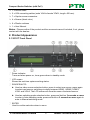
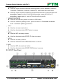
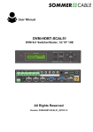
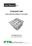
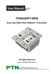
User Manual SC51T PTN Compact Scaler Switcher All Rights Reserved Version: SC51T (with PoC) 2013V1.0 www.PTN-electronics.com Compact Scaler Switcher (with PoC) NOTICE: 1. Please read this user manual carefully before using this product. 2. The item PoC is short for Power over Cable. 3. The receiver works with SC51T can only be TPHD402PR. 4. The item “far-end” means the device (e.g. display device, 3rd party RS232 device etc) connected with TPHD402PR. 5. Take notice to 4.6 Instructions of VGA Converting Cable when using. This manual is for operation instruction only, not for any maintenance usage. The functions described in this version are updated till November 2013. Any changes of functions and parameters since then will be informed separately. Please refer to the dealers for the latest details. This manual is copyright PTN Electronics Limited. All rights reserved. No part of this publication may be copied or reproduced without the prior written consent of PTN Electronics Limited. All product function is valid till 2013-11-19. Update History Version 1.0 Date 2013.11.19 Update Content First version. PTN Electronics Limited www.PTN-electronics.com Compact Scaler Switcher (with PoC) Table of Contents 1. Introduction .................................................................................................................1 1.1 Introduction to SC51T ........................................................................................ 1 1.2 Features ............................................................................................................ 1 1.3 Package Contents ............................................................................................. 1 2. Product Appearance ...................................................................................................2 2.1 SC51T Front Panel ............................................................................................ 2 2.2 SC51T Rear Panel............................................................................................. 3 3. System Connection .....................................................................................................5 3.1 Usage Precautions ............................................................................................ 5 3.2 System Diagram ................................................................................................ 5 3.3 Connection Procedure ....................................................................................... 5 3.4 Connection of Microphone ................................................................................. 6 3.5 Application ......................................................................................................... 8 4. System Operations .....................................................................................................8 4.1 Operations of Buttons ........................................................................................ 8 4.1.1 Resolution Adjusting ................................................................................8 4.1.2 Switching Operations ...............................................................................8 4.1.3 Software Updating ................................................................................. 10 4.1.4 Volume Adjusting ................................................................................... 10 4.1.5 Used in OSD Menu ................................................................................ 10 4.2 Operations of IR .............................................................................................. 11 4.2.1 IR Remote ............................................................................................. 11 4.2.2 IR Operations ........................................................................................ 12 4.3 Operations of CEC Function ............................................................................ 13 PTN Electronics Limited www.PTN-electronics.com Compact Scaler Switcher (with PoC) 4.4 Operations of RS232 Control........................................................................... 14 4.4.1 Installation/uninstallation of RS232 Control Software ............................ 14 4.4.2 Basic Settings ........................................................................................ 14 4.4.3 RS232 Communication Commands ...................................................... 15 4.4.4 Control SC51T or 3rd Party Device from Local......................................20 4.4.5 Control SC51T from Local or Remote.................................................... 20 4.5 Operations in OSD Menu................................................................................. 21 4.5.1 Option ....................................................................................................22 4.5.2 Picture ...................................................................................................23 4.5.3 Sound ....................................................................................................24 4.5.4 Setup .....................................................................................................25 4.6 Instructions of VGA Converting Cable ............................................................. 25 5. Specification ............................................................................................................. 27 6. Panel Drawing .......................................................................................................... 28 7. Troubleshooting & Maintenance ............................................................................... 29 8. Safety Operation Guide ............................................................................................ 30 9. After-sales Service ....................................................................................................31 PTN Electronics Limited www.PTN-electronics.com Compact Scaler Switcher (with PoC) 1. Introduction 1.1 Introduction to SC51T SC51T is a compact mini scaler switcher with 5 video inputs (3 HDMI, 2 VGA) and 6 audio inputs (3 HDMI audio & 2 VGA audio: switched following the video; 1 MIC audio input). As the VGA input supports VGA, YPbPr and C-video, so the scaler switcher is compliant with multiple video signals. SC51T scales & switches any video signal to HDMI output and HDBaseT output (supports PoC, connects with TPHD402PR, max transmission distance is 60 meters). And with 1 IR IN, 5 IR OUT & 1 RS232, IR & RS232 signal can be transmitted bi-directionally between SC51T and TPHD402PR. 1.2 Features Compliant with HDCP. Supports CEC, with commands to enable/disable this function. Supports video source auto-switching function. Bi-directional IR & RS232 control. Output resolutions selectable to assure preferred output, and supports various output resolutions, such as 1920x1200, 1920x1080, 1600x1200, 1360x768, 1280x800, 1280x720, 1024x768. VGA video supports C-video, YPbPr and VGA. Supports online software upgrading. 48V phantom power to support condenser microphone. MIC port supports balance/unbalance signal, suppress the external noise effectively. 3-level MIC input, supports condenser microphone, dynamic microphone and wireless microphone. Controllable via button, IR & RS232. Powerful OSD function. 1.3 Package Contents 1 x SC51T 2 x Mounting ears (separate from SC51T) 1 x Power Adapter (DC 12V) 1 x IR remote (Cell battery is not included) 1 x IR receiver (with carrier wave) 5 x IR emitters PTN Electronics Limited 1 www.PTN-electronics.com Compact Scaler Switcher (with PoC) 1 x RS232 cable 2 x VGA converting cables (male VGA to female YPbPr, length: 400 mm) 7 x Captive screw connectors 4 x Screws (black color) 6 x Plastic cushions 1 x User Manual Notes:Please confirm if the product and the accessories are all included, if not, please contact with the dealers. 2. Product Appearance 2.1 SC51T Front Panel ① Power indicator. Turns red when power on, turns green when in standby mode. ② LCD screen Shows the real-time system working status. ③ SOURCE/AUTO Used as video source selection button, press to select one source, press again to select next source, switching circularly between HDMI1, HDMI2, HDMI3, VGA1 and VGA2. The LCD screen will show the name of selected source. Used as switching mode selection button, press and hold on 3 seconds or more to enter in Auto-switching mode, press and hold on 3 seconds or more again to enter in Manual-switching mode. ④ ENTER Used to confirm selection when in menu. PTN Electronics Limited 2 www.PTN-electronics.com Compact Scaler Switcher (with PoC) ⑤ RESO/AUTO Used as output resolution manual switching button, select between 1360x768, 1280x800, 1280x720, 1024x768, 1920x1200, 1920x1080 and 1600x1200. Used as output resolution switching mode selection button, press and hold on 3 seconds or more to enter in Auto-switching mode, press and hold on 3 seconds or more again to enter in Manual-switching mode. ⑥ MENU/FWUPDATE Used as menu button, press it to enter in OSD menu. Used as software updating button, press and hold on 7 seconds or more to enter in software updating procedure. ⑦ VOL Used as volume down button. Used as direction button NEXT when in menus. ⑧ MIC+ Used as MIC volume up button. Used as direction button MOVE UP when in menus. ⑨ VOL+ Used as volume up button. Used as direction button PREVIOUS when in menus. ⑩ MIC Used as MIC volume down button. Used as direction button MOVE DOWN when in menus. 2.2 SC51T Rear Panel PTN Electronics Limited 3 www.PTN-electronics.com Compact Scaler Switcher (with PoC) ① AUDIO INPUT 3 HDMI audio & 2 VGA audio inputs. User can choose any one audio (embedded HDMI audio or external input audio) for HDMI audio input by using RS232 commands. ② AUDIO OUTPUT Audio output port, the audio comes from the input audio corresponding to the selected video source and mixed with MIC audio. ③ IR OUT 5 ports in total. Connects with IR emitter, used to control local source device or SC51T from remote, switches following the corresponding video source. ④ IR IN Connects with IR receiver (with carrier wave only), to receive IR signal send by the IR remote or remote controller of other input/output device. ⑤ FIRMWARE USB port, connects with USB flash disk or other storage which is with update file inside, to update the system firmware. ⑥ RS232 Serial control port, 3p captive screw connector, connects with a control device (such as a computer) to control SC51T or other device connected with TPHD402PR. ⑦ 12V DC Power port. Connects with the 12V DC power adapter. ⑧ MIC a) MIC port, connects with microphone. b) Dial switch, 3 levels: 48V phantom power mode (connects with condenser microphone), MIC mode (connects with dynamic microphone) and LINE mode (connects with wireless microphone or line audio). ⑨ VIDEO INPUT Video input ports, includes 3 HDMI inputs & 2 VGA inputs. VGA ports supports YPbPr, C-video and VGA format. Factory default is VGA format. ⑩ OUTPUT c) HDMI local output d) HDBaseT output, supports PoC. The audio part of the two ports are same, and is mixed with MIC audio and HDMI embedded audio (output audio), and if disable HDMI embedded audio output, then there will be no audio output through these ports. PTN Electronics Limited 4 www.PTN-electronics.com Compact Scaler Switcher (with PoC) 3. System Connection 3.1 Usage Precautions 1) System should be installed in a clean environment and has a prop temperature and humidity. 2) All of the power switches, plugs, sockets and power cords should be insulated and safety. 3) All devices should be connected before power on. 3.2 System Diagram 3.3 Connection Procedure Step1. Connect HDMI source devices (e.g. Blue-ray DVD) to HDMI input ports of SC51T with HDMI cable. Connect VGA source device (e.g. PC) to VGA input ports of SC51T with VGA cable. Step2. Connect the corresponding audio source to the corresponding AUDIO INPUT port of SC51T with audio cable one to one. The audio of HDMI can be embedded or external by sending right command. Step3. Connect HDMI display device to HDMI output port of SC51T with HDMI cable. Step4. Connect TPHD402PR to HDBaseT output port of SC51T with twisted pair. Step5. Connect speaker, headphone or PTN amplifier to AUDIO OUTPUT port of SC51T. Step6. Connect control device (e.g. PC) to RS232 port of SC51T or TPHD402PR (bi-directional RS232 control, either is available). Step7. Both SC51T and TPHD402PR have IR IN and OUT. When one model is used for PTN Electronics Limited 5 www.PTN-electronics.com Compact Scaler Switcher (with PoC) IR signal receiver, the IR signal must be sent out by the other model. For example: When “IR IN” of SC51T connects with an IR receiver, the IR transmitter must connect to IR OUT of TPHD402PR. The IR signal can be transmitted bi-directionally between SC51T and TPHD402PR. Step8. Select MIC level and connect right microphone to MIC input port. MIC audio will be transmitted to AUDIO OUTPUT port and mixed with source audio. Step9. Connect DC12V power adaptor to the power port (TPHD402PR is able to get power from SC51T). 3.4 Connection of Microphone SC51T provides with one 3-level microphone input, to accommodate different microphone input modes, including 48V phantom power mode, MIC mode & LINE mode. 48V phantom power input When switch to “48V” (It has a good frequency characteristic, high input impedance and high sensitivity in this mode), the MIC input will provide a 48V phantom power. This is only used for condenser microphone. Connection is: “+” connects to positive, “-” connects to negative and “ ” to ground. MIC input When switch to “MIC” (It has a low frequency characteristics, and wide frequency response in this mode), the microphone input is used for connecting with dynamic microphone. There are two different connections: 1) Unbalanced connection: “+” and “ ” connect to ground, and “-” connects to signal. “-” and “ ” connect to ground, and “+” connects to signal. PTN Electronics Limited 6 www.PTN-electronics.com Compact Scaler Switcher (with PoC) 2) Balanced connection: “+” connects to positive, “-” connects to negative and “ connects to ground. ” LINE input When switch to “LINE” (It has a low frequency characteristics, and wide frequency response in this mode), the microphone input is used for connecting with line audio or wireless microphone output. There are two different connections: Unbalanced connection: “+” and “ ” connect to ground, and “-” connects to signal. “-” and “ ” connect to ground, and “+” connects to signal. b) Balanced connection: “+” connects to positive, “-” connects to negative and “ connects to ground. PTN Electronics Limited 7 ” www.PTN-electronics.com Compact Scaler Switcher (with PoC) 3.5 Application SC51T has a good application in various occasions, such as computer realm, monitoring, conference room, big screen displaying, television education, command & control center and smart home etc. 4. System Operations 4.1 Operations of Buttons The buttons can be used for output resolution adjusting, switching operations, software updating, volume adjusting and operations in menus. 4.1.1 Resolution Adjusting Supports auto-adjusting and manual-adjusting. Press and hold on RESO/AUTO button for 3 seconds or more to enter in auto-adjusting/manual-adjusting mode. Notice: In auto-adjusting mode, SC51T will choose the resolution of the display device at the far-end as the preferred resolution. If need to choose the resolution of local HDMI display device: Cut off the power of SC51T and break the connection between SC51T and TPHD402PR. Turn on the power of SC51T. Gets the resolution of local HDMI output device. Connect TPHD402PR to SC51T. 4.1.2 Switching Operations Supports auto-switching and manual-switching. Press and hold on SOURCE/AUTO button for 3 seconds or more to enter in auto-switching/manual-switching mode. The display result is showed as below: IN: HDMI1 MANUAL 1280 X 720 IN: HDMI1 AUTO 1280 X 720 The display result will be showed for 2 seconds. PTN Electronics Limited 8 www.PTN-electronics.com Compact Scaler Switcher (with PoC) Auto-switching function The auto-switching mode follows the listed principles: New input principle Once detecting a new input signal, SC51T would switch to this new signal automatically. Power rebooting principle SC51T offers the function to remember the signal last displayed when rebooting. Once rebooting, SC51T will automatically enter in auto-switching mode, and then detect all inputs and memorize their connection status for future rebooting using. And if the signal last displayed is still available, then it will choose the signal to output. If not, there will be no signal on outputs. Signal removing principle Once removing the current display signal, SC51T will detect all input signals with priority from INPUT 1 to INPUT 5. It will transfer the signal firstly detected to be available to outputs. Notice: Auto-switching function works only when input with new signal, remove a signal or power rebooting. Operation Examples: Connect the INPUT 2, INPUT 4, and INPUT 5 ports to the source devices, select INPUT 4 to outputs. Press and hold on the front key SOURCE/AUTO for 3 seconds or more to enter in auto-switching mode. No signal removing or new input, SC51T just works in auto-switching mode, and take no action (Output from INPUT 4) Connect INPUT 3 with a source device, and then it will choose INPUT 3 to output. Remove the signal of INPUT 3, SC51T will detect from INPUT 1 to INPUT 5. And when it detects that input 2 is available, it will choose INPUT 2 to output. Cut off the power of SC51T, then reboot. As SC51T is in auto-switching mode, then it will choose INPUT 2 to output. PTN Electronics Limited 9 www.PTN-electronics.com Compact Scaler Switcher (with PoC) 4.1.3 Software Updating Software updating means to update the inside program of this scaler switcher. SC51T supports software updating via USB flash disk. The Operation is: 1) Copy the file “MERGE.bin” to a USB flash disk. (The “MERGE.bin” file is provided/authorized by PTN engineering department or from our website: http://www.PTN-electronics.com) 2) Plug the USB flash disk to the SC51T USB port on its front panel. 3) Press the button “MENU” for 7 seconds or more to update the software automatically. Or press this button for 6 seconds until it comes out an update OSD and then select “Option” “Software Update” to enter in update procedure. Or send command 50689% to update software. 4.1.4 Volume Adjusting Not in OSD menu, press VOL -- to decrease line volume, VOL + to increase. Not in OSD menu, press MIC – to decrease MIC volume, MIC + to increase. 4.1.5 Used in OSD Menu Press MENU button to enter in OSD menu, and use UP, DWON, LEFT, RIGHT button to select, press ENTER button to confirm selection. MENU button also can be used to exit present menu level by level until exit the OSD menu. PTN Electronics Limited 10 www.PTN-electronics.com Compact Scaler Switcher (with PoC) 4.2 Operations of IR 4.2.1 IR Remote As IR signal can be transmitted bi-directionally between SC51T and TPHD402PR, it is able to use the IR remote at the far-end to control SC51T or HDMI source devices (via CEC function buttons). ① Standby button To enter in/exit standby mode. ② Input channel selection buttons INPUT 1 is for HDMI1, INPUT 2 for HDMI2…INPUT 5 for VGA2. AUTO button: Enable/disable auto-switching mode. ③ Volume adjusting buttons MIC-/+: decrease/increase MIC volume LINE-/+: decrease/increase line volume MIC MUTE: mute/unmute MIC audio LINE MUTE: mute/unmute line audio ④ Menu operation buttons MENU: press to enter in OSD menu or used to return to previous menu. EXIT: exit OSD menu. OK: confirm button. ,,, : UP/DWON/LEFT/ RIGHT button, for value setting or page-turn, Buttons in area a are also able to work in CEC mode to enter the menu of HDMI source device. P.P, ZOOM, S.M: shortcut button, to select display mode. ⑤ Resolution selection buttons Select the resolution by pressing corresponding button. AUTO is for auto-selecting best resolution. ⑥ CEC function buttons These are for HDMI input signal which supports CEC. Includes PLAY, PAUSE, STOP, MENU, REV (reverse) and FWD (forward). PTN Electronics Limited 11 www.PTN-electronics.com Compact Scaler Switcher (with PoC) 4.2.2 IR Operations The 5 IR OUT ports are corresponding to the 5 video inputs one to one, and switch following the corresponding video source. 1) Control far-end device from local To control SC51T or far-end display device from local by using corresponding remote controller. 2) Control local device from remote To control SC51T or local source device from remote by using corresponding remote controller. PTN Electronics Limited 12 www.PTN-electronics.com Compact Scaler Switcher (with PoC) 4.3 Operations of CEC Function Supports CEC and CEC standby functions, and can be enabled/disabled through RS232 commands or OSD menu. If the HDMI source device supports CEC, and when SC51T enter in standby/startup mode, then the source device will automatically enter in standby/startup mode. And due to CEC function, user can control HDMI source device with basic operations (play, pause, fast forward, fast reverse, menu etc). So user is able to control SC51T and HDMI source device via the IR remote of SC51T. Commands for CEC function: “50686%” (enable CEC) and “50687%” (disable CEC). The working status related to CEC and STANDBY is showed as below: Situation CEC: on, Standby: on CEC: on, Standby: off CEC: on CEC: off Working Status Press STANDBY button on IR remote, SC51T enters in standby mode, so do all HDMI source devices. Press STANDBY button on IR remote, SC51T enters in standby mode, HDMI source devices keep on. Use CEC function buttons, ▲,▼, , and OK buttons on IR remote to control HDMI source devices, include play, pause, fast forward, fast reverse and operations in menu. Unable to control HDMI source devices through IR remote PTN Electronics Limited 13 www.PTN-electronics.com Compact Scaler Switcher (with PoC) CEC: Control HDMI source devices by IR remote of SC51T 4.4 Operations of RS232 Control As RS232 can be transmitted bi-directionally between SC51T and TPHD402PR, so it is able to control a third party RS232 device from local or control SC51T from remote. When to control a third party RS232 device, the baud rate of this device should be 2400, 4800, 9600, 19200, 38400, 57600 or 115200. 4.4.1 Installation/uninstallation of RS232 Control Software Installation Copy the control software file to the computer connected with SC51T. Uninstallation Delete all the control software files in corresponding file path. 4.4.2 Basic Settings First to connect SC51T with all input devices and output devices needed, then to connect it with a computer which is installed with RS232 control software. Double-click the software icon to run this software. Here we take the software CommWatch.exe as example. The icon is showed as below: The interface of the control software is showed as below: PTN Electronics Limited 14 www.PTN-electronics.com Compact Scaler Switcher (with PoC) Parameter Configuration area Monitoring area, indicates if the command sent works. Command Sending area Please set the parameters of COM number, bound rate, data bit, stop bit and the parity bit correctly, and then you are able to send command in Command Sending Area. 4.4.3 RS232 Communication Commands Communication protocol: RS232 Communication Protocol Baud rate: 9600 Data bit: 8 Stop bit: 1 Parity bit: none Command Function Feedback Example 50600% MUTE line audio LINE Mute on 50601% UnMute line audio LINE Mute off 50602% Line audio volume up LINE Volume: XX 50603% Line audio volume down LINE Volume: XX 50604% Lock the front panel buttons key lock 50605% Unlock the front panel buttons key unlock Preset the volume. The XX is ranging from 501XX% LINE Volume: XX 00 to 99 Preset the brightness. The XX is ranging 502XX% Brightness: XX from 00 to 99 PTN Electronics Limited 15 www.PTN-electronics.com Compact Scaler Switcher (with PoC) 50621% 50626% 50627% 50628% 50629% Preset the contrast. The XX is ranging from 00 to 99 Preset the saturation. The XX is ranging from 00 to 99 Preset the sharpness. The XX is ranging from 00 to 07 Auto-adjust the input parameter(VGA only) Auto-adjust the color temperature ZOOM the image, set the aspect ratio OK, for OSD selection LEFT button RIGHT button UP button DOWN button set the picture mode SM audio mode MENU button Reset to factory defaults EXIT button Change the resolution to 1360X768 HD Change the resolution to 1920X1200 WUXGA Change the resolution to 1600X1200 UXGA Change the resolution to 1024X768 XGA Change the resolution to 1280X720 720P Change the resolution to 1280X800 WXGA Change the resolution to 1920X1080 1080P 50630% Check the volume level 50631% 50632% 50633% 50634% 50635% 50636% 50637% 50638% 50639% 50640% 50646% Check the input source Check the output resolution Check the image mode Check the audio mode Check the image aspect ratio Check the brightness Check the contrast Check the saturation Check sharpness Check the color temperature Enable MIC Volume bar display 503XX% 504XX% 505XX% 50606% 50607% 50608% 50609% 50610% 50611% 50612% 50613% 50614% 50615% 50616% 50617% 50618% 50619% 50620% PTN Electronics Limited 16 Contrast: XX Saturation: XX Sharpness: XX pc auto Color Temp: XX Aspect Ratio: XX key: ok key: left key: right key: up key: down Picture Mode : XX Sound Mode: XX key: menu factory reset key: exit resolution:1360*768 resolution:1920*1200 resolution:1600*1200 resolution:1024*768 resolution:1280*720 resolution:1280*800 resolution:1920*1080 LINE Volume: XX MIC Volume: XX Source: XXXXXX Resolution: XXXXXXXX Picture Mode : XX Sound Mode: XX Aspect Ratio: XX Brightness: XX Contrast: XX Saturation: XX Sharpness: XX Color Temp: XX Volume Bar: Display www.PTN-electronics.com Compact Scaler Switcher (with PoC) 50647% Disable MIC Volume Bar display 50648% Enable HDMI embedded audio output 50649% Disable HDMI embedded audio output 50651% Check Volume Bar display status 50652% Check Digital audio output status 50655% 50656% 50698% 50701% 50702% 50703% 50704% 50705% Freeze output image Cancel the freezing of output image Software (inside program) update Switch to HDMI 1 input (INPUT 1) Switch to HDMI 2 input (INPUT 2) Switch to HDMI 3 input (INPUT 3) Switch to VGA 1 input (INPUT 4) Switch to VGA 2 input (INPUT 5) Choose HDMI embedded audio as HDMI audio input for port HDMI 1 (INPUT 1) Choose external audio as HDMI audio input for port HDMI 1 (INPUT 1) Choose HDMI embedded audio as HDMI audio input for port HDMI 2 (INPUT 2) Choose external audio as HDMI audio input for port HDMI 2 (INPUT 2) Choose HDMI embedded audio as HDMI audio input for port HDMI 3 (INPUT 3) Choose external audio as HDMI audio input for port HDMI 3 (INPUT 3) 50706% 50707% 50708% 50709% 50710% 50711% 50720% Mute LINE audio & MIC audio 50721% Unmute LINE audio & MIC audio 50722% 50723% 50724% 50725% 508XX% 50751% 50752% 50753% Mute MIC audio Unmute MIC audio MIC volume up MIC volume down Set MIC volume to XX Check if the LINE audio is mute or not Check if the MIC audio is mute or not Check the freeze status PTN Electronics Limited 17 Volume Bar: No Display Digital Sound Output: Enable Digital Sound Output: Disable Volume Bar: XXXXXXXX Digital Sound Output: XXXXXXXX Freeze: Enable Freeze: Disable switch to hdmi1 switch to hdmi2 switch to hdmi3 switch to vga1 switch to vga2 HDMI1 AUDIO LINE1 AUDIO HDMI2 AUDIO LINE2 AUDIO HDMI3 AUDIO LINE3 AUDIO LINE Mute On MIC Mute On LINE Mute Off MIC Mute Off MIC Mute On MIC Mute Off MicVolume ++ MicVolume -MIC Volume: XX LINE Mute On/Off MIC Mute On/Off Freeze: Enable/Disable www.PTN-electronics.com Compact Scaler Switcher (with PoC) 50754% 50787% 50788% Check the panel locked status Enable serial control mode 1 (control SC51T & far-end from local) Enable serial control mode 2 (control SC51T from local or far-end) Panel Locked/Unlocked Pc control far end Far end control 51T 50761% Not display mute icon of LINE audio in OSD 50762% Display mute icon of LINE audio in OSD 50763% Not display mute icon of MIC audio in OSD 50764% Display mute icon of MIC audio in OSD 50765% 50766% 50780% 50781% 50670% Not display freeze icon in OSD menu Display freeze icon in OSD menu Enable HDCP Disable HDCP Display channel display menu when switching Not display channel display menu when switching Check if display the channel display menu when switching EDID management, copy the best resolution data of one output to one input automatically Enable automatically source detecting (i.e. auto-switching) Disable automatically source detecting (i.e. manual-switching) Move the image to right 50671% Move the image to left 50672% Move up the image 50673% Move down the image 50644% 50645% 50650% 50782% 50785% 50786% 50674% 50675% Stretch left from left side (increase image width) Pull right from left side (decrease image width) PTN Electronics Limited 18 ICON LINE Mute: ENABLED ICON LINE Mute: DISABLED ICON MIC Mute: ENABLED ICON MIC Mute: DISABLED ICON Freeze: ENABLED ICON Freeze: DISABLED HDMI OUT HDCP On HDMI OUT HDCP Off OSD Source: Display OSD Source: No Display OSD Source: XXXXXX Open Source Auto Close Source Auto ADJUST OUTPUT X XX ADJUST OUTPUT X XX ADJUST OUTPUT Y XX ADJUST OUTPUT Y XX ADJUST OUTPUT WIDTH XX ADJUST OUTPUT WIDTH XX www.PTN-electronics.com Compact Scaler Switcher (with PoC) 50676% 50677% 50678% Stretch upwards from top side (increase image height) Stretch upwards from down side (decrease image height) Enable screen output adjusting (then able to adjust screen output through OSD menu) 50679% Disable screen output adjusting 50680% Select VGA source for INPUT 4 (VGA 1) 50681% Select YPbPr source for INPUT 4 (VGA 1) 50682% Select C-video source for INPUT 4 (VGA 1) 50683% Select VGA source for INPUT 5 (VGA 2) 50684% Select YPbPr source for INPUT 5 (VGA 2) 50685% Select C-video source for INPUT 5 (VGA 2) 50686% 50687% 50791% 50792% 50699% Enable CEC Disable CEC HDCP on HDCP off Check the system version ADJUST OUTPUT HEITHT XX ADJUST OUTPUT HEITHT XX Open output position adjust Close output position adjust Input4 Select VGA1 SWITCH TO VGA1 Input4 Select YPbPr1 SWITCH TO YPbPr1 Input4 Select AV1 SWITCH TO AV1 Input5 Select VGA2 SWITCH TO VGA2 Input5 Select YPbPr2 SWITCH TO YPbPr2 Input5 Select AV2 SWITCH TO AV2 Enable HDMI CEC Disable HDMI CEC HDCP ON HDCP OFF VX.X.X Note: For the command with background color, it is available only when switched to corresponding input port. For example, when switched to INPUT1 (HDMI1), and then choose HDMI embedded audio/external audio as HDMI audio of this port, it can be successfully set, and the feedback is “set in HDMI1 port”. PTN Electronics Limited 19 www.PTN-electronics.com Compact Scaler Switcher (with PoC) 4.4.4 Control SC51T or 3rd Party Device from Local Firstly, connect the RS232 port of SC51T to RS232 port of PC. Secondly, send command 50787% (serial control mode 1, factory default) via RS232 communication software. Lastly, send the right command of SC51T or other remote RS232 device connected in present system. Connect as below: Control SC51T or 3rd party device from local 4.4.5 Control SC51T from Local or Remote Control SC51T from local Firstly, connect the RS232 port of SC51T to RS232 port of PC. Secondly, send command 50788% via RS232 communication software. Lastly, send the right command to control SC51T. Connect as below: PTN Electronics Limited 20 www.PTN-electronics.com Compact Scaler Switcher (with PoC) Control SC51T from local Control SC51T from remote Firstly, connect the RS232 port of far-end RS232 device to RS232 port of PC. Secondly, send command 50788% via RS232 communication software. Lastly, send the right command to control SC51T. Connect as below: Control SC51T from remote 4.5 Operations in OSD Menu SC51T provides a powerful OSD operation menu, contains 4 parts: optional settings, image settings, audio settings and system setting etc. Press MENU button on front panel (or MENU button on IR remote/send command 50616%) to enter in OSD menu, so it is able to do some settings through the OSD menu. PTN Electronics Limited 21 www.PTN-electronics.com Compact Scaler Switcher (with PoC) 4.5.1 Option Includes Software Update (USB), Output Adjust, Input4 Select and Input5 Select. Software Update (USB): Insert the USB flash disk with updating file to USB port of SC51T, to update the software through this menu. Output Adjust: Adjust output image position (X: horizontal direction and Y: vertical direction) and ratio aspect (width and height). Input4 Select: Select video source format for VGA input, includes AV 1 (C-video signal), VGA 1 (VGA signal) and YPbPr 1 (Component video signal). Use ENTER button to select the right source format. Input5 Select: Select video source for VGA input, includes AV 2 (C-video signal), VGA 2 (VGA signal) and YPbPr 2 (Component video signal). Use ENTER button to select the right source format. For INPUT4 & INPUT5, when change for new format signal: 1. Firstly, please select a format through this menu (the signal format changed while the video source is still the same). 2. Secondly, switch off the present signal channel (e.g. switch to another channel). 3. Thirdly, switch to channel INPUT4/INPUT5 again. PTN Electronics Limited 22 www.PTN-electronics.com Compact Scaler Switcher (with PoC) 4.5.2 Picture Including Picture Mode, Color Temperature, Aspect Ratio, Noise Reduction, Screen and Color Range. Please check the picture below: Picture mode: Includes Dynamic, Standard, Mild, and User. And only in User mode, it is able to set the image contrast and brightness. Color Temperature: Includes Cool, Medium, Warm and User. And only in User mode, it is able to set values for Red, Green and Blue (RGB). Aspect Ratio: Includes Auto, 4:3, 16:9, Zoom1, Zoom2, Just Scan, Panorama, and Point To Point. VGA format only supports 4:3, 16:9 and Point to Point. Noise Reduction (not for VGA format): Includes Off, Low, Middle, High and Default. Screen: (not for HDMI source): Includes Auto Adjust, Horizontal, Vertical, Size, and Phase. Color Range (not for VGA format): Includes 0~255 and 16~235, use ENTER button to select the color range. PTN Electronics Limited 23 www.PTN-electronics.com Compact Scaler Switcher (with PoC) 4.5.3 Sound Including Sound Mode, Surround Sound and EQ. Please check the picture below: Sound mode: Includes Standard, Music, Movie, Sports and User. Only User mode supports to set treble and bass. Surround Sound: Includes Off, Surround and SRS Trusurround XT. EQ: To adjust the sound balance. PTN Electronics Limited 24 www.PTN-electronics.com Compact Scaler Switcher (with PoC) 4.5.4 Setup Including OSD Language, Blending, HDMI CEC and OSD Duration. OSD Language: Supports 14 languages, including English (default), Chinese etc. Blending: Includes Low, Middle, High and Off. Use ENTER button to select. HDMI CEC: Enable/disable CEC and auto-standby function. Default: CEC on, STANDBY on. OSD Duration: Includes 5 s, 10 s, 15 s and Off. “s” is for Second. 4.6 Instructions of VGA Converting Cable As VGA source supports YPbPr and C-video source, SC51T provides with 2 VGA converting cables to compliant with these signals. When need to select these signals as input source, please switch to channel INPUT 4 (or INPUT 5), and then set the signal type in OSD. And then switch to other input channel and connect INPUT 4 (or INPUT 5) with corresponding source device. At last, please switch to INPUT4 (or INPUT 5) again. Connect with Component Video (YPbPr) Source A. Operation Examples: 1. Via front panel buttons & OSD Press MENU button on front panel to enter in OSD, and then enter in OPTION setting menu: set “INPUT 4 Select” to YPbPr1, and “INPUT 5 Select” to YPbPr2. After setting, press SOURCE/AUTO button on front panel to switch to YPbPr1 or PTN Electronics Limited 25 www.PTN-electronics.com Compact Scaler Switcher (with PoC) YPbPr2 source. 2. Via RS232 commands Send command 50681% (or 50684%) to switch to YPbPr1 (or YPbPr2) source. 3. Via IR remote & OSD Press MENU button on IR remote to enter in OSD, and then enter in OPTION setting menu: set “INPUT 4 Select” to YPbPr1, and “INPUT 5 Select” to YPbPr2. After setting, press INPUT 4 (or INPUT 5) button to switch to YPbPr1 (or YPbPr2) source. B. Connecting the VGA converting cable like this: Connect with Composite Video (C-VIDEO) Source A. Operation Examples: 1. Via front panel buttons & OSD Press MENU button on front panel to enter in OSD, and then enter in OPTION setting menu: set “INPUT 4 Select” to AV1, and “INPUT 5 Select” to AV2. After setting, press SOURCE/AUTO button on front panel to switch to AV1 or AV2 source. 2. Via RS232 commands Send command 50682% (or 50685%) to switch to YPbPr1 (or YPbPr2) source. 3. Via IR remote & OSD Press MENU button on IR remote to enter in OSD, and then enter in OPTION setting menu: set “INPUT 4 Select” to AV1, and “INPUT 5 Select” to AV2. After setting, press INPUT 4 (or INPUT 5) button to switch to AV1 (or AV2) source. B. Connecting the VGA converting cable like this: PTN Electronics Limited 26 www.PTN-electronics.com Compact Scaler Switcher (with PoC) 5. Specification Video Input Input Input Connector Video Signal Video Output 3 HDMI 2 VGA 3 female HDMI 2 female VGA (15 pin) HDMI, YPbPr, C-video, VGA Output Output Connector Video Signal IR Input Input 1 IR IN Input 3.5mm mini jack Connector Video General Resolution Range Maximum Pixel Clock Gain HDCP Audio Input Input Input Connector Input Impedance Audio General IR Output Output Output Connector 1024x768, 1280x720, 1280x800, 1920x1080, 1600x1200, 1920x1200 Bandwidth Video Impedance Input / Output 0dB Level Compliant with DVI & HDMI 1.3 standards Audio output 3 Dual-mono stereo audio for HDMI 2 Dual-mono stereo Output audio for VGA (Support C-VIDEO, YPbPr, VGA) Output 3P captive (3.81mm) Connector Output >10kΩ Impedance 165MHz Frequency Response 20Hz~20K Hz CMRR >90dB @20Hz to 20K Hz Stereo Channel Separation 1 HDMI 1 HDBaseT 1 female HDMI 1 RJ45 1 HDMI 1 HDBaseT 5 IR OUT 3.5mm mini jack HDMI:4.95Gbps(1.65Gb ps per color) C-Video:150MHz YPbPr: 170MHz VGA: 375MHz 75Ω 0.5V~2.0Vp-p 1 stereo 3P captive (3.81mm) 50KΩ >80dB @1KHz Control Parts PTN Electronics Limited 27 www.PTN-electronics.com Compact Scaler Switcher (with PoC) Control/ Remote General Temperature IR remote, Buttons & RS232 Pin Configuration 2 = TX, 3 = RX, 5 = GND -20 ~ +70℃ Humidity Power Supply DC12V ± 0.5V Power Consumption 10% ~ 90% 8W, supply power to SC51T and TPHD402PR separately Case Dimension W220x H44x D148mm Product Weight 16W, SC51T supplies power to TPHD402PR 0.67Kg 6. Panel Drawing PTN Electronics Limited 28 www.PTN-electronics.com Compact Scaler Switcher (with PoC) 7. Troubleshooting & Maintenance 1) When output image is with snowflake, such as the projector output with snowflake. Generally this is not a unit faulty, Caused by a bad quality of cable. Please try another high quality cable. The video cables are loose, please connect again. 2) When it is not able to manage EDID, maybe the HDMI cable is broken or loose. 3) When user cannot control the switcher by computer through its COM port, please check the COM port number in the software and make sure the COM port is in good condition. 4) If the POWER indicator doesn’t work or no respond to any operation, please make sure the power cord connection is good. 5) When switching , there is no output image: Check with oscilloscope or multimeter if there is any signal at the input/output end. If there is no signal input/output, it may be the input/output connection cord broken or the connectors loosen. Please change for another cable or connect again. If it is still the same after the above checking, maybe there is something wrong in the switcher. Please send it to the dealer for fixing. 6) If the static becomes stronger when connecting the video/audio connectors, it probably due to the incorrect grounding, please correct it otherwise it would damage the switcher. 7) If it is not able to control the scaler switcher from front panel buttons, but able through RS232 commands, maybe the front panel buttons are locked. Please send command 50605% to unlock. 8) If the scaler switcher cannot be controlled by the buttons on the front panel, RS232 port or IR remote, the switcher may have broken. Please send it to the dealer for repairing. PTN Electronics Limited 29 www.PTN-electronics.com Compact Scaler Switcher (with PoC) 8. Safety Operation Guide In order to guarantee the reliable operation of the equipments and safety of the staff, please abide by the following proceeding in installation, using and maintenance: 1) The system must be earthed properly. Please do not use two blades plugs and ensure the alternating power supply ranged from 100v to 240v and from 50Hz to 60Hz. 2) Do not put the device in a place of too hot or too cold. 3) As the power generating heat when running, the working environment should be maintained fine ventilation, in case of damage caused by overheat. 4) Cut off the general power switch in humid weather or left unused for long time. 5) Before following operation, ensure that the alternating current wire is pull out of the power supply: Take off or reship any components of the equipment. Take off or rejoin any pin or other link of the equipment. 6) As to non-professional or without permission, please DO NOT try to open the casing of the equipment, DO NOT repair it on your own, in case of accident or increasing the damage of the equipment. 7) DO NOT splash any chemistry substance or liquid in the equipment or around. PTN Electronics Limited 30 www.PTN-electronics.com Compact Scaler Switcher (with PoC) 9. After-sales Service 1) If there appear some problems when running SC51T, please check and deal with the problems reference to this user manual. Any transport costs are borne by the users during the warranty. 2) You can email to our after-sales department or make a call, please tell us the following information about your cases. Product version and name. Detailed failure situations. The formation of the cases. 3) We offer products for five-year warranty, which starts from the first day you buy this product (The purchase invoice shall prevail). 4) Any problem is same with one of the following cases listed, we will not offer warranty service but offer for charge. Beyond the warranty. Damage due to incorrectly usage, keeping or repairing. Damage due to device assembly operations by the maintenance company non-assigned. No certificate or invoice as the proof of warranty. The product model showed on the warranty card does not match with the model of the product for repairing or had been altered. Damage caused by force majeure. Remarks: For any questions or problems, please try to get help from your local distributor, or email PTN at: [email protected]. PTN Electronics Limited 31 www.PTN-electronics.com www.PTN-electronics.com PTN Electronics Limited Tel: +86-755-2846 1819 Fax: +86-755-8471 7796 Email: [email protected] Website: www.PTN-electronics.com