1
PCL-849
4-Port RS-232
Interface Card
Copyright Notice
This documentation and the software included with this product are
copyrighted 1998 by Advantech Co., Ltd. All rights are reserved.
Advantech Co., Ltd. reserves the right to make improvements to the
products described in this manual at any time without notice.
No part of this manual or software may be reproduced, copied,
translated or transmitted, in any form or by any means without the
prior written permission of Advantech Co., Ltd. Information provided in this manual is intended to be accurate and reliable. However,
Advantech Co., Ltd. assumes no responsibility for its use, nor for any
infringements of rights of third parties which may result from its use.
Acknowledgments
PC-LabCard is a trademark of Advantech Co., Ltd. IBM, PC and
PC/XT/AT are trademarks of International Business Machines
Corporation. MS-DOS, MASM, QuickBASIC, Microsoft C and MSPASCAL are trademarks of Microsoft Corporation. Intel is a trademark of Intel Corporation. Turbo C and Turbo PASCAL are trademarks of Borland International. MOXA is a trademark of Moxa
Technologies Inc.
Part No. 2003084900 1st Edition
Printed in Taiwan October 1998
Contents
Chapter 1: Introduction ................................................... 3
Description ............................................................................. 4
Features .................................................................................. 5
Specifications ......................................................................... 5
Chapter 2: Hardware Installation .................................... 9
Initial Inspection ................................................................. 10
Card Installation ................................................................. 11
Card Configuration ............................................................ 12
Default Settings ................................................................... 12
I/O Address and Interrupt Setup ...................................... 12
Enhanced Mode .................................................................. 13
Speed Mode selection .......................................................... 18
Chapter 3: Software Installation ................................... 19
Operating Environment Selection ..................................... 20
Driver Installation for DOS Users ..................................... 20
Driver Installation for Windows 3.1 Users ....................... 25
Installation for Windows 95 Environment ....................... 26
Installation for Windows NT Environment ...................... 28
Chapter 4: Wiring ........................................................... 29
Connector Pin Assignments ............................................... 30
Wiring .................................................................................. 31
Appendix A: PC I/O Address Reference ......................... 33
PC I/O Address Usage ........................................................ 34
Appendix B: Quick Reference ........................................ 35
CHAPTER
Introduction
1
Chapter 1 Introduction
3
Description
The PCL-849 series are four port serial communication interface
cards. Each port can be configured individually to RS-232 using onboard jumpers.
PCL-849A/849B serial ports are implemented using 16C554 UARTs
which make serial I/O more reliable. For higher performance, 16654
UARTs can be installed in place of the 16C554 to create the PCL849+. By buffering data into 64-byte packets before putting it on the
bus, UARTs drastically reduce the CPU load. This makes the
PCL-849+ especially suitable for high-speed serial I/O applications
under multitasking environments and for applications involving high
data rates.
PCL-849 series cards support two operating modes: standard mode
and enhanced mode. In standard mode each of the four port addresses
can be set individually. In enhanced mode, all four port addresses can
be set automatically. The PCL-849+ also supports either shared IRQ
or independent IRQ functions. When an on-board interrupt occurs the
interrupt status register (vector address) indicates which port generated it. The shared interrupt can be set to most common (extended) AT
interrupts. This simplifies programming, speeds interrupt processing
and frees interrupts for other devices.
Each card comes with DOS drivers and PC-ComLIB, a serial communications library. PC-ComLIB supports most common languages,
including C, Pascal, Visual Basic, assembly and Clipper. The PCComLIB package also includes the DataScope viewer, terminal
emulator and self-diagnostics utilities for easy troubleshooting and
debugging.
4
PCL-849 User's Manual
Features
v
Four independent RS-232 serial ports
v
Transmission speeds up to 921.6 Kbps
v
Independent/Shared I/O addresses and IRQ settings for each of 4
serial ports
v
Wide IRQ selection: 3, 4, 5, 6, 7, 9, 10, 11, 12, 15
v
Supports Standard DOS COM1, COM2, COM3, and COM4
v
Supports DOS/Windows 3.1 (PC-ComLib), Windows 95, Windows
NT
v
Supports surge protection: 2000 VDC (PCL-849B/849+)
v
PC-ComLib software included
v
LED indicators on each port indicate data flow
v
Compatible with standard PC ports: COM1, COM2, COM3, COM4
v
On-board interrupt status register for greater throughput
v
Complete RS-232 Modem-control signals
Specifications
· Bus interface: ISA
· Number of ports: 4
· I/O address: 0x0200 ~ 0x03F8
· IRQ: 3, 4, 5, 6, 7, 9, 10, 11, 12, 15
· Data bits: 5, 6, 7, 8
· Stop bits: 1, 1.5, 2
· Parity: none, even, odd
Chapter 1 Introduction
5
· UART:
4 × 16C554 (PCL-849A/849B)
4 × 16C654 (PCL-849+)
· Speed (bps): 50 ~ 921.6K
· Connectors: 30-cm male DB-37 to 4 × DB25 male (DTE)
· Data signals: TxD, RxD, RTS, CTS, DTR, DSR, DCD, RI, GND
· Surge protection: 2000 VDC (PCL-849B/849+)
· Power requirement: 250 mA typical 500 mA max. (+5 V),
70 mA typical. 120 mA max.(±12 V),
· Dimensions: 185 mm×98 mm
· Operating Temperature.: 0 ~ 60° C (refer to IEC-68-1.2.3 item)
· Storage Temperature: -25 ~ 80° C
· MTBF: over 135,000 hrs at 25° C, ground-fix environment
6
PCL-849 User's Manual
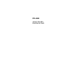
Chapter 1 Introduction
Figure 1-1: Switch and jumper layout
7
8
PCL-849 User's Manual
CHAPTER
Hardware
Installation
2
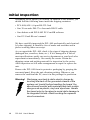
Initial Inspection
Depending on the option you ordered, in addition to this manual, you
should find the following items inside the shipping container:
• PCL-849(A/B/+) 4-port RS-232 Card
• One 30-cm male DB-37 to four male DB-25 cable
• One diskette with PCLS-802 PC-ComLIB software
• One PC-ComLIB user's manual
We have carefully inspected the PCL-849 mechanically and electrically before shipping. It should be free of marks and scratches and in
perfect working order on receipt.
As you unpack the PCL-849, check it for signs of shipping damage
(damaged box, scratches, dents, etc.). If it is damaged or it fails to
meet specifications, notify our service department or your local sales
representative immediately. Also notify the carrier. Retain the
shipping carton and packing material for inspection by the carrier.
After inspection we will make arrangements to repair or replace the
unit.
Remove the PCL-849 from its protective packaging by grasping the
rear metal panel. Keep the anti-vibration packing. Whenever you
remove the card from the PC, store it in this package for protection.
Warning! Discharge your body’s static electric charge by
touching the back of the grounded chassis of the
system unit (metal) before handling the board. You
should avoid contact with materials that hold a static
charge such as plastic, vinyl and styrofoam. Handle
the board only by its edges to avoid static damage to
its integrated circuits. Avoid touching the exposed
circuit connectors.
10
PCL-849 User's Manual
Card Installation
Warning! Turn off your PC’s power supply whenever you install
or remove the PCL-849 or its cables. Static electricity
can easily damage computer equipment. Ground
yourself by touching the chassis of the computer
(metal) before you touch any boards.
1. Turn off the computer. Turn the power off to any peripheral
devices (such as printers and monitors).
2. Disconnect the power cord and any other cables from the back of
the computer. Turn the PC if necessary to gain access to the
cables.
3. Remove the PC’s cover (refer to your user’s guide if necessary).
4. Locate the expansion slots or passive backplane (at the rear of the
PC) and choose any unused slot.
5. Remove the screw that secures the expansion slot cover to the PC
(save the screw to secure the interface card retaining bracket).
Remove the anti-vibration card clamp if supplied.
6. Carefully grasp the upper edge of the PCL-849 card. Align the
hole in the retaining bracket with the hole on top of the expansion
slot. Align the gold striped edge connector with the expansion slot
socket. Press the board firmly into the socket.
7. Replace the screw in the expansion slot retaining bracket. Replace
anti-vibration card holder.
8. Replace the PC’s cover. Connect the cables you removed in step 2.
9. Attach the DB-37 cable to the connector on the bracket. Turn the
computer power on.
The board is now installed in the computer. See Chapter 3 for information on cabling.
Chapter 2 Hardware Installation
11
Card Configuration
Each port on the PCL-849 card has a jumper and a DIP switch which
require configuring prior to use. The DIP switch sets the port to the
appropriate I/O address and speed mode. The jumpers set the port's
IRQ.
Default Settings
The board is shipped with default settings. If you need to change
these settings, however, see the following sections. Otherwise, you
can simply install the card. Note that you will need to disable your
CPU card's on-board COM ports, if any, or set them to alternate
addresses / IRQs.
PCL-849 Default Configuration
Setting
JPI
Default function
IRQ 12
Speed mode
1x
IRQ mode
Share
Base address
Address 300H
Vector address
Interrupt 280H
Interrupt mode
Enhance
I/O Address and Interrupt Setup
Next, you will need to select an IRQ (interrupt request) number, and
an I/O base address for the PCL-849.
Model Setup (base address setting)
The card base address can be set up using Mode 1. Please note that
the DIP switch is for mode setting as shown below.
12
PCL-849 User's Manual
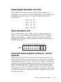
Standard Mode
In this mode, each of the four ports has been set up as an address, as
shown below.
Port 1
Ch1
base address
3F8
Port 2
Ch2
base address
2F8
Port 3
Ch3
base address
3E8
Port 4
Ch4
base address
2E8
Enhanced Mode
In this mode, each of the four ports has been set up as an address
individually. Select an address which is not already in use by another
card in the system. If you are installing more than one PCL-849 card
in your system, set the cards to different base adresses. DIP switches
control each card's base address, as shown below.
Port base address (S1)
Base Address
A3
A4
A5
A6
A7
A8
200-21F
l
l
l
l
l
l
208-227
¡
l
l
l
l
l
¡
l
¡
¡
¡
l
l
l
l
l
l
¡
l
l
¡
¡
¡
¡
··········
2E8-307
··········
*300-31F
··········
3E0-3FF
l: on
¡ : off
*= default
Chapter 2 Hardware Installation
13
Default Settings
Mode
Enhanced
Mode
Port 1
IRQ12
Address 300H
Port 2
IRQ12
Address 308H
Port 3
IRQ12
Address 310H
Port 4
IRQ12
Address 318H
The following example shows how to set the base address to 2F8.
The switch sum is set to 2F8: 200 + 80 + 40 + 20 + 10 + 8 (HEX).
Note: On the PCL-849 address line A9 does not appear on the DIP
switch, as it is permanently hardwired to hex 200.
Interrupt Level (IRQ) Setting
(S1, JP1, JP2, JP3, JP4)
The card's IRQ can be set up using S1. Please note that the DIP
switch is for setting the mode as shown below.
14
PCL-849 User's Manual
Independent IRQ Mode (JP1-JP4)
In this mode, each of the four ports can have IRQ channels set
individually. For each port, select an IRQ which is not already in use
by another card in the system. The map of jumpers and ports is
shown below.
Port 1 à JP1
Port 2 à JP2
Port 3 à JP3
Port 4 à JP4
Share IRQ Mode (JP1)
Select an IRQ which is not already in use by another card in the
system. If you are installing more than one PCL-849, set them to
different IRQ numbers. Jumper Bank JP1 controls the card IRQ.
Simply place the jumper on the required interrupt level as shown in
the following figure.
Interrupt Status Register Setup (S1, Vector
address)
This feature on the PCL-849 is utilized in the enhanced mode only.
When data arrives at one of the four ports, it will generate an interrupt
in the interrupt register. The PC software can read this, and identify
immediately which port generated the interrupt. This saves time, and
makes programming easier. When a data bit of the interrupt status
register is set to 0, the corresponding channel is selected to generate
an interrupt. If the bit is 1, then no interrupt is generated. DIP switch
S1 controls the card's interrupt status register, as shown in the following figure and table.
Chapter 2 Hardware Installation
15
Interrupt Status Register S1
Bit
Function
0
Port 1
1
Port 2
2
Port 3
3
Port 4
4
Not Used
5
Not Used
6
Not Used
7
Not Used
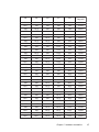
The user may change the interrupt status address via S1. Please note
that the address decoder will occupy a continuous, 16-byte area
related to the switch setting. For example, if you set the switch to
210H, then the address 210H to 21FH will all be decoded. The
various DIP switch settings (S1) for the interrupt status register are as
shown in the table opposite.
16
PCL-849 User's Manual
A4
A5
A6
A7
A8
Interrupt
Register
ON
ON
ON
ON
ON
200H
OFF
ON
ON
ON
ON
210H
ON
OFF
ON
ON
ON
220H
OFF
OFF
ON
ON
ON
230H
ON
ON
OFF
ON
ON
240H
OFF
ON
OFF
ON
ON
250H
260H
ON
OFF
OFF
ON
ON
OFF
OFF
OFF
ON
ON
270H
ON
ON
ON
OFF
ON
280H
OFF
ON
ON
OFF
ON
290H
ON
OFF
ON
OFF
ON
2A 0H
OFF
OFF
ON
OFF
ON
2B 0H
ON
ON
OFF
OFF
ON
2C 0H
OFF
ON
OFF
OFF
ON
2D 0H
ON
OFF
OFF
OFF
ON
2E 0H
OFF
OFF
OFF
OFF
ON
2F 0H
ON
ON
ON
ON
OFF
300H
OFF
ON
ON
ON
OFF
310H
ON
OFF
ON
ON
OFF
320H
OFF
OFF
ON
ON
OFF
330H
ON
ON
OFF
ON
OFF
340H
OFF
ON
OFF
ON
OFF
350H
ON
OFF
OFF
ON
OFF
360H
OFF
OFF
OFF
ON
OFF
370H
ON
ON
ON
OFF
OFF
380H
OFF
ON
ON
OFF
OFF
390H
ON
OFF
ON
OFF
OFF
3A 0H
OFF
OFF
ON
OFF
OFF
3B 0H
ON
ON
OFF
OFF
OFF
3C 0H
OFF
ON
OFF
OFF
OFF
3D 0H
ON
OFF
OFF
OFF
OFF
3E 0H
OFF
OFF
OFF
OFF
OFF
3F 0H
Chapter 2 Hardware Installation
17
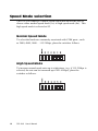
Speed Mode selection
The PCL-849 employs a unique speed option that allows the user to
choose either normal speed mode (1x) or high speed mode (8x). This
high speed mode is selected at S2.
Normal Speed Mode
To select the band rate commonly associated with COM ports , such
as 2400, 4800, 9600. . .115.2 Kbps, place the switch as follows.
High Speed Mode
To increase normal mode rates up to eight times, (e.g. if 115.2 Kbps is
selected, the rate can be increased up to 921.6 Kbps), place the
switches as follows.
18
PCL-849 User's Manual
CHAPTER
Software
Installation
3
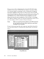
Operating Environment Selection
Set jumper 15 (JP15) to correspond with your desired software
operating environment. Connect the left two pins of JP15 to operate in
DOS or Windows 3.1 mode, as shown below. Connect the right two
pins to operate in Windows 95 or Windows NT mode .
1
JP15
DOS, Windows 3.1
1
JP15
Windows 95, Windows NT
Driver Installation for DOS Users
Make a duplicate copy of the driver diskette in case the original disk
becomes lost or damaged. Copy the files to a subdirectory on your
hard disk if you wish.
The PCL-849 comes with the PC-ComLIB software package. PCComLIB provides software drivers for DOS which supports most
common languages, including C, PASCAL, Visual BASIC, Quick
BASIC, Assembly and Clipper. PC-ComLIB also includes the
DataScope data viewer, terminal emulator and self-diagnostics
utilities for easy troubleshooting and debugging. Please see the PCComLIB manual for detailed information.
Card setup
The PCL-849's driver determines the configuration of the installed
cards by reading a data file, GEN-DRV.CNF. When you first install
the PCL-849, and each time you change the card's address and IRQ,
you will need to run the card setup program to save the settings to the
configuration file.
Program files should be installed to the hard disk. Insert the driver
disk in your computer, type DOSINST from the A: (or B:) prompt and
press enter. Once the files have been installed, type SETUP from the
\COMLIB\BIN prompt and press ENTER. You will then see the
screen on the following page.
20
PCL-849 User's Manual
Driver selection screen
After the screen shows up, move the cursor bar (using the arrow keys
or the mouse) to the general serial board field and press ENTER. The
screen shown below will appear.
Setup screen
Chapter 3 Software Installation
21
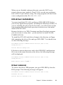
Here you can set the configuration for each of the PCL-849 cards
installed in the system. Set the IRQ, base address, baud rate, buffer
size and port number to match the card's configuration. Do this by
moving the highlight to the field you want to set up. Press ENTER
and a menu will appear, allowing you to select the correct setting. The
setup program also controls the port number assignments for each
card. When you use a driver function in your program, you will
identify the ports by these assignments. After you have set the IRQ,
base address, baudrate, buffer size and port assignments, press F10 to
save the settings or ESC to return to the previous page.
Note:
Make sure that the base address and IRQ selected
do not conflict with any other cards you may have
installed in your system.
If any of your ports have the same setup, you can define them all at
one time by pressing F5 to bring up the Group Setup screen shown
below.
Group Edit menu
22
PCL-849 User's Manual
When you are finished setting up the ports, press the ESC key to
return to the previous windows. Press F10 to save the new configuration or ESC to quit without saving. The setup program will then create
a new configuration data file GEN-DRV.CNF.
DOS driver installation
You must install the PCL-849 card driver (GEN-DRV.EXE) before
you run any application programs, including the DataScope utilities. If
you are installing the driver for the first time, you will need to run the
setup program (described in the previous section) to save the initial
status of the PCL-849.
Because the driver is a TSR (Terminate and Stay Resident) program,
you can execute it at any time – you do not have to install it in the
CONFIG.SYS file.
To install the PCL-849 card driver change to the directory or floppy
disk containing the driver files and type GEN-DRV. You should soon
see the following message:
PC-ComLIB Serial Communication Driver (Ver x.xx)
Setup driver...
Device driver setup O.K.
If the driver can not detect any card or the GEN.DRV configuration
file is not in the same directory as the driver, the following message
will be displayed:
PC-ComLIB Serial Communication Driver (Ver x.xx)
Setup driver...
None serial port found!!
Driver removal
To remove the driver TSR program, just type GEN-DRV/q from the
DOS prompt. The following message will appear:
PC-ComLIB Serial Communication Driver (Ver x.xx)
Release driver...
Device driver release O.K.
Chapter 3 Software Installation
23
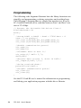
Programming
The following code fragment illustrates how the library functions can
simplify card programming, reducing setup time and avoiding bugs.
The following C program shows a simple data transfer test. It uses a
PC-ComLIB function call to send data between Port 1 and Port 2 at a
rate of 57.6 Kbps.
/* Execute the PC-ComLIB TSR driver first*/
#include<head-c.h>
main()
{
/*Setup PORT1 & PORT2 : baud = 57600 data = 8
stop = 1 no parity*/
sio_ioctl(1,B57600,BIT_8|P_NONE|STOP_1);
sio_ioctl(2,B57600,BIT_8|P_NONE|STOP_1);
/*Enable communication ports*/
sio_open(1);
sio_open(2);
/*Transmit data on Port 1*/
sio_write(1," Hello ",7);
delay(200)
/*Receive data on Port 2, store in buf1*/
sio_1input(2,buf1,7,13);
/*Print received data*/
printf("%s\n",buf1);
/*Disable communication ports*/
sio_close(1);
sio_close(2);
}
See the PC-ComLIB user’s manual for information on programming
and linking your application programs with the driver libraries.
24
PCL-849 User's Manual
Driver Installation for Windows 3.1 Users
Windows 3.1 provides a versatile and easily configurable interface
that supports up to four COM ports with a standard driver. The PCComLIB Standard Windows COMM Driver, along with PCL-849,
allow users to install up to six serial ports under Windows 3.1.
The Standard Windows COMM Driver supports Microsoft Windows
COMM API (Application Programming Interface) such as OpenComm(), ReadComm(), and WriteComm(). Application software like
Windows Terminal program, LabVIEW, FIX, and pcANYWHERE
for Windows, or other programs that support Windows COMM API
calls can communicate to the outside world via PCL-849 multiport
boards.
Installing the Standard Windows COMM Driver
1. Insert the PC-ComLIB diskette into the floppy drive A: (or B:).
2. In Windows File Manager, execute A:\WININST (or
B:\WININST).
A Driver Installation window will appear.
Driver Installation window
3. Choose the board type, driver type, and the working directory to
which the software will be copied when using PCL-849.
Chapter 3 Software Installation
25
A maximum of 6 ports is supported if the existing standard COM
ports (COM1 and COM2) are included. For example, you can set one
serial port on the motherboard for COM1 (0x3F8, IRQ4), while
designating COM2-5 on IRQ3 for the four ports on a PCL-849 card.
Note:
If using a serial mouse, it must be installed on either
COM1 (0x3F8, IRQ4) or COM2 (0x2F8, IRQ3), and
must have its own dedicated IRQ.
The utility TTY, which can manipulate ports from COM1 to COM9,
is included to help users monitor and debug RS-232 communications
under Windows 3.x . It is a simple example program capable of
sending and receiving data after each port is opened with selected
communication parameters. As Windows 3.x features multitasking,
multiple windows for the ports can appear simultaneously under TTY.
However, Terminal, the application provided by Windows is limited
for the use of COM1 to COM4.
After completing the installation, restart Windows. An additional line,
"comm.drv=sercomm.drv", will appear for the PCL-849 in the [boot]
section of the Windows SYSTEM.INI file. In addition, a Windows
group "PC-ComLIB Standard COMM Driver" will be generated for
reconfiguration, driver removal, etc. At this point, you are ready to
execute applications that support Windows COMM API calls.
Installation for Windows 95
Environment
Windows 95 supports up to128 serial ports, from COM1 to COM128,
in the Windows 95 environment. To fully integrate the advanced
features of Windows 95, such as multi-processing and multi-threading, configure Windows 95 as described below:
1.Enter [My Computer], then [Control Panel], then [Add New
Hardware].
2.Enter [Next], then choose [N]ot to do an auto search for new
hardware.
26
PCL-849 User's Manual
3.Enter [Next], then choose [Connection Port (COM & LPT)]
Hardware Type.
4.Enter [Next], then select [Standard Connection Port Type] for
manufacturer and [Communication Connection Port] for model.
5.Enter [Next], then the default IRQ and I/O Addresses will be
shown. Click [Done].
Up to this point you have added a port to the system without correcting IRQ and I/O settings. You can repeat step 1 to step 5 to add as
many ports as you want (Max. 128 port).
6.Enter [Control Panel], then [System], then [Device Manager].
7.Select the newly added [Communication port (COMn)], where n
is a new port number, then [Resource].
8.Select the ??? as [Basic Configure 8].
9.Double Click on IRQ and type in (select) the hardware IRQ, then
[OK].
10.
Double Click on I/O range and type in (select) the hardware I/O, then [OK].
Repeat steps 6 through 10 to setup each port correctly.
11.
Click [OK].
12.
Restart Windows 95 to initialize the new settings.
Chapter 3 Software Installation
27
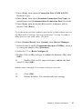
Installation for Windows NT Environment
Windows 95 supports up to256 serial ports, from COM1 to COM256,
in the Windows NT environment. To fully integrate the advanced
features of Windows 95, including multi-processing and multithreading, configure Windows 95 as described below:
1.Enter Control Panel and choose Ports to add new COM ports.
2.Add new ports using the command sequence given in the following
example. If you wanted to add the 4 new ports COM3 ~ COM6
listed below, you would add each port using the following command list: S2 è 300h, JP1 è IRQ7, MODE 0 è Share IRQ Mode
(DIP ON), MODE 1 è Enhance Mode (DIP OFF). Make sure no
other devices use the same system resources.
Port 1: Base Address 300h + 00h,
IRQ 5
Port 2: Base Address 300h + 08h,
IRQ 5
Port 3: Base Address 300h + 10h,
IRQ 5
Port 4: Base Address 300h + 18h,
IRQ 5
Restart Windows NT to initialize the new settings.
28
PCL-849 User's Manual
CHAPTER
Wiring
4
Chapter 4 Wiring
29
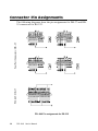
Connector Pin Assignments
PCL-849: DB-37
Four Port Connectors: DB-25
The following diagrams show the pin assignments for DB-37 and DB25 connectors for RS-232.
PCL-849 Pin assignments for RS-232
30
PCL-849 User's Manual
Wiring
RS-232 signal wiring
Since the RS-232 interface is not strictly defined, many devices have
their own connection methods which may ignore some signal lines or
define reserved lines for other functions. It is best to refer to the user’s
manual for your device for installation instructions. You may find the
following helpful.
In general, DTE (Data Terminal Equipment) refers to the device that
is leading the communication. Examples include PC’s, terminals and
some printers. DCE refers to the device being communicated with or
controlled. Examples include modems, DSU’s (digital service units),
printers and lab/factory equipment.
In some situations you may be able to get by with just three lines: data
on TXD, a signal ground and a handshaking line. Examples are printer
or plotter connections, troubleshooting and situations where you
require only one-wire communication.
Terminal or PC (DTE) connections
DB-25 Male: PCL-849
DB-25 Male or Female:
Terminal
Pin
2
Pin
3
Signal
TxD
Signal
RxD
3
RxD
2
TxD
4
RTS
5
CTS
5
CTS
4
RTS
6
DSR
20
DTR
7
GND
7
GND
20
DTR
6
DSR
8
DCD
8
DCD
Chapter 4 Wiring
31
Modem connections
DB-25 Male: PCL-849
Modem (DCE)
Pin
2
Pin
2
Signal
TxD
Signal
RxD
3
RxD
3
TxD
4
RTS
4
CTS
5
CTS
5
RTS
6
DSR
6
DTR
7
GND
7
GND
20
DTR
20
DSR
8
DCD
8
DCD
For DTE to DCE connection, use straight through cable, i.e. you don't
have to reverse lines 2 and 3, lines 4 and 5, and lines 6 and 20.
Because in general the DCE RS-232 interfaces are reversed themselves.
Terminal without handshake
DB-25 Male: PCL-849
Terminal, PC (DTE)
Pin
2
Signal
TxD
Pin
3
Signal
RxD
3
RxD
2
TxD
4
5
RTS
CTS
7
GND
7
GND
6
20
8
DSR —
DTR
—
DCD —
—
—
If not using CTS, RTS, DSR ,DTR signals, please loop back for the
PC-ComLIB software to function correctly, because PC-ComLIB will
always check for handshake signals.
32
PCL-849 User's Manual
APPENDIX
PC I/O Address
Reference
A
Appendix A PC I/O Address Assignments
33
PC I/O Address Usage
The following table indicates the PC I/O address usage assignment.
To prevent conflicting settings of the PCL-849 with other devices or
I/O cards, you are recommended to refer this table.
34
I/O Address
Device
000 - 00F
DMA (8237A)
020 - 021
8259A IRQ Controller
040 - 043
8253/8254 Timer/Counter
060 - 063
PPI 8255A
070 - 071
Real-Time Clock
080 - 08F
DMA Page Register
0A0 - 0BF
8259A Interrupt Chip
0C0 - 0DF
Second DMA Controller 8237A
0F0 - 0FF
Math Coprocessor
1F0 - 1F8
AT Fixed Disk
200 - 20F
Game I/O
278 - 27F
Parallel Printer Adaptor #2
2F8 - 2FF
Serial Adaptor ( COM 2 )
320 - 32F
XT Fixed Disk
378 - 37F
Parallel Printer Adaptor #1
380 - 38F
SDLC Binary Communication Adaptor
3A0 - 3AF
Master Binary Communication Adaptor
3B0 - 3BF
Monochrome/Parallel Adaptor
3D0 - 3DF
Color Graphics Adaptor
3F0 - 3F7
Diskette Controller
3F8 - 3FF
Serial Adaptor ( COM 1 )
PCL-849 User's Manual
APPENDIX
Quick
Reference
B
Appendix B Quick Reference
35
Ø Jumper Setting
·
IRQ Mode
DIP 1 (MODE 0) of S1 is used to set the IRQ mode of this card.
DIP1 : ON (Upper) position
è Share IRQ mode
DIP1 : OFF (Lower) position
è Independent IRQ mode
·
STANDARD/ ENHANCED Mode
DIP 2 (MODE 1) of S1 is used to set the Standard/enhanced mode of
this card.
DIP1 : ON (Upper) position
è STANDARD mode
DIP1 : OFF (Lower) position
è ENHANCED mode
·
STANDARD/ ENHANCED Mode
DIP 1 (SPEED) of S2 is used to decide the speed mode of this card.
Ø Operating System Mode
Connect the left two pins of JP15 to use DOS, Windows 3.1
Connect the right two pins of JP15 to use Windows 95, NT
Ø High Speed Mode (Frequency of Oscillator Crystal = 14.7456
MHz) è Speed Bit on S2 is ON
DIP1 : ON (Upper) position è High Speed Mode or ´ 8 Mode
(Frequency of Oscillator Crystal = 14.7456 MHz)
36
PCL-846/847 User's Manual
DIP1 : OFF (Lower) position è Normal Speed Mode
(Frequency of Oscillator Crystal = 1.8432 MHz)
STANDARD MODE: In this mode, The I/O Addresses and its IRQ
Level for each port are set to default as shown below, (Disable BIOS
setting of on-board COM1 ~ COM4)
Po r t N o .
I/O Ad d r es s
COM Po r t
No .
IRQ L ev el (*)
Independent IRQ
Share IRQ
Port 1
3F 8h
COM1
JP 1
JP 1
Port 2
2F 8h
COM2
JP 2
JP 1
Port 3
3E 8h
COM3
JP 3
JP 1
Port 4
2E 8h
COM4
JP 4
JP 1
ENHANCED MODE: In this mode, The I/O Addresses and its IRQ
Level for each port are set to default as shown below, (Make sure that
the I/O address on BIOS setting of on-board COM1 ~ COM4 will
never conflict with [Base Address] ~ [Base Address + 20h])
Po r t N o .
Port 1
Port 2
Port 3
Port 4
I/O Ad d r es s
Base Address
+ 00h
Base Address
+ 08h
Base Address
+ 10h
Base Address
+18h
COM Po r t
No .
IRQ L ev el (*)
Independent IRQ
Share IRQ
COM1
JP 1
JP 1
COM2
JP 2
JP 1
COM3
JP 3
JP 1
COM4
JP 4
JP 1
Appendix B Quick Reference
37
38
PCL-846/847 User's Manual