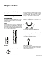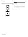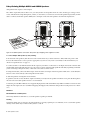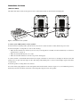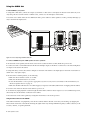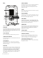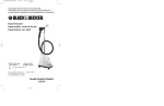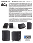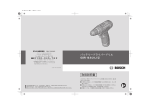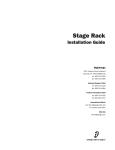
1
GSR Speakers Guide Legal Notices This guide is copyrighted ©2010 by Avid Technology, Inc., with all rights reserved. Under copyright laws, this guide may not be duplicated in whole or in part without the written consent of Avid Technology, Inc. Avid and M-Audio are either trademarks or registered trademarks of Avid Technology, Inc. All other trademarks contained herein are the property of their respective owners. Product features, specifications, system requirements, and availability are subject to change without notice. Guide Part Number 9320-65007-00 REV B 07/10 Documentation Feedback We are always looking for ways to improve our documentation. If you have comments, corrections, or suggestions regarding our documentation, email us at [email protected]. Warranty Terms M-Audio warrants products to be free from defects in materials and workmanship, under normal use and provided that the product is owned by the original, registered user. Visit www.m-audio.com/warranty for terms and limitations applying to your specific product. Warranty Registration Thank you for registering your new M-Audio product. Doing so immediately both entitles you to full warranty coverage and helps M-Audio develop and manufacture the finest quality products available. Register online at www.m-audio.com/register for the chance to win M-Audio giveaways. Contents Chapter 1. Introduction . . . . . . . . . . . . . . . . . . . . . . . . . . . . . . . . . . . . . . . . . . . . . . . . . . . . . . . . . . . . . . . . . . . . . . . . . . . 1 Chapter 2. Setups . . . . . . . . . . . . . . . . . . . . . . . . . . . . . . . . . . . . . . . . . . . . . . . . . . . . . . . . . . . . . . . . . . . . . . . . . . . . . . . . 3 Speaker Positioning . . . . . . . . . . . . . . . . . . . . . . . . . . . . . . . . . . . . . . . . . . . . . . . . . . . . . . . . . . . . . . . . . . . . . . . . . . . 3 AC Power . . . . . . . . . . . . . . . . . . . . . . . . . . . . . . . . . . . . . . . . . . . . . . . . . . . . . . . . . . . . . . . . . . . . . . . . . . . . . . . . . . . 4 Setup Diagrams . . . . . . . . . . . . . . . . . . . . . . . . . . . . . . . . . . . . . . . . . . . . . . . . . . . . . . . . . . . . . . . . . . . . . . . . . . . . . . 5 Chapter 3. Hardware Overview . . . . . . . . . . . . . . . . . . . . . . . . . . . . . . . . . . . . . . . . . . . . . . . . . . . . . . . . . . . . . . . . . . . . . 9 GSR10 and GSR12 . . . . . . . . . . . . . . . . . . . . . . . . . . . . . . . . . . . . . . . . . . . . . . . . . . . . . . . . . . . . . . . . . . . . . . . . . . . . 9 GSR18 . . . . . . . . . . . . . . . . . . . . . . . . . . . . . . . . . . . . . . . . . . . . . . . . . . . . . . . . . . . . . . . . . . . . . . . . . . . . . . . . . . . . 11 Appendix A. Technical Specifications . . . . . . . . . . . . . . . . . . . . . . . . . . . . . . . . . . . . . . . . . . . . . . . . . . . . . . . . . . . . . . 13 GSR10 . . . . . . . . . . . . . . . . . . . . . . . . . . . . . . . . . . . . . . . . . . . . . . . . . . . . . . . . . . . . . . . . . . . . . . . . . . . . . . . . . . . . 13 GSR12 . . . . . . . . . . . . . . . . . . . . . . . . . . . . . . . . . . . . . . . . . . . . . . . . . . . . . . . . . . . . . . . . . . . . . . . . . . . . . . . . . . . . 14 GSR18 . . . . . . . . . . . . . . . . . . . . . . . . . . . . . . . . . . . . . . . . . . . . . . . . . . . . . . . . . . . . . . . . . . . . . . . . . . . . . . . . . . . . 15 Appendix B. Compliance Information . . . . . . . . . . . . . . . . . . . . . . . . . . . . . . . . . . . . . . . . . . . . . . . . . . . . . . . . . . . . . . 17 Environmental Compliance. . . . . . . . . . . . . . . . . . . . . . . . . . . . . . . . . . . . . . . . . . . . . . . . . . . . . . . . . . . . . . . . . . . . . . 17 EMC (Electromagnetic Compliance). . . . . . . . . . . . . . . . . . . . . . . . . . . . . . . . . . . . . . . . . . . . . . . . . . . . . . . . . . . . . . . . 17 Safety Compliance . . . . . . . . . . . . . . . . . . . . . . . . . . . . . . . . . . . . . . . . . . . . . . . . . . . . . . . . . . . . . . . . . . . . . . . . . . . 18 Contents iii iv GSR Speakers Guide Chapter 1: Introduction Welcome to the M-Audio GSR series of active loudspeakers. The GSR series loudspeakers have been designed from the ground up to provide stunning sound every time, everywhere, and includes the following three speakers: GSR10 Active two-way, sound reinforcement speaker with one 10-inch woofer, and one 25mm compression driver. Features GSR10 and GSR12 • Amplification: Class D, Bi-amped • GSR10 LF: 200W, HF: 50W • GSR12 LF: 250W, HF: 50W • Tuning mode Presets: GSR12 Active two-way sound reinforcement speaker with one 12-inch woofer, and one 34mm compression driver. • Normal GSR18 Active subwoofer speaker with 18-inch woofer. • DJ • Hi-Fi • Voice • XLR/TRS combo input • Mic/Line selector • High-pass filter • Built-in limiter protection circuit • Thru (output) XLR jack • Automatic input voltage sensing (110V – 240V) • Portable and flexible GSR18 • Amplification: Class D, 500W • Stereo XLR/TRS combo inputs • Variable low-pass Frequency control • Phase invert • Thru (output) XLR jacks • Automatic input voltage sensing (110V – 240V) For setup and connection instructions, see Chapter 2, “Setups.” For more information on the front and back panel features of each speaker, see Chapter 3, “Hardware Overview.” Chapter 1: Introduction 1 2 GSR Speakers Guide Chapter 2: Setups This chapter shows how to set up and power your GSR speakers, and provides audio connection diagrams of a few typical setups. Flown Speaker Positioning For suspension mounting or “flying” your GSR10 and GSR12, there are five (5) M10 flypoints located on the top, bottom, and back of the cabinet. Simply thread in a corresponding M10 eye-bolt, and you’re ready for “flying” your GSR full-range cabinets. GSR10 and GSR12 To access the M10 flypoints: GSR speakers can be positioned standing upright, as a floor wedge monitor, flown, or mounted on a standard speaker stand (not included). On the top, bottom, and rear of the cabinet, remove the threaded caps that cover the M10 inserts. Standing When positioned on the floor standing up straight, the speakers can be stacked (never stack more than two GSR speakers). When stacking a speaker, make sure its feet align properly on the top of the lower speaker using the interlock feature on the tops of the GSR10 and GSR12 cabinets. 1 1 Top view of GSR10 (or GSR12) showing M10 flypoint inserts Mounted Each GSR10 and GSR12 features a 36mm pole mount receptacle on the bottom, enabling you to mount the speaker on any standard 1 3/8-inch speaker stand. After mounting a speaker on any pole or stand, be sure to hand-tighten the rear stabilizing screw on the back of the cabinet. This ensures the cabinet does not move or turn during performance. GSR12 standing straight (left) and stacked (right) Floor Wedge GSR10 mounted on a pole stand The GSR10 and GSR12 also have 45° angled sides that let you lean it back on itself, like a typical “floor wedge” monitor. The GSR18 subwoofer has a 1 3/8-inch pole mount on its top, letting you use a standard speaker pole to mount a GSR10 or GSR12 directly on top of a GSR18. GSR10 leaned back to use as a floor wedge monitor Chapter 2: Setups 3 GSR18 The GSR18 should be placed on the floor or stage. Do not stack speakers directly on top of the GSR18 unless you are using the pole mounts and one GSR10 or GSR12. AC Power (All GSR Models) GSR speakers provide automatic input voltage sensing (110V to 240V). To connect power to a GSR speaker: Connect the included AC power cable to the AC Input in the back of the speaker. Connect the other end to your wall outlet or other power source. GSR10 mounted on a GSR18 4 GSR Speakers Guide Setup Diagrams Connecting a Microphone (GSR12 and GSR10 Only) The Figure below shows how a microphone can be connected directly to a GSR12 or GSR10 using an XLR or TRS cable. 3 1 4 2 Figure 1. Microphone connected to the Mic input (GSR12 shown) To use a GSR12 or GSR10 with a single microphone: 1 On the back of the speaker, turn the Level control down (counter-clockwise to Min). Make sure power is Off. 2 Using an XLR or TRS cable, connect a dynamic microphone to the Input on the back of the speaker. 3 Make sure the Mic/Line button is set to the Mic position. 4 Rotate the Mode knob to select Voice mode (you can change this later, but we recommend it for voice and speech). For more information on the tuning presets, see “Modes for Speaker Presets” on page 11. 5 Turn the speaker on using the Power switch. 6 Speak into the mic while you slowly raise the Level. Don’t point the microphone at the front of the speakers to avoid feedback. 7 If desired, press the HPF 75Hz button to engage the high-pass filter. The HPF (high-pass filter) can reduce or eliminate rumble and other low-end noise. Chapter 2: Setups 5 Daisy-Chaining Multiple GSR10 and GSR12 Speakers GSR speakers have outputs as well as inputs. The “Thru” output XLR jacks are there to let you “daisy-chain” several speakers from one source. In this type of setup, a mono source (whether from a single microphone, a mixer, or other device) is connected to the first GSR speaker’s Input. Then, an XLR cable is connected from that speaker’s THRU jack to the Input on the next GSR speaker as shown in the figure below. 1 3 2 1 2 4 Figure 2. Two GSR12 speakers connected in “daisy-chain” style, amplifying a mono signal from a mixer. To connect multiple GSR speakers by daisy-chaining: 1 On the back of the speakers, turn the Level control down all the way (counter-clockwise to Min). Make sure power is Off. 2 Rotate the Mode knobs to select a preset as appropriate (if you’re not sure, leave it at Normal). For more information, see “Modes for Speaker Presets” on page 11. 3 Connect an XLR or 1/4-inch TRS cable from the output of your mixer or other device to the Input on the back of the first GSR speaker. Make sure the Mic/Line button is set to the correct position on the first GSR speaker in each chain, depending on whether you’re connecting a microphone (Mic) or line level source such as a mixer (Line). 4 Using an XLR cable, connect the Thru output on the first GSR to the Input on the next speaker. Make sure to set the Mic/Line button to Line on this and any other GSR speakers in the chain. 5 Turn the speakers on using their Power switches. 6 Speak into the mic or raise the mixer output level while you slowly raise the speaker Level knob. Don’t point the microphone into the front of the GSR speakers in order to avoid feedback. 7 If desired, press the HPF 75Hz button to engage the high-pass filter. This can eliminate any rumble or similar low-end noise that might enter the signal. (We also recommend engaging the high-pass filter when the GSR speakers are being used as floor monitors.) Guidelines Maximum Number of GSR Speakers Never daisy-chain more than three (3) total GSR speakers together per channel. Stacking If using the GSR18 sub, you can raise one GSR speaker above it using a speaker pole (not included). Do not stack other speakers directly on the GSR18 sub, as vibrations may cause it to fall off. 6 GSR Speakers Guide Connections for Stereo (GSR12 and GSR10) The GSR12 and GSR10 can be used in pairs for stereo sound reinforcement as shown in the following figure. 1 3 2 1 2 3 Figure 3. Connections for stereo operation To connect a pair of GSR speakers for stereo operation: 1 On the back of both GSR speakers, turn the Level control down (counter-clockwise to Min). Make sure power is Off. 2 On the back panel of each speaker, do each of the following: • Make sure the same Mode is selected (if you’re not sure, set both speakers to Normal). For more information, see “Modes for Speaker Presets” on page 11. • Make sure the Mic/Line button is set to Line. • Make sure the HPF 75Hz button is in the out position (disengaged). 3 Connect an XLR or 1/4-inch TRS cable from the Left output of the mixer or other device to the Input on the back of the GSR speaker you’ve set up for the left. Repeat for the other GSR speaker, making sure to source it from the Right output of the mixer or other device. 4 Turn the speakers on using their Power switches. 5 To check levels, begin playback of audio through the mixer with its mains or master output set to its recommended position, then slowly raise the Level knob on the back of the GSR speaker. Repeat for the other speaker. Chapter 2: Setups 7 Using the GSR18 Sub To add a GSR18 to your system: Using XLR or TRS cables, connect the output of your mixer or other device to the Inputs on the back of the GSR18. If you’re only using a mono feed from a mixer or similar source, connect it to the Left Input on the GSR18. You can also use a GSR18 subwoofer in combination with a pair of GSR12 or GSR10 speakers to form a powerful, full-range system, as shown in the figure below. 2 2 5 1 5 3 3 4 Figure 4. Stereo setup using a GSR18 subwoofer To connect a GSR18 and a pair of GSR speakers for stereo operation: 1 On the back of each speaker, turn the Level control down (counter-clockwise to Min). Make sure power is Off. 2 Connect two XLR or 1/4-inch TRS cables from the Left and Right outputs of the mixer or other device to the Left and Right Ste- reo Inputs on the back of the GSR18. 3 Using XLR cables, connect the L/R Stereo Outputs on the back of the GSR18 to the Input input on the back of each GSR10 or GSR12 (left to left, right to right). 4 On the GSR10 or GSR12 speakers, do the following: • Make sure the Level knob is down (set to Min). • Make sure the Mic/Line button is set to Line. • Rotate the Mode knob to select a preset as appropriate (if you’re not sure, leave it at Normal). For more information, see “Modes for Speaker Presets” on page 11. • Make sure the HPF 75Hz button is “in” (HPF engaged) to keep bass from GSR10/GSR12 from overlapping with the GSR18. 5 Use the Power switch on the back of the GSR18 to power it on. 6 To check levels, begin playback of audio through the mixer with its Mains or master output set to its recommended position, then slowly raise the Level knob on the back of the GSR18. 7 Raise the levels on the other speakers by setting their Level knobs to the desired position. Using the Phase Switch on the GSR18 If the GSR18 Level knob is up high but you’re still not satisfied with the amount of low-end you’re hearing, try engaging the Phase switch on the back of the GSR18. Inverting the signal in this way can help minimize frequency conflicts caused by room acoustics, distance, or speaker placement. 8 GSR Speakers Guide Chapter 3: Hardware Overview This chapter describes the connectors and hardware features of the following GSR speakers: • “GSR10 and GSR12” on page 9 • “GSR18” on page 11 HF Driver and Horn GSR10 25mm titanium compression driver. GSR12 34mm titanium compression driver. Front Grille GSR10 and GSR12 The GSR10 and GSR12 both use the same type of amplifier and provide the same front and back panel features. These common features are described in the following sections. (For the GSR18, see “GSR18” on page 11.) Do not block or remove the front grille. LF Driver GSR10 10-inch neodymium motor driver. GSR12 12-inch neodymium motor driver. Front Top, Sides, and Bottom Handles (Top and Side) Handles are provided on the top and sides for carrying the speakers. Feet Feet are provided on the bottom of the cabinets for standing on the floor or stacking. These rubber feet acoustically decouple the speaker from the surface it is sitting on, and prevent the speaker from moving due to vibration. M10 Flypoints Front of the GSR10 (left) and GSR12 (right) The GSR10 and GSR12 both provide M10 inserts for flypoints and rigging on the top, bottom, and back of the cabinet. Pole Mount This socket, found on the bottom of the GSR speakers, is a standard 1 3/8-inch (36mm) pole mount that lets you mount the speaker on a stand (or on a pole inserted into the pole mount receptacle found on the top of the GSR18). Chapter 3: Hardware Overview 9 Back 6 Mic/Line Button The Mic/Line button lets you choose an Input operating level between Mic or Line levels. When a single XLR microphone/cable is plugged into the GSR speaker, this switch should be set to Mic. 7 Level 1 The Level knob controls the amount of attenuation or gain applied to the input signal. 5 2 6 10 11 12 3 4 7 8 8 Input (XLR/TRS) The Input jack is where you connect a microphone, or the outputs from a mixer or other device. This jack allows for either XLR or TRS (1/4-inch) input connections. 9 Thru Output The Thru jack is an output for daisy-chaining multiple GSR speakers. Use an XLR cable to connect this Thru jack to the Input on another GSR10 or GSR12. The Thru output bypasses (is unaffected by) HPF and Mode selection. 9 13 10 Mode Knob GSR10 / GSR12 back 1 Heat Sink The aluminum amplifier panel doubles as a heat sink, which dissipates heat generated by the GSR amplifier. Do not block the heat sink, and make sure nothing comes in direct contact with it while powered on. 2 Power Indicator The Power LED lights green when the GSR is powered on. 3 Signal Present Indicator The Signal LED lights green to indicate when the GSR is receiving an input signal. 4 Peak Indicator The Peak LED flashes red to indicate that the speaker has clipped; lower the source, or turn the speaker down using its back panel Level knob. 5 HPF 75Hz The HPF 75Hz button engages/disengages the high-pass filter (HPF). When pressed (button is “in”), the GSR speaker engages a 24 dB per octave high-pass filter to reduce or eliminate low-end rumble being picked up by microphone inputs (or any noise below 75Hz). When you’re also using a GSR18 sub, we recommend engaging the HPF on all satellite GSR10 or GSR12 speakers. 10 GSR Speakers Guide The Mode knob lets you select among four different presets to “tune” the GSR speaker and optimize its performance in different situations. For more information, see “Modes for Speaker Presets” on page 11. 11 Power Switch The Power switch turns the GSR speaker on/off. 12 AC Power and Fuse This socket accepts a standard IEC power cable (one is included) for AC power to the speaker. The fuse protects the speakers from damage due to power spikes and surges. 13 Pole Mount Stabilizing Screw This secures the GSR10 or GSR12 to a pole, when mounting the speaker on a stand. Modes for Speaker Presets GSR10 and GSR12 speakers provide a Mode selector on the back panel that allows you to choose one of four speaker modes. GSR18 Front Each mode, described below, is a “tuning” preset that optimizes the response of the GSR speakers for different situations. The differences between modes can be subtle at lower volumes, but become more pronounced the louder the speaker is used. Normal Normal mode is the default mode (factory set), and is the best all-around “flat” setting. Use this mode for the best overall sound for all types of material (voice as well as music). Hi-Fi In Hi-Fi mode, highs and lows are boosted slightly while mids are cut by a few dB to heighten presence, even at low volume. This mode is optimized for audio playback (such as from a CD player). GSR18 front LF Driver DJ 18-inch subwoofer (500W). DJ mode emphasizes the low-end and tailors the mids and highs for clarity and punch, even at moderate and high volume. This mode has been optimized for DJ live performance. Front Grille The perforated steel grille is to protect the 18-inch woofer. Do not block or remove front grille. Voice Use Voice mode when you’ve connected a microphone directly to a GSR10 or GSR12 speaker. Voice mode is high-pass filtered at 90 Hz, and gives a slight boost to the frequencies of the human voice to maximize intelligibility, even at lower volume levels. This mode is perfect for boardroom presentations or public address applications. The GSR10 and GSR12 also provide a high-pass filter on the Mic input. For more information, see “5 HPF 75Hz” on page 10. Pole Mount The top of the GSR18 provides a mounting socket that accepts a standard speaker pole (1 3/8-inch (36mm)). Use this mount to secure a standard speaker pole (not included) in order to mount a GSR10 or GSR12 on the sub. Handles Handles are provided on both sides of the GSR18. We recommend using two people when lifting or carrying the sub. Feet Don’t remove the feet or casters. Always place the GSR18 upright (not on its side). Casters (Wheels) The GSR18 is equipped with removable casters that are mounted to the amplifier side of the subwoofer for easy transportation. Chapter 3: Hardware Overview 11 Back 5 Left/Right Stereo Inputs 1 2 3 4 These input jacks are for connecting XLR or 1/4-inch TRS cables from the left and right outputs of a mixer of other stereo source. If you are connecting a mono source, use the Left input (XLR, or TRS). 6 Left/Right Stereo XLR Thru Outputs The Thru jacks provide a stereo pair of XLR outputs to connect to the inputs of other GSR speakers. 8 7 6 5 9 7 Level 10 The Level knob controls the volume of the GSR18. 8 Phase GSR18 back 1 Heat Sink The aluminum amplifier panel doubles as a heat sink, which dissipates heat generated by the GSR amplifier. Do not block the heat sink, and make sure nothing comes in direct contact with it while powered on. The Phase switch lets you alter the polarity of the input signal. When the Phase switch is in its default “out” setting, phase is unaffected. When “in” the signal is adjusted 180°. Try enabling the Phase switch if the overall sound in the particular room seems like it’s “collapsing” when turned up. This can sometimes occur when a sub is positioned off to the side, behind a curtain, or in applications where the subwoofer is not firing in the same direction as the full-range speakers. 9 Frequency 2 Power Indicator LED The Power LED lights green when the GSR18 is powered on. 3 Signal Present Indicator LED The Signal LED lights green to indicate when the GSR is receiving an input signal. 4 Peak Indicator LED The Peak LED flashes red to indicate that the speaker has clipped; lower the source, or turn the speaker down using its Volume control. The variable low-pass Frequency knob lets you dial in the ideal frequency to crossover to your full-range “tops” such as the GSR10 or GSR12, to maximize bass output. Since the GSR10 and GSR12 both have a 75 Hz high-pass button, the ideal frequency to crossover to the “tops” would be 75 Hz. However, all listening environments, “tops” from other manufacturers, and personal tastes are different. So, depending on the placement of the GSR18 and how much bass is desired, the Frequency knob (along with the Phase button) lets you optimize the bass response for any room or application. 10 AC Power and Fuse This socket accepts a standard IEC power cable (one is included) for AC power to the speaker. The fuse protects the speakers from possible damage due to power spikes or surges. If you ever need to replace the fuse, you can do so by removing the fuse cover, taking out the old fuse and installing a new one. Always replace the fuse with one of the same rating. Location of fuse 12 GSR Speakers Guide Appendix A: Technical Specifications GSR10 Type Active two-way bass reflex design Frequency Response +/– 3 dB: 72 Hz to 16 kHz (Mode set to Normal) Frequency Range 57 Hz to 18 kHz (–10 dB) (Mode set to Normal) Crossover Pattern: 90° H x 60° V nominal Crossover Frequency: 2.8 kHz 24 dB/octave 4th-order alignment System Power Rating 250 W continuous, 500 W peak Maximum SPL 121 dB Nominal Impedance 8 Ohms LF Driver 10-inch (254mm) neodymium magnet woofer with 2 1/2-inch voice coil 200 W continuous at driver impedance HF Driver 1-inch (25mm) titanium diaphragm, neodymium magnet compression driver 50 W continuos at driver impedance High-Pass Filter (HPF) 75 Hz Input Balanced XLR/TRS (1/4-inch) combo jack with XLR loop through Pole Socket 1 3/8-inch (36mm) pole mount socket with stabilizing screw Mounting 5 x M10 suspension points (2 bottom, 2 top, 1 rear) AC Input 220–240 VAC ~ 50 Hz 100–120 VAC ~ 60 Hz Dimensions (H x W x D) 21.9” x 13.7” x 11.2” (55.62cm x 34.8cm x 28.45cm) Net Weights 25 lbs (11.3 kg) Above specifications subject to change without notice Appendix A: Technical Specifications 13 GSR12 Type Active two-way bass reflex design Frequency Response +/– 3 dB: 53 Hz to 20 kHz (Mode set to Normal) Frequency Range 42 Hz to 22 kHz (–10 dB points) (Mode set to Normal) Crossover Pattern: 90° H x 60° V nominal Crossover Frequency: 2.8 kHz 24 dB/octave 4th-order alignment System Power Rating 300 W continuous, 600 W peak Maximum SPL 127 dB Nominal Impedance 8 Ohms LF Driver 12-inch (30.48cm) neodymium magnet woofer with 2 1/2-inch voice coil 250 W continuous at driver impedance HF Driver 1.3-inch (34mm) titanium diaphragm compression driver 50 W continuous at driver impedance High-Pass Filter (HPF) 75 Hz Input Balanced XLR/TRS (1/4-inch) combo jack with XLR loop through Pole Socket 1 3/8-inch (36mm) pole mount socket with stabilizing screw Mounting 5 x M10 suspension points (2 bottom, 2 top, 1 rear) AC Input 220–240 VAC ~ 50 Hz 100–120 VAC ~ 60 Hz Dimensions (H x W x D) 26.3” x 16.3” x 13.5” (66.8cm x 41.4cm x 35cm) Net Weights 31 lbs (14 kg) Above specifications subject to change without notice 14 GSR Speakers Guide GSR18 Type Active bass reflex subwoofer Frequency Response +/– 3 dB 45 Hz to 100 Hz Frequency Range 40 Hz to 150 Hz (–10 dB) Crossover Low-Pass Frequency: Variable, 60 Hz to 150 Hz 24dB/octave 4th-order alignment System Power Rating 500 W continuous, 1000 W peak Maximum SPL 129 dB Nominal Impedance 8 Ohms LF Driver 18-inch (45.7cm) woofer with 3-inch voice coil 500 W continuous at driver impedance Input Stereo, balanced via two XLR/TRS (1/4-inch) combo jacks Output Stereo, balanced via two XLR Thru output jacks Phase Switch 0°/180° Pole Socket 1 3/8-inch (36mm) pole mount socket on top for full range mounting AC Input 220–240 VAC ~ 50 Hz 100–120 VAC ~ 60 Hz Dimensions (H x W x D) 25.6” x 22” x 23.6” (65cm x 56cm x 60cm) Net Weights 71 lbs (32 kg) without casters; 74 lbs (33.5 kg) with casters Above specifications subject to change without notice Appendix A: Technical Specifications 15 16 GSR Speakers Guide Appendix B: Compliance Information Environmental Compliance Disposal of Waste Equipment by Users in the European Union EMC (Electromagnetic Compliance) Avid declares that this product complies with the following standards regulating emissions and immunity: • FCC Part 15 Class A • EN55103-1 E4 • EN55103-2 E4 • AS/NZS CIPR 22 Class A • CISPR 22 Class A FCC Compliance for United States Radio and Television Interference This symbol on the product or its packaging indicates that this product must not be disposed of with other waste. Instead, it is your responsibility to dispose of your waste equipment by handing it over to a designated collection point for the recycling of waste electrical and electronic equipment. The separate collection and recycling of your waste equipment at the time of disposal will help conserve natural resources and ensure that it is recycled in a manner that protects human health and the environment. For more information about where you can drop off your waste equipment for recycling, please contact your local city recycling office or the dealer from whom you purchased the product. Proposition 65 Warning This product contains chemicals, including lead, known to the State of California to cause cancer and birth defects or other reproductive harm. Wash hands after handling. This equipment has been tested and found to comply with the limits for a Class A digital device, pursuant to Part 15 of the FCC Rules. DECLARATION OF CONFORMITY We, Avid, 2001 Junipero Serra Boulevard Daly City, CA 94014-3886, USA 650-731-6300 declare under our sole responsibility that the product GSR10, GSR12, and GSR18 comply with Part 15 of FCC Rules. Operation is subject to the following two conditions: (1) this device may not cause harmful interference, and (2) this device must accept any interference received, including interference that may cause undesired operation. Australian Compliance Perchlorate Notice This product may contain a lithium coin battery. The State of California requires the following disclosure statement: “Perchlorate Material – special handling may apply, See www.dtsc.ca.gov/hazardouswaste/perchlorate.” Recycling Notice Avid Canadian Compliance This Class A digital apparatus complies with Canadian ICES-003 Cet appareil numérique de la classe A est conforme à la norme NMB-003 du Canada CE Compliance (EMC and Safety) Avid is authorized to apply the CE (Conformité Europénne) mark on this compliant equipment thereby declaring conformity to EMC Directive 2004/108/EC and Low Voltage Directive 2006/95/EC. Appendix B: Compliance Information 17 Safety Compliance Safety Statement This equipment has been tested to comply with USA and Canadian safety certification in accordance with the specifications of UL Standards: UL60065 7th /IEC 60065 7th and Canadian CAN/CSA C22.2 60065:03. Avid Inc., has been authorized to apply the appropriate UL & CUL mark on its compliant equipment. Warning Important Safety Instructions 1) Read these instructions. 2) Keep these instructions. 3) Heed all warnings. 4) Follow all instructions. 5) Do not use this equipment near water. 6) Clean only with dry cloth. 7) Do not block any ventilation openings. Install in accordance with the manufacturer’s instructions. 8) Do not install near any heat sources such as radiators, heat registers, stoves, or other equipment (including amplifiers) that produce heat. 9) Do not defeat the safety purpose of the polarized or grounding-type plug. A polarized plug has two blades with one wider than the other. A grounding type plug has two blades and a third grounding prong. The wide blade or the third prong are provided for your safety. If the provided plug does not fit into your outlet, consult an electrician for replacement of the obsolete outlet. 10) Protect power cords from being walked on or pinched particularly at plugs, convenience receptacles, and the point where they exit from the equipment. 11) Only use attachments/accessories specified by the manufacturer. 12) For products that are not rack-mountable: Use only with a cart, stand, tripod, bracket, or table specified by the manufacturer, or sold with the equipment. When a cart is used, use caution when moving the cart/equipment combination to avoid injury from tip-over. 13) Unplug this equipment during lightning storms or when unused for long periods of time. 14) Refer all servicing to qualified service personnel. Servicing is required when the equipment has been damaged in any way, such as power-supply cord or plug is damaged, liquid has been spilled or objects have fallen into the equipment, the equipment has been exposed to rain or moisture, does not operate normally, or has been dropped. 15) For products that are a Mains powered device: The equipment shall not be exposed to dripping or splashing and no objects filled with liquids (such as vases) shall be placed on the equipment. Warning! To reduce the risk of fire or electric shock, do not expose this equipment to rain or moisture. 16) For products containing a lithium battery: CAUTION! Danger of explosion if battery is incorrectly replaced. Replace only with the same or equivalent type. 17) The main power switch is located on the back of GSR speakers. It should remain accessible after installation. 18) The equipment shall be used at a maximum ambient temperature of 40° C. 18 GSR Speakers Guide Japan PSE Safety Avid Technical Support (USA) Product Information 5795 Martin Road Irwindale, CA 91706-6211 USA Visit the Online Support Center at www.avid.com/support For company and product information, visit us on the web at www.avid.com