1
Minimum Tools Required
water from standing in the pan. See item 7 for instructions
on connecting two drain lines.
• Screws drivers
IMPORTANT! Do not terminate condensate drain line
within three (3) feet of any outlet of engine or generator
exhaust systems, nor in a compartment housing an engine
or generator, nor in a bilge, unless the drain is connected
properly to a sealed condensate or shower sump pump.
• Pliers
• Pipe wrenches
• Wire cutters/crimpers
• Drill and assorted bits
• Jig saw
Blower Assembly
• Duct tape
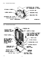
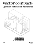
With the Vector Compact you can achieve multi-directional
supply air discharge from a single unit by rotating the blower to the desired location. It is ideal for tight installations
as 130° of rotation are available with which to position the
blower. Its advanced design allows the blower to be easily
removed for rotating or servicing by removing the two
mounting ring screws and the screws attaching the blower
to the drain pan. Rotate the blower to allow the most direct
flow of air to the supply air grille. Reinstall the mounting
screws. Plug any unused screw holes in the blower to
prevent air loss.
• Electrical tape
• Threaded seal tape
• Beding compound to seal thru hull fittings
• Hardware to secure unit, pump, strainer, grilles & control panel
Condensate Drains
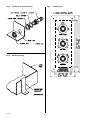
The condensate drain pan is 2” high with up to four drain
locations. During conditions of high humidity, condensate
may be produced at a rate of approximately 1/2 gallon per
hour. With this in mind, it is important to route condensate
drains downward to a sump pump. It is not recommended
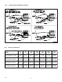
to route condensate drains to the bilge. After the condensate drain installation is complete, test the installation by
pouring a quart of water into the pan and checking for
good flow. See Figure 4.
Mounting Brackets
The a/c unit is supplied with a base pan that also serves
as a condensate pan. Mounting clip brackets are provided
to secure the base pan onto a flat, horizontal surface. See
Figure 5.
Supply & Return Air Grilles
and Transition Boxes
For installation of the condensate drain:
Install the supply air grille as high as possible in a location that will provide uniform air distribution throughout the
cabin, grille louvers should be directed upward. The return
air grille should be installed as low and close to the a/c
unit as possible to insure direct uninterrupted airflow to the
evaporator. The return air grille should have a minimum
four inches (4”) of clearance in front of it, free from any furniture or other obstructions. In no instance should a supply
air discharge be directed towards a return air grille, as this
will cause the system to short cycle. Allow for adequate
clearance behind the supply air grille(s) for the transition
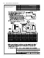
box and ducting connection. The table in Figure 8 shows
minimum grille sizes. See the MAINTENANCE section of
this manual for return air filter cleaning instructions.
1. Remove the aft facing watertight plug from the base pan
of the a/c unit (see note).
2. Slip the solid washer and the liquid-seal washer onto the
PVC fitting in that order.
3. Connect the fitting through the exposed hole in the base
pan with the locking nut.
4. Securely tighten with two (2) wrenches to provide a
proper seal.
5. Attach a 5/8” I.D. reinforced hose to the hose barb and
secure with stainless steel hose clamps.
6. Install the condensate drain hose downhill from the unit
and aft to a sump.
Ducting
7. Two drain fittings may be used and the hoses teed
together provided there is a minimum 2” drop form the
bottom of the base pan to the tee connection.
Good airflow is critical for the performance of the
entire system. It is highly dependent on the quality
of the ducting installation. The ducting should be run
as straight, smooth and taut as possible minimizing the
number of 90° bends (two tight 90° bends can reduce
airflow by 25%). The table in Figure 8 shows minimum duct
diameters and their corresponding supply and return air
grille minimum area in square inches. If a transition box is
used, the total area of supply air ducts going out of the box
should at least equal the area of the supply duct feeding
Note: The reason to use the “aft facing” drain location is so
that water will tend to drain out of the pan when the vessel
is under way. However, the boat owner should inspect the
pan when the vessel is at rest. If water is collecting in the
pan along an edge other than “aft facing”, then the drain on
that edge should also be utilized. This will help to prevent
L-2254 Installation
6
❖ English