1
Model RXT-300
SmartWireless™ Transceiver
Operator’s Installation and Instruction Manual
DETCON, Inc.
4055 Technology Forest, Suite 100
The Woodlands, Texas 77381
Ph.281.367.4100 / Fax 281.298.2868
www.detcon.com
January 03, 2012 • Document # 3481 • Revision 2.0
RXT-300 SmartWireless™
Page intentionally blank
Shipping Address: 4055 Technology Forest, Suite 100, The Woodlands Texas 77381
Mailing Address: P.O. Box 8067, The Woodlands Texas 77387-8067
Phone: 888.367.4286, 281.367.4100 • Fax: 281.292.2860 • www.detcon.com • [email protected]
RXT-300 Wireless IM
ii
RXT-300 SmartWireless™
Table of Contents
1.0
1.1
1.2
1.3
1.4
1.5
1.6
2.0
Introduction.............................................................................................................................................. 1
Description ........................................................................................................................................... 1
RXT-300 Wireless Radio ..................................................................................................................... 3
Model 100 Terminal Board (Optional)................................................................................................. 4
Smart Battery Pack (Optional) ............................................................................................................. 4
Quad Battery Charger (Optional) ......................................................................................................... 5
Solar Panel (Optional) .......................................................................................................................... 6
Installation................................................................................................................................................ 7
2.1
Guidelines for Safe Use........................................................................................................................ 7
2.2
Mounting .............................................................................................................................................. 8
2.2.1
Remote Mounting ......................................................................................................................... 9
2.3
Wiring Connections / Functions......................................................................................................... 12
2.3.1
VDC Power & VDC Return........................................................................................................ 12
2.3.2
Modbus™ A & B ........................................................................................................................ 13
2.3.3
Alarm 1-4.................................................................................................................................... 13
2.3.4
4-20mA A & B ............................................................................................................................ 14
2.3.5
Serial Clock & Serial Data Line ................................................................................................ 15
2.3.6
Programming Data, Clock & Reset............................................................................................ 15
3.0
System Operation................................................................................................................................... 15
3.1
Station Configuration ......................................................................................................................... 16
3.2
HMI Station Operation ....................................................................................................................... 16
3.3
Sensor Station Operation.................................................................................................................... 16
3.4
Alarm Station Operation .................................................................................................................... 17
3.4.1
Alarm Output Properties ............................................................................................................ 18
3.4.2
Alarm Zones ............................................................................................................................... 18
3.4.3
Alarm Setup Summary ................................................................................................................ 19
3.5
Network Sleep .................................................................................................................................... 19
3.6
Network Control................................................................................................................................. 19
3.6.1
Alarm Reset and Alarm Silence.................................................................................................. 19
3.6.2
Alarm Inhibit .............................................................................................................................. 20
3.6.3
Alarm Test .................................................................................................................................. 20
3.6.4
RF Silence................................................................................................................................... 20
4.0
System Configuration ............................................................................................................................ 21
4.1
Overview ............................................................................................................................................ 21
4.2
Building a System .............................................................................................................................. 21
4.2.1
System Build Info........................................................................................................................ 21
4.2.2
Alarm Zone Build Info ................................................................................................................ 22
4.2.3
RXT-300 Build Info .................................................................................................................... 23
4.2.4
Device (Sensor) Build Info ......................................................................................................... 23
4.3
System Parameters Detailed ............................................................................................................... 24
4.3.1
Network Parameters................................................................................................................... 24
4.3.2
Zones .......................................................................................................................................... 25
4.4
RXT-300 Parameters Detailed ........................................................................................................... 25
4.4.1
RXT-300 Main Settings .............................................................................................................. 25
4.5
Device Parameters Detailed ............................................................................................................... 26
RXT-300 Wireless IM
iii
RXT-300 SmartWireless™
5.0
Modbus Operation................................................................................................................................. 27
5.1
Modbus Addressing – Special Cases.................................................................................................. 28
5.1.1
Address Translation.................................................................................................................... 28
5.1.2
Accessing RXT-300 4-20mA Sensors.......................................................................................... 28
5.2
General Modbus™ Description.......................................................................................................... 28
5.2.1
Modbus™ Exceptions................................................................................................................. 29
5.3
Modbus™ Register Map & Description............................................................................................. 29
5.3.1
Register – Detcon Type .............................................................................................................. 30
5.3.2
Register – Alarm Outputs ........................................................................................................... 30
5.3.3
Register – 4-20mA Reading........................................................................................................ 31
5.3.4
Register – Battery Info................................................................................................................ 31
5.3.5
Register – uC Firmware Version................................................................................................ 31
5.3.6
Register – Radio Firmware Version and Build .......................................................................... 31
5.3.7
Register – Radio Software Version............................................................................................. 32
5.3.8
Register – Control ...................................................................................................................... 32
5.3.9
Register – Status ......................................................................................................................... 32
5.3.10 Register – Timestamp ................................................................................................................. 32
6.0
Troubleshooting Guide.......................................................................................................................... 33
7.0
Warranty ................................................................................................................................................ 33
8.0
Specifications.......................................................................................................................................... 34
8.1
8.2
Spare Parts.......................................................................................................................................... 35
Revision Log ...................................................................................................................................... 36
Table of Figures
Figure 1 System Example utilizing the RXT-300 ............................................................................................. 2
Figure 2 SmartWireless™ Typical Product Family .......................................................................................... 2
Figure 3 Mesh Network Topology ................................................................................................................... 3
Figure 4 Model 100 Terminal Board................................................................................................................. 4
Figure 5 Smart Battery Pack ............................................................................................................................. 5
Figure 6 Quad Battery Charger ......................................................................................................................... 5
Figure 7 Solar Panel .......................................................................................................................................... 6
Figure 8 RXT-300 Approval Label .................................................................................................................. 7
Figure 9 RXT-300 Wireless Transceiver w/Battery Assembly and Mounting Dimensions ............................ 8
Figure 10 RXT-300 Wireless Transceiver Remote Mounting ......................................................................... 9
Figure 11 Wiring Diagram for Remote RXT-300 Transceiver Mounting ....................................................... 10
Figure 12 Internal Alarm Output Circuit.......................................................................................................... 14
Figure 13 DC/Battery Alarm Board ................................................................................................................. 14
Figure 14 Up to two Sensors using two 4-20mA Interfaces............................................................................. 15
Figure 15 Basic C1D2 Wireless Alarm Stations .............................................................................................. 18
Figure 16 RF Channel Comparisons between 802.15.4 and 802.11 ................................................................ 22
Figure 17 Modbus™ Frame Format................................................................................................................. 28
Figure 18 Analog/Serial Sensor or RTU to RXT-300...................................................................................... 37
Figure 19 700 Serial Sensor to RXT-300 ......................................................................................................... 37
Figure 20 Serial Sensor to RXT-300 ................................................................................................................ 38
Figure 21 HMI Panel to RXT-300.................................................................................................................... 38
Figure 22 Two Analog Sensors to RXT-300.................................................................................................... 39
Figure 23 2 Analog Sensors to RXT-300 ......................................................................................................... 39
Figure 24 Four Serial Sensors to RXT-300...................................................................................................... 40
Figure 25 Four Serial Sensors to RXT-300...................................................................................................... 41
RXT-300 Wireless IM
iv
RXT-300 SmartWireless™
List of Tables
Table 1 Extension Cable Wire Identification .................................................................................................... 11
Table 2 RXT-300 Transceiver Wire Identification ........................................................................................... 12
Table 3 Wire Gauge vs. Distance ...................................................................................................................... 13
Table 4 Exception Codes................................................................................................................................... 29
Table 5 RXT-300 Register Map ........................................................................................................................ 30
RXT-300 Wireless IM
v
RXT-300 SmartWireless™
Page intentionally blank
Shipping Address: 4055 Technology Forest, Suite 100, The Woodlands Texas 77381
Mailing Address: P.O. Box 8067, The Woodlands Texas 77387-8067
Phone: 888.367.4286, 281.367.4100 • Fax: 281.292.2860 • www.detcon.com • [email protected]
RXT-300 Wireless IM
vi
RXT-300 SmartWireless™
1.0 Introduction
1.1 Description
The RXT-300 SmartWireless™ Transceiver is the foundation for the Detcon family of wireless products.
Each RXT-300 comes with an internal multi-channel controller function that allows for monitoring and
generating alarms in an industrial detection system. Communication between RXT-300s occurs wirelessly
using the internal IEEE 801.15.4 radio. Detcon products using the RXT-300 have been also designed for low
power operation and can be powered using Detcon battery packs and solar panels. Since these units are both
wireless and can be set up to be battery/solar powered, they become very mobile and can be deployed without
installing a costly wiring infrastructure.
Several features have been incorporated in the RXT-300 design allowing the customer to create a robust
wireless gas detection and alarm system.
•
•
•
•
•
•
•
•
•
•
•
•
•
•
•
Internal multi-channel controller – No external controller required to manage system
Wireless Mesh Network – multiple paths of communication between RXT-300s
Any RXT-300 can become master of the wireless network – no single point of failure
Each RXT-300 processes local and network data and determines alarms independently
Alarm Zones allows grouping of RXT-300s/Sensors to specific Alarm Stations
Up to four sensors per RXT-300
Up to two 4-20mA sensors per RXT-300
Up to four fully configurable Alarm Outputs per RXT-300
Can add multiple HMI (Human Machine Interface) Panels for monitoring of network
Low power design for extended operation on battery
Wireless Network sleep available to further reduce power consumption
Battery Life monitoring for one SmartWireless™ Battery Pack
Maximum 32 RXT-300s and/or 32 Sensors per Network
Operates with a wide DC input range from 7-30VDC
Class 1 Div 1; Groups D, C
Detection systems normally consist of a controller, sensors and alarm stations with each placed at different
locations based upon the needs of the customer. These would then be wired together to complete the system
installation and provide communication throughout the system. When using the RXT-300 SmartWireless™
Transceiver, the RXT-300 would be installed at each location and communication between devices would
occur wirelessly. Figure 1 shows an example of a possible system configuration.
RXT-300 Wireless IM
Rev. 2.0
Page 1 of 41
RXT-300 SmartWireless™
Figure 1 System Example utilizing the RXT-300
The RXT-300 is usually built up as part of an assembly to satisfy one of three different applications, the HMI
(Human Machine Interface) Station for visual status of the network, the Sensor Station that has one or more
sensors attached and the Alarm Station for system alarm indication. These three basic assemblies are then
duplicated and located as needed by the customer. Figure 2 shows the Detcon versions of the typical
SmartWireless™ assemblies. Each device within the SmartWireless™ assemblies has been chosen or
designed for low power operation and can therefore be powered using the Detcon Smart Battery pack and
supplemented with a solar panel.
HMI Station
Sensor Station
Alarm Station
Figure 2 SmartWireless™ Typical Product Family
RXT-300 Wireless IM
Rev. 2.0
Page 2 of 41
RXT-300 SmartWireless™
The RXT-300 has been designed with multiple interfaces to support these three applications. There is a single
RS-485 interface that utilizes the Modbus™ RTU protocol and can be set up as a Modbus™ Master or
Modbus™ Slave. As a Modbus™ Master the interface will support up to four Modbus™ sensors and will poll
the sensors and process alarms for those sensors. As a Modbus™ Slave it supports a single HMI (Human
Machine Interface) Panel or Modbus™ controller to display status of the sensors and RXT-300s as well as
providing control over the network such as resetting of alarms.
There are two 4-20mA inputs that can be used for monitoring 2-Wire or 3-Wire 4-20mA devices. There are
four Alarm outputs that can be configured to be Energized or De-Energized, Latching or Non-Latching and
Silence-able or Non-Silence-able. The RXT-300 can also monitor a single Detcon Smart Battery pack for
remaining battery life allowing the user to replace the battery in a timely manner.
1.2 RXT-300 Wireless Radio
The RXT-300 transceivers utilize radios based upon the IEEE 802.15.4 standard that operate at 2.4 GHz using
DSSS encoding for robustness. DSSS was initially used by the military to resist jamming but later was widely
adopted for wireless implementations since it was robust in noisy environments. DSSS transmits data across a
wider frequency range than the actual frequency range required for the information. This operation minimizes
cross talk and interference from other transceivers and is less susceptible to noise from other sources.
The IEEE 802.15.4 defines 16 separate RF Channels that can be used in the 2.4 GHz range. The default
channel is 1 but can be change if there is RF interference or if there is an existing network using that channel.
Transceivers will only respond to other transceivers with the same RF Channel.
NOTE: If there are multiple Modbus™ networks in the same vicinity each system must reside
on a different RF Channel to keep data from one appearing on the other.
The 802.15.4 standard also implements a mesh network allowing any RXT-300 transceiver to relay or repeat
data between adjacent neighbors. This makes the network very robust and provides the following immediate
benefits:
•
•
•
•
•
Allows re-routing of data in case of loss of a transceiver
Allows re-routing around wireless obstacles
Longer distances between transceivers because data can “hop” from one transceiver to the next
Included in sensor, controller and alarm station transceivers
RXT-300 transceivers can be deployed with less concern about physical location
Figure 3 Mesh Network Topology
RXT-300 Wireless IM
Rev. 2.0
Page 3 of 41
RXT-300 SmartWireless™
1.3 Model 100 Terminal Board (Optional)
The RXT-300 wireless transceiver can be ordered with an optional Model 100 Terminal Board mounted in a
condulet/J-Box (See Figure 4). The terminal board includes connector plugs for the following:
6-Pin Phoenix Connector
5-Pin Phoenix Connector
6-Pin Connector
3-Pin Phoenix Connector
3-Pin Phoenix Connector
8-Pin Beau Connector
3-Pin Phoenix Connector
3-Pin Phoenix Connector
RXT-300 Wireless Transceiver
Slave Device/HMI/Master Controller
RXT-300 Programming Port (Detcon Factory use only)
Model 100 Loop Powered LED display
7-30VDC External power source or 24VDC Solar Panel
12VDC Battery Power (Use only Detcon’s Smart Battery Pack)
Spare Modbus™ Connection
RXT Programming Interface to Wireless Transceiver
r
e
v
i
e
c
s
n
a
r
T
0
0
3
T
X
R
1
- SJ
E
RS
IE
WL
R
K
B
W
U
B
/R
WB
/K
WB
8
J
ge
oc
r
a
Pf
r
Tt
e
Xn
RI
6
J
5
J
C
nC
DI
D
lr
a
eV
nw
0
r
3
e
ot
P7
x
E
1
P
T
A
S
-
+
dy
e
rl
a
e
p
ws
oi
PD
pD
oE
o
LL
s
u
B
d
o
M
e
r
a
p
S
4
J
7
J
︵
V
/
W
/N
WG
/U
WB
3
J
k
c
a
P
y
r
e
t
t
a
B
t
r
a
m
S
B
S
A
W
B
W
1 2 3 4 5 6 7
2
P
T
3
2
1
+
-
A
m
y
tl
r
on
PO
ge
s
o
U
r
Pn
To
Xc
t
Re
D
︶
J1:
J2:
J3:
J4:
J5:
J6:
J7:
J8:
N
G
U
B
W
K
B
R
2
J
/r
I
e
Ml
l
Ho
/t
r
e
cn
i
vo
eC
r
De
et
vs
aa
l
M
S
/
R
OI
SM
NH
E
S
Figure 4 Model 100 Terminal Board
1.4 Smart Battery Pack (Optional)
The RXT-300 transceiver can also be powered by an optional battery pack that enables it to be remotely
mounted without the need for any cables because of its wireless operation. The available battery pack is
Detcon’s plug-in Smart Battery Pack which provides an output of 12VDC (See Figure 5). If installed, the
RXT-300 transceiver will detect the battery and will continuously query the battery pack for remaining battery
life. The battery pack consists of rechargeable Lithium-Ion batteries and is equipped with integrated safety
electronics that include fuel gauge, voltage, current and temperature monitoring circuits. This “smart”
circuitry continuously monitors the battery’s condition and reports critical status information to the wireless
transceiver via the Modbus™ registers. The battery pack is designed to plug onto an 8-pin Beau connector on
the Model 100 Terminal Board and should not be exposed to outside elements without being housed and
protected. Only Detcon products specifically designed to utilize these battery packs should be used.
Operating periods before recharge will vary based on devices attached along with the transceiver and the usage
of those devices, but can be as long as 2-3 months and battery life can be up to 5 years before battery pack
replacement is required. Improper use of the battery pack may be hazardous to personnel or the environment
and will void the warranty.
RXT-300 Wireless IM
Rev. 2.0
Page 4 of 41
RXT-300 SmartWireless™
Figure 5 Smart Battery Pack
NOTE: The RXT-300 wireless transceiver can also be powered by a customer provided
external DC power source. Refer to section 0 for more details.
1.5 Quad Battery Charger (Optional)
Detcon’s Smart Battery Pack can be charged as needed using Detcon’s optional Quad Battery Charger which
can charge up to four battery packs at one time. The Quad Battery Charger comes with a plug-in AC/DC
adapter that plugs into a standard 120VAC outlet for power. The DC end of the adapter plugs into the DC
power jack of the charger providing 24VDC. The Quad Battery Charger has four charging ports, each with 8pin Beau connectors for battery pack connection. The ports and connectors are keyed to prevent incorrect
positioning and connection. Each port has its own “FAULT” LED indicator and “CHARGE” LED indicator
and will display either a red light or green light depending on the status of each battery being charged.
Charging times will vary depending on the charge state of each battery pack, but a full charge of a depleted
battery pack can take up to 24 hours.
Figure 6 Quad Battery Charger
RXT-300 Wireless IM
Rev. 2.0
Page 5 of 41
RXT-300 SmartWireless™
When first powered on and with no battery packs connected to the charger, all the LED indicators on the Quad
Charger should be green. When a battery pack is seated into a charging port, the “CHARGE” LED will
change from green to red indicating the battery pack is not sufficiently charged. Once fully charged, the LED
will change from red to green and the battery pack is ready to be used.
The “Fault” LED should remain green indicating that there are no problems with the battery pack or charging
port. If the “Fault” LED turns red with the battery pack connected, then there is a problem or issue with the
battery pack and it should be immediately removed and not be used. If the “Fault” LED turns red without a
battery pack connected to the charge port, then there is a problem or issue with the port and that port should no
longer be used.
Battery packs can remain connected to the charger even after a full charge indication (Green “Charge” LED) is
shown due to the protection circuitry of the battery pack which prevents any overcharging issues.
1.6 Solar Panel (Optional)
Detcon also offers an optional solar panel to be used in conjunction with the Smart Battery Pack. It provides
24VDC output and connects to the J5 connector of the Model 100 Terminal Board. This option enables
continuous operation of the wireless transceiver and charging of the battery pack eliminating the need for
external recharging. It is an ideal choice for virtually any area with sufficient daily average sunlight. Since
the solar panel is considered and external power supply, a special conduit installation will be required.
If the optional solar panel is installed, consideration should be given to position the panel where the most
sunlight is available. The solar panel can be mounted remotely to allow for maximum sunlight exposure. If
necessary, a sunshade can be used for the wireless transceiver assembly to help reduce its operating
temperature.
Figure 7 Solar Panel
RXT-300 Wireless IM
Rev. 2.0
Page 6 of 41
RXT-300 SmartWireless™
2.0 Installation
2.1 Guidelines for Safe Use
1. Install unit only in areas with classifications matching with those described on the approval label. Follow
all warnings listed on the label.
Figure 8 RXT-300 Approval Label
2. Do not use in areas containing air saturation levels of Acetic Acid, Acetone, Ammonium Hydroxide, Fuel
C, Diethyl Ether, Ethyl Acetate, Ethylene Dichloride, Furfural, N-Hexane, MEK, Methanol, 2Nitropropane, or Toluene.
3. Ensure that the transceiver is properly threaded into a suitable explosion-proof rated junction box with a
female ¾” NPT threaded connection. The sensor should be threaded up at least 5 full turns until tight.
Avoid use of Teflon Tape, or any type of non-conductive pipe thread coating on the NPT threaded
connection.
4. A good ground connection should be verified between the sensor’s metal enclosure and the junction box.
If a good ground connection is not made, the sensor can be grounded to the junction box using the sensor’s
external ground lug. Also verify a good ground connection between the junction box and earth ground.
5. Proper precautions should be taken during installation and maintenance to avoid the build-up of static
charge on the plastic weather-guard of the transceiver.
6. Do not substitute components that are not authorized by the scope of the safety approval. This may impair
the intrinsic safety rating.
7. Do not operate the unit outside of the stated operating temperature limits.
8. Do not operate the unit outside the stated operating limits for voltage supply.
9. The sensor power supply common (black wire) must be referenced to the metal enclosure body (ground)
during installation.
10. These units are designed to meet EN60079-0, EN60079-1, EN60079-11, UL913 7th Ed., and CSA C22.2
No.157-92.
11. These units are designed have a maximum safe location voltage of Um=30V.
12. These units pass dielectric strength of 500VRMS between circuit and enclosure for a minimum of 1
minute at a maximum test current of 5mA.
RXT-300 Wireless IM
Rev. 2.0
Page 7 of 41
RXT-300 SmartWireless™
2.2 Mounting
The RXT-300 wireless transceiver should be vertically oriented and mounted to an explosion-proof enclosure
or junction box. The J-Box contains the optional Model 100 Terminal Board. If a battery pack is used,
Detcon’s custom J-Box is needed to accommodate both the terminal board and the battery pack plus a T-Outlet
box with a drain is required (See Figure 9). The RXT-300 wireless transceiver assembly is typically mounted
on a wall or pole.
Obstacles between RXT transceivers can impact RF line-of-sight and may result in communication problems.
Each transceiver should be in view of at least one other transceiver. In some cases, it may be necessary to
extend and elevate the RXT transceiver away from the J-Box/device assembly. Refer to section 2.2.1 for such
remote mounting applications
Detcon offers an optional mounting plate that can be used for mounting the wireless transceiver assembly on a
wall or pole. If ordered with this option, secure the wireless transceiver assembly to the mounting plate using
two of the four 3/8” diameter holes located on the top face of the mounting plate (If not already done so from
the factory). The whole assembly can now be mounted on a secure wall using the four 7/16” diameter holes
located on the base of the mounting plate (See Figure 9). The assembly can also be mounted to a pole with
two U-Bolts secured through the 7/16” holes on the base.
NOTE: If wall mounting without the mounting plate, make sure to use at least 0.5” spacers
underneath the J-Box’s 1/4” mounting holes to move the wireless transceiver assembly away
from the wall and allow clearance to the transceiver.
10" Typ.
r
e
v
i
e
c
s
n
a
r
T
s
s
e
l
e
r
i
W
s
e
i
r
e
S
T
X
R
︵
︶
e
r
ec
a
hf
t
r
ou
r
os
g
n
i
t
l
l
an
u
Wo
m
e
t
a
l
P
gl
na
i
t
n
n
o
ui
ot
p
MO
n
o
c
t
e
D
︵
︶
71
g
n4
i
t
x
n
s
ue
ol
mo
"6h
3.5"
s
t
r
o
P
T
P
N
"
34
15.7"
6.1"
5.5"
7.135"
g
n4
i
x
t
n
s
ue
oo
l
mh
"
38
x
o
n
Bi
a
tr
e
l
D
t
/
u
Ow
T
5" 8"
g
n2
i
x
t
n
s
ue
oo
l
mh
"
14
7"
x
o
Bn
o
J
i
t
mp
uO
ny
i
r
me
ut
t
l
a
A
B
mr
oo
t
F
s
u
C
8-32 tapped
ground point
︵
︶
2.5"
Figure 9 RXT-300 Wireless Transceiver w/Battery Assembly and Mounting Dimensions
RXT-300 Wireless IM
Rev. 2.0
Page 8 of 41
RXT-300 SmartWireless™
2.2.1
Remote Mounting
The RXT-320 wireless transceiver is normally connected directly to the J-Box containing the battery/terminal
board assembly. In situations where RF line-of-sight is diminished by obstructions, it may be necessary to
remotely mount the wireless transceiver away from this J-Box. Remote separation distances of up to 15 feet
are possible with the recommended cable. Such an installation will require an additional J-Box which
connects to the separated transceiver and houses Detcon’s 8-position terminal board with Ground board plus
additional hardware (See Figure 10).
Remote RXT-300 Wireless Transceiver
Remote J-Box w/
8-Position
Terminal Board
Remote 34" NPT
T-Outlet Box w/Drain
Power, Modbus & I²C
Extension Cable to/from
Remote RXT Transceiver
Up to 15' Length
3
4"
NPT Cord Connectors
(Cable Glands) Required
J-Box w/
Model 100
Terminal Board
R
K
B
W
U
B
/R
WB
/K
WB
og e
Pr ac
T rf
X te
R In
J6
J8
5
J
J3
A
S
-
+
7
J
J4
ed y
er la
w
o sp
P Di
D
op E
Lo L
us
B
od
M
re
pa
S
︵
/V
W
/N
WG
/U
WB
P2
T
ck
Pa
ry
te
at
B
t
ar
m
S
B
S
A
W
B
W
1 2 34 5 67
+
-
A
m
3
2
1
y
t
or nl
PO
se
og U
Pr
T on
Xc
et
RD
︶
C
D C
l In D
er V
na w
er 30
xt Po 7E
1
P
T
er
v
ei
sc
an
Tr
0
32
TX
R
NPT T-Outlet
Box w/Drain
J1
E- S
S
IR E
WL
3
4"
N
G
U
B
W
K
B
R
J2
R/
O
S MI
NH
E
S
r/
or
e/ le
ol it
ic tr
on
ev on M
DC e
ve r ot
a te m
e
Sl as R
M
Figure 10 RXT-300 Wireless Transceiver Remote Mounting
A custom extension cable needs to be built per Figure 11 to interface the remote transceiver to the Model 100
Terminal Board. The recommended cable for remote transceiver separation is Belden 1421A (24AWG
shielded twisted pair, 4 pairs w/drain wire).
NOTE: It is highly recommended to install the extension cable inside rigid metal conduit to
eliminate potential EMI and RFI interference and to maintain a Class I Division I rating.
NOTE: Color coding of the cable will no longer match the color coding on the Model 100
Terminal Board for the J1 connector.
RXT-300 Wireless IM
Rev. 2.0
Page 9 of 41
RXT-300 SmartWireless™
NOTE: Programming of RXT transceiver from the Model 100 Terminal Board will be
disabled.
Blk (Gnd -)
Wht/Brn (Serial Data)
Blu (Modbus A)
RXT-300
Transceiver Wiring
Wht (Modbus B)
Red (Pwr +)
Wht/Vio (Prog Reset)
Wht/Grn (Prog Data)
Wht/Blu (Prog Clock)
Wht/Blk (Serial Clock)
4-Pin Phoenix
Connectors
8-Position Terminal
Board with Ground
4-Pin Phoenix
Connectors
Grn/Wht (Gnd -)
Wht/Orn (Gnd -)
Brn/Wht (Gnd -)
Drain Wire
Extension Cable
(Belden 1421A)
Wht/Brn (Serial Data)
Blu/Wht (Modbus A)
Wht/Blu (Modbus B)
Orn/Wht (Pwr +)
Wht/Grn (Serial Clock)
6-Pin Phoenix
Connector
r
e
v
i
e
c
s
n
a
r
T
0
0
3
T
X
R
1
- SJ
E
RS
IE
WL
R
K
B
W
U
B
/R
WB
/K
WB
8
J
ge
o
rc
a
P
f
r
Tt
e
Xn
RI
6
J
1
P
T
5
J
A
S
-
+
d
ey
r
l
ea
wp
s
oi
PD
pD
o
oE
LL
4
J
7
J
︶
︵
V
/
W
/N
WG
/U
WB
3
J
s
u
B
d
o
M
e
r
a
p
S
y
l
rt n
o
PO
e
gs
oU
r
Pn
o
Tc
Xt
Re
D
k
c
a
P
y
r
e
tt
a
B
rt
a
m
S
B
S
A
W
B
W
1 2 3 4 5 6 7
2
P
T
3
2
1
C
nC +
DI
D
lr
a
eV n
rw0
3
e
ot
P7
A
x
E
m
Model 100
Terminal Board
N
G
U
B
W
K
B
R
2
J
/
R
OI
SM
NH
E
S
I/ r
Me
ll
Ho
/ tr
e
n
c
io
v
eC
r
De
et
s
va
aM
l
S
Figure 11 Wiring Diagram for Remote RXT-300 Transceiver Mounting
Remote Mounting Steps
1. Remove the J-Box cover of the RXT-300 wireless transceiver assembly.
2. If the wireless transceiver assembly has the Smart Battery Pack, unplug the battery pack from the
terminal board by pulling the battery pack out of the junction box.
3. Identify the J1 6-pin Phoenix connector and the J8 3-pin Phoenix connector on the Model 100 Terminal
Board and disconnect from the board. Remove all transceiver wire connections from the connectors.
Reconnect the 3-pin connector to its corresponding place and save the 6-pin connector for step 13.
4. Use a wrench at the bottom section of the RXT transceiver and unthread the RXT until it can be removed.
5. Feed the RXT transceiver wires through the ¾” NPT hole of the remote T-Outlet box connected to the
remote J-Box and thread the transceiver into the remote T-Outlet box until tight.
6. Remove all 6 of the 4-pin Phoenix connectors from the 8-position terminal board with Ground in the
remote J-Box and connect the RXT transceiver wires to 3 of the Phoenix connectors per the wiring
RXT-300 Wireless IM
Rev. 2.0
Page 10 of 41
RXT-300 SmartWireless™
diagram in Figure 11. Reference Table 2 RXT-300 Transceiver Wire Identification for color code
identification.
NOTE: Wires that are not used should be individually capped off and secured out of the way
in the T-Outlet box so that they are not exposed to any active components, power, or ground.
7. Reconnect these 3 Phoenix connectors to their corresponding places back on the 8-position terminal
board with Ground.
8. Measure out the cable to be used for the extension cable to be no more than 15 feet long. Feed one end of
the cable through a ¾” NPT cord connector (cable gland) and then into the ¾” NPT hole located on the
bottom of the remote J-Box.
9. Connect the cable wires of the extension cable to the remaining three 4-pin Phoenix connectors from step
6 per the wiring diagram in Figure 11. Reference Table 1 Extension Cable Wire Identification for
color code identification.
10. Reconnect these 3 remaining Phoenix connectors to their corresponding places back on the 8-position
terminal board with Ground and thread the ¾” NPT cord connector to the bottom of the remote J-Box.
11. Install the J-Box cover of the remote J-Box.
12. Feed the other end of the cable through another ¾” NPT cord connector and then into the ¾” NPT hole of
the T-Outlet box connected to the J-Box housing the Model 100 Terminal Board.
13. Connect the cable wires to the 6-pin Phoenix connector from step 3 per the wiring diagram in Figure 11.
Reference Table 1 Extension Cable Wire Identification for color code identification.
14. Reconnect the 6-pin Phoenix connector back to J1 of the Model 100 Terminal Board and thread the ¾”
NPT cord connector to the T-Outlet box.
NOTE: Color coding of the cable will no longer match the color coding on the Model 100
Terminal Board for the J1 connector.
NOTE: Programming of RXT transceiver from the Model 100 Terminal Board will be
disabled.
15. Plug battery pack back in place and reinstall the J-Box cover from step 1.
Table 1 Extension Cable Wire Identification
Function
VDC Power (+)
VDC Return (-)
Modbus A (+)
Modbus B (-)
Serial Clock (SCL)
Serial Data Line (SDA)
Common Ground
Common Ground
Drain Wire
RXT-300 Wireless IM
Color Reference
Orange/White
Green/White
Blue/White
White/Blue
White/Green
White/Brown
White/Orange
Brown/White
Bare (No Color)
Rev. 2.0
Page 11 of 41
RXT-300 SmartWireless™
2.3 Wiring Connections / Functions
Depending on use and function, the RXT-300 wireless transceiver can be wired in different ways to different
devices. It is important to insure that the wiring is correct for the device to operate properly. Wire
identification for the transceiver can be found in Table 2 RXT-300 Transceiver Wire Identification.
Table 2 RXT-300 Transceiver Wire Identification
Function
VDC Power (+)
VDC Return (-)
Modbus™ A (+)
Modbus™ B (-)
Alarm 0
Alarm 1
Alarm 2
Alarm 3
4-20mA A
4-20mA B
Serial Clock (SCL)
Serial Data Line Data (SDA)
Programming Data
Programming Clock
Programming Reset
Color Reference
Red
Black
Blue
White
Brown
Orange
Violet
Gray
Green
Yellow
White/Black
White/Brown
White/Green
White/Blue
White/Violet
NOTE: Reference Figure 18 through Figure 25 at the end of this manual for multiple wiring
examples.
2.3.1
VDC Power & VDC Return
All RXT-300 wireless transceivers need to have DC power applied to the transceiver’s red (VDC power) and
black (VDC return) wires. The power requirements for the transceiver are such that the DC voltage input
range is 7 to 30 volts. This power will normally be supplied by the device the transceiver is connected to, but
can come from alternate DC sources such as the optional Smart Battery Pack, solar panel or external customer
supplied DC source.
If an external power source is installed, the RXT-300 wireless transceiver requires two conductor connections
for the power supply. External DC power can be customer provided with an output voltage range between 7 to
30VDC or by Detcon’s optional 24VDC solar charging panel. Both of these alternatives will provide
continuous operation of the assembly and can be installed in conjunction with the optional battery pack,
providing a constant power source. The external power supply will also maintain the battery pack fully
charged with no overcharging issues to be concerned with due to the battery pack’s “smart” circuitry. In this
configuration, external charging of the battery pack will not be necessary. In the event the external power
fails, the battery pack will continue to power the wireless transceiver assembly until external power is restored
or the battery is discharged.
If the Model 100 Terminal Board option is not used, power to the transceiver should be directly applied to its
red and black wires accordingly. If the terminal board is used, wiring designations for power are ‘+’ and ‘-’
(External DC Power In) on the J5 connector of the Model 100 Terminal Board. The maximum wire length
between the transceiver assembly and a 24VDC source is shown in Table 3 Wire Gauge vs. Distance.
RXT-300 Wireless IM
Rev. 2.0
Page 12 of 41
RXT-300 SmartWireless™
Table 3 Wire Gauge vs. Distance
AWG
Wire Dia.
Meters
Feet
22
20
18
16
14
0.723mm
0.812mm
1.024mm
1.291mm
1.628mm
700
1120
1750
2800
4480
2080
3350
5250
8400
13,440
Over-Current
Protection
3A
5A
7A
10A
20A
NOTE: Wiring table is based on stranded tinned copper wire and is designed to serve as a
reference only.
NOTE: The supply of power should be from an isolated source with over-current protection
as stipulated in table. The output voltage range must be between 7-30VDC.
Before applying power, make sure that all wiring is correct. Not all wires from the wireless transceiver are
used in most configurations. Wires that are not used should be individually capped off and secured out of the
way in the T-Outlet that mounts the transceiver to the J-Box/condulet. This prevents exposure to any active
components, power or ground.
2.3.2
Modbus™ A & B
The RXT-300 transceiver features a Modbus™ compatible communication port. The connections are
Modbus™ A (blue wire) and Modbus™ B (white wire) and are polarity dependent. Modbus™
communication is accomplished by two wire half duplex RS-485, 9600 baud, 8 data bits, 1 stop bit, no parity,
through the transceiver’s connection to the Modbus™ device. It is necessary to set a Modbus address for the
RXT-300 unless operating in transparent mode.
2.3.3
Alarm 1-4
Each RXT-300 wireless transceiver provides outputs for up to four alarms (Alarm 1, Alarm 2, Alarm 3 and
Alarm 4) which can drive relays on custom terminal boards provided by Detcon. The outputs are controlled
by the RXT-300 based upon the configuration and current alarm state of the whole network. The outputs are
open drain and rated for up to 300mA at 50V (See Figure 12). They are not intended to drive alarm devices
directly, but rather to drive relay coils (interposing relays) which in turn will drive a higher current output.
When using interposing relays, the customer must protect the RXT-300 Alarm outputs against the voltage
spike that can be over 1000V when the relay is de-energized. This voltage spike will damage the Alarm output
since it is well over the rated maximum voltage of 50V and will cause the output to fail. A transient protection
diode (1N4001 or equivalent) can be placed across the relay coil to mitigate the voltage spike.
NOTE: External relays used with this circuit must not exceed voltage/current requirements
and must have transient protection to minimize the voltage spike when the coil is de-energized.
RXT-300 Wireless IM
Rev. 2.0
Page 13 of 41
RXT-300 SmartWireless™
Interposing Relay
RXT-300
Alarm Output
1N4001
Diode
From RXT-300
Processor Output
Relay
Coil
MOSFET N-CH
50V 300mA
V+
49.9K
Figure 12 Internal Alarm Output Circuit
Detcon alarm terminal boards are available that allow either AC or DC/Battery operation with the relays built
onto the board. These boards provide a complete solution to connecting an RXT-300 to power and providing
high-current relay closures. Figure 13 shows as an example, the DC/Battery Alarm board that take two of the
four RXT-300 Alarm outputs and generates two 24VDC outputs to drive audio and/or visual alarms. Any two
of the four Alarm outputs can be used and will be based on how alarms are configured for the system. This
board is designed to operate off of the 12VDC Detcon Smart Battery pack.
Wiring to/from
Transceiver
External
24VDC
Connections
Wiring to/from
Transceiver
789
Rotary Switch
for Modbus
Address
45 6
CD
AB E
23
F01
Alarm 2
Wiring
Alarm 1
Wiring
Figure 13 DC/Battery Alarm Board
2.3.4
4-20mA A & B
The RXT-300 supports up to two 4-20mA signal inputs (A and B) used for monitoring 4-20mA devices (See
Figure 14). For the primary 4-20mA signal input, use A (green wire). For the secondary 4-20mA signal input,
use B (yellow wire). The input values are continuously read by the RXT-300 and stored in registers accessible
locally through two Modbus™ registers. During system configuration, these registers can be assigned to
sensors and the RXT-300 will then monitor and report on any alarm conditions.
Readings on a 4-20mA input are converted to representative values, for example, 4mA is read as a value of
400 and 20mA is read as a value of 2000. These inputs present a load of 162 ohms to ground so a current of
20mA will develop around 3.4V across the input and ground. This will consume a third less power versus the
250 ohm load used in other implementations. The inputs are protected for voltages up to 30V but the input
RXT-300 Wireless IM
Rev. 2.0
Page 14 of 41
RXT-300 SmartWireless™
reading will reach a maximum of 2048 for currents greater than 20mA. Electrically the 4-20mA interface
supports 2-wire and 3-wire devices.
Figure 14 Up to two Sensors using two 4-20mA Interfaces
NOTE: The 4-20mA inputs do NOT support 4-wire implementations
2.3.5
Serial Clock & Serial Data Line
This is the I2C interface for the transceiver consisting of a serial clock (SCL) and serial data line (SDA). These
are used to monitor the status of the battery pack (if installed).
2.3.6
Programming Data, Clock & Reset
These connections are used to program the RXT-300 transceiver and should be used by Detcon personnel
only.
3.0 System Operation
The gas detection system built with the RXT-300 SmartWireless™ Transceiver operates similar to one using a
single Modbus™ controller that polls (queries) sensors connected to it. Generally upon each poll of a sensor,
data is collected, stored and processed for alarm conditions that are set by the user. If an alarm is detected the
controller activates alarms to alert the user.
In a system using the RXT-300 SmartWireless™ Transceiver, sensors that are attached to a RXT-300 as part
of a Sensor Station are located at different physical locations around the site. Data must be collected from all
of these sensors as if they were wired to a single controller. In addition to sensor data, RXT-300 status such as
battery life and status of the wireless communication between the RXT-300s must be collected. The data for
the whole system is collected by every RXT-300 on the network so that each RXT-300 has a complete picture
of the system. This allows every RXT-300 to operate independently in processing system wide alarm
conditions and allows a HMI Station to display information for the whole system.
To facilitate this, the RXT-300s with sensors attached will poll their own sensors, collect the data and process
the data for alarm conditions and store it locally. It operates essentially like a Modbus™ controller for its own
sensors. To gather the information from across the network, one of the RXT-300s is automatically chosen to
become the Master of all the RXT-300s of the network and will poll each RXT-300 on the network. Upon
RXT-300 Wireless IM
Rev. 2.0
Page 15 of 41
RXT-300 SmartWireless™
each poll a different RXT-300 is queried and will transmit its data stored locally to the rest of the RXT-300s
on the network. This continues until all RXT-300s are polled across the network. As part of the polling
process the Master RXT-300 will also transmit its own data to the network at the appropriate time.
The Master RXT-300 can be any one of the RXT-300s in the network but the “election” process can be guided
by the user when the RXT-300s are configured and set up. If a Master RXT-300 fails this will be detected by
all the other RXT-300s and a new Master RXT-300 will be elected. The network polling will continue after
the election is complete. This alleviates a single point of failure.
3.1 Station Configuration
For the RXT-300s to operate differently based upon the application they must be configured. This is done
with the RXT-300 Wireless Configuration Tool (WCT) and is covered in more detail in Section Error!
Reference source not found.. For purposes of this discussion it is sufficient to state that each RXT-300 in the
system is configured to perform a specific set of tasks. A single configuration file with all this information is
generated by the WCT and loaded wirelessly into the RXT-300s in the system. At power up the RXT-300s
will search through the configuration file and determine its own operation as well as what type of function it
will perform and whether it is a HMI Station, Sensor Station or an Alarm Station
3.2 HMI Station Operation
The RXT-300 RS-485 Modbus™ port can be configured to connect to a Modbus™ Master and allows the
Wireless HMI or a another Modbus™ controller to obtain status of the whole system. Since every RXT-300
maintains a complete status of the system much of this data has been made available for access through
Modbus™ registers on the RXT-300.
NOTE: An HMI Station/Modbus™ controller only monitors the network and does not
perform the actual polling of sensors and processing of alarms. It only provides the user a
visual status of the system and managing of alarms events such as alarm reset/inhibit/silence.
The RXT-300 will allow a direct access to sensor data as if it were directly attached to the controller through
Modbus™. The RXT-300 will perform a lookup based upon the sensor Modbus™ address/registers and
respond with data obtained from the network and stored locally. If the Modbus™ address/registers do not
match a configured sensor it will ignore the request or generate a Modbus™ exception.
If more than just sensor data is desired there are groups of registers that provide access to the status of each
RXT-300, network status and alarm status. There are additional registers that allow for sending commands
across the network. These commands are alarm reset, alarm silence, alarm inhibit, alarm test and RF silence.
Each RXT-300 in the system is assigned a unique Modbus™ address during configuration just like the sensors.
This address is used for all Modbus™ accesses.
The wireless HMI Panel has been designed to take advantage of all aspects RXT-300, both displaying sensor
status, alarms, RXT-300 status and network status. It also performs all control functions available. Another
great advantage is the HMI can read the RXT-300 configuration and automatically configure itself to display
everything about the system.
3.3 Sensor Station Operation
There are two ways sensors or devices can be attached to the RXT-300, using the Modbus™ interface and
using the 4-20mA interface. Sensors are added specific RXT-300s in the configuration along with the
Modbus™ address / registers and the alarm thresholds for each one. If a RXT-300 configured to have sensors
attached to either or both interfaces it will poll these sensors continuously and maintain a local copy of the data
RXT-300 Wireless IM
Rev. 2.0
Page 16 of 41
RXT-300 SmartWireless™
as well as process and store the alarm state of the sensor. The Sensor Station RXT-300 will transmit all its
sensor data to the rest of the network when it is polled by the Master RXT-300. This data is then stored by
every RXT-300 on the network and available for those RXT-300s to perform alarm processing or for user
visibility through a HMI Station.
The Modbus™ interface only supports sensors or a controller not both, so if one or more sensors are attached
it the Modbus™ interface it will not support a controller or HMI. If the sensors only use the 4-20mA inputs
then a Modbus™ controller or HMI can be attached.
The Modbus™ sensors are defined in the system configuration as being attached to a particular RXT-300 and
the Modbus™ address and registers that are to be read. Additionally the register that contains the sensor
concentration is identified and what alarm thresholds are. The RXT-300 will read all registers as configured,
store them locally and then process the concentration for an alarm event. If Detcon sensors are used,
additional fault or calibration info is also processed and made available for display on the HMI Stations.
The two 4-20mA sensor inputs can represent up to two separate sensors if enabled. Their Modbus™ address
becomes the RXT-300 they are attached to. The RXT-300 will actually store the readings for the two inputs
into two separate registers on the RXT-300. A 4-20mA sensor type can be setup that will read this register and
process alarms much like sensors on the Modbus™ interface.
3.4 Alarm Station Operation
Alarms can come from several different sources. These not only include sensors but RXT-300s and network
based alarm events. These alarm events are eventually mapped to just four alarm outputs, Alarm 1-4 on an
RXT-300. All RXT-300s will generate alarms on their alarm outputs but most stations do not have any alarm
devices attached. A list of possible alarm events are shown below:
•
•
•
•
•
•
•
Sensor Threshold Settings, Ascending or Descending
Sensor Communication Errors
Sensor Fault conditions – Detcon sensors types only
Battery Threshold on remaining time
Battery Communication Error (fault)
Network Communication Error – one of more RXT-300s offline
Network Down – no Master RXT-300
Mapping of these alarm events is configurable to any one of the Alarm 1-4 outputs on a device by device basis
but defaults are generally used. Alarms can also be grouped using Zones which is covered later. Each
RXT-300 will process all alarms for itself which will include sensors if any, battery status and network status.
Upon detection of an alarm event the local Alarm outputs will be updated. This information is disseminated
later when that RXT-300 is polled by the Master RXT-300 and at this point all RXT-300s will receive the new
alarm state and update their alarm outputs accordingly.
Detcon Alarm Stations that can operate off of a single Detcon Smart Battery pack will have two alarm devices
attached. Alarm devices were selected to minimize the power consumption and yet maximize the alarm
coverage. Figure 15 shows units designed for installation and use in Hazardous duty, corrosive work
environments rated at Class 1, Division 2, Groups E, F, and G.
RXT-300 Wireless IM
Rev. 2.0
Page 17 of 41
RXT-300 SmartWireless™
AV1-DV2
Strobe Horn Combo
Alarm Station
V2-DV2
Dual Strobe
Alarm Station
A1-DV2
Horn Only
Alarm Station
Figure 15 Basic C1D2 Wireless Alarm Stations
Although not at Alarm station, the HMI Panel has four LEDs that provide a visible indication of the four alarm
outputs. The HMI LEDs will follow the state of the alarm outputs and are labeled ALM 1, ALM 2, ALM 3
and FAULT. Alarm 4 in Detcon detection systems is usually mapped to fault conditions such as
communication errors or sensor faults where Alarm 1-3 are usually mapped to threshold settings for sensors
3.4.1
Alarm Output Properties
Alarm outputs on RXT-300s can be configured with certain properties such as Energized / non-Energized,
Latching / non-Latching and Silence-able / non-Silence-able. These are configured for each RXT-300 and
only affect the Alarm outputs on that RXT-300. Energized / non-Energized determines the active state of the
Alarm output where Energized means the open collector output is grounded when the alarm is active and
non-Energized is the opposite. Latching / non-Latching determines whether the Alarm output is latched. With
Latching selected, if an alarm event ever occurred the Alarm output will be active regardless of the current
state of the alarm. Non-Latching causes the Alarm output to just follow the current state of any alarm
condition. The Silence-able property allows the user to turn off the Alarm output even though there is an
existing alarm. If the alarm goes away and comes back again, silence is removed and the Alarm output will
become active again. The Non-Silence-able setting does not allow the Alarm output to be silenced.
NOTE: At power up or reset, the default for Energize / non-Energize on the RXT-300 is set to
Energized until the configuration is fully loaded. If the RXT-300 is configured for nonEnergize there will be a short period of time at power up or reset the external Alarm will
activate until power-up configuration is complete.
3.4.2
Alarm Zones
RXT-300s can be grouped into alarm Zones to allow Alarm Stations to generate alerts for a group of sensors in
a Zone. There can be up to 16 Zones defined by the user each RXT-300 can be assigned to one or more
Zones. For example if there were two sets of 3 Sensor Stations that were separated by a large distance the user
can define two Zones one for each set of 3 and the user could place an Alarm Station in each Zone. When an
alarm event occurs in Zone 1 only that Alarm Station would activate and the same would be true for Zone 2.
Now if an HMI Station were added it could be placed in both Zone 1 and Zone 2 and any alarm in the system
would show up on the four Alarm LEDs on the HMI. A “global” Alarm Station could also be added and
placed in both Zone 1 and Zone 2 and that Alarm Station would activate for any alarm in the system.
RXT-300 Wireless IM
Rev. 2.0
Page 18 of 41
RXT-300 SmartWireless™
3.4.3
Alarm Setup Summary
In summary, there are alarm events that are generated for multiple conditions around the system. For every
alarm event they can be either ignored or they can be mapped into one of four Alarm Outputs. Alarm Zones
provides additional mapping of these Alarm Outputs to specific groups of RXT-300s. Finally, the Alarm
Outputs on each RXT-300 have properties to configure the way the Alarm Outputs operate. Each of these
settings is part of the configuration that the user creates and stores in each RXT-300 of the system.
3.5 Network Sleep
In systems where batteries are used to power the different RXT-300 based Stations, the RXT-300 network can
be put to sleep after polling all RXT-300s in the network. In this way battery life can be extended since the
wireless radios consume most of the power on an RXT-300. If the user enables this feature, the Master
RXT-300 will poll all the RXT-300s on the network and then issue a sleep command. During sleep the
wireless radios are put in a low power state and no updates across the network will occur during this time. As
sleep time is increased battery life is extended but the time between data being updated is also increase. A
simplistic formula would be:
Sensor Data Update = Poll Cycle Time + Sleep Time
The Poll Cycle time will also increase as the number of devices and RXT-300s are added to the network.
NOTE: If Network Sleep is used to conserve battery life, there will be a tradeoff between
sleep time and real time updates of sensor data.
NOTE: Even though the network may be asleep, since all network data is updated and stored
locally within a RXT-300, external Modbus™ controllers can still poll this data continuously
as if the devices are still available. When the RXT-300s wake up this data will be updated to
the latest values.
Sleep can be disabled in systems where battery life is not an issue or if the RXT-300s are not battery powered.
With sleep disabled the sensor updates will occur faster and will equal the poll cycle time.
3.6 Network Control
There are multiple controls provided to allow a HMI Station or Modbus ™controller attached to a RXT-300 to
manage a RXT-300 system. These commands are Alarm Reset, Alarm Silence, Alarm Inhibit, Alarm Test and
RF Silence. An HMI Station or Modbus ™controller attached to a RXT-300 can use a Modbus™ write to
control registers on the RXT-300 to execute these commands. Once a command is given it is executed
immediately on that RXT-300 but if it is a Slave RXT-300 (not Master) there will be a delay until it is polled
and then the command is sent to the rest of the system. There is a network command status register that can be
monitored to determine when the command is sent to the rest of the network. The worst case delay from the
time the Modbus™ controller sends the command to the time it is executed across the whole network is equal
to the Poll Cycle Time + Sleep Time.
3.6.1
Alarm Reset and Alarm Silence
Alarm Reset and Alarm Silence are similar commands and will both de-active Alarm outputs on RXT-300s
depending on their configuration. The HMI Panel actually executes both commands simultaneously when an
Alarm Reset is executed. The following rules apply to whether an Alarm Output is de-activated for an Alarm
Reset or Silence:
RXT-300 Wireless IM
Rev. 2.0
Page 19 of 41
RXT-300 SmartWireless™
Alarm Reset
Only valid for Alarm Outputs with Latched property set.
Will de-activate an Alarm Output that is Latched, but NOT if there is an existing Alarm.
After alarm reset, a new Alarm event will cause latching of Alarm output again.
Alarm Silence
Only valid for Alarm Outputs with Silence-able property set.
Will de-activate any Alarm Output, Latching or non-Latching.
After alarm silence, a new Alarm event clears silence and will re-active Alarm Output.
NOTE: On an HMI Panel, the front panel LEDs, that indicate Alarms, will ignore Alarm
Silence.
3.6.2
Alarm Inhibit
Alarm Inhibit allows the user to force all Alarm outputs to an in-active state for a period of time. It can be
used to prevent invalid alarms from occurring if the user is performing maintenance on the system. On the
HMI Panel the Alarm Inhibit menu allows the user to input an amount of time to inhibit Alarms in minutes.
There is a Start / Stop in this same menu that starts the timer. This command is sent to the rest of the network
and all RXT-300s would disable their Alarm outputs and begin a countdown. When the time is complete the
Alarm outputs would be enabled again and immediately would start outputting any alarm conditions. If the
user is done with maintenance of the system prior to the timeout, an Alarm Inhibit stop command can be given
which would disable Alarm Inhibit.
3.6.3
Alarm Test
Alarm Test is used to test all Alarm thresholds and outputs in a system. Placing the RXT-300s in Alarm test
causes every RXT-300 with sensors to increment sensor values in 5% increments and when the range is
reached it will then decrement by the same amount. These values increment based upon the RXT-300s poll
cycles (not time). The HMI Panel will display the incrementing / decrementing values as well as Alarm
conditions.
3.6.4
RF Silence
RF Silence is used to force all RXT-300s to disable their transmit functions and only allow receive. It is a
manual ON/OFF function that can be executed from any HMI Station. It allows a user to shut down the
wireless network at periods of time where wireless communications could be hazardous. If RF Silence is
turned ON, the network would be completely shutdown and no sensor updates would occur during this time.
The RXT-300s are capable of receiving and consequently when RF Silence is turned OFF, a command is sent
to the rest of the network that starts the wireless network back up again.
Since this function can be a critical one, powering the RXT-300s during RF Silence is also critical. If powered
by battery, there must be enough life in the battery to maintain RF Silence for that period. If there is not the
RXT-300 will loose power momentarily when the battery is low and then may come up again long enough to
transmit some startup messages wirelessly. This may happen multiple times until the battery is depleted.
If a RXT-300 is in silence mode and a RXT-300 looses power momentarily, the RXT-300 will restart and will
communicate briefly with the network. It will determine from the rest of the network that RF Silence is ON
and will shut down its transmitter immediately. This was implemented to try to recover from any unforeseen
power events during RF Silence with a minimal of wireless traffic.
RXT-300 Wireless IM
Rev. 2.0
Page 20 of 41
RXT-300 SmartWireless™
NOTE: RF Silence can only be maintained while RXT-300 power is maintained. Any loss of
power can cause a RXT-300 to reset and will cause some amount of wireless traffic to be
generated as a result. It is up to the user to guarantee that power is maintained. As another
option the user can remove power from any RXT-300 Stations where there may be a concern
about power loss.
NOTE: No sensor updates will occur during RF Silence. In effect, the detection system will
be in a non-operational state during RF Silence.
4.0 System Configuration
4.1 Overview
As mentioned earlier the RXT-300 SmartWireless™ Transceiver must operate differently based upon the
application it is used in, a HMI Station, Sensor Station or Alarm Station. To accommodate these different
applications the RXT-300s within a system must be configured accordingly. This is done using the Detcon
RXT-300 Wireless Configuration Tool (WCT) which allows the user to build the system configuration. The
user will save the final configuration to a file on the WCT and then load it wirelessly to all of the RXT-300s
that are part of that system configuration.
The configuration settings include much of the same information needed when setting up a control system for
a gas detection system. This would include both sensor settings and alarm settings. The sensor settings are
parameters such as Modbus™ addresses, registers to be read that include the concentration, settings for alarm
thresholds and whether these are ascending or descending. System settings would be for alarms, how they are
associated with sensors and their properties such as Energized/De-Energized, Latching and Silence-able. The
added configuration is related to the system and wireless setup as well as the RXT-300 with its Modbus™
addressing and alarm conditions.
This configuration data is captured using the RXT-300 Wireless Configuration Tool (WCT). It is a portable
unit that includes a LCD touch panel display with an application installed that help the user build a system
configuration as well as load it wirelessly. The configuration is entered in three stages, the first defines
System wide operation, the next defines RXT-300 operation and the last defines the sensors themselves.
When the user has completed all three levels of configuration there is a single file that is generated that
includes the whole system configuration. This file is then loaded only on the RXT-300s that are included in
that configuration. Upon reset or power-up each RXT-300 will process the configuration file to determine its
own operation within the system and fulfill the role as a HMI Station, Sensor Station or Alarm Station.
4.2 Building a System
Certain pieces of physical information must be collected prior to completing a system configuration. These
are needed at different stages of building a configuration using the WCT. Many parameters will default to
values that can be used without change. Others will have to be determined by the user and the specific
application such as sensor types, alarm thresholds and for each RXT-300 what devices are attached and how
are they configured. Most of this data will be entered in a top-down approach, starting with system
parameters, then RXT-300 parameters and finally the sensor parameters. The following sections give a
general overview of what is needed to build the system using the top-down organization of the WCT.
4.2.1
System Build Info
There are two main settings of importance here. The wireless network and the network sleep time.
RXT-300 Wireless IM
Rev. 2.0
Page 21 of 41
RXT-300 SmartWireless™
Wireless Network
The wireless network is the RF Channel and Network ID that the system will use to communication between
RXT-300s. The main purpose here is to select a wireless network that is not in use by any other RXT-300s
and that has minimum RF interference. If the user has no other RXT-300 systems in the area this meets the
criteria of the first requirement. If the user is unsure or does not remember what wireless networks are in use,
the WCT has the capability to browse all wireless networks for RXT-300 radios.
The second criterion is to avoid RF interference which can be due to other wireless devices such as IEEE
802.11a/b/g/n (WiFi) networks used for networking PCs and other devices. Figure 16 shows IEEE 802.15.4
channels at the top numbered 11-26 which equates to the RXT-300 RF Channels 0-15. The bottom shows the
IEEE 802.11 (WiFi) channels used by PCs with the most common three channels shown that do not overlap.
As can be seen, the IEEE 802.15.4 channels 15, 20, 25 and 26 (RXT-300 channels 4, 9, 14 and 15) do not
interfere with the most common WiFi channels used. Of course, if there are less WiFi channels in use, then
there will be more RXT-300 RF channels available.
Figure 16 RF Channel Comparisons between 802.15.4 and 802.11
If interference is suspected or determined using the figure above, a different RF Channel can be selected and
tried. The RF Channel can be changed multiple times if needed to find better a channel if needed.
Network Sleep
Network sleep is also applied across the whole system. The default sleep time is 10 seconds but can be
changed. Lengthening this time will extend battery life but will increase the time between sensor updates.
Shortening the time will shorten battery life but sensor updates will occur faster. If there are no batteries used
in the system this time can be set to 0 to disable sleep and minimize time between sensor updates.
4.2.2
Alarm Zone Build Info
Zone(s)
This is really a system wide setting like the wireless network and network sleep since it affects all RXT-300s
in the system. This user can just leave one Zone defined if all Alarm Stations will respond to the same Alarm
conditions. Otherwise the user will need to determine the number of Zones in the system and which
RXT-300s will be included in those zones. Remember a single RXT-300 can be in multiple zones. As each
Zone is created the user can choose a meaningful name to represent that Alarm Zone. These Zone names will
be selectable during the configuration of the RXT-300s in the system.
RXT-300 Wireless IM
Rev. 2.0
Page 22 of 41
RXT-300 SmartWireless™
4.2.3
RXT-300 Build Info
This section gives an overview of the data needed to configure a RXT-300. More may be needed as the
complexity increases.
RXT Name
As each RXT-300 is added the user can choose a meaningful name to represent that RXT-300. The first
several characters of this name will appear on an HMI Panel when displaying data about that RXT-300. When
adding sensors later the user will be presented with a list of RXT-300 names and will select the RXT-300
name that the sensor is attached to.
Unique Device ID
Every Detcon RXT-300 transceiver has been marked with a unique serial number on the body of the
transceiver and is used to uniquely identify it on the network. This serial number consists of 6 characters in
the form of XX.XX.XX where the X can be characters 0-9, A-F. This is really the lower portion address of the
MAC address of the radio itself. The user can use the WCT to search for wireless radios on a given RF
Channel and the serial number will appear on the screen as each one is found.
Station Application
The RXT-300 Modbus™ interface usage has to be defined – either a HMI (controller) is attached, or Sensor(s)
or none. If an HMI (controller) is attached that uses Modbus™ Exceptions, then these can be enabled. Finally
if it is used as an Alarm Station then this is enabled. The Alarm Station selection has no operational
significance. All of the RXT-300s process alarms and generate appropriate values on the Alarm Outputs. It
only allows the HMI to determine which units have Alarm devices attached to those Alarm Outputs.
NOTE: The Modbus™ address is automatically generated by the WCT as each RXT-300 is
added. This address is then used by the HMI Panel to communicate over the Modbus™.
Battery Attached
If there is a battery installed, this will be selected in the RXT-300. The user will need to determine when a low
battery alarm will be generated if there is a battery. Time remaining alarm is set in Days / Hours / Minutes.
Alarms
There are two sets of parameters here that will be set for alarms and a third set is necessary if it is performing
the Alarm Station function. The first set is what Alarm events will be monitored for each RXT-300 which are
really the battery alarm if a battery attached and any network issues the user desires to monitor. The second
set is what Alarm Zones that the RXT-300 will be a part of. Last if it is an Alarm Station with Alarm devices
attached then how will the Alarm Output properties need to be configured. Many of these will default to
common settings but need to be reviewed by the user for their application.
4.2.4
Device (Sensor) Build Info
Devices / Sensors are added as the last step in the configuration process once the RXT-300s have been
defined. There are three main sets of parameters, the RXT-300 the sensor is associated with, the Modbus™
address / register definition and last, the range and alarm thresholds.
Device Name
As each Sensor is added the user can choose a meaningful name to represent that device. The first several
characters of this name will appear on an HMI Panel when displaying data about that device.
Device Type
This defines the type of sensor that is in use. If it is a Detcon based sensor such as a 100 Series or 700 Series
sensor most of the other parameters will be filled out since it is a known device. A device type of “Other” can
be selected and all parameters will need to be entered manually.
RXT-300 Wireless IM
Rev. 2.0
Page 23 of 41
RXT-300 SmartWireless™
RXT
This is the specific RXT-300 that the sensor is attached to and will be presented to the user in the WCT as a
pull down list of RXT Names that were entered when adding RXT-300s earlier.
Modbus™ Parameters
This defines how the sensor will be accessed through Modbus™. All devices in a Modbus™ based system
must have unique Modbus™ addresses which are addresses 1-247. In a RXT-300 system up to 32 sensors can
be added and will have addresses 1-32 and up to 32 RXT-300s can be added and these will be address
161-192. When using Detcon 100 series sensors, these are all fixed to address 1 and the RXT-300 will
translate this to a unique system-wide Modbus™ address when the sensor is added. For the rest of the sensors
the RXT-300 configuration and the sensor Modbus™ address must be set to the same value for proper
operation.
The rest of the Modbus™ settings define the registers to be accessed during a read as well as indentifying the
reading register that provides the concentration. The reading register is the one display on the HMI Station
and is used to process Alarms based upon the thresholds set. If a Detcon sensor type is selected in the list of
device types, these parameters will be filled in automatically. If “Other” is selected these will need to be set
manually and include the starting register address, the number of registers and the reading register.
Alarm Parameters
The range and alarm threshold settings are used to facilitate alarm threshold processing. This allows the user
to generate up to three Alarms based upon threshold, ascending or descending. These three alarms can then be
mapped to any of the Alarm Outputs 1-4. Range is set to the range of the device output and is used to scale
4-20mA values during alarm threshold processing and to determine over / under range for known Detcon
types. Most of these settings will default to common values but should be reviewed by the customer.
4.3 System Parameters Detailed
This section covers in detail settings that affect operation of the RXT-300s system wide. There are two other
major groups of settings covered later, one when adding RXT-300s and one when adding sensors. All these
settings are entered using the RXT-300 Wireless Configuration Tool (WCT) and are presented below in the
general order that they will be entered. For specific WCT menus and selection process refer to the RXT-300
Wireless Configuration Tool manual itself. Many of the configuration parameters relate directly to the
operational features already discussed so they should be easier to understand.
As part of the configuration data, the user can assigns names to RXT-300s, Sensors, Alarm Zones and even the
wireless network itself. This is purely to help the user in identifying each of these more easily in a system and
does not make any difference in system operation. It can help later when editing an existing configuration or
differentiating between multiple systems that may be fielded. Also if the HMI Panel is used the first several
characters of the RXT-300 and Sensor Names are actually displayed along with their respective data.
4.3.1
Network Parameters
These parameters set up the RF Channel and Network ID for all radios in the system. Network Sleep is also
set up here.
System Name
Alphanumeric name for the Wireless Network – no operational significance
RF Channel
Sets all RXT-300 radios in system to an RF channel (Values: 0-15)
Network ID
Sets all RXT-300 radios in system to Network ID (Values: 0-65535). Networks with
different network IDs can occupy the same RF channel.
RXT-300 Wireless IM
Rev. 2.0
Page 24 of 41
RXT-300 SmartWireless™
NOTE: RXT-300s will only communicate with other RXT-300s with the same network ID
and RF channel.
NOTE: Suggest using same Network ID as RF Channel which would allow for up to 16
systems (RF Channel / Network ID = 0-15). If configure two or more systems on same RF
Channel but different Network IDs that are nearby they will have to share that channel,
consequently it will take longer to poll and will cause data retransmits to occur.
Network Sleep
4.3.2
Sets the time in seconds that the network will sleep after polling all devices in the system
(Values: 0-1000). Used to extend battery life but also lengthens time between sensor
updates. Set to 0 to disable Network Sleep.
Zones
Zones section allows user to create more than one Alarm Zone. As each Zone is added the WCT will create a
default name. The user can change these to a more a meaningful name.
Zone Name
The user will enter Alarm Zone names here. Up to 16 Zones can be added.
4.4 RXT-300 Parameters Detailed
After setting up the system parameters, the user must identify and add the RXT-300 transceivers that will be
used in the system. Since this is the heart of each of the Station types there are several parameters that must be
set. These include Modbus™ settings and Alarm settings. The Alarm settings include RXT-300 Alarm event
mapping to Alarm Outputs, the Zone(s) that the RXT-300 will be placed in and the Alarm Output property
settings. Some of these are grouped and set within submenus on the WCT.
4.4.1
RXT-300 Main Settings
RXT Name
Alphanumeric name for the RXT-300 in the system. Set to a meaningful name for the
user and the first several characters will appear on the HMI Panel display. Has no
operational significance.
Unique Device ID Precisely identifies the RXT-300 using the serial number that is stamped on the body of
the RXT-300 itself.
Modbus Address
This is the Modbus™ address of the RXT-300 and is incremented to the next address
starting at 161 each time a RXT-300 is added. It is used such things as addressing
4-20mA sensors local to that RXT-300.
Priority
Used in guiding the election of the Master RXT-300 and can have a value of 0-255.
Priority is incremented starting at 1 each time a RXT-300 is added. The RXT-300 with a
priority of 1 will be the first to be elected as a Master if is it is powered on and working
and a RXT-300 with priority of 255 would be the last one elected as Master. If two or
more RXT-300s have equal priority, the one with the lowest serial number will be
selected. If a priority of 0 is assigned to a RXT-300 it will never try to become Master of
the network.
Low Battery
If a battery is attached the user will set the low battery threshold here. It is set in number
of Days / Hours / Minutes and represents the time remaining before the battery is depleted.
The user should set the threshold based upon when the battery can be replaced which
includes having a fully charged battery and how long it will take to get personnel out to
the site.
RXT-300 Wireless IM
Rev. 2.0
Page 25 of 41
RXT-300 SmartWireless™
Associated Zones
This is a submenu that allows the user to select which Alarm Zones this RXT-300 will be
a part of. One or more Zones can be selected. There will only be one Zone if the default
was taken in defining Zones.
RXT Functions
This is a submenu that defines the operation of Modbus on this RXT-300, if it is an Alarm
Station and if it has a battery installed. The Modbus™ settings are Sensors attached, HMI
attached and if Modbus™ exceptions are generated if a HMI is attached. An Alarm
Station generally will not have sensors or an HMI attached so neither would be selected.
Alarm Events
This is a submenu that allows the user to select which RXT-300 events will generate
alarms and what Alarm Outputs these will be placed on. There are four events that are
monitored, Network Down, RXT Offline, Battery Fault and Battery Alarm. These
individually can be assigned to any of the Alarm outputs but default to Alarm 4. Network
Down occurs when no Master has been detected for an extended period. RXT Offline
occurs when communication is lost to one or more RXT-300s in the system. Battery Fault
occurs when a battery is attached or detected and then communication is lost with the
battery. Battery Alarm occurs when the battery life remaining drops below the Low
Battery threshold set previously.
Alarm Properties
This is a submenu where the user sets the property for the Alarm outputs on this
RXT-300. It can be ignored if the Alarm outputs are unused. It sets the Energize / nonEnergize, Latching / non-Latching, Silence-able / non-Silence-able properties for each
Alarm output.
Advanced
This is a submenu of advanced settings that can be adjusted such as Modbus™ timeouts
and retries or network timeouts and retries. These would not be changed normally unless
directed by Detcon personnel.
4.5 Device Parameters Detailed
After setting up the RXT-300 parameters, the user must identify and add the devices (sensors) that will be used
in the system. These settings define the Sensor type, Modbus™ settings and Alarm settings. All sensors are
accessed using Modbus™ including the 4-20mA sensors. Alarm settings include thresholds and mapping of
Alarm events to Alarm outputs.
Device Name
Alphanumeric name for the sensor in the system. Set to a meaningful name for the user
and the first several characters will appear on the HMI Panel display. Has no operational
significance.
Device Type
The user can select from a pre-defined list of Detcon devices or sensors which will
populate many of the rest of the parameters for the user. A device type of “Other” allows
the user to add their own Modbus™ based device and then enter the parameters manually.
RXT
The user selects from a list of RXT-300 using their RXT Name that identifies the
RXT-300 this device is attached to. If the RXT-300 has not been added yet the user must
do this first.
Modbus™ Address Sets the system wide Modbus™ address of this device. The address will auto-increment
to the next Modbus™ address as each device is added and starts at address 1.
Device Address
RXT-300 Wireless IM
Sets the address of the device local to this RXT-300. This will be the same as the
Modbus™ address set above unless it is a 100 series sensor with a fixed address of 1. The
system wide Modbus™ address is translated on this RXT-300 to the Device address. For
example if the Modbus™ address is set to 4 and the Device address is set to a 1 the RXT300 will poll address 1 on its local Modbus™ interface but will present this to the network
Rev. 2.0
Page 26 of 41
RXT-300 SmartWireless™
as Modbus™ address 4. So the HMI Panel will actually request sensor data from
Modbus™ address 4 in this instance.
Starting Address
Defines the starting address used for poll the Modbus™ device
Registers to Read
Defines the number of Modbus™ registers to read. This is limited to 22 registers.
Reading Register
Defines the register that contains the concentration (reading) value used for Alarm
processing and for displaying on the HMI Panel. It is the physical register number with 0
being the first register on a Modbus™ device.
Range
Generally set to 100 but defines the range of readings that will be read from a device. For
4-20mA devices the Detcon a reading of 400 to 2000 represents 4mA to 20mA. If a range
of 100 is entered internally the RXT-300 will translate Alarm thresholds entered later into
the appropriate 4-20mA thresholds internally. So if an Alarm threshold is set to a value of
10 this is 10% of the 4-20mA reading which equates to a reading of 560 internally.
Alarm Setpoints
There are three setpoints, Alarms 1, 2 and 3 that represent the three Alarm thresholds for
the sensor reading. A value is placed here and whether it is an ascending or descending
threshold. Every time the device is read the reading value is compared with this threshold
and will generate an Alarm event if the threshold is crossed.
Alarm Events
This is a submenu that allows the user to select which device events will generate alarms
and what Alarm Outputs these will be placed on. There are six events that are monitored:
Alarm 1, 2, 3 Thresholds, Fault, Communication Error and Modbus Exception. These can
be mapped to any of the four Alarm outputs. Alarm 1, 2, 3 Thresholds events occur when
the user defined setpoints are crossed. Fault is monitored if it is a Detcon device type and
the device has fault status that can be read. Communication Errors occur when there is no
response when a Modbus™ read is performed. Modbus™ exceptions occur when the
device returns Modbus™ exceptions during a read. The default settings can be taken
though.
5.0 Modbus Operation
The RXT-300 wireless transceiver incorporates a single RS-485 two-wire interface for communication with
various Modbus™ devices such as a control system or sensor. In a gas detection system, there can be up to 32
devices attached to one or more RXT-300 transceivers and up to 32 RXT-300. Per Modbus™ all slave devices
in the system will have a unique Modbus™ address assigned to them. In the RXT-300 based system every
RXT-300 and sensor is automatically assigned a unique Modbus™ address to allow each to be accessed
through Modbus™.
When a HMI Panel or controller is attached to a RXT-300, the RXT-300 Modbus™ interface is configured to
become a slave interface so the HMI / controller can poll that RXT-300. Additionally that HMI / controller
can use the Modbus™ address of any sensor in the system and perform a read of the sensor. The RXT-300
will return the sensor data that is updated from the network as if the HMI / controller were attached directly to
that sensor.
When one or more Modbus™ sensors are attached to a RXT-300, it will poll these sensors and store the data
locally. This data is updated in all the other RXT-300s when that RXT-300 it polled by the network Master
RXT-300.
RXT-300 Wireless IM
Rev. 2.0
Page 27 of 41
RXT-300 SmartWireless™
5.1 Modbus Addressing – Special Cases
5.1.1
Address Translation
The RXT-300 has the capability to take a unique Modbus™ system address and translating it to a different
address on the local Modbus™ interface. In this way there can be local Modbus interfaces on multiple
RXT-300s that have sensors with the same address but are addressed with unique system wide Modbus™
addresses. Each RXT-300 would be configured to perform the proper translation.
This is specifically used with Detcon 100 series sensors which are factory set to be fixed at Modbus™ address
= 1. So if there were five 100 series sensors in a system there would need to be at least 5 RXT-300s where
each would translate the unique system address to the local address = 1. This feature can be used to field
RXT-300s with sensors that have each been set to the same local Modbus™ addresses but during
configuration would be re-assigned to unique system Modbus™ addresses.
5.1.2
Accessing RXT-300 4-20mA Sensors
The RXT-300s support up to two 4-20mA inputs for 4-20mA sensors. Since these sensors are not attached to
the RXT-300 local Modbus™ interface they do not have unique Modbus™ addresses assigned. They can be
accessed through Modbus™ by using the Modbus™ address of the RXT-300 they are attached. When
configuring a RXT-300 4-20mA sensor then, the user would override the unique system address assigned and
use the RXT-300 Modbus™ address instead. The reading register would correspond to the RXT-300
Modbus™ register for that 4-20mA input.
5.2 General Modbus™ Description
Modbus™ communication operates basically the same on a RXT-300, whether the Modbus™ interface is
configured as a slave for a HMI / controller or as a master to poll local sensors attached. The physical
interface for Modbus™ is a two-wire half duplex RS-485 interface and runs at 9600 baud, 8 data bits, 1 stop
bit, no parity. The RXT-300 performs Modbus™ communication using the RTU transmission mode per the
Modbus™ specification.
The basic frame format for Modbus™ is shown in Figure 17 and consists of a Modbus™ address, function
code, data and CRC. As stated earlier, the Address Field is the unique Modbus™ address of each device for
the whole system. The Function Code is the function to be performed. The Data contains read or write data
and is formatted according to the function being performed. The CRC (Cyclic Redundancy Code) is used to
detect errors in the frame. Frames with errors are considered invalid and ignored.
Address Field Function Code
Data
CRC
Figure 17 Modbus™ Frame Format
Modbus™ transactions consist of both a request by the controller and response from the device being
addressed so there are two frames transferred for every transaction. Every request is evaluated by the
RXT-300 to determine if it is addressed to it and whether it falls within the register address range. If these two
conditions are true, the RXT-300 will then check to see if it is a valid Function Code. Function Codes
supported by the RXT-300 are:
Function Code 03 (03h) – Read Holding Registers
Function Code 06 (06h) – Write Single Register
Function Code 16 (10h) – Write Multiple Registers
If an invalid function code is performed, then the RXT-300 will ignore the request by default and the
controller will timeout and continue with the next transaction.
RXT-300 Wireless IM
Rev. 2.0
Page 28 of 41
RXT-300 SmartWireless™
5.2.1
Modbus™ Exceptions
The RXT-300 is capable of returning Modbus™ exceptions when it cannot service a Modbus™ request meant
for that RXT-300. By default this is turned off in the configuration since it can cause issues with some
controllers that do not process Modbus™ exceptions. The following exception codes are supported and
returned when Modbus™ exceptions are enabled:
Table 4 Exception Codes
Exception
Code
Name
01
Illegal Function
02
Illegal Data
Address
Meaning
Unsupported function code. Only 03, 06 and 16 are
supported.
The registers being requested falls only partially within
the valid RXT-300 register ranges. For example, the
RXT-300 registers start at 8192. If an access is
perform requesting registers 8191 to 8192 then this is
an Illegal Data Address since 8191 does not fall
completely within the valid register range. This would
not be an exception though if register address 8190 to
8191 were used – this would be passed on to the
Modbus™ interface for a local device to respond.
There are other exception codes defined in Modbus™ but these are the only ones returned by the RXT-300.
5.3 Modbus™ Register Map & Description
When a HMI Panel or controller is attached to a RXT-300, all sensors can be read using their unique system
Modbus™ address. Additional control and status is available using various the Modbus™ address of the
RXT-300 itself. There are many registers that are reserved and if written to may cause the system to
malfunction. The following sections will describe each register or register set for the register maps.
NOTE: A write to a Read Only register is allowed and returns a response but it does not
change the value of the register. In some devices this would return an exception code.
RXT-300 Wireless IM
Rev. 2.0
Page 29 of 41
RXT-300 SmartWireless™
Table 5 RXT-300 Register Map
Register
0
1
2
3
4
5
6
7
8
9
10 – 15
16
17 – 18
19
20 – 44
45
46
47
48
49
50
51 – 66
67
51 – 71
72
73 – 98
99
100
101
102 – 4418
5.3.1
Access
R
R
R
R
R
R
R
R
R
R
-R
-R
-R
R
R
R
R
R
-R/W
-R
-R
R
R
--
Name
Detcon Type
Alarm 1 Output
Alarm 2 Output
Alarm 3 Output
Alarm 4 Output
4-20mA A
4-20mA B
Battery Life Percent
Battery Life Minutes
Battery Millivolts
Reserved
RXT-300 Count
Reserved
Sensor Count
Reserved
uC F/W Version
uC F/W Month/Day
uC F/W Year
Radio F/W Version
Radio F/W Build
Radio S/W Version
Reserved
Control
Reserved
Status
Reserved
Timestamp Secs Hi
Timestamp Secs Lo
Timestamp MSecs
Reserved
Description
Detcon Register Type = 13 for RXT-300
Current Alarm 1 Output state (0 = Open, 1 = GND)
Current Alarm 2 Output state (0 = Open, 1 = GND)
Current Alarm 3 Output state (0 = Open, 1 = GND)
Current Alarm 4 Output state (0 = Open, 1 = GND)
Reading for 4-20mA Sensor Input (A)
Reading for 4-20mA Sensor Input (B)
Battery Life remaining in %
Battery Life remaining in minutes
Battery Voltage in Millivolts
Number of RXT-300s in System
Number of Sensors in System
Microcontroller Firmware Version
Microcontroller Firmware Month / Day
Microcontroller Firmware Year
Radio Firmware Version
Radio Firmware Build
Radio Software Version
Control Register
Status Register
Time from Startup – Seconds High
Time from Startup – Seconds Low
Time from Startup – Milliseconds
Register – Detcon Type
The Detcon Type is a unique identifier of the type of device and associated register map. A controller can
therefore perform a search and determine what Detcon devices are present on a Modbus™ system. A
controller can look for this value when search Modbus™ addresses 161 to 192 to find the Modbus™ address
of the RXT-300 that it is attached to.
5.3.2
Register – Alarm Outputs
There are four registers that give the status of the four open collector Alarm Outputs. A value of 0 denotes the
Alarm Output is not grounded and a value of 1 or non-zero value denotes the Alarm Output is grounded. The
default value for all Alarm Outputs upon power up or reset is 0.
RXT-300 Wireless IM
Rev. 2.0
Page 30 of 41
RXT-300 SmartWireless™
5.3.3
Register – 4-20mA Reading
There are two 4-20mA inputs and their current value is stored in the 4-20mA A and B registers. The value of
these register will range between 0 to 2048 with 0 being 0mA and 2048 being 20.48mA. Therefore a 4mA
input will read 400 and a 20mA input will read 2000. Any currents above 20.48mA will remain at 2048 since
this is the maximum value for this register.
5.3.4
Register – Battery Info
If a Detcon battery pack is connected to the RXT-300 transceiver, there are multiple registers associated with
information about that battery. The RXT-300 utilizes the I2C interface to read battery status and only one
Detcon battery pack can be read per RXT-300.
The controller can determine if a battery is present by reading the Status Register (register 72). There are three
bits in this sixteen bit register pertaining to the battery, Battery Attached – bit 15 (lowest bit is 0), Battery
Alarm – bit 7 and Battery Fault – bit 6. The Battery Alarm and Fault bits default to a value of 0. Battery
Attached will be set once a read of the battery over the I2C interface was successful or it is set by the user in
the configuration. Battery Alarm will be set if the RXT-300 determines the remaining life is below the
threshold configured by the user. Battery Fault will be set if a battery was Attached (or detected) but the last
read failed. Battery Fault is re-evaluated upon every read of the battery which is set to approximately every 60
seconds.
Once the battery has been detected and has no fault, the controller can read the battery life (registers 7 and 8)
and the voltage (register 9). The battery adjusts the battery life values based upon the average current usage.
If the current usage varies widely over time it will take some time to re-adjust the battery life readings. For
instance, an Alarm Station with no alarms will consume a very small amount of battery but when Alarms are
active this will jump to a much higher level of usage. So in this case battery life may go from several weeks
down to several hours.
The battery life is presented in two forms, life remaining in percentage (register 7) and life remaining in
minutes (register 8). The battery Life remaining is percentage is a value between 0 and 100 and battery life in
minutes is an unsigned value between 0 and 65535. Both readings are generally necessary to provide
appropriate feedback to the user. Life in minutes is the best for determining when to change the battery. The
RXT-300 configuration is set to days / hours /minutes so the user could set it to 1 day to allow time to replace
the battery.
Since 65535 is the maximum value for life remaining in minutes, this represents a maximum of 45.5 days.
The battery life for an application can be much greater than this value and will remain at a reading of 65535
until it drops below this. Life in percentage was added for this reason. Percentage will track starting at 100
percent and drop down as battery life decreases.
5.3.5
Register – uC Firmware Version
This is set to a value based upon the version of firmware programmed into the RXT-300 microcontroller. It is
stored as two byte value representing the major and minor revision numbers. So a 0119h (281 decimal)
represents a major version of 01 and minor version of 19. As software is updated this will be incremented
appropriately.
5.3.6
Register – Radio Firmware Version and Build
This is set to a value based upon the version of firmware programmed into the RXT-300 radio microcontroller.
It is stored as three byte value representing the major / minor in register 48 and build revision in register 49.
So a value in register 48 of 0204h in the (516 decimal) represents a major version of 02 and minor version of
04 and a 0009h in register 49 represents build version of 9. As software is updated this will be incremented
appropriately.
RXT-300 Wireless IM
Rev. 2.0
Page 31 of 41
RXT-300 SmartWireless™
5.3.7
Register – Radio Software Version
This is set to a value based upon the version of software programmed into the RXT-300 radio. It is stored as
two byte value representing the major and minor revision numbers. So a 0106h (262 decimal) represents a
major version of 01 and minor version of 06. As software is updated this will be incremented appropriately.
5.3.8
Register – Control
The Control register is must be written to carefully. It should be read first and then only change those bits
required by user. Using the control register, Alarms can be silenced or reset, the RXT-300 can be reset and
Modbus™ exceptions can be enabled. The listing below shows the bit assignments.
Bit 15:
Bit 14:
Bit 13 – 06:
Bit 05:
Bit 04:
Bit 03 – 02:
Bit 01:
Bit 00:
5.3.9
Reset the microcontroller and wireless radio
Reset the microcontroller
Reserved
Enables Modbus Exceptions
Enables Alarm Test Mode (not started until shows in status register)
Reserved
Performs an Alarm Silence when set to a 1; Cleared upon completion on local RXT-300.
Performs an Alarm Reset when set to a 1; Cleared upon completion on local RXT-300.
Register – Status
This register contains status of the RXT-300 and some of the bits have already been covered in the battery
description. These default to 0 upon reset. The bit assignment and description are given below.
Bit 15:
Bit 14 – 10:
Bit 09:
Bit 08:
Bit 07:
Bit 06:
Bit 05:
Bit 04:
Bit 03:
Bit 02:
Bit 01:
Bit 00:
Battery Attached or Detected
Reserved
One or more RXT-300s offline
Reserved
Low Battery Alarm Threshold detected (valid if bit 15 = 1)
Battery communication fault detected on last read (valid if bit 15 = 1)
Reserved
In Alarm Test Mode and has started
In RF Silence Mode
In Alarm Inhibit Mode
Network is sleeping
Network Master RXT-300 = set to 1; Network Slave RXT-300 = set to 0
5.3.10 Register – Timestamp
Three registers are utilized to maintain a timestamp that increments on the microcontroller after power up.
These are all set to 0 upon power up or a microcontroller reset. The first two registers 99and 100 are internally
combined into a single 32 bit register and incremented each second. The last register 101 maintains the
millisecond count and will count from 0 to 999 and start over again.
RXT-300 Wireless IM
Rev. 2.0
Page 32 of 41
RXT-300 SmartWireless™
6.0 Troubleshooting Guide
Power Problems
Probable Causes: Depleted battery/Low Charge, battery not seated properly.
Recharge or replace battery.
Reseat battery.
Transceiver not Responding
Probable Causes: Incorrect jumper settings on term board, incorrect wiring, connectors not seated properly.
Verify jumper settings are properly configured.
Verify transceiver wiring matches color coding on term board.
Verify connectors are seated correctly and not offset. Reseat connector is necessary.
Modbus™ Communication Problems
Probable Causes: Incorrect Modbus™ address, incorrect wiring.
Verify there are no duplicate Modbus™ addresses on the network.
Verify correct polarity on Modbus™ wiring.
Condensation Problems
Probable Causes: Loose cover on T-Outlet box, loose cover on transceiver housing, loose NPT connections to
condulet/j-box, expired condensation prevention packet.
Verify cover is tight on T-Outlet box and transceiver housing.
Verify all NPT connections are secure and tight.
Replace condensation prevention packet.
7.0 Warranty
Detcon, Inc., as the manufacturer, warrants under intended normal use each new Model RXT-300 wireless
transceiver to be free from defects in material and workmanship for a period of one year from the date of
shipment to the original purchaser. Should the transceiver fail to perform in accordance with published
specifications within the warranty period, return to Detcon, Inc. for necessary repair or replacement. All
warranties and service policies are FOB the Detcon facility located in The Woodlands, Texas.
RXT-300 Wireless IM
Rev. 2.0
Page 33 of 41
RXT-300 SmartWireless™
8.0 Specifications
Frequency
ISM 2.4GHz
Range
Indoor/No Line of Sight: 1,000ft
Outdoor RF Line of Sight (with external antenna): 3 Miles.
Spread Spectrum
Digital-Sequence Spread Spectrum (DSSS)
Modulation
0-QPSK
Sensitivity
-102dBm (1% PER)
Inputs
Two 4-20mA inputs
Inputs/Outputs
RS-485 Modbus™ RTU (9600bps)
Power Input
7-30VDC
Power Consumption
Base RXT-300 unit: <500mW, 20 mA max at 24VDC
Total Power is dependent on communication update rate between RXT-300 transceivers.
Operating Temperature Range
-40°C to 85°C
Approvals
cETLus Class 1, Division 1, Groups CD
ATEX II 2 G Ex d [ib] ib IIB T6 (pending)
CE Marking (pending)
Dimensions
8.3” (H) x 2.4” (Dia)
Weight
30oz/850g
RXT-300 Wireless IM
Rev. 2.0
Page 34 of 41
RXT-300 SmartWireless™
8.1 Spare Parts
Part Number
976-000300-316
Spare Parts
RXT-300 Wireless Transceiver
Part Number
Optional Accessories
897-850800-010
897-850400-010
897-850902-010
NEMA 7 Aluminum Condulet Base
NEMA 7 Aluminum Condulet Solid Cover
960-202200-000
800-004221-000
8522-750
899-15075
897-044400-34T
898-52310
899-07550
500-005143-100
976-000303-012
976-000304-004
500-003198-000
301-58205
Condensation prevention packet (For condulet, replace annually)
Mounting Plate
¾” NPT Plug
¾” NPT x 1.5” Nipple
¾” NPT T-Outlet Box w/Aluminum Cover
½” NPT Drain
¾” NPT to ½” NPT Adapter (Required for Drain)
Model 100 Terminal Board
12V Smart Battery Pack
Quad Charger w/AC Adapter
8-position terminal board with Ground (Remote Mounting)
¾” NPT Cord Connector (Remote Mounting)
RXT-300 Wireless IM
NEMA 7 Tall Aluminum Condulet w/Window Cover (Required
for Battery Option)
Rev. 2.0
Page 35 of 41
RXT-300 SmartWireless™
8.2 Revision Log
Revision
1.0
1.1
2.0
RXT-300 Wireless IM
Date
05/19/10
11/12/10
01/03/12
Changes made
Original Release.
Update to table 1 Wire Identification
Extensive revision and detail added to all aspects of
manual.
Rev. 2.0
Approval
LBU
LBU
LBU
Page 36 of 41
RXT-300 SmartWireless™
Programming Reset White/Violet
Programming Data
White/Green
Programming Clock White/Blue
RXT-300
Wireless
Transceiver
Power (+) Red
Ground (-) Black
Modbus B (-) White
Modbus A (+) Blue
SDA White/Brown
SCL White/Black
mA Green
Solar Panel/
DC Power
Power (+) Red
Ground (-) Black
Jumper Settings
r
e
v
i
e
c
s
n
a
r
T
0
0
3
T
X
R
1
- SJ
E
RS
IE
WL
8
J
e
c
0a
f
0r
e
3
t
n
TI
Xg
Ro
r
P
6
J
3
J
︶
V
/
W
/N
WG
/U
WB
A
S
-
+
d
e
s
U
t
o
N
d
e
s
U
t
o
N
t
r
y
o
n
Pl
gO
o
e
rs
P
U
0
0n
o
3
c
-t
T
e
XD
R
k
c
a
P
y
r
e
t
t
a
B
t
r
a
m
S
B
S
A
W
B
W
1 2 3 4 5 6 7
2
P
T
3
2
1
+
-
A
m
︵
4
J
7
J
2
J
N
G
rr
U oo
B s
ns
n
ee
SSU
W g
T
lR
oa
i
l
r
K a
e
B n
AS
R
/
R
OI
SM
NH
E
S
N/C
JP1
JP2
JP3
JP4
JP5
JP6
JP7
R
K
B
W
U
B
/R
WB
/K
WB
5
J
C C
nD
DI
lrVA
a
e0m
n
w3
r
-&
eo5
t
.
P1
x
E 1
Terminal
Board
1
P
T
N/C
mA Green
Modbus A (+) Blue
Modbus B (-) White
Ground (-) Black
Power (+) Red
2-3
1-2
1-2
2-3
1-2
1-2
1-2
Analog/Serial Sensor
or RTU
Figure 18 Analog/Serial Sensor or RTU to RXT-300
Programming Reset White/Violet
Programming Data
RXT-300
Wireless
Transceiver
White/Green
Programming Clock White/Blue
Power (+) Red
Ground (-) Black
Modbus B (-) White
Modbus A (+) Blue
SDA White/Brown
SCL White/Black
Power (+) Red
Ground (-) Black
Jumper Settings
r
e
v
i
e
c
s
n
a
r
T
0
0
3
T
X
R
1
- J
ES
RS
I
E
WL
8
J
e
c
0a
f
0r
e
3
t
n
TI
Xg
Ro
r
P
6
J
A
S
-
+
d
e
s
U
t
o
N
4
J
7
J
︵
3
J
k
c
a
P
y
r
e
t
t
a
B
t
r
a
m
S
d
e
s
U
t
o
N
t
r
oy
n
Pl
gO
oe
r
s
PU
0n
0o
3
-c
t
T
Xe
D
R
V
/
W
/N
WG
/U
WB
1 2 3 4 5 6 7
2
P
T
3
2
1
B
S
A
W
B
W
N
G
U
B
W
K
B
R
N/C
r
o
s
n
e
S
2
J
/
R
OI
SM
NH
E
S
N/C
JP1
JP2
JP3
JP4
JP5
JP6
JP7
R
K
B
W
U
B
/
WR
B
/K
WB
5
J
C C +
nD
DI
V
l
ar
e0 n
w3
r
eo5
t
. A
P1
x
E 1
m
Terminal
Board
1
P
T
︶
Solar Panel/
DC Power
mA Green
Modbus A (+) Blue
Modbus B (-) White
Ground (-) Black
Power (+) Red
2-3
1-2
1-2
1-2
1-2
1-2
1-2
700 Serial Sensor
Figure 19 700 Serial Sensor to RXT-300
RXT-300 Wireless IM
Rev. 2.0
Page 37 of 41
RXT-300 SmartWireless™
RXT-300
Wireless
Transceiver
Programming Reset White/Violet
Programming Data
White/Green
Programming Clock White/Blue
SDA White/Brown
Solar Panel/
DC Power
SCL White/Black
Power (+) Red
Ground (-) Black
Ground (-) Black
Modbus A (+) Blue
Power (+) Red
Modbus B (-) White
S
S
E
L
E
R
I
W
V
/
W
︶
︵
2
W
S
D
A N
G
V
4
2
2
N
I
A
︶
A D
N
M G
R
W
P
7
J
1
J
6
J
4
J
Terminal
Board
N
I
R
RA
EL
WO
OS
P
2
J
8
J
T
US
OS
E
SL
UE
BR
DI
OW
M
︵
B
SM
SA
E
LR
EG
RO
I
R
WP
U N
B G
/
/
W W
N
1 K
B
B /
N /
I
A W W
1
W
S
V D
4 N
2 G
A
V D
4 N
2 G
B
A
B
N
I
S
U
B
D
O
M
R
O
S
N
E
S
Jumper Setting
5
J
A 1
D P
S S
1-2
1
P
J
MM
RA
ER
TG
O
R
P
JP1
R D L
W N C
P G S
2
P
S
Y
A
L
P
S
I
D
9
J
Modbus B (-) White
Modbus A (+) Blue
Ground (-) Black
Power (+) Red
Serial Sensor
Figure 20 Serial Sensor to RXT-300
Programming Reset White/Violet
Programming Data
RXT-300
Wireless
Transceiver
White/Green
Programming Clock White/Blue
Power (+) Red
Ground (-) Black
Modbus B (-) White
Modbus A (+) Blue
SDA White/Brown
SCL White/Black
Power (+) Red
Ground (-) Black
Jumper Settings
r
e
v
i
e
c
s
n
a
r
T
0
0
3
T
X
R
1
- J
ES
RS
I
E
WL
R
K
B
W
U
B
/R
WB
/K
WB
e
c
0a
f
0r
e
3
t
-n
T
I
Xg
Ro
r
P
A
S
-
+
d
e
s
U
t
o
N
4
J
7
J
︵
3
J
k
c
a
P
y
r
e
t
t
a
B
t
r
a
m
S
d
e
s
U
t
o
N
t
ry
o
l
Pn
gO
o
e
rs
PU
0n
0o
3c
t
T
Xe
D
R
V
/
W
/N
WG
/U
WB
1 2 3 4 5 6 7
2
P
T
3
2
1
B
S
A
W
B
W
N
G
U
B
W
K
B
R
N/C
l
e
n
a
P
I
M
H
2
J
/
R
OI
SM
NH
E
S
N/C
8
J
6
J
5
J
C C +
nD
DI
V
l
ar
0 e3
nw
r
eo5
t
. A
P1
x
E 1
m
Terminal
Board
1
P
T
︶
Solar Panel/
DC Power
Modbus A (+) Blue
Modbus B (-) White
Ground (-) Black
Power (+) Red
JP1
JP2
JP3
JP4
JP5
JP6
JP7
2-3
1-2
1-2
1-2
1-2
1-2
1-2
HMI Panel
Figure 21 HMI Panel to RXT-300
RXT-300 Wireless IM
Rev. 2.0
Page 38 of 41
RXT-300 SmartWireless™
mA Yellow
mA Green
Programming Reset White/Violet
Programming Data
RXT-300
Wireless
Transceiver
White/Green
Programming Clock White/Blue
Power (+) Red
Ground (-) Black
Modbus B (-) White
Modbus A (+) Blue
SDA White/Brown
SCL White/Black
Power (+) Red
Ground (-) Black
e
c
0a
f
0r
e
3
t
n
TI
Xg
Ro
r
P
3
J
k
c
a
P
y
r
e
t
t
a
B
t
r
a
m
S
t
r
y
o
n
Pl
gO
o
e
rs
P
U
0
0n
o
3
c
-t
T
e
XD
R
V
/
W
/N
WG
/U
WB
2
P
T
A
S
+
-
1 2 3 4 5 6 7
d
e
s
U
t
o
N
d
e
s
U
t
o
N
︵
4
J
7
J
N
G
U
B
W
K
B
R
N/C
r
o
s
n
e
S
/
R
OI
SM
NH
E
S
2
J
Analog
Sensor 1
8
J
6
J
3
2
1
B
S
A
W
B
W
N/C
JP1
JP2
JP3
JP4
JP5
JP6
JP7
R
K
B
W
U
B
/
WR
B
/K
WB
5
J
+
-
A
m
Terminal
Board
Jumper Settings
r
e
v
i
e
c
s
n
a
r
T
0
0
3
T
X
R
1
- SJ
E
RS
I
E
WL
C C
nD
DI
V
lr
a
e0
n
rw3
e
o.
5
t
P1
x
E 1
1
P
T
︶
Solar Panel/
DC Power
2-3
1-2
1-2
1-2
1-2
1-2
1-2
Power (+) Red
Power (+) Red
Ground (-) Black
Ground (-) Black
mA Green
mA Green
Analog
Sensor 2
Figure 22 Two Analog Sensors to RXT-300
Programming Reset White/Violet
Programming Data
RXT-300
Wireless
Transceiver
White/Green
Programming Clock White/Blue
Ground (-) Black
SDA White/Brown
Power (+) Red
SCL White/Black
Solar Panel/
DC Power
Power (+) Red
Ground (-) Black
Modbus A (+) Blue
Modbus B (-) White
S
S
E
L
E
R
I
W
V
/
W
︶
V
4
2
D
N
G
B
︵
2
N
I
A
R
W
P
D A
N
G
B
6
J
4
J
Terminal
Board
︶
A D
N
M G
7
J
V
4
2
2
W
S
D
A N
G
1
J
B
N
IR
RA
EL
WO
OS
P
2
J
8
J
T
US
OS
E
SL
UE
BR
DI
OW
M
︵
U N
B G
/
/
W W
SM
SA
E
LR
EG
RO
I
R
WP
N
1 K B
N B
/
I /
W W
A
1
W
S
A
V
4
2
R
O
S
N
E
S
N
I
S
U
B
D
O
M
5
J
D L
N C
G S
1 2
P P
S S
Jumper Setting
JP1
1-2
Y
A
L
P
S
I
D
9
J
Analog
Sensor 1
A
D
S
1
P
J
MM
RA
ER
TG
O
R
P
R
W
P
Power (+) Red
Power (+) Red
Ground (-) Black
Ground (-) Black
mA Green
mA Green
Analog
Sensor 2
Figure 23 2 Analog Sensors to RXT-300
RXT-300 Wireless IM
Rev. 2.0
Page 39 of 41
RXT-300 Wireless IM
e
c
a
0f
0e
r
3
t
-n
T
XI
g
Ro
r
P
8
J
6
J
r
e
v
i
e
c
s
n
a
r
T
0
0
3
T
X
R
1
- SJ
E
RS
I
E
WL
5
J
Rev. 2.0
V
/
W
/N
WG
/U
WB
2
P
T
R
K
B
W
U
B
/R
WB
/K
WB
3
C C +
Dn
ID
V
lr
a
0 ne
w3
r
e
o5
t
xP.
1 A
E 1
m
-
+
A
S
3
J
B
S
A
W
B
W
d
e
s
U
t
o
N
k
c
a
P
y
r
e
t
t
a
B
t
r
a
m
S
N
G
U
B
W
2
J
1 2 3 4 5 6 7
K
B
2
1
d
e
s
U
t
o
N
Transient
Protection Module
+
-
-
A
m
A
m
Y
Y
A
A
B
T
U
O
A
B
A
+
A
m
Y
A
B
+
A
m
Y
A
B
B
Y
N
I
-
A
m
R
O
S
N
E
S
+
T
U
O
Y
N
I
A
m
R
O
S
N
E
S
+
Serial Sensor 3
B
Serial Sensor 1
Power (+) Red
Ground (-) Black
Modbus A (+) Blue
Modbus B (-) White
Transient
Protection Module
Modbus A (+) Blue
Modbus B (-) White
Power (+) Red
Ground (-) Black
+
Modbus A (+) Blue
Modbus B (-) White
Power (+) Red
Ground (-) Black
4
J
2-3
1-2
1-2
1-2
1-2
1-2
1-2
+
Jumper Settings
R
O
S
N
E
S
N/C
A
m
N/C
N
I
Modbus A (+) Blue
Modbus B (-) White
-
t
r
y
o
n
Pl
gO
o
e
rs
PU
0n
0o
3
-c
t
T
e
XD
R
Y
Serial Sensor 4
A
m
Terminal
Board
Power (+) Red
Ground (-) Black
B
Serial Sensor 2
-
1
P
T
A
Ground (-) Black
+
Power (+) Red
R
O
S
N
E
S
Solar Panel/
DC Power
SCL White/Black
B
SDA White/Brown
T
U
O
Modbus A (+) Blue
B
Ground (-) Black
A
B
Modbus B (-) White
A
Power (+) Red
Transient
Protection Module
N
I
JP1
JP2
JP3
JP4
JP5
JP6
JP7
White/Green
Y
Programming Clock White/Blue
A
m
Programming Data
Programming Reset White/Violet
Transient
Protection Module
Y
A
Y
︶
A
︵
T
U
O
Modbus A (+) Blue
Modbus B (-) White
B
Power (+) Red
Ground (-) Black
A
m
Y
B
Power (+) Red
Ground (-) Black
A
m
A
Modbus A (+) Blue
Modbus B (-) White
+
-
Y
Power (+) Red
Ground (-) Black
+
A
m
Modbus A (+) Blue
Modbus B (-) White
+
-
Power (+) Red
Ground (-) Black
+
Modbus A (+) Blue
Modbus B (-) White
RXT-300
Wireless
Transceiver
RXT-300 SmartWireless™
r
o
s
n
e
S
R
7
J
/
R
OI
SM
NH
E
S
Figure 24 Four Serial Sensors to RXT-300
Page 40 of 41
White/Green
T
US
OS
E
SL
UE
BR
DI
OW
M
Rev. 2.0
B
4
J
1
W
S
N
I
S
U
B
D
O
M
5
J
MM
RA
E
TR
G
O
R
P
L
C
S
A
D
S
1
P
S
2
P
S
D
N
G
A
B
R
W
P
Serial Sensor 2
-
A
m
A
m
Y
Y
A
A
B
T
U
O
A
-
B
A
+
A
m
Y
A
B
+
A
m
Y
A
B
B
Y
N
I
A
m
R
O
S
N
E
S
+
T
U
O
-
Y
N
I
A
m
R
O
S
N
E
S
+
Serial Sensor 3
B
Serial Sensor 1
Power (+) Red
Ground (-) Black
Modbus A (+) Blue
Modbus B (-) White
Transient
Protection Module
Modbus A (+) Blue
Modbus B (-) White
Power (+) Red
Ground (-) Black
mA Green
-
Modbus A (+) Blue
Modbus B (-) White
Power (+) Red
Ground (-) Black
Modbus A (+) Blue
Modbus B (-) White
Power (+) Red
Ground (-) Black
Transient
Protection Module
+
1-2
1
J
+
JP1
8
J
Jumper Setting
2
W
S
V
4
2
6
J
D
N
G
7
J
R
W
P
2
J
A
S
S
E
L
E
R
I
W
N
I
R
RA
EL
WO
OS
P
D
N
G
SM
SA
ER
LG
EO
R
IR
WP
V
4
2
︶
A
m
A D
M N
G
Y
︵
-
2
N
I
A
+
Terminal
Board
︶
B
V
4
2
Serial Sensor 4
A
m
D
N
G
Y
A
-
B
R
O
S
N
E
S
V
/
W
A
N
G
/
W
+
U
B
/
W
R
O
S
N
E
S
N
1 K B
N B
/ /
I
A W W
A
︵
Modbus B (-) White
B
Ground (-) Black
N
I
Power (+) Red
T
U
O
Ground (-) Black
B
Modbus A (+) Blue
Solar Panel/
DC Power
A
B
SCL White/Black
N
I
Power (+) Red
A
SDA White/Brown
Y
Programming Clock White/Blue
Programming Data
Transient
Protection Module
T
U
O
Modbus A (+) Blue
Modbus B (-) White
B
Power (+) Red
Ground (-) Black
Programming Reset White/Violet
Transient
Protection Module
A
m
Y
A
B
Power (+) Red
Ground (-) Black
A
m
Y
A
Modbus A (+) Blue
Modbus B (-) White
+
-
A
m
Y
Power (+) Red
Ground (-) Black
+
-
A
m
Modbus A (+) Blue
Modbus B (-) White
+
-
Power (+) Red
Ground (-) Black
RXT-300 Wireless IM
+
Modbus A (+) Blue
Modbus B (-) White
RXT-300
Wireless
Transceiver
RXT-300 SmartWireless™
R
O
S
N
E
S
1
P
J
Y
A
L
P
S
I
D
9
J
Figure 25 Four Serial Sensors to RXT-300
Page 41 of 41
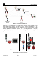
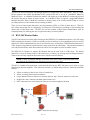
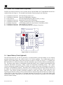
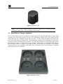
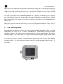
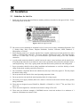
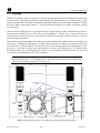
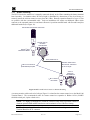
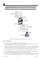
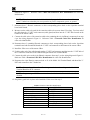
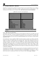
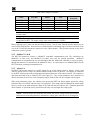
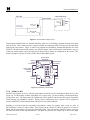
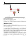
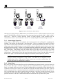
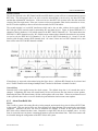
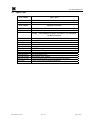
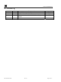
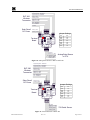
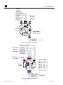
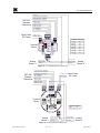
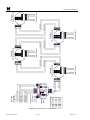
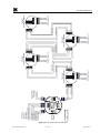


![[FR] - FEE DU LOGIS (Pliz) Surfaces modernes Nettoyant](http://vs1.manualzilla.com/store/data/006446107_1-191d720e2481d513d62b4e59270bcca9-150x150.png)