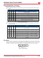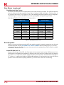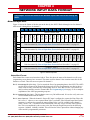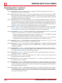
1
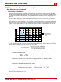
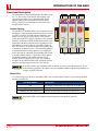
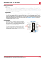
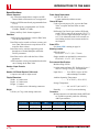
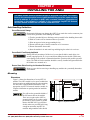
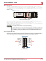
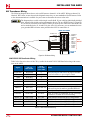
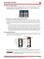
ADVANCED MICRO CONTROLS INC. User M Manual #: 940-0A050 al u n a GENERAL INFORMATION Important User Information The products and application data described in this manual are useful in a wide variety of different applications. Therefore, the user and others responsible for applying these products described herein are responsible for determining the acceptability for each application. While efforts have been made to provide accurate information within this manual, AMCI assumes no responsibility for the application or the completeness of the information contained herein. UNDER NO CIRCUMSTANCES WILL ADVANCED MICRO CONTROLS, INC. BE RESPONSIBLE OR LIABLE FOR ANY DAMAGES OR LOSSES, INCLUDING INDIRECT OR CONSEQUENTIAL DAMAGES OR LOSSES, ARISING FROM THE USE OF ANY INFORMATION CONTAINED WITHIN THIS MANUAL, OR THE USE OF ANY PRODUCTS OR SERVICES REFERENCED HEREIN. No patent liability is assumed by AMCI, with respect to use of information, circuits, equipment, or software described in this manual. The information contained within this manual is subject to change without notice. This manual is copyright 2012 by Advanced Micro Controls Inc. You may reproduce this manual, in whole or in part, for your personal use, provided that this copyright notice is included. You may distribute copies of this complete manual in electronic format provided that they are unaltered from the version posted by Advanced Micro Controls Inc. on our official website: www.amci.com. You may incorporate portions of this documents in other literature for your own personal use provided that you include the notice “Portions of this document copyright 2012 by Advanced Micro Controls Inc.” You may not alter the contents of this document or charge a fee for reproducing or distributing it. Standard Warranty ADVANCED MICRO CONTROLS, INC. warrants that all equipment manufactured by it will be free from defects, under normal use, in materials and workmanship for a period of [18] months. Within this warranty period, AMCI shall, at its option, repair or replace, free of charge, any equipment covered by this warranty which is returned, shipping charges prepaid, within eighteen months from date of invoice, and which upon examination proves to be defective in material or workmanship and not caused by accident, misuse, neglect, alteration, improper installation or improper testing. The provisions of the "STANDARD WARRANTY" are the sole obligations of AMCI and excludes all other warranties expressed or implied. In no event shall AMCI be liable for incidental or consequential damages or for delay in performance of this warranty. Returns Policy All equipment being returned to AMCI for repair or replacement, regardless of warranty status, must have a Return Merchandise Authorization number issued by AMCI. Call (860) 585-1254 with the model number and serial number (if applicable) along with a description of the problem during regular business hours, Monday through Friday, 8AM - 5PM Eastern. An "RMA" number will be issued. Equipment must be shipped to AMCI with transportation charges prepaid. Title and risk of loss or damage remains with the customer until shipment is received by AMCI. 24 Hour Technical Support Number 24 Hour technical support is available on this product. If you have internet access, start at www.amci.com. Product documentation and FAQ’s are available on the site that answer most common questions. If you require additional technical support, call (860) 583-7271. Your call will be answered by the factory during regular business hours, Monday through Friday, 8AM - 5PM Eastern. During non-business hours an automated system will ask you to enter the telephone number you can be reached at. Please remember to include your area code. The system will page an engineer on call. Please have your product model number and a description of the problem ready before you call. We Want Your Feedback Manuals at AMCI are constantly evolving entities. Your questions and comments on this manual are both welcomed and necessary if this manual is to be improved. Please direct all comments to: Technical Documentation, AMCI, 20 Gear Drive, Terryville CT 06786, or fax us at (860) 584-1973. You can also e-mail your questions and comments to [email protected] ADVANCED MICRO CONTROLS INC. TABLE OF CONTENTS General Information Important User Information ..................... Standard Warranty ................................... Returns Policy .......................................... 24 Hour Technical Support Number ........ We Want Your Feedback ......................... 2 2 2 2 2 About this Manual Audience .................................................. Applicable Units ...................................... Trademark Notices ................................... Revision Record ....................................... Revision History ............................ 5 Navigating this Manual ............................ Manual Conventions ................................ Where To Go From Here ......................... 5 5 5 5 5 6 6 Chapter 1: Introduction to the ANE2 AnyNET-I/O ............................................ The ANE2 ................................................ SSI protocol ............................................. ANE2 Programmable Parameters ............ SSI Setup Parameters .................... 9 SSI Clock Frequency ................. 9 Number of SSI Data Bits ........... 9 Number of Data Value Bits & MSB Number Parameters ............................... 9 Data Type .................................. 10 Data Logic ................................. 10 Data Setup Parameters ................... 10 Full Scale Count ........................ 10 Count Direction ......................... 10 Scalar Multiplier and Scalar Divisor .......................... 11 Preset Value .............................. 12 Velocity Update Time ............... 12 Channel Setup Parameters ............. 12 Channel LED Disable ............... 12 Channel Input Function ............. 12 Network Input Data Format ...... 13 Programming Cycle ................................. Front Panel Description ........................... Address Settings ............................ 14 Status LED’s .................................. 14 7 7 8 9 Chapter 1: Introduction to the ANE2 (continued) Power Connections ................................... 15 ANE2 Power ................................. 15 Sensor Power ................................ 15 I/O Connector ........................................... 15 Specifications ........................................... 16 Chapter 2: Installing the ANE2 Safe Handling Guidelines ........................ Prevent Electrostatic Damage ... 17 Prevent Debris From Entering the Module ............... 17 Remove Power Before Servicing ................................. 17 Mounting .................................................. Dimensions ................................... 17 Mounting the DIN Rail ................. 18 Installing IC-5 Connectors ............ 18 Mounting the ANE2 Module ........ 18 Addressing ................................................ Power Connector ...................................... I/O Connector Pin Out ............................. SSI Transducer Wiring ............................. AMCI DC25 SSI DuraCoder Wiring ...................... 20 Extending the Sensor Cable ..................... Avoiding Ground Loops When Extending the Sensor Cable ........ 21 Powering the SSI Sensor .......................... Input Wiring ............................................. 17 17 18 19 19 20 21 21 22 Chapter 3: Network Output Data Format Network Output Data ............................... 23 Command Word Format ............... 23 Configuration Word Format ......... 24 Data Words ............................................... 25 Sign-Magnitude Data Format ....... 26 Error Response ......................................... 26 Actual SSI Data is all 1’s .............. 26 13 14 Chapter 4: Network Input Data Format Network Input Data .................................. 27 Status Word Format ...................... 27 20 Gear Drive, Plymouth Ind. Park, Terryville, CT 06786 Tel: (860) 585-1254 Fax: (860) 584-1973 http://www.amci.com 3 TABLE OF CONTENTS Notes 4 ADVANCED MICRO CONTROLS INC. ABOUT THIS MANUAL Read this chapter to learn how to navigate through this manual and familiarize yourself with the conventions used in it. The last section of this chapter highlights the manual’s remaining chapters and their target audience. Audience This manual explains the set-up, installation, and operation of AMCI’s ANE2 AnyNET-I/O SSI Interface Module. It is written for the engineer responsible for incorporating these modules into a design, as well as the engineer or technician responsible for their actual installation. Applicable Units This manual applies to all ANE2 modules, including those that have an integral network connection. This includes the ANE2E which has an integral Ethernet port. This port allows the ANE2E to connect itself, and up to five other modules, to an EtherNet/IP or Modbus/TCP network. If you have an ANE2 module with a network interface, you will have to refer to the appropriate AnyNET-I/O Network Interface manual for information on connecting the module to your network. These manuals can be found in the PDF document section of our website at www.amci.com/documents.asp The AnyNET-I/O product line is constantly evolving. Check our website, www.amci.com for the latest information on available modules and network interfaces in the AnyNET-I/O line. Trademark Notices The AMCI logo and “AnyNET-I/O” are trademarks of Advanced Micro Controls Inc. All other trademarks contained herein are the property of their respective holders. Revision Record This manual, 940-0A050, is the initial release of this manual. It was first released December 14th, 2012. Revision History 940-0A050 Initial Release. Navigating this Manual This manual is designed to be used in both printed and on-line formats. Its on-line form is a PDF document, which requires Adobe Acrobat Reader version 7.0+ to open it. The manual is laid out with an even number of pages in each chapter. This makes it easier to print a chapter to a duplex (double sided) printer. Bookmarks of all the chapter names, section headings, and sub-headings were created in the PDF file to help navigate it. The bookmarks should have appeared when you opened the file. If they didn’t, press the F5 key on Windows platforms to bring them up. Throughout this manual you will also find blue text that functions as a hyperlink in HTML documents. Clicking on the text will immediately jump you to the referenced section of the manual. If you are reading a printed manual, most links include page numbers. The PDF file is password protected to prevent changes to the document. You are allowed to select and copy sections for use in other documents and, if you own Adobe Acrobat version 7.0 or later, you are allowed to add notes and annotations. 20 Gear Drive, Plymouth Ind. Park, Terryville, CT 06786 Tel: (860) 585-1254 Fax: (860) 584-1973 http://www.amci.com 5 ABOUT THIS MANUAL Manual Conventions Three icons are used to highlight important information in the manual: NOTES highlight important concepts, decisions you must make, or the implications of those decisions. CAUTIONS tell you when equipment may be damaged if the procedure is not followed properly. WARNINGS tell you when people may be hurt or equipment may be damaged if the pro- cedure is not followed properly. The following table shows the text formatting conventions: Format Description Normal Font Emphasis Font Font used throughout this manual. Font used the first time a new term is introduced. When viewing the PDF version of the manual, clicking on the cross reference text jumps you to referenced section. Cross Reference Where To Go From Here This manual contains information that is of interest to everyone from engineers to operators. The table below gives a brief description of each chapter’s contents to help you find the information you need to do your job. CHP Num. Chapter Title 1 INTRODUCTION TO THE ANE2 2 INSTALLING THE ANE2 3 NETWORK OUTPUT DATA FORMAT NETWORK INPUT DATA FORMAT 4 6 Intended Audience Anyone new to the ANE2. This chapter gives a basic overview of the features available on the unit, typical applications, and specifications. Anyone that must install an ANE2 on a machine. Includes information on mounting, grounding, and wiring specific to the module and SSI sensors. Anyone that needs information on the commands you must write to the ANE2 to set its configuration. Anyone interested in the format of the data you can read from the ANE2. ADVANCED MICRO CONTROLS INC. CHAPTER 1 INTRODUCTION TO THE ANE2 This manual is designed to get you quickly up and running with the ANE2 SSI Interface Module. It is possible to purchase an ANE2 with or without a network interface. This manual only covers the functionality unique to the ANE2. Information on connecting to the network interface is available in the appropriate AnyNET-I/O Network Interface manual available on our www.amci.com website. AnyNET-I/O The ANE2 is an addition to the AnyNET-I/O product line from AMCI. The concept of this product line is simple: specialty and/or high speed I/O that can be attached to any popular industrial network; hence the name AnyNET-I/O. AnyNET-I/O is designed for a broad range of applications, from small machines with a single control enclosure, to large machines that use distributed I/O extensively to minimize wiring costs. What makes the AnyNET-I/O line different is that all of the modules are available with or without a network interface. Eliminating the need for a separate networking module lowers the total cost of ownership for all applications, but especially for the cost sensitive small machines that only require one or two sophisticated functions. Like many modern controllers, AnyNET-I/O modules are designed to be DIN rail mounted. Up to six AnyNET-I/O modules can be stacked together and accessed over a single network interface. “Stacking” is accomplished through a small backplane connector that snaps into the DIN rail before the AnyNET-I/O modules are installed. These connectors allow the AnyNET-I/O modules to communicate with each other. To the network, the stack of modules appear as one continuous block of I/O words. Figure 1.1 AnyNET-I/O Module Stack The ANE2 The ANE2 is a two channel SSI interface module that accepts 12 to 48Vdc as its power source. Synchronous Serial Interface is an industry standard serial protocol for transmitting sensor data. The SSI protocol is most commonly used in rotary and linear distance sensors, but any type of data can be transmitted using the protocol. The ANE2 contains several parameters that allows the module to interface with any SSI sensor on the market today and extract the data value from it. This data value can be scaled and the value’s rate of change, or velocity, is calculated. Each channel of the ANE2 also contains a discrete DC input that can be used to capture the data value or preset it to a programmable value. The data value, velocity, and captured data value, are all available to the host controller. Communication is performed through ten input registers and ten output registers you have to assign to the module. The ANE2 can report the Data Value, Velocity, and Captured Data Value to your host controller. Additionally, the actual SSI data read from the sensor is also available so that your program can determine the state of any error bits the sensor may provide. 20 Gear Drive, Plymouth Ind. Park, Terryville, CT 06786 Tel: (860) 585-1254 Fax: (860) 584-1973 http://www.amci.com 7 1 INTRODUCTION TO THE ANE2 The ANE2 (continued) All configuration data is sent from your host controller over the network connection of the AnyNET-I/O stack. This allows you to: Configure the ANE2 from anywhere Store multiple setups on your machine, one for each type of sensor you use Copy setup data from one machine to another Design custom HMI interfaces for configuration and alignment that can simplify machine training, startup, and repair. SSI protocol The original SSI protocol specification defined a twenty-five bit serial data stream from the sensor that is synchronized to clock pulses generated by a controller such as the ANE2. The protocol defines minimum and maximum clock frequencies. (The sensor cable dictates the maximum allowable frequency for each application.) In addition to the clock frequency, the SSI protocol specifies signal timing and electrical characteristics. However, the protocol does not specify the content, or format, of the data bits. Since its introduction, several companies have chosen not to follow the twenty-five bit convention of the SSI protocol. For example, single turn rotary encoders typically use a thirteen bit transfer. Figure 1.2 below shows a typical SSI data transfer. t 1 TIDL = 800µS min. TINT t = 1/SSI 2 3 N-2 N-1 TM N Bit 1 MSB Bit 2 Bit 3 Bit (N-2) Bit (N-1) Bit (N) Bit 1 Bit 2 LSB Figure 1.2 SSI Transfer Sensor data is latched on the first falling clock edge. The most significant data bit is shifted out on first rising edge. Subsequent rising clock edges shift out the rest of the data. TINT is the total interogation time for the sensor. It is equal to t * N + 0.5t where t = 1/(SSI clock frequency) and N equals the number of data bits in the SSI stream. TM is the time that the last bit is valid, which is determined by the sensor. It is typically 12 to 20 microseconds. It must be at least 5 microseconds to be compatible with the ANE2. Also note that the diagram shows the last bit as data. The original SSI protocol specification defined this bit as a stop bit which is always low. AMCI is aware of several manufacturers that are using this bit position for data, so the ANE2 treats it as such. TIDL is the time between interogations and is controlled by the ANE2. The ANE2 guarentees a minimum of 800 microseconds between interogations. Your SSI sensor must have new data available within this time. Multi-word transfers are accomplished by holding the clock signal low for the TM time period and restarting the clock. This signals the transducer to transfer additional bits of data instead of restarting at bit 1. Because multi-word transfers is rarely used in applications, the ANE2 does not support this protocol. The ANE2 assumes the SSI data value is embedded somewhere in the data stream and that other information, such as error bits, may also be included. Configuration of the ANE2 is performed through the programmable parameters associated with each channel. 8 ADVANCED MICRO CONTROLS INC. 1 INTRODUCTION TO THE ANE2 ANE2 Programmable Parameters The ANE2 is configured by setting its Programmable Parameters. Each channel of the ANE2 has its own set of parameters, which allows the ANE2 to interface with two completely different SSI sensors. These parameters are broken down into three groups. SSI Setup Parameters – Six parameters that are used to extract the Data Value from the SSI bit stream. These parameters define the SSI clock speed, number of bits in the SSI stream, the position and length of the Data Value within the stream, and the format of the data. Data Setup Parameters – Six parameters that affect the Data Value and Velocity information. These parame- ters allow you to scale the Data Value, preset it to a programmable count, change the direction of increasing counts, set its rollover position in rotary applications, and set the update time of the Velocity information. Channel Setup Parameters – Three parameters that are used to enable or disable the channel’s LED, define the function of the channel’s discrete DC input, and define the data that is transmitted to the host controller. SSI Setup Parameters SSI Clock Frequency This parameter allows you to set the SSI clock frequency to one of four values: 125 kHz, 250 kHz, 500 kHz or 1 MHz. Consult your transducer documentation to determine its maximum operating frequency. Remember that the maximum SSI clock frequency is also dependent on the length of the transducer cable. The default value of 125 kHz will work in all applications. Number of SSI Data Bits This parameter sets the number of bits in the entire SSI data transfer. This parameter has a range of one to thirty-two. Its default value is twenty-four. Number of Data Value Bits & MSB Number Parameters As the examples show in figure 1.3, these two parameters tell the ANE2 where the Data Value is embedded in the SSI data stream. The Number of Data Value Bits parameter specifies the length of the data and the MSB Number parameter specifies the first bit of the Data Value in the SSI data stream. The default value of the MSB Number parameter is one. The default value for the Number of Data Value Bits parameter is twentyfour. The default values will work with AMCI multi-turn SSI DuraCoders as well as many other multi-turn rotary SSI encoders. SSI DATA BITS Number of Data Value Bits = 16 MSB Number = 6 Format used by AMCI SSI multi-turn DuraCoders Number of Data Value Bits = 24 MSB Number = 1 SSI DATA BITS Number of Data Value Bits = 12 Format used by AMCI SSI single turn DuraCoders MSB Number = 2 Figure 1.3 Data Value in SSI Data Stream Examples 20 Gear Drive, Plymouth Ind. Park, Terryville, CT 06786 Tel: (860) 585-1254 Fax: (860) 584-1973 http://www.amci.com 9 1 INTRODUCTION TO THE ANE2 ANE2 Programmable Parameters (continued) SSI Setup Parameters (continued) Data Type This parameter tells the ANE2 to interpret the Data Value as a binary number or as a gray code encoded number. The default is Binary. Data Logic This parameter is included to handle rare situations where the Data Value is reported with negative logic. If this parameter is set, the ANE2 will invert the data bits before performing any scaling. The default value is Positive, which means that the ANE2 will not invert the Data Value bits from the sensor. Data Setup Parameters Six parameters that affect the Data Value and Velocity information. These parameters allow you to scale the Data Value, preset it to a programmable count, change the direction of increasing counts, set its rollover position in rotary applications, and set the update time of the Velocity information. Full Scale Count The Full Scale Count parameter is important only if you are using a rotary encoder. If you have a linear device, such as a magneto-restrictive linear displacement sensor or a laser range finder, leave this parameter at its default value of zero. If you are using a rotary encoder, the Full Scale Count parameter sets the number of counts the ANE2 can expect before the position rolls over to zero. If this value is not set, or set incorrectly, the ANE2 will not be able to handle the roll over between the maximum value and zero correctly. The Full Scale Count parameter must be set to the total number of counts generated by the encoder. For example, the single turn SSI DuraCoder from AMCI is a twelve bit encoder by default. For this encoder, the Full Scale Count should be set to 212 = 4,096. For multi-turn encoders, the Full Scale Count parameter should be set to (the number of counts per turn) * (the total number of turns). For example, the multi-turn SSI DuraCoder from AMCI defaults to 4,096 counts per turn and 4,096 turns. In this example, the Full Scale Count should be set to 4,096 * 4,096 = 16,777,216. The SSI DuraCoders from AMCI are fully programmable with a software utility available on our website. While programming, you set the DuraCoder’s Full Scale Count parameter. When configuring the ANE2, make sure that the ANE2’s Full Scale Count parameter matches the DuraCoder’s Full Scale Count parameter. Count Direction The Count Direction parameter allows you to reverse the direction of travel needed to increase the Data Value. For simplicity’s sake, the two values for this parameter are called Positive and Negative. When this parameter is set to its default of Positive, the Data Value is not changed. When this parameter is set to Negative, the change in Data Value depends on the value of the Full Scale Count parameter. If the Full Scale Count parameter equals zero, a linear sensor is assumed and the Data Value is changed to (2n – (Data Value)), where ‘n’ is the value of the Number of Data Value Bits parameter. If the Full Scale Count parameter is non-zero, a rotary sensor is assumed. The Data Value is change to ((Full Scale Count - Data Value) MOD Full Scale Count). The modulus function is required to keep the zero position as zero. Changing this parameter will most likely change the Data Value reported by the ANE2. The only time this does not occur is if you are using a rotary encoder and the position is at zero when you reverse the count direction. Because of this, set the Count Direction parameter before you preset the Data Value. 10 ADVANCED MICRO CONTROLS INC. 1 INTRODUCTION TO THE ANE2 ANE2 Programmable Parameters (continued) Data Setup Parameters (continued) Scalar Multiplier and Scalar Divisor These two parameters are used to scale the Data Value before it is transmitted to the host controller. Both parameters have a default value of one and can range in value from 1 to 32,767. The Scalar Multiplier must be less than or equal to the Scalar Divisor. In other words, the ratio of Multiplier to Divisor cannot be greater than one. LDT Resolution The first example of their use is with linear displacement transducers (LDT’s), such as the ones available from Balluff and MTS. Each of these manufacturers have resolutions measured in µm/count. The ANE2 can easily convert these measurements to the US customary system of inches. Figure 1.4 below shows the Multiplier and Divisor values needed to convert from various metric resolutions to US customary resolutions. For example, to convert data from a LDT with 5µm/count resolution to 0.0005"/count resolution, use a Scalar Multiplier of 50 and a Scalar Divisor of 127. Desired Resolution 0.00005" 0.0001" 0.0002" 0.0005" 0.001" 5 10 100 50 25 1 µm 127 127 127 127 127 10 20 100 50 2 µm 127 127 127 127 125 25 50 5 µm 127 127 127 100 50 10 µm 127 127 100 20 µm 127 40 µm 0.002" 5 254 5 254 25 254 25 127 50 254 100 127 0.005" 1 127 2 127 5 127 10 127 20 127 40 127 = Desired resolution exceeds resolution of LDT. Figure 1.4 Common LDT Scalar Values Use the following procedure to calculate your Scalar Multiplier and Divisor values if either your LDT Resolution or Desired Resolution does not appear in the above table. Desired Resolution (counts/inch) Conversion Factor = ------------------------------------------------------------------------------LDT Resolution (counts/inch) 1) Convert your LDT resolution from µm to inches. For example, you are using a sensor with 1 µm resolution in your application. 1mm 1 inch 1µm -------------------- --------------------- = 0.00003937 inches/count = 25,400 counts/inch 1000µm 25.4 mm 2) Determine the number of counts per inch for the desired resolution. For example, 0.0001". 0.0001 inches/count = 10 000 counts/inch 3) Determine the Scalar Multiplier and Divisor values. 50 100 10,000 counts/inch Desired Resolution (counts/inch)-----------------------------------------------------------------------------= --------------------------------------------- = --------- = --------127 254 25,400 counts/inch LDT Resolution (counts/inch) Therefore, to use a sensor with 1 µm resolution and get 0.0001 inches per count resolution, use a Scalar Multiplier of 50 and a Scalar Divisor of 127. 20 Gear Drive, Plymouth Ind. Park, Terryville, CT 06786 Tel: (860) 585-1254 Fax: (860) 584-1973 http://www.amci.com 11 1 INTRODUCTION TO THE ANE2 ANE2 Programmable Parameters (continued) Data Setup Parameters (continued) Preset Value The Preset Value parameter gives you the ability to offset the Data Value. When you preset the Data Value, the ANE2 calculates an internal offset. The internal offset is the value needed to make the Data Value equal to the Preset Value. The default Preset Value is zero. Its range depends on the value of the Full Scale Count Parameter If the Full Scale Count is zero, the range of the Preset Value is ±268,435,455 If the Full Scale Count is not zero, the range of the Preset Value is 0 to (Full Scale Count – 1) The type of internal offset that is generated when you preset the Data Value is also affected by the value of the Full Scale Count. If the Full Scale Count is zero, the internal offset is a linear offset. The range of values that you will see in the Data Value will be shifted by the amount of the internal offset. For example, without a preset applied, the Data Value ranges from 0 to 100. If you are at position zero, and apply a Preset Value of 1,000, the Data Value will now range from 1,000 to 1,100. If the Full Scale Count is not zero, the internal offset is a circular offset. This offset shifts the zero point of the Data Value. It does not change the range of values that you will see from the Data Value. Programming this parameter does not change the Data Value. There is a separate command for presetting the Data Value to the Preset Value. This command uses the Apply Preset to Data Value bit in the Network Output Data as described in chapter 3 starting on page 23. Velocity Update Time Velocity data, which is the rate of change in the Data Value, is always reported to the network host in terms of counts per second. It is based on the scaled Data Value, not the value extracted from the SSI data stream. The Velocity Update Time parameter allows you to choose between 24 and 160 milliseconds between updates, with a default of 160 milliseconds. The 160 millisecond setting give you a better velocity average, while the 24 millisecond setting give you a faster response to accelerations. This parameter has no effect on the Data Value itself. Specifically, it does not alter how often the Data Value is updated in the Network Input Data. Channel Setup Parameters Channel LED Disable This parameter allows you to disable the channel’s status LED. This is most commonly done if the channel is unused. Network Input Data for the channel is unaffected, so it is possible to disable the channel’s status LED once it is configured and operating. The ANE2 ships from the factory with the channel 2 LED disabled. Channel Input Function This parameter allow you to choose the functionality of the channel’s discrete DC input. Your choices are: General Purpose Input. Its state is reported in the Network Input Data. The data bit is on when the input is receiving power. Apply Preset to Data Value. The Data Value is set equal to the programmed Preset Value. This can be programmed to occur on the rising edge of the input, the falling edge, or both edges. The calculated offset is stored in RAM and is lost when power is cycled to the ANE2. Capture Data Value. The Data Value can be captured and can be reported in the Network Input Data. This can be programmed to occur on the rising edge of the input, the falling edge, or both edges. 12 ADVANCED MICRO CONTROLS INC. INTRODUCTION TO THE ANE2 1 ANE2 Programmable Parameters (continued) Channel Setup Parameters (continued) Network Input Data Format The following values can be transmitted to the host controller in the Network Input Data: Data Value Velocity Captured Data Value Actual SSI Data There are only five data words available to each channel. Therefore the ANE2 can only transmit two values at a time. The Network Input Data Format parameter allows you to choose which values are transmitted. The ANE2 can take up to four milliseconds to accept a change in format and begin transmitting the newly selected values. If your network interface updates the Network Input Data at a rate faster than four milliseconds, it may take multiple reads before this change in selected values is seen. Programming Cycle New parameter values are written to the ANE2 through a Programming Cycle. A Programming Cycle consists of six steps and is controlled by the Transmit Bit in the Network Output Data and the Acknowledge Bit in the Network Input Data. 1) Write the new programming data into the registers assigned to the module with the Transmit Bit reset. This step insures that the correct data is in the registers before the Programming Cycle begins. 2) Set the Transmit bit. A Programming Cycle is initiated when this bit makes a 01 transition. 3) Once the ANE2 is done with the programming data, it will set any necessary error bits and the Acknowledge Bit in the Network Input Data. 4) Once you see the Acknowledge Bit set, check for any errors. The error bits are guaranteed valid while the Acknowledge Bit is set. 5) Respond to any errors and reset the Transmit Bit. 6) The ANE2 responds by resetting the Acknowledge Bit. The Programming Cycle is now complete. All parameters are checked before any of them are applied. If there is an error in the block of data, the ANE2 will only set the appropriate error bits in the Network Input Data. Parameters are not applied to the ANE2 until all of the data is correct. 20 Gear Drive, Plymouth Ind. Park, Terryville, CT 06786 Tel: (860) 585-1254 Fax: (860) 584-1973 http://www.amci.com 13 1 INTRODUCTION TO THE ANE2 Front Panel Description ADDRESS Address Settings The AnyNET-I/O platform allows you to connect up to six modules to a single network connection in what we call an AnyNET-I/O Stack. The DIP switches behind the front panel cover are used to set the address of the module within the AnyNET-I/O Stack. A module with a network interface, such as the ANE2E for Ethernet networks, communicates with the host and must have an address of zero. This address is set by having all of the DIP switches in their OFF position. (If you are using a single module, then it must have an address of zero.) The remaining modules in the stack should have their addresses set to their position in the stack by setting the corresponding DIP switch to its ON position. Figure 1.5 shows the correct addressing for three modules. The module on the left is an ANE2E and has its address set to zero. The remaining modules can be ANE2 modules with or without network interfaces and their addresses are set to one and two. ADDRESS ADDRESS The front panels of three ANE2 modules are shown in figure 1.5. The front cover is hinged on the bottom, and swings down to allow you to change the DIP switch address settings. The front panel also has the Status LED’s, which give you information on the state of the module and the sensors. STATUS CH 2 STATUS CH 2 STATUS CH 2 CH 1 CH 1 CH 1 2 Channel SSI Input 2 Channel SSI Input 2 Channel SSI Input Figure 1.5 ANE2 Front Panel If an ANE2 with a network interface has its address set to any value other than zero, its network interface is disabled. This allows you to use multiple modules with network interfaces in a single AnyNET-I/O Stack. Status LED’s As shown in figure 1.5, there are two Status LED’s, one for each channel. Table 1.1 below shows the blink patterns for each LED. LED Blink Pattern Description ON Blinking, short ON, long OFF Blinking, long ON, short OFF No change in Data Value, DC input state is not shown. Change in Data Value occurring. DC input is off. Change in Data Value occurring. DC input is on. Table 1.1 Channel Status LED’s Each Status LED can be disabled with an instruction from the host controller. 14 ADVANCED MICRO CONTROLS INC. 1 INTRODUCTION TO THE ANE2 Power Connections ANE2 Power Power connections for the ANE2 are made through a plug in connector on the bottom of the module. The mate for this connector is included with the ANE2. This connector also has a pin for attaching the module to chassis ground. Detailed information on ANE2 power wiring can be found in the Power Connector section of the installation chapter, starting on page 19. Sensor Power The sensor interface circuitry is opto-isolated from the rest of the ANE2. In order to maintain this isolation, the ANE2 has separate power pins for the sensors. This also give you the ability to power the ANE2 and sensors with power supplies that have two different voltage outputs. If you do not need this isolation, there are ANE2 power pins on the I/O connector that allow you to easily jumper power from the ANE2 to the sensors. Detailed information on sensor power wiring can be found in the Powering the SSI Sensor section of the installation chapter, starting on page 21. I/O Connector As shown in figure 1.6, the I/O Connector is located on the top of the module. All sensor connections are made at this connector as well as the channel’s discrete DC input. Power connections for the ANE2 are made through the connector on the bottom of the module. The mate for this connector is included with the ANE2. Spares are available from AMCI under the part number MS-2X11. They are also available from Phoenix Contact under their part number 173 88 98. ANE2 TOP VIEW J1 +PWROUTmod 11 SHIELD 10 –PWROUTmod 9 –IN1 8 Ch 1 +IN1 7 Sensor GNDsensor 6 +Vsensor 5 –DATA1 4 +DATA1 3 –CLK1 2 +CLK1 1 J2 11 10 9 8 7 6 5 4 3 2 1 +PWRINext SHIELD –PWRINext –IN2 Ch 2 +IN2 GNDsensor Sensor +Vsensor –DATA2 +DATA2 –CLK2 +CLK2 Front of ANE2 Figure 1.6 I/O Connector 20 Gear Drive, Plymouth Ind. Park, Terryville, CT 06786 Tel: (860) 585-1254 Fax: (860) 584-1973 http://www.amci.com 15 1 INTRODUCTION TO THE ANE2 Specifications Sensors Supported Any sensor that outputs data in single word SSI format. Multi-word transfers are not supported. Number of SSI bits transferred programmable from 1 to 32. SSI clock frequency programmable to 125 kHz, 250 kHz, 500kHz, or 1 MHz. Power Supply Requirements 12 to 48 Vdc ±20%, 2 watts maximum (without sensors) Channel DC Input Used as general purpose I/O, to preset the Data Value, or capture the Data Value on state change. Differential. 560 Vac/dc opto-isolated. Will withstand 3750VAC (RMS) for 60 seconds. (UL1577) Can be wired as single ended input. Accepts 3.5 to 27 Vdc without the need for an external current limiting resistor. 10mA current needed to turn input on. Binary and Gray Scale formats supported. Data Value ANE2 can be programmed to extract a Data Value from the SSI data stream. Data Value can be treated as a linear or rotary position. (Data Values that are not positions can be treated as linear values.) Status LED’s See Status LED’s starting on page 14. Data Value can be scaled to engineering units through use of Scalar Multiplier and Scalar Divisor parameters. Mounting Location DIN rail mount EN 05 022 - 35 x 7.5 (35 x 7.5 mm) Data Value can be offset with the Preset Value parameter. Single modules can optionally be mounted on EN 05 022 - 35 x 15 (35 x 15 mm) ANE2 calculates velocity information based on the rate of change in the Data Value Environmental Specifications Module rating of IP20. Number of Input Channels Two Location must conform to IEC Pollution Degree 2 and Over Voltage Category II designations. Number of I/O Words Required (16 bits each) 10 input words and 10 output words Input Power ....... 12 to 48Vdc, surge to 60Vdc without damage to module. Physical Dimensions Width: 0.9 inches max. Depth: 4.5 inches max. Height: 3.9 inches 5.0 inches min. with mating connectors Ambient Operating Temperature Weight 0.38 lbs. (0.17 kg.) with mating connectors Humidity ........... 0 to 95%, non-condensing 16 ........... -4° to 122°F (-20° to 50°C) Storage Temperature ........... -40° to 185°F (-40° to 85°C) Connectors Mating connectors are included with the ANE2 and are available separately under the following AMCI part numbers. Connector AMCI Part # Wire Strip Length Min. Tightening Torque I/O Power MS-2X11 MS-4M 28 - 16 AWG 28 - 12 AWG 0.275 inches 0.394 inches Spring Cage Connector 4.43lb-in (0.5 Nm) ADVANCED MICRO CONTROLS INC. CHAPTER 2 INSTALLING THE ANE2 The ANE2 module must be installed as part of an AnyNET-I/O stack. The instructions in this manual explain how to install the ANE2 as part of the stack and how to set its address. If you have an ANE2 with a network interface, information on connecting to the network is available in the appropriate AnyNET-I/O Network Interface manual available on our website, www.amci.com. Safe Handling Guidelines Prevent Electrostatic Damage Electrostatic discharge can damage the ANE2 if you touch the rear bus connector pins. Follow these guidelines when handling the module. 1) Touch a grounded object to discharge static potential before handling the module. 2) Work in a static-safe environment whenever possible. 3) Wear an approved wrist-strap grounding device. 4) Do not touch the pins of the bus connector or I/O connector. 5) Do not disassemble the module 6) Store the module in its anti-static bag and shipping box when it is not in use. Prevent Debris From Entering the Module During DIN rail mounting of all devices, be sure that all debris (metal chips, wire strands, tapping liquids, etc.) is prevented from falling into the module. Debris may cause damage to the module or unintended machine operation with possible personal injury. The DIN rail for the modules should be securely installed and grounded before the modules are mounted on it. Remove Power Before Servicing in a Hazardous Environment Remove power before removing or installing any modules in a potentially hazardous environment. Mounting 4.47" I/O Mating Connector (113.5) 0.89" (22.6) You will need to ground the shields of the SSI sensor cable at the module. There are two pins on the ANE2 to ground a shield, but if you have multiple shields, it may be better to ground them to the DIN rail. If you decide to do this, make sure your DIN rail is long enough to mount the AnyNET-I/O modules and ground the cable shields. 20 Gear Drive, Plymouth Ind. Park, Terryville, CT 06786 Tel: (860) 585-1254 Fax: (860) 584-1973 http://www.amci.com 4.55" (115.6) 3.90" (99.1) 4.47" ADDRESS Dimensions Figure 2.1 shows the dimensions of an AnyNET-I/O module. The ANE2 module is a low power module that does not require any additional spacing when mounting the unit. Refer to the installation instructions of the appropriate AnyNET-I/O network interface module for complete information on spacing needed to install the module. 0.26" (6.6) Figure 2.1 AnyNET-I/O Outline 17 2 INSTALLING THE ANR2 Mounting (continued) Mounting the DIN Rail Mounting the DIN rail is explained in the appropriate Network Interface manual. Please note that the DIN rail must be grounded for proper system operation. Installing IC-5 Connectors You need to install an IC-5 connector on the DIN rail to allow the ANE2 to communicate with the stack. Figure 2.2 shows how to install the IC-5 connectors in the DIN rail. Note the orientation of the IC-5 connectors when installing them. The module key goes towards the bottom of the DIN rail. If you are using a single ANE2 with a network interface, then you do not need the IC-5 connector. The connector is only used for communications within the stack. Figure 2.2 IC-5 Connector Installation Mounting the ANE2 Module Mounting an AnyNET-I/O module is a very simple process thanks to the design of the enclosure. 1) Partially engage the connector into the enclosure. 2) Engage the top lip of the enclosure with the top of the DIN rail and rotate the module down until the metal bracket snaps onto the DIN Rail. Once all of your modules are installed, it is strongly suggested to use the end caps from Phoenix Contact with the part number of 271 37 80 to secure the modules on the DIN Rail. These end caps prevent the module from sliding along the DIN rail if it is subjected to shock or vibration during machine operation. Addressing Each module needs to be given an address within the AnyNET-I/O Stack before the system will operate correctly. The address is set with the five position DIP switch on the front of the module. ADDRESS 3) If a module with a network interface has a non-zero address, then its network interface is disabled. ADDRESS 2) The module that has an address of zero must have a network interface and it is the only module in the stack that can have a direct connection to the network. ADDRESS 1) Only a single switch should be in the “ON” position when setting the address. Address =0 Address =1 Address =2 Figure 2.3 Addressing Example Figure 2.3 is a close up of three modules in an AnyNET-I/O Stack. The module on the left has a network interface and has an address of zero (All DIP switches off.) This module has the active network interface and connects the stack to the network. Reading left to right, the remaining modules have addresses of one and two respectively. If either of these module have a network interface, it is disabled. 18 ADVANCED MICRO CONTROLS INC. 2 INSTALLING THE ANR2 Power Connector The ANE2 accepts 12 to 48Vdc as its input power. As shown in the figure below, the power connector is located on the bottom of the module. The mating connector is included with the ANE2. Spares are available from AMCI under the part number MS-4M. They are also available from Phoenix Contact under their part number 187 80 37. +Vdc ANE2 Bottom View Area for Network Connections* DC Return DC Return Power Connector Figure 2.4 Power Connector Location Power connections should be tight, as loose connections may lead to arcing which will heat the connector. Phoenix Contact specifies a tightening torque of 4.4 to 5.4 lb-in (0.5 to 0.6 Nm). The power supply is connected to the pins marked “+Vdc In” and “DC Return”. The “Chassis GNDIN” pin is used to attach the ANE2 to earth ground. 1) Each ANE2 module must have its own power connection. 2) AnyNET-I/O modules are electrically isolated from the DIN rail by their mounting, but the Chassis GND connection is common to all of the modules in the stack through a pin in the IC-5 connector. At least one module in the AnyNET-I/O Stack must be attached to earth ground through a heavy gauge stranded wire to ensure reliable operation of the stack. I/O Connector Pin Out The I/O Connector is located on the top of the module. The mate for this connector is included with the ANE2. Spares are available from AMCI under the part number MS-2X11 and are also available from Phoenix Contact under their part number 173 88 98. Figure 2.5 shows the pin out for the I/O connector. ANE2 TOP VIEW J1 J2 +PWROUTmod 11 SHIELD 10 –PWROUTmod 9 –IN1 8 Ch 1 +IN1 7 Sensor GNDsensor 6 +Vsensor 5 –DATA1 4 +DATA1 3 –CLK1 2 +CLK1 1 11 10 9 8 7 6 5 4 3 2 1 +PWRINext SHIELD –PWRINext –IN2 Ch 2 +IN2 GNDsensor Sensor +Vsensor –DATA2 +DATA2 –CLK2 +CLK2 Front of ANE2 Figure 2.5 I/O Connector 20 Gear Drive, Plymouth Ind. Park, Terryville, CT 06786 Tel: (860) 585-1254 Fax: (860) 584-1973 http://www.amci.com 19 2 INSTALLING THE ANR2 SSI Transducer Wiring The following diagram shows how to wire an SSI sensor to channel 1 of the ANE2. Wiring to channel 2 is identical. Wire colors are not shown in the diagram because they are not standardized for SSI sensors. Refer to the documentation that is available for your sensor to determine the correct color code. The diagram shows a cable with a single overall shield. If your cable has individually shielded pairs, then all of the shields can be terminated to this pin. The two SHIELD pins, J1-10 and J210, are directly connected to the Chassis GNDIN pin of the power connector. If the shields cannot be terminated to the J1-10 and J2-10 pins of the I/O connector, you can terminate them to your grounded DIN rail at the same point that the ANE2 is connected to it. ANE2 TOP VIEW J1 +PWROUTmod 11 SHIELD 10 –PWROUTmod 9 –IN1 8 +IN1 7 GNDsensor 6 +Vsensor 5 –DATA1 4 +DATA1 3 –CLK1 2 +CLK1 1 Ch 1 Sensor J2 11 10 9 8 7 6 5 4 3 2 1 +PWRINext SHIELD –PWRINext –IN2 Ch 2 +IN2 GNDsensor Sensor +Vsensor –DATA2 +DATA2 –CLK2 +CLK2 Front of ANE2 Figure 2.6 SSI Sensor Wiring AMCI DC25 SSI DuraCoder Wiring Table below lists wire colors of the CSL-(x) cable for the AMCI DC25 SSI DuraCoder along with connections to the ANE2. Signal CSL-(x) Wire COlor Pin # J1 for CH1 J2 for CH2 GNDsensor +Vsensor –Data +Data –CLK +CLK BLU/RED RED/BLU WHT/BLU BLU/WHT WHT/ORN ORN/WHT 6 5 4 3 2 1 See Powering the SSI Sensor on page 21 for additional information on powering the sensor. SHIELD Bare Wire 10 or DIN rail Reset GRY/WHT No Conn. Count Dir. WHT/GRY See Note –RS485 Tx +RS485 Tx –RS485 Rx +RS485 Rx WHT/GRN GRN/WHT WHT/BRN BRN/WHT No Conn. No Conn. No Conn. No Conn. Shield must be connected to chassis ground. If wire will not fit in pin 10, attach to grounded DIN rail. 100mS positive pulse resets position to zero. Float, or connect to GNDsensor for CW increasing. Connect to +Vsensor for CCW increasing Serial interface used during DC25 configuration. Serial interface used during DC25 configuration. Serial interface used during DC25 configuration. Serial interface used during DC25 configuration. Notes Table 2.1 DC25 SSI DuraCoder Wiring 20 ADVANCED MICRO CONTROLS INC. 2 INSTALLING THE ANR2 Extending the Sensor Cable Your sensor manufacturer should have a suggested cable if you need to extend the sensor cable. If you cannot find a suggested cable, the following Belden cables can be used. Three is the minimum number of pairs needed for an SSI sensor. If your sensor has additional signals, then choose a cable with additional pairs. AMCI uses Belden 1423A for our CSL-(x) cable. Belden # # of Pairs 1420A 1421A 1422A 1423A 3 4 5 6 Table 2.2 Suggested Extension Cables Avoiding Ground Loops When Extending the Sensor Cable A ground loop occurs when the shields of a cable are attached to earth ground in two places. It is possible, and the likelihood increases as the cable length increases, for these two earth ground points to have a voltage potential between them. The shield acts as a low impedance path between the two points which results in a constant current flowing through the shield. To avoid a ground loop, the cable shields must not be grounded in two places. If the shield of the transducer cable is isolated from the body of the SSI sensor, connect the shield of the cable to the shields of the extension cable and ground the shield at the ANE2. Treat the shield of the sensor cable as a signal carrying conductor and do not connect it to earth ground at any other point. If the shield of the cable is connected to the body of the SSI sensor, but the body of the sensor is isolated from chassis ground by its mounting, connect the shield of the sensor cable to the shields of the extension cable and ground the shield at the ANE2. Treat the shields of the sensor cable and the extension cable as signal carrying conductors and do not connect them to earth ground at any junction point. Powering the SSI Sensor The SSI sensor interface electronics are electrically isolated from the reset of the ANE2 module. This gives you the ability to power the AnyNET-I/O stack with a different supply than the SSI sensors. Figure 2.7 below shows the power connections within the ANE2. Chassis GND +Vdc +PWROUTmod 11 SHIELD 10 –PWROUTmod 9 –IN1 8 Ch 1 +IN1 7 GND sensor 6 +Vsensor 5 –DATA1 4 +DATA1 3 –CLK1 2 +CLK1 1 DC Return J2 11 10 9 8 7 6 5 4 3 2 1 +PWR INext SHIELD –PWR INext –IN2 Ch 2 +IN2 GNDsensor +Vsensor –DATA2 +DATA2 –CLK2 +CLK2 ANE2 TOP VIEW Area for Network Connections J1 ANE2 BOTTOM VIEW Figure 2.7 Sensor Power Wiring In order to power the sensors, you must apply power to the ±PWRINext pins. This can be an external supply, or jumper pin J1-11 to J2-11 and pin J1-9 to J2-9 to power the sensor and ANE2 from the same supply. If the voltage used to power the ANE2 is higher that the sensor can accept, you must use an external supply to power the sensor. Jumpering ±PWROUTmod to ±PWRINext in this case will damage you SSI sensor. 20 Gear Drive, Plymouth Ind. Park, Terryville, CT 06786 Tel: (860) 585-1254 Fax: (860) 584-1973 http://www.amci.com 21 2 INSTALLING THE ANR2 Input Wiring Each channel has a differential DC input that can be programmed as a general purpose input, to preset the Data Value, or capture the Data Value. Figure 2.8 shows how to wire discrete DC differential, sourcing, and sinking sensors to the ANE2 inputs. Input Specifications: DC Differential Sensor Differential. 560 Vac/dc opto-isolated. Will withstand 6000 Vac/dc for 60 seconds. Can be wired as single ended inputs. Accepts 3.5 to 27Vdc without the need for an external current limiting resistor. +5Vdc to +24Vdc Isolated Power Supply Can use the same supply to power all inputs OUT+ OUT– – INPUT "n" + INPUT "n" – Grounding Strap maybe required by local safety codes. +IN –IN Input Optocoupler Figure 2.9 Simplified Input Schematic DC Sourcing Sensor +5Vdc to +24Vdc Isolated Power Supply Can use the same supply to power all inputs – INPUT "n" + INPUT "n" – Grounding Strap maybe required by local safety codes. Because they are low power signals, cabling from the discrete sensor to the ANE2 should be done using a twisted pair cable with an overall shield. The shield should be grounded at the end where the signal is generated, which is the sensor end. If this is not practical, the shield should be grounded to the same ground point as the ANE2, which is typically the DIN rail or the system ground bus. DC Sinking Sensor +5Vdc to +24Vdc Isolated Power Supply Can use the same supply to power all inputs. – INPUT "n" + INPUT "n" – Grounding Strap maybe required by local safety codes. Figure 2.8 Input Wiring 22 ADVANCED MICRO CONTROLS INC. CHAPTER 3 NETWORK OUTPUT DATA FORMAT This chapter covers the format of the Network Output Data that must be written to the ANE2 by your network host to configure the module. 10 9 8 7 6 5 4 3 2 1 0 0 Write Config: CH1 11 Write Config. CH2 12 Apply Preset to Data Value CH1 13 Apply Preset to Data Value CH2 14 Change Network Data Format: CH1 15 Change Network Data Format: CH2 Network Output Data Save to FLASH Memory 0 0 0 0 0 0 0 Data Logic Data Type Channel Input Function (See table 3.2 below.) Network Input Data Format (See table 3.3 below) Number of SSI Data Bits Range of 1 to 32, Default of 24. MSB Number Number of Data Value Bits Range of 1 to 32, Default of 1 Range of 1 to 28, Default of 24 Scalar Multiplier Range of 1 to {Scalar Divisor}, Default of 1 Scalar Divisor Range of 1 to 32,768, Default of 1 2 3 4 5 6 7 8 9 0 SSI Clk ƒ 00 = 125 kHz 01 = 250 kHz 10 = 500 kHz 11 = 1.0 MHz Count Direction 1 Velocity Update Time Configuration Word Disable Channel LED Network Output Data Word Numbers 0 Transmit Bit Command Word Sign Preset Value in sign-magnitude format (See figure 3.2 on page 26) Combined value of ±268,435,455 (±{228 – 1}), Default of 0 Full Scale Count in sign-magnitude format (See figure 3.2 on page 26) Combined value of 0, or 2 to 268,435,456 (228), Default of 0 Table 3.1 Network Output Data Format Command Word Format Bit 15, Transmit Bit - Used to control the flow of programming data to the ANE2. The ANE2 will not accept new programming data until this bit makes a 01 transition. Once this bit is set, it should remain set until the ANE2 responds by setting the Acknowledge bit in the Network Input data. See Programming Cycle on page 13 for a complete explanation of the ANE2 programming sequence. Bit 14, Save to FLASH Memory - This bit is used to store parameter values and calculated offsets into non- volatile FLASH memory. Once stored, the parameter values will be used on every power up. This means that you will not have to configure the ANE2 on every start up. The FLASH memory is limited to 10,000 write cycles. Do not save the offset to nonvolatile memory more than necessary to prevent a failure in the ANE2. Bits 13-6, Reserved - Must be set to ‘0’. A command error will result if any of these bits are set to ‘1’ when the Transmit Bit makes a 01 transition. 20 Gear Drive, Plymouth Ind. Park, Terryville, CT 06786 Tel: (860) 585-1254 Fax: (860) 584-1973 http://www.amci.com 23 3 NETWORK OUTPUT DATA FORMAT Network Output Data (continued) Command Word Format (continued) Bit 5, Change Network Data Format: CH2 - Set this bit to change the channel 2 data transmitted from the ANE2 to the host. The data transmitted is selected by the Network Input Data Format bits of the Configuration Word. Bit 4, Change Network Data Format: CH1 - Set this bit to change the channel 1 data transmitted from the ANE2 to the host. The data transmitted is selected by the Network Input Data Format bits of the Configuration Word. Bit 3, Apply Preset to Data Value: CH2 - Set this bit to preset the Data Value for channel 2. The Data Value will change to the last programmed Preset Value for channel 2. The Preset Value is programmed as part of the configuration data when bit 1 of this word, the Write Configuration: Channel 2 bit is set. If you want to change the Preset Value and set the Data Value to it in one cycle, then both of these bits must be set. Bit 2, Apply Preset to Data Value: CH1 - Set this bit to preset the Data Value for channel 1. The Data Value will change to the last programmed Preset Value for channel 1. The Preset Value is programmed as part of the configuration data when bit 0 of this word, the Write Configuration: Channel 1 bit is set. If you want to change the Preset Value and set the Data Value to it in one cycle, then both of these bits must be set. Bit 1, Write Configuration: CH2 - Set this bit to change the configuration for channel 2. All of the parameters in the remaining output words are programmed when this bit is set. Bit 0, Write Configuration: CH1 - Set this bit to change the configuration for channel 1. All of the parameters in the remaining output words are programmed when this bit is set. Configuration Word Format Bit 15, Disable Channel LED - Set this bit to ‘1’ to disable the channel’s front panel status LED. The channel will still operate and send data in the Network Input Data words associated with the channel. Bit 14, Reserved - Must be set to ‘0’. A command error will result if this bit set to ‘1’ when the Transmit Bit makes a 01 transition. Bits 13&12, SSI Clock Frequency - These two bits set the frequency of the channel’s SSI clock. The default frequency of 125KHz allows for the greatest sensor cable length. Also, increasing the frequency will not decrease the network transfer time to your host controller. The frequency should only be increased if your sensor cannot operate at 125KHz. Bit 11, Velocity Update Time - Set this bit to ‘0’ to have the velocity data update every 160 milliseconds. Set this bit to ‘1’ to have the channel’s velocity data update every 24 milliseconds. This parameter only affects the calculation rate of the Velocity data. It has no effect on the network transfer rate to and from your host controller. Bit 10, Count Direction - Set this bit to ‘0’ to have the count direction be the same as the SSI sensor’s. Set this bit to ‘1’ to have the count direction be the reverse of the sensor’s. Bit 9, Data Type - Set this bit to ‘0’ if your SSI sensor transmits its data in binary. Set this bit to ‘1’ if your SSI sensor transmits its data in Gray Code. Bit 8, Data Type - Set this bit to ‘0’ if your SSI sensor transmits its data using positive logic. Set this bit to ‘1’ if your SSI sensor transmits its data using negative logic. 24 ADVANCED MICRO CONTROLS INC. 3 NETWORK OUTPUT DATA FORMAT Network Output Data (continued) Configuration Word Format (continued) Bits 7–4, Channel Input Function - Use the table below to define the functionality of the channel’s discrete input. Bit 7 Bit 6 Bit 5 Bit 4 0 0 0 0 0 0 0 1 0 0 1 0 0 0 1 1 0 1 0 0 0 1 0 1 0 1 1 0 All other combinations Function General Purpose Input. State reported in network input data. (Factory Default) Apply Preset to Data Value on Rising Edge and save offset in RAM Apply Preset to Data Value on Falling Edge and save offset in RAM Apply Preset to Data Value on Both Edges and save offset in RAM Capture the Data Value on Rising Edge Capture the Data Value on Falling Edge Capture the Data Value on Both Edges Reserved Table 3.2 Function of Channel Input Bits 3–0, Network Input Data Format - Use the table below to define the data transmitted to the host in the Network Input Data. Bit 7 Bit 6 Bit 5 Bit 4 0 0 0 0 0 0 0 1 0 0 1 0 0 0 1 1 0 1 0 0 All other combinations Function Data Value in words 1 & 2 for channel 1, words 6 & 7 for channel 2 Actual SSI Value in words 3 & 4 for channel 1, words 8 & 9 for channel 2 (Factory Default) Data Value in words 1 & 2 for channel 1, words 6 & 7 for channel 2 Velocity Data in words 3 & 4 for channel 1, words 8 & 9 for channel 2 Velocity Data in words 1 & 2 for channel 1, words 6 & 7 for channel 2 Actual SSI Value in words 3 & 4 for channel 1, words 8 & 9 for channel 2 Data Value in words 1 & 2 for channel 1, words 6 & 7 for channel 2 Captured Value in words 3 & 4 for channel 1, words 8 & 9 for channel 2 Velocity Data in words 1 & 2 for channel 1, words 6 & 7 for channel 2 Captured Value in words 3 & 4 for channel 1, words 8 & 9 for channel 2 Reserved Table 3.3 Network Input Data Format Data Words With the exception of Output Word 3, which contains both the MSB Number and Number of SSI Data Bits parameters, the format of the data words is straight forward. When determining the value of word 3, consider convert the two parameter values to hexadecimal before combining them into one word. For example: MSB Number # of SSI Data Bits 24DECIMAL 2DECIMAL 16#18 16#02 Word 3: 16#0218 = 536DECIMAL Figure 3.1 Output Word 3 Value 20 Gear Drive, Plymouth Ind. Park, Terryville, CT 06786 Tel: (860) 585-1254 Fax: (860) 584-1973 http://www.amci.com 25 3 NETWORK OUTPUT DATA FORMAT Data Words (continued) Sign-Magnitude Data Format The Preset Value and Full Scale Count parameters can exceed sixteen bits in length. The ANE2 accepts these values in a thirty-two bit sign-magnitude format. Bit 15 of the data’s MSW is the sign bit. This bit must be ‘0’ for a positive value and a ‘1’ for a negative value. The remaining bits hold the absolute value, or magnitude, of the data. Figure 3.2 shows the difference between sign/magnitude and signed integer formats. Note that the Full Scale Count parameter is always positive. Sign/Magnitude Signed Integer MSW LSW Decimal Value MSW LSW 16#0010 16#0001 16#0000 16#0000 16#0000 16#8000 16#8000 16#8001 16#8010 16#0000 16#0000 16#FFFF 16#0001 16#0000 16#0001 16#FFFF 16#0000 16#0000 1,048,576 (220) 65536 65535 1 0 -1 -65535 -65536 -1,048,576 16#0010 16#0001 16#0000 16#0000 16#0000 16#FFFF 16#FFFF 16#FFFF 16#FFF0 16#0000 16#0000 16#FFFF 16#0001 16#0000 16#FFFF 16#0001 16#0000 16#0000 Figure 3.2 Sign/Magnitude Data Format Error Response If there is an error in the data sent to the ANE2, the module responds by setting the appropriate error bit in the Network Input Data. See the NETWORK INPUT DATA FORMAT chapter, starting on page 27 for a full explanation of the error bits. The only way to clear an error bit is to program the module correctly. A global “Clear Errors” bit does not exist. Actual SSI Data is all 1’s Because of the design of the ANE2, the ±Data input circuitry outputs a logic 1 to the ANE2 processor when an SSI sensor is not attached to the channel, or when the sensor is not powered. The Data Value will change to (2n-1) where ‘n’ is equal to the Number of Data Value Bits parameter and the Actual SSI data will change to (2x-1) where ‘x’ is equal to the Number of SSI Data Bits parameter. If you know that your sensor will not output these values under normal operating conditions, you can use these values for error checking. 26 ADVANCED MICRO CONTROLS INC. CHAPTER 4 NETWORK INPUT DATA FORMAT This chapter covers the format of the Network Input Data sent to the host by the ANE2. Network Input Data Figure 4.1 shows the format of the data sent to the host by the ANE2. Words 0 through 4 are for channel 1 while words 5 through 9 are for channel 2. 15 14 13 12 11 10 9 8 7 6 5 4 3 2 1 0 1 2 3 4 CH1 Value 2 Sign Bit CH1 Value 2 Sign Bit CH1 Motion Direction CH1 Velocity at Zero CH1 Cmd Error CH1 Config. Error CH1 SSI Setup Errors CH1 Scalar Errors CH1 Preset Value Error CH1 FSC Error CH1 FSC Exceeded Memory Error CH1 Input State CH1 Value Captured Heartbeat Channel 1 Value 1 Value determined by Network Input Data Format bit field. See table 3.3 on page 25. Channel 1 Value 2 Value determined by Network Input Data Format bit field. See table 3.3 on page 25. 6 7 8 9 CH2 Value 2 Sign Bit CH2 Value 2 Sign Bit CH2 Motion Direction CH2 Velocity at Zero CH2 Cmd Error CH2 Config. Error CH2 SSI Setup Errors CH2 Scalar Errors 0 CH2 Preset Value Error 0 CH2 FSC Error 0 CH2 FSC Exceeded 5 CH2 Input State Channel 2 Status Word CH2 Value Captured Network Input Data Word Numbers 0 Acknowledge Bit Channel 1 Status Word Channel 1 Value 1 Value determined by Network Input Data Format bit field. See table 3.3 on page 25. Channel 1 Value 2 Value determined by Network Input Data Format bit field. See table 3.3 on page 25. Figure 4.1 Network Input Data Status Word Format Each channel has a status word associated with it. These bits show the status of the channel as well as any programming errors that may have occurred. The status word for channel 1 also contains status bits for the module as a whole. These bits are not repeated for channel 2. Bit 15, Acknowledge Bit (Ch1 Only) - Used to control the flow of programming data to the ANE2. The ANE2 sets this bit in response to the Transmit bit being set by the host. Programming error bits in the two status words are only valid while the Acknowledge bit is set. Once this bit is set, it will remain set until your host controller reset the Transmit Bit. See Programming Cycle on page 13 for a complete explanation of the ANE2 programming sequence. Bit 14, Heartbeat Bit (Ch1 Only) - This bit changes state every 500 milliseconds. It is used to verify active net- work communications with the ANE2. Bit 13, Value Captured - When the channel’s discrete DC input is configured to capture the Data Value, this bit is set to ‘1’ whenever a new captured Data Value is available. If the Network Input Data Format parameter is configured to transmit the captured Data Value, it will be available in the channel’s Value 2 words. A 0 1 transition on the Transmit Bit is the only way to clear the Value Captured bits. This is accomplished by three writes to the first Network Output Data word in the following sequence: 16#0000, 16#8000, 16#0000. This will clear the Value Captured bits without changing any of the module’s programmable parameters. 20 Gear Drive, Plymouth Ind. Park, Terryville, CT 06786 Tel: (860) 585-1254 Fax: (860) 584-1973 http://www.amci.com 27 4 NETWORK INPUT DATA FORMAT Network Input Data (continued) Status Word Format (continued) Bit 12, CH Input State - Set to ‘1’ whenever power is applied to the channel’s discrete input. Reset to ‘0’ when power is removed from the input. Bit 11, Memory Error (Ch 1 Only) - Set to ‘1’ if the non-volatile memory in the ANE2 is corrupt. The ANE2 leaves the factory with reasonable parameter defaults. This error may be a sign of a problem in the installation environment, such as high electrical noise. Attempt to reprogram the ANE2. If this fails, call AMCI technical support for assistance. Bit 10, FSC Exceeded - Set to ‘1’ if the Data Value ever exceeds the programmed Full Scale Count Value. This error condition does not exist if the Full Scale Count parameter is left at its default value of zero. Once set, this bit will remain set until the Full Scale Count parameter is reprogrammed or power to the ANE2 is cycled. The Full Scale Count parameter is only used in rotary encoder applications. See Full Scale Count on page 10 for a full description of how to use this parameter. Bit 9, FSC Error - Set to ‘1’ if you attempt to program the Full Scale Count parameter outside of its range of 0, or 2 to 268,435,456. The Full Scale Count parameter is only used in rotary encoder applications. See Full Scale Count on page 10 for a full description of how to use this parameter. Bit 8, Preset Value Error - Set to ‘1’ if the Preset Value data is not in sign-magnitude format. See Sign-Mag- nitude Data Format on page 26 for examples of sign-magnitude format. When the Full Scale Count Parameter equals zero, this bit is set to ‘1’ if you attempt to program the Preset Value parameter outside of its range of ±268,435,455. When the Full Scale Count Parameter does not equal zero, this bit is set to ‘1’ if you attempt to program the Preset Value parameter outside of its range of 0 to (Full Scale Count - 1). Bit 7, Scalars Error - Set to ‘1’ if the Scalar Divisor parameter is outside of its range of 1 to 32,767 or if the Scalar Multiplier is outside of its range of 1 to (Scalar Divisor). Bit 6, SSI Setup Error - Set to ‘1’ if the Number of SSI Bits, MSB Number, or Number of SSI Data Value Bits parameters are outside their valid ranges. Also set if (MSB Number + {Number of Data Value Bits-1} > Number of SSI Bits). Bit 5, Configuration Error - Set to ‘1’ if the bit fields that set the Channel Input Function or Network Input Data Format are set to any invalid combinations. Valid combinations for these bit fields are given in the Configuration Word Format section starting on page 24. Bit 4, Command Error - Set to ‘1’ if any of the reserved bits in the Network Output Data are set when the Transmit bit makes a 01 transition. Bit 3, Velocity at Zero - Set to ‘1’ if the velocity data equals zero. This bit is set even if the velocity data is not being transmitted to the host by the ANE2. Bit 2, Motion Direction - Set to ‘0’ if motion is increasing. Set to ‘1’ if motion is decreasing. This bit stays in its last state if there is no motion. Bit 1, Value 2 Sign Bit - Set to ‘1’ if the data transmitted as Value 2 is negative. The absolute value of Value 2 is transmitted in its data words. In order to accommodate host controllers that do not support thirtytwo bit signed integers, values from the ANE2 are transmitted in sign-magnitude format with this bit as the sign of the channel’s Value 2. Bit 0, Value 1 Sign Bit - Set to ‘1’ if the data transmitted as Value 1 is negative. The absolute value of Value 1 is transmitted in its data words. In order to accommodate host controllers that do not support thirtytwo bit signed integers, values from the ANE2 are transmitted in sign-magnitude format with this bit as the sign of the channel’s Value 1. 28 ADVANCED MICRO CONTROLS INC. NETWORK INPUT DATA FORMAT 4 Notes 20 Gear Drive, Plymouth Ind. Park, Terryville, CT 06786 Tel: (860) 585-1254 Fax: (860) 584-1973 http://www.amci.com 29 ADVANCED MICRO CONTROLS INC. LEADERS IN ADVANCED CONTROL PRODUCTS