1
ELSPEC G4500
BLACKBOX
Portable
Issue 1.2
August 2010
©2009 Elspec Ltd, All rights reserved.
All product names are trademarks of their respective companies
G4500 BLACKBOX PORTABLE OPERATIONAL MANUAL August 2010
Warranty Notice
Each Elspec product is warranted to be free from defects in material and workmanship under normal use and service. The warranty period is one year and begins on the date of shipment. Parts, product repairs, and services are warranted
for 90 days. This warranty extends only to the original buyer or end-user customer and does not apply to fuses, disposable batteries, or to any product which,
in Elspec's opinion, has been misused, altered, neglected, contaminated, or damaged by accident or abnormal conditions of operation or handling. Elspec warrants that the software will operate substantially in accordance with its functional
specifications for 90 days and that it has been properly recorded on nondefective media. Elspec does not warrant that the software will be error free and
operate without interruption.
Elspec authorized resellers shall extend this warranty on new and unused prodcts
to end-user customers only but do not have authority to extend a greater or different warranty on behalf of Elspec. Warranty support is available only if the
product is purchased through an Elspec authorized sales outlet or Buyer has paid
the applicable international price. Elspec reserves the right to invoice Buyer for
importation costs of repair/replacement parts when the product is purchased in
one country are submitted for repair in another country.
Elspec’s warranty obligation is limited, at Elspec's option, to refund of the purchase price, free of charge repair, or replacement of a defective product which is
returned to Elspec within the warranty period.
To obtain warranty service, contact Elspec directly to obtain return authorization
information, and then send the product to Elspec, with a description of the problem, postage and insurance prepaid (FOB destination). Elspec assumes no risk
for damage in transit. Following warranty repair, the product will be returned to
the Buyer, transportation prepaid (FOB destination). If Elspec determines that
the failure was caused by neglect, misuse, contamination, alteration, accident, or
abnormal condition of operation of handling, including overvoltage failures
caused by use outside the product's specified rating, or normal wear and tear of
mechanical components, Elspec will provide an estimate of repair costs and obtain authorization before commencing work. Following repair, the product will
be returned to the Buyer, transportation prepaid, and the Buyer will be billed for
the repair and return postage transportation charges (FOB Shipping Point).
This warranty is the Buyer's sole and exclusive remedy and is in lieu of all other
warranties, express or implied, including but not limited to any implied warranty
of merchantability or fitness for a particular purpose. Elspec shall not be liable
for any special, indirect, incidental, or consequential damages or losses, including loss of data arising from any cause or theory.
Since some countries or states do not allow limitation of the term of an implied
warranty, or exclusion or limitation of incidental or consequential damages, the
Elspec | Warranty Notice
i
August 2010
G4500 BLACKBOX PORTABLE OPERATIONAL MANUAL
limitations and exclusions of this warranty may not apply to every buyer. If any
provision of this Warranty is held invalid or unenforceable by a court or other
decision-maker of competent jurisdiction, such holding will not affect the validity or enforceability of any other provision.
ii
Warranty Notice | Elspec
G4500 BLACKBOX PORTABLE OPERATIONAL MANUAL August 2010
Table of Contents
WARRANTY NOTICE .................................................................................................... I
TABLE OF CONTENTS ............................................................................................... III
INTRODUCTION............................................................................................................ 1
SAFETY INFORMATION .............................................................................................. 2
THE HARDWARE .......................................................................................................... 3
Specifications ................................................................................................ 3
Physical Dimensions ...................................................................................... 7
Default Accessories ....................................................................................... 8
Optional Accessories ....................................................................................11
3000 Amp Flexible Current Clamp ............................................................................. 11
300 Amp Flexible Current Clamp ............................................................................... 11
Mini Clamp – 1 to 6 Amp ........................................................................................... 11
Mini Clamp – 100 Amp .............................................................................................. 12
Controls and Indicators ................................................................................12
Front Panel................................................................................................................. 12
Rear Panel .................................................................................................................. 13
Reference ....................................................................................................14
Voltage Inputs ............................................................................................................ 16
Fast AC/DC Channels ................................................................................................. 16
Indication ................................................................................................................... 17
Auxiliary DC Voltage Channel .................................................................................... 17
DC Voltage Specifications .......................................................................................... 17
Current Inputs ..............................................................................................18
AC Current Channels .................................................................................................. 18
Elspec | Table of Contents
iii
August 2010
G4500 BLACKBOX PORTABLE OPERATIONAL MANUAL
Auxiliary AC/DC Current Channel ...............................................................................19
Power Type Diagrams .................................................................................. 19
Single Phase with Neutral ..........................................................................................19
Single Phase without Neutral .....................................................................................20
Single Split Phase .......................................................................................................20
Three Wire Delta ........................................................................................................21
Four Wire WYE ...........................................................................................................21
Three Wire WYE .........................................................................................................22
Delta High Leg ............................................................................................................22
Delta Open Leg ...........................................................................................................23
Power Supply............................................................................................... 24
Main Power ................................................................................................................24
Auxiliary Power Supply ..............................................................................................25
Status Indications ........................................................................................ 25
Battery Status Indicator .............................................................................................25
Operation ON/OFF Switch’s Indicator .......................................................................26
Operational Status Indicator ......................................................................................26
Internal UPS ...............................................................................................................26
Grounding ................................................................................................... 27
Networking.................................................................................................. 28
Ethernet Ports View ...................................................................................................28
Serial Communication ................................................................................................31
Temperature Sensor .................................................................................... 34
Digital Inputs ............................................................................................... 34
Pin Description ...........................................................................................................35
Reset Button ................................................................................................ 35
WIRELESS ROUTER ................................................................................................... 36
Factory Default Setup .................................................................................. 37
iv
Table of Contents | Elspec
G4500 BLACKBOX PORTABLE OPERATIONAL MANUAL August 2010
WEBSITE ....................................................................................................................... 42
Access ..........................................................................................................42
Login Page ...................................................................................................43
Low Bandwidth ............................................................................................44
System Limitations .......................................................................................44
The Site Structure.........................................................................................46
Monitoring Section.......................................................................................47
Graphic Data Representation .................................................................................... 54
Energy Section .............................................................................................55
Consumption & Demand ........................................................................................... 55
Detailed Info .............................................................................................................. 57
Measurement Status ................................................................................................. 58
TDD ............................................................................................................................ 59
Power Quality Section ..................................................................................60
The Compliance Info Page ......................................................................................... 64
The Compliance Chart Page ....................................................................................... 65
The User Defined Pages ............................................................................................. 65
Service Section .............................................................................................66
Unit Setup .................................................................................................................. 67
Network Setup ........................................................................................................... 70
Power Setup............................................................................................................... 75
Events Setup .............................................................................................................. 80
Display Setup ............................................................................................................. 88
Firmware Upgrade ..................................................................................................... 88
Multi-IO Section ...........................................................................................96
LCD Section ..................................................................................................97
TIME SYNCHRONIZATION ....................................................................................... 97
Elspec | Table of Contents
v
August 2010
G4500 BLACKBOX PORTABLE OPERATIONAL MANUAL
INTEGRATED FTP SERVER .................................................................................. 102
Login ......................................................................................................... 103
System limitations ..................................................................................... 106
The File Structure ....................................................................................... 106
PQZip Files ................................................................................................. 107
INTEGRATED TELNET SERVER .......................................................................... 108
Telnet Client Application ............................................................................ 109
Establishing a Telnet Session ...................................................................... 111
Telnet Commands ...................................................................................... 111
PQZIP RECORDING ................................................................................................. 111
Principle of Operation ................................................................................ 112
Operation .................................................................................................. 113
Configuration ............................................................................................. 114
Enabling/disabling ................................................................................................... 115
FIFO Concept ........................................................................................................... 115
Fixed Quality versus Fixed Ratio ............................................................................. 116
File Capacity ............................................................................................................ 117
Record Mode .......................................................................................................... 117
Record Type ............................................................................................................ 119
Erasing All PQZip Data ............................................................................................. 119
THE SOFTWARE ...................................................................................................... 119
PQSCADA Suite .......................................................................................... 119
PQSCADA Server ........................................................................................ 120
PQSCADA Management Studio ................................................................... 121
Administration Console .......................................................................................... 122
vi
Table of Contents | Elspec
G4500 BLACKBOX PORTABLE OPERATIONAL MANUAL August 2010
Components.............................................................................................................122
The Node Status Fields ............................................................................................123
Elspec Investigator ..................................................................................... 129
Getting Started ........................................................................................................130
Adding a Measurement SITE ....................................................................................130
Operation .................................................................................................................134
Elspec Search Utility ................................................................................... 138
Obtaining the Search Utility .....................................................................................138
Operation .................................................................................................................139
Limitations ...............................................................................................................141
Useful Features ........................................................................................................141
HOW TO….? ............................................................................................................... 142
Replacing the Battery ................................................................................. 142
Before You Begin .....................................................................................................143
Removing the Battery ..............................................................................................144
Installing the New Battery .......................................................................................146
Disabling Proxy Server in Internet Explorer ................................................. 147
Establishing a Security on Wireless Interface ............................................... 150
WPA Configuration Example ....................................................................................151
Restore Wireless Router to Factory Defaults ............................................... 153
Simplified Power Curve Verification (PCV) Report ....................................... 154
Configuration ...........................................................................................................156
The Outcome ...........................................................................................................156
Producing a Simple Time of Use (TOU) Energy Report.................................. 159
Configuration ...........................................................................................................159
The Outcome ...........................................................................................................160
Elspec | Table of Contents
vii
G4500 BLACKBOX PORTABLE OPERATIONAL MANUAL August 2010
Introduction
The ELSPEC G4500 BLACKBOX Portable is the next generation in electrical
Power Quality recorders and analyzers. Powered by revolutionary PQZip1 compression technology, the G4500 BLACKBOX is capable of recording up to 1000
times more information than competitive instruments with equivalent memory
sizes. Practically, the G4500 BLACKBOX is designed to store continuously, cycle by cycle, all parameters of data, including waveforms at maximum resolution
for more than a year, internally, without the need of an external storage device or
computer. The integrated PQSCADA software package provides an innovative
and convenient way of performing even the most complicated power quality investigations. A State of the Art PQSCADA Investigator application helps to explore power quality events, zooming in and out on any parameter at High Definition resolution, from months to microseconds in mouse-click speed and simplicity.
The following are key features of the G4500 BLACKBOX Portable:
1
No field setup required: Powered by a unique, continuous all-parameters recording
with self-identifying current probes, the BLACKBOX Portable does not require any
field setup or configuration for most of the usage scenarios (except PT/CT ratios)
8 GB of internal memory: Capable of storing more than a year of continuous, allinclusive data with 1024 samples per cycle resolution for AC voltages and 256 samples
per cycle resolution for currents
Integrated WEB server: and wireless Wi-Fi router and access point for the most convenient control and operation
Refer to “PQZip” chapter on page 106 for more information
Elspec | Introduction
1
August 2010
G4500 BLACKBOX PORTABLE OPERATIONAL MANUAL
Mobile Analysis Lab A Touch screen, LCD display for setup, control, and comprehensive power quality analysis which offers a full Tablet PC functionality
Up to 9 AC measurement channels 4 AC/DC Voltages, 52 AC currents
Additional 2 DC measurement channels Additional DC Voltage and DC current
channels for simultaneous primary/secondary assessment of DC voltage converters
Internal and external (PT100) temperature recording Internal and (optional) external temperature is recorded during the entire measurement session
Superior time synchronization Ultimate time synchronization abilities for the most accurate multi-point assessment
Integrated rechargeable battery For up to 2 hours of self-powered operation
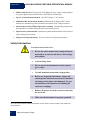
Safety Information
To avoid electrical shock or fire:
2
Review the entire manual before using the Instrument and its accessories and observe all warnings
and cautions.
Avoid working alone.
Do not operate the Instrument around explosive
gas or vapor.
Use only insulated current and voltage probes.
Before use, inspect the Instrument, voltage and
current probes, leads and accessories for mechanical damage, and replace when damaged. Pay special attention to the insulation surrounding the
connectors and plugs.
Remove all probes, test leads, and accessories that
are not in use.
Make sure the Instrument is properly grounded
th
A 5 , DC current channel could be operated for “Earth” AC/DC current recording in 256 samples per
cycle resolution.
2
Safety Information | Elspec
G4500 BLACKBOX PORTABLE OPERATIONAL MANUAL August 2010
through the power cord to protective earth ground.
Do not apply input voltages above the rating of the
Instrument as shown on the name plate.
Do not insert metal objects into connectors and
openings.
Never open Instrument’s enclosure during operation; dangerous voltages are present.
Use the Instrument only as specified in this manual, or the protection provided by the Instrument
may be impaired.
Do not expose the Instrument to extreme moisture
and or rain.
Do not operate the Instrument or its accessories
when found wet for any reason.
All accessories, including external probes, should
be UL Listed.
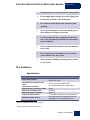
The Hardware
Specifications
General
Power Requirements
Operation Time during Interruptions
(internal UPS operation)
Internal memory capacity for data
Maximum recording period
Maximum Number of Events
Typical recording period
Real-time clock accuracy
3
Based on 700MB per month PQZip settings
4
Required high accuracy GPS time source
100-240V RMS ±10% 47-63Hz, 35W
48VDC (35- 55V)
>2 hours on fully charged battery
25 seconds minimum on empty battery
32 GB
Unlimited
Unlimited
3
12 months of continuous, every cycle data
Non synchronized: Not more than ±1s/day
4
Synchronized : up to ±50uS all times
Elspec | The Hardware
3
August 2010
G4500 BLACKBOX PORTABLE OPERATIONAL MANUAL
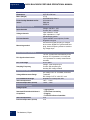
Clock/Calendar
Dimensions
Mass (Weight)
Power Quality Standard conformance
Leap years, 24-hour clock
250 x 60 x 300 mm
3.7 kg
IEC61000-4-30 Class A
IEC61000-4-15
EN50160
IEEE519
Voltage and Current Inputs
Input channels
Voltage channels
Current channels
Measuring method
Voltage: 4AC/DC + 1DC
Current: 4AC + 1AC/DC
Input resistance: 3 MΩ
Input capacitance: < 20pF
Self-identifying probes
Types available: current probes, flexible
Rogowski coil types
Simultaneous digital sampling of voltages
and currents. Digital PLL synchronized sampling, internal frequency reference used during voltage drops.
Synchronization and sampling
PLL-Synchronized source
PLL Lock Range
Sampling Frequency
The PLL synchronized automatically to the
best out of L12 (between L1-L2 lines) and
L3-G (between L3 to earth) measurement
channels
42.5 to 69Hz
Voltage: 1024 samples/cycle
Current: 256 samples/cycle
Auxiliary DC Voltage: 200mS
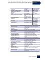
Measurement Ranges
Voltage Measurement Range
Current Measured Range
Internal temperature
External temperature (PT100)
AC Voltage: CAT III* 1kV RMS, 3mA ±8kV
Transients
DC Voltage: CAT III* ±1kV DC, 3mA
Depends on current probe used
-40C° : +125C°
-100C° : +99C°
Measurement Accuracy
Voltage Inputs
Standard IEC 61000-4-30 Class A
Compliance
Internal temperature
External temperature (PT100)
4
The Hardware | Elspec
• Aggregations
• Time Clock Uncertainty
• Flagging
• Transient Influence Quantities
≤1%
≤1%
G4500 BLACKBOX PORTABLE OPERATIONAL MANUAL August 2010
Frequency
Magnitude of Supply Voltage
Under-Deviation and OverDeviation
Flicker
Supply Voltage Dips and Swells
Uncertainty
±10 mHz
±0.1% of Udin
±0.1% of Udin
Voltage Interruptions
Unbalance
±5% of reading
Magnitude: ±0.2% of
Udin
Duration: ±1 cycle
Duration: ±1 cycle
±0.15%
Harmonics
IEC 61000-4-7 Class I
Interharmonics
IEC 61000-4-7 Class I
Measuring Range
42.5 Hz – 69 Hz
10% – 150% of
Udin
10% – 150% of
Udin
0.2 – 10 Pst
N/A
N/A
0.5% – 5% u2
0.5% – 5% u0
10% – 200% of
Class 3 of
IEC 61000-2-4
10% – 200% of
Class 3 of
IEC 61000-2-4
Transient Voltage detection
Measurement type
Full scale
Sample resolution
Interfaces
Color display
Optional B/W display
Integrated WEB server
Integrated FTP server
Integrated Telnet server
Communication
Ethernet Ports
Power Over Ethernet (PoE)
Wi-Fi interface
Serial Interface
Digital I/O
Relay
Extension slot
Supported Protocols
Wireless Security
1024 samples/cycle wave shape sampling,
no peak detect
8000 V pk
19.5uSec (50Hz) 16uSec (60Hz).
Touch screen “Mobile Analysis Lab” with
complete tablet PC functionality
PoE self powered G4100 display
Full control and real time monitoring
A standard interface for a main storage
memory
Command line control and troubleshooting
3 x 10/100Mb Fast Ethernet Ports,
Integrated router, NAT and Firewall
Available as output,31Watt
802.11 b/g with integrated antenna
1 x RS-232, 1 x RS-485
4 x 5-24VDC digital inputs
1 x 150V, 10A
1xPCMCIA
HTTP, FTP, TELNET, OPC DA, Modbus
RTU,
WEP, WPA(TKIP), WPA2(AES),
WPA2(Mixed)
Elspec | The Hardware
5
August 2010
G4500 BLACKBOX PORTABLE OPERATIONAL MANUAL
Environmental and safety Specifications
Operating Environment
Storage Temperature and
Humidity
Operating Temperature and
Humidity
Enclosure Protection
Standard Conformance
EMC
Safety
Indoors or in covered area outdoors, up to
2000 m latitude
-20 °C to 60 °C, 80% rh max, noncondensing
0 °C to 50 °C, 80% rh max, non-condensing
IP30 (per EN 60529)
EN61326
FCC part 15, subpart B
EN61010-1 (Ed.2, 2001)
* INTENDED USE Measurement Category – CATIII: Performing voltage and
current measurements inside electrical cabinets, on distribution boards, circuit
breakers, wires, cables in fixed installations, etc.
6
The Hardware | Elspec
G4500 BLACKBOX PORTABLE OPERATIONAL MANUAL August 2010
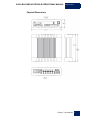
Physical Dimensions
Elspec | The Hardware
7
G4500 BLACKBOX PORTABLE OPERATIONAL MANUAL
August 2010
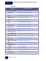
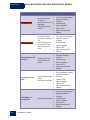
Default Accessories
The following are the standard accessories that come shipped with the device:
Qty
8
Part
Number
Description
1
SNT-10100000
Mobile Analysis Lab with
complete tablet PC functionality
1
MEB-29990000
Trolley Carrying Case
1
SOF-4000xxxx
PQSCADA– Power Quality
Management Software Enterprise Edition installation
CD
4
SOA-90453001
Flexible AC current clamps
3000A (Diameter: 80 CM
cable length: 2M)
1
EAH-41235100
AC Voltage Cord with Crocodile Clip + Fuse (1.2M)
1
EAH-41235200
Red AC Voltage Cord with
Crocodile Clip + Fuse (1.2M)
1
EAH-41235300
Blue AC Voltage Cord with
Crocodile Clip + Fuse( 1.2M)
1
EAH-41235400
Yellow AC Voltage Cord with
Crocodile Clip + Fuse(1.2M)
The Hardware | Elspec
Illustration
G4500 BLACKBOX PORTABLE OPERATIONAL MANUAL August 2010
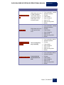
1
EAH-41239500
Green AC Voltage Cord with
Crocodile Clip(1.2M)
1
EAH-41235100
Black DC Voltage Cord with
Crocodile Clip + Fuse (1.2M)
1
EAH-41235200
Red DC Voltage Cord with
Crocodile Clip + Fuse (1.2M)
1
ENT-10020190
48VDC terminal block connector (RoHS Compliant)
1
ENT-10020191
Temperature Sensor terminal
block connector PT100 type
(RoHS Compliant)
1
ENT-10040190
RS485/422 Communication
terminal block connector
(RoHS Compliant)
1
ENT-20080190
Multi IO terminal block connector (RoHS Compliant)
1
TOE-00100013
LAN communication cord
length: 2M
EPC-20122190
Power Cable for Cont. Europe 10A/125V, straight,
1.8M, Black
EPC-70122190
Power Cable for North America 10A/125V, straight, 1.8M,
Black
1
Elspec | The Hardware
9
August 2010
10
G4500 BLACKBOX PORTABLE OPERATIONAL MANUAL
The Hardware | Elspec
G4500 BLACKBOX PORTABLE OPERATIONAL MANUAL August 2010
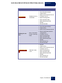
Optional Accessories
3000 Amp Flexible Current Clamp
Ordering information
(part name)
Loop length
Measurement range
Linearity
Operating temperature
Cable length
SOA-9045-3001
80cm
Up to 14000A AC
< 0.3%
-20°C to + 60°C
2M
300 Amp Flexible Current Clamp
Ordering information (part name)
Loop length
Measurement range
Linearity
Operating temperature
Cable length
SOA-9045-3000
45cm
Up to 1400A AC
< 0.3%
- 20°C to + 60°C
2M
Mini Clamp – 1 to 6 Amp
Ordering information
(part name)
A “hole” dimensions
Measurement range
SOA-0130-0100
10mm Max
Up to 6A AC (1A
nominal)
Operating temperature
- 20°C to + 60°C
Cable length
1.2M
Elspec | The Hardware
11
G4500 BLACKBOX PORTABLE OPERATIONAL MANUAL
August 2010
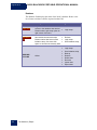
Mini Clamp – 100 Amp
Ordering information
(part name)
A “hole” dimensions
SOA-0180-5000
Operating temperature
10mm Max
Up to 100A AC
(100A nominal)
- 20°C to + 60°C
Cable length
1.2M
Measurement range
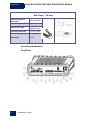
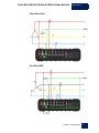
Controls and Indicators
Front Panel
12
The Hardware | Elspec
G4500 BLACKBOX PORTABLE OPERATIONAL MANUAL August 2010
Rear Panel
Elspec | The Hardware
13
G4500 BLACKBOX PORTABLE OPERATIONAL MANUAL
August 2010
Reference
#
For details refer to:
Description
1
Wi-Fi activity indicator
The Wi-Fi Access Point on page 29
2
Wi-Fi antenna
The Wi-Fi Access Point on page 29
3
Auxiliary power supply
socket
Auxiliary Power Supply on page 25
4
Digital Inputs socket
Digital Inputs on page 34
5
RS232 communication
socket
RS232 Interface on page 32
6
RS485/422 communication
socket
RS485/422 Interface” on page 32
7
WAN – 10/100Mb RJ45
Ethernet socket
Ethernet Ports View on page 28
8
LAN1 – 10/100Mb RJ45
Ethernet socket
Ethernet Ports View on page 28
9
LAN2/LCD – 10/100Mb
RJ45 Ethernet socket
Ethernet Ports View on page 28
10
PCMCIA Extension slot
TBD
11
Battery status indicator
Battery Status Indicator” on page 25
12
Operational status indicator
Operational Status Indicator on page 26
13
External temperature
sensor socket
Temperature Sensor on page 34
14
Reset to “factory defaults”
button
15
Operation ON/OFF switch
with indicator
Operation ON/OFF Switch’s Indicator on page 26
16
L1 voltage “presence”
indicator
Indication on page 17
17
L2 voltage “presence”
indicator
Indication on page 17
18
L3 voltage “presence”
indicator
Indication on page 17
19
I1/L1 current probe
detection indicator
AC Current Channels on page 18
14
The Hardware | Elspec
Reset Button on page 35
G4500 BLACKBOX PORTABLE OPERATIONAL MANUAL August 2010
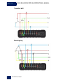
#
Description
For details refer to:
20
I2/L2 current probe detection indicator
AC Current Channels on page 18
21
I3/L3 current probe detection indicator
AC Current Channels on page 18
22
I4/Neutral current probe
detection indicator
AC Current Channels on page 18
23
Idc/Earth probe detection
indicator
Auxiliary AC/DC Current Channel on page 19
24
Vdc “presence” indicator
Auxiliary DC Voltage Channel on page 17
25
L1 voltage sensor socket
Voltage Inputs on page 16
26
Neutral voltage sensor
socket
Fast AC/DC Channels on page 16
27
L2 voltage sensor socket
Voltage Inputs on page 16
28
Earth/Ground reference
socket
Voltage Inputs on page 16
29
L3 voltage sensor socket
Voltage Inputs on page 16
30
I1/L1 current probe socket
AC Current Channels on page 18
31
I2/L2 current probe socket
AC Current Channels on page 18
32
I3/L3 current probe socket
AC Current Channels on page 18
33
I4/Neutral current probe
socket
AC Current Channels on page 18
34
Idc/Earth current probe
socket
Auxiliary AC/DC Current Channel on page 19
35
Vdc (minus) probe socket
Auxiliary DC Voltage Channel on page 17
36
Vdc (plus) probe socket
Auxiliary DC Voltage Channel on page 17
37
Main Power supply
ON/OFF Switch
Power Supply on page 24
38
Fuse holder
Power Supply on page 24
39
Main Power Supply inlet
socket
Power Supply on page 24
Elspec | The Hardware
15
August 2010
G4500 BLACKBOX PORTABLE OPERATIONAL MANUAL
Voltage Inputs
The BLACKBOX Portable provides 4 fast sampling AC/DC voltage inputs and
an auxiliary DC voltage input.
Fast AC/DC Channels
The fast sampling AC/DC channels are designed for AC network monitoring but
are suitable for DC voltage readings as well. The inputs are marked as L1, L2,
L3, and N with corresponded colors Red for L1, Yellow – L2, Blue – L3 and
Black for an N (Neutral).
All inputs are sensed/sampled simultaneously and continuously at 1024 samples
per cycle resolution using the Earth terminal (Green colored) as a reference. The
Phase (line to neutral) and Line (line to line) voltages are further calculated by a
digital signal processor unit at the same 1024 samples per cycle resolution.
Specifications
Maximum voltage
Maximum continuous
voltage
Maximum voltage
between channels
Input impedance (to
Earth terminal)
Input capacitance
Reference
16
The Hardware | Elspec
±8kV peak (to Earth terminal)
1kV (to Earth terminal)
10kV
>3 MΩ
< 20pF
Earth terminal
G4500 BLACKBOX PORTABLE OPERATIONAL MANUAL August 2010
Recording resolution
A/D resolution
PLL-Synchronized
source
PLL Lock Range
PLL frequency when
out of range
PLL sensitivity
Indication LEDs
5
1024 samples per cycle , continues
16Bit normal range + 16Bit extended range
The PLL synchronizes automatically to the best out of
L12 (between L1-L2 lines) and L3-G (between L3 to
earth) measurement channels
42.5 to 69Hz
55Hz
5% of nominal
10V AC
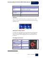
Indication
The L1, L2 and L3 voltage input channels are equipped with presence- indication LEDs. On voltage levels of above 10% of the nominal value the LED light
illuminates in blue.
Auxiliary DC Voltage Channel
The auxiliary DC voltage channel provides an additional and independent input
to the main AC/DC channel DC voltage readings. This is mainly suitable for a
voltage converter DC link side reading while the main voltage channels are on
the grid side.
DC Voltage Specifications
5
Maximum voltage
±1kV
Maximum continues
voltage
±1kV
Galvanic insulation
from the main AC/DC
voltage channels
3kV
Recording resolution
200mS
Defined by PLL frequency
Elspec | The Hardware
17
August 2010
G4500 BLACKBOX PORTABLE OPERATIONAL MANUAL
Indications (Vdc LED)
> ±20V (blue )
Current Inputs
The BLACKBOX Portable provides 4 AC and 1 AC/DC current measurement
channels/inputs.
AC Current Channels
The AC current Channels are marked as 1-4 (see picture above).
The inputs are designed to operate only with Elspec G4500 BLACKBOX compatible current probes. When the probe is connected and indentified, the corresponding LED illuminates in blue.
Maximum input
voltage
Recording resolution
Suitable probe
types
18
The Hardware | Elspec
5VDC
256 samples per cycle,
continuous
AC voltage output
probes
Rogowski flexible
probes
G4500 BLACKBOX PORTABLE OPERATIONAL MANUAL August 2010
Auxiliary AC/DC Current Channel
The Auxiliary AC/DC Current Channel is marked as Idc.
Maximum voltage
5VDC
Recording resolution
256 samples per cycle, continuous
Suitable probe types
AC/DC voltage output probes
Rogowski flexible probes
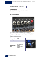
Power Type Diagrams
The G4500 BLACKBOX Portable is designed to serve in virtually any power
topology configuration. Below are some of the most popular power types with
suggested connection diagrams.
Single Phase with Neutral
Elspec | The Hardware
19
August 2010
G4500 BLACKBOX PORTABLE OPERATIONAL MANUAL
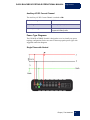
Single Phase without Neutral
Single Split Phase
20
The Hardware | Elspec
G4500 BLACKBOX PORTABLE OPERATIONAL MANUAL August 2010
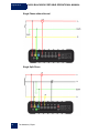
Three Wire Delta
Four Wire WYE
Elspec | The Hardware
21
August 2010
G4500 BLACKBOX PORTABLE OPERATIONAL MANUAL
Three Wire WYE
Delta High Leg
22
The Hardware | Elspec
G4500 BLACKBOX PORTABLE OPERATIONAL MANUAL August 2010
Delta Open Leg
Elspec | The Hardware
23
G4500 BLACKBOX PORTABLE OPERATIONAL MANUAL
August 2010
Power Supply
The BLACKBOX Portable can be powered by a main AC/DC or auxiliary DC
power supply. The auxiliary power supply can be used with the main power supply at the same time, providing better redundancy.
Main Power
When the Main Power Supply ON/OFF switch (refer to Rear Panel on page
13) is switched ON, the internal battery starts charging regardless of an Operation ON/OFF switch position.
.
100-240V AC ±10%, 50/60Hz
OR
120-370V DC
35 Watt maximum
2A/250V fuse holder
Allow only suitable fuse replacement!
24
The Hardware | Elspec
G4500 BLACKBOX PORTABLE OPERATIONAL MANUAL August 2010
Auxiliary Power Supply
48V DC
(35- 55V)
35 Watt maximum
No replaceable fuse protection!
Do not allow significant overvoltage!
The 48VDC power supply should be isolated from the
mains by double or reinforced insulation.
Status Indications
Battery Status Indicator
(Refer to: Front Panel on page 12)
Status
Flashing
blue
Solid blue
Red
State
Main or auxiliary power applied, Battery charging
Main or auxiliary power applied, Battery
fully charged
No main or auxiliary power available,
Powered by internal battery
Elspec | The Hardware
25
August 2010
G4500 BLACKBOX PORTABLE OPERATIONAL MANUAL
Operation ON/OFF Switch’s Indicator
(Refer to: Front Panel on page 12)
Status
State
Flashing blue
Booting or shutting down
Solid blue
Normal operation
Operational Status Indicator
(Refer to: Front Panel on page 12)
Status
Solid blue
Solid Red
Blinking
Blue
Blinking
Red
State
Normal operation, PQZip recording active
PQZip OFF / Flash Error / DSP Error / Error
in initialization
Initialization state
Communication Problem / Logger Problem /
Shutdown in process
Internal UPS
The BLACKBOX Portable contains an internal, uninterruptable power supply
module providing a short period of self-powered measurements sessions and/or
power supply interruptions ride-through.
The Internal UPS system contains a lithium battery for a up to 2 hours of fullyfunctioning operation and a super capacitors module allowing an additional 25
seconds of short interruptions ride-through even in the case of the main battery
being fully discharged.
The battery and super capacitors modules require no maintenance and are designed for a long service life. However, if the battery shows a significant decrease in performance, it should be replaced with a factory original. Consult with
your local Elspec agency for replacement battery ordering information. Please
refer to Replacing the Battery on page 142.
26
The Hardware | Elspec
G4500 BLACKBOX PORTABLE OPERATIONAL MANUAL August 2010
Grounding
The BLACKBOX Portable contains two independent ground systems:
Measurement ground: The reference ground for a measured electrical system
Safety ground: The line cord ground, same potential to all enclosure and connectorsrelated metal parts
The ground systems are internally isolated to avoid ground loops when externally they could be safely connected to the same or different ground systems.
Maximum permitted voltage between Safety and
Measurement grounds is 2kV DC or 1.5kV AC.
Elspec | The Hardware
27
August 2010
G4500 BLACKBOX PORTABLE OPERATIONAL MANUAL
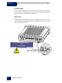
Networking
Ethernet Ports View
The above figure shows the factory default setting for the internal LAN and its
default IP addresses for external use.
28
The Hardware | Elspec
G4500 BLACKBOX PORTABLE OPERATIONAL MANUAL August 2010
The BLACKBOX Portable has 3 fast Ethernet link 10/100Mb ports in addition to the wireless access point:
Wide Area Network (WAN): Designed to connect the device’s internal LAN with
other types of networks. The most useful usage scenario would be connecting to the external Broadband router such as ADSL, Cable or Cellular for global, over Internet accessibility.
LAN1: The main Ethernet port with DHCP server configured as active. This port is the
main choice for a standalone PC or Laptop connection with the unit.
LAN2/LCD: Direct connection port to the BLACKBOX device, bypassing the internal
router. This port is mainly suitable for connecting the unit with a local LAN of computers.
The Wi-Fi Access Point
The BLACKBOX Portable contains an integrated IEEE 802.11g/b router preconfigured as an industry standard access point. This is to provide the most convenient and simplest connectivity with the Mobile Analysis Lab or any other laptop or desktop Wi-Fi-enabled PC.
The internal Wi-Fi Access Point is configured by the factory default as an unsecure network. The SSID name is configured as EG4500_[device serial number].
The [device serial number] is a unique string which allows for distinguishing
among several available devices. The device serial number is located on the
name plate as shown below.
Elspec | The Hardware
29
August 2010
G4500 BLACKBOX PORTABLE OPERATIONAL MANUAL
The Wi-Fi link is active when a Wi-Fi activity indicator light is flashing or
solid blue.
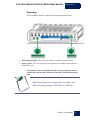
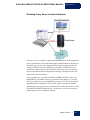
A Mobile Analysis Lab or a Single PC Connection
The most convenient way to connect a Mobile Analysis Lab or any other PC
is by using a Wi-Fi or wired Ethernet link. It is best to make only one connection type at time, and when a wired connection is used, disconnect or disable the wireless link.
Technically, any of the available Ethernet ports can be used for a single PC
connection. However, the most recommended is a LAN1 option (as shown
above) because of the integrated DHCP server available thru that port. When
connected, a PC will automatically obtain an IP address configuration which
allows a seamless connection to the BLACKBOX Portable’s internal
WEB/FTP servers as well as to a router management WEB server.
30
The Hardware | Elspec
G4500 BLACKBOX PORTABLE OPERATIONAL MANUAL August 2010
Office LAN Connection
When connected to an Office network, it most likely already employs a
DHCP server. Do not connect a BLACKBOX Portable to the office network
by LAN1 port, since an Office DHCP server operation could be interrupted
which could lead to severe network malfunctions.
Use only WAN or LAN2 ports connecting to DHCP active LANs
Serial Communication
The BLACKBOX Portable is equipped with 2 isolated Serial Communication interfaces.
Elspec | The Hardware
31
August 2010
G4500 BLACKBOX PORTABLE OPERATIONAL MANUAL
RS232 Interface
A standard DTE (Data Terminal Equipment) interface suitable for direct
communication with COM compatible interface, such as a standard PC serial
COM port
Description
Symbol Pin no.
Data Carrier Detect
Receive Data (Serial data input)
Transmit Data (Serial data output)
Data Terminal Ready.
Signal ground
Data ready state
Request to send
Clear to send
Ring Indicator
DCD
RDx
TDx
DTR
SG
DSR
RTS
CTS
RI
1
2
3
4
5
6
7
8
9
Specifications
Maximum cable length
Supported protocols
Duplex
Insulation
Suitable plug connector type
Default configuration
Up to 50 feet (15.2m)
TTY mode (HyperTerminal, Telnet emulation)
MODBUS RTU GPS
Full
2kV
Industry standard D-Type 9 pins, Female
Baud rate: 19200, Data bits:8 , Parity: None, Stop
Bits:1
RS485/422 Interface
A standard RS485 (full duplex) or RS422 (half duplex) interface
32
The Hardware | Elspec
G4500 BLACKBOX PORTABLE OPERATIONAL MANUAL August 2010
The connector pin description is shown below.
Specifications
Maximum cable length
Supported protocols
Duplex
Insulation
Suitable plug connector
type
Default configuration
Up to 500 feet (152m)
TTY mode (HyperTerminal,Telnet emulation)
MODBUS RTU
GPS
Half/Full
2kV
ENT-1004-0190
(supplied as default accessory, refer to page 8)
Baud rate: 19200
Data bits: 8
Parity: none
Stop bits: 1
Supported data rates
Wiring requirements
Termination
24AWG twisted pair
Shunt capacitance of 16pF per foot
Elspec | The Hardware
33
August 2010
G4500 BLACKBOX PORTABLE OPERATIONAL MANUAL
Temperature Sensor
The BLACKBOX Portable is equipped with an external connection terminal for
a 2-wire PT-100 temperature sensor. The PT100 is an industry standard thermocouple. Pt100 is also called an RTD element (Resistance Temperature Detector).
Suitable plug connector type
ENT-1002-0191
(supplied as default accessory,
refer to page 8)
Insulation
No insulation
Digital Inputs
The BLACKBOX Portable has 6 Digital Inputs for continuous recording.
Specifications
Maximum
voltage
Insulation
Sampling rate
Contact type
34
The Hardware | Elspec
50VDC
1kV
16 times per cycle (~1.25mSec at
50Hz, ~1mSec at 60Hz)
Dry contact
G4500 BLACKBOX PORTABLE OPERATIONAL MANUAL August 2010
Pin Description
Pin no.
Description
1
2
3
4
5
6
V
0
Digital Input IRIG B+
IRIG BDigital Input #1
Digital Input #2
Digital Input #3
Digital Input #4
+5V
Common
Reset Button
The Reset Button serves two main purposes:
Check LED operation.
Restore factory default settings.
To perform an action, the instrument should be powered ON and the Operational
Status Indicator should be solid blue or red.
The button can be accessed by a sharp instrument such as a small screwdriver
(as shown).
Elspec | The Hardware
35
August 2010
G4500 BLACKBOX PORTABLE OPERATIONAL MANUAL
Press and hold the reset button:
After 5 seconds – All LEDs turn on. At that stage you can check if all the LEDs
are okay.
After an additional 8 seconds-- The BLACKBOX Portable reboots and restarts
with the factory default settings.
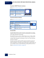
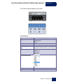
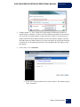
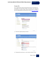
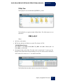
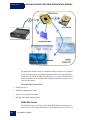
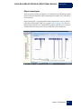
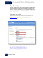
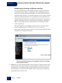
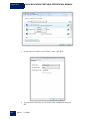
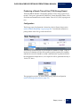
Wireless Router
1. To access the internal Wi-Fi router type http://192.168.1.254 on a Microsoft
Explorer address field.
A status WEB page appears:
The most simplified way to verify settings or configure the router is using the
Setup Wizard (marked in red above).
36
Wireless Router | Elspec
G4500 BLACKBOX PORTABLE OPERATIONAL MANUAL August 2010
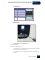
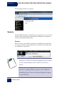
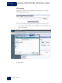
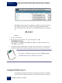
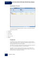
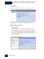
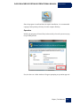
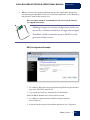
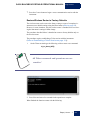
Factory Default Setup
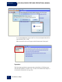
When initiated, the Setup Wizard begins with the above page.
2. To proceed with the setup procedure, press the next button.
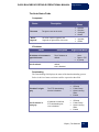
3. Define the mode of operation. (The default operation mode is Gateway).
Elspec | Wireless Router
37
August 2010
G4500 BLACKBOX PORTABLE OPERATIONAL MANUAL
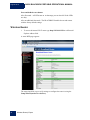
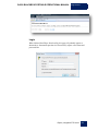
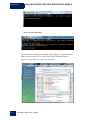
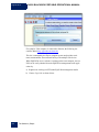
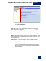
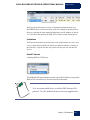
4. The second step is for the configuration of the automatic time synchronization option.
The default configuration for the router’s time synchronization is Disabled.
The time synchronization refers to the router’s internal time only. This setting has no influence on the
G4500 time synchronization. Refer to G4500 website
configuration for G4500 time synchronization options.
38
Wireless Router | Elspec
G4500 BLACKBOX PORTABLE OPERATIONAL MANUAL August 2010
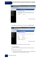
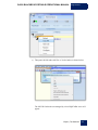
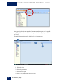
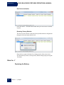
5. Specify the IP address and subnet mask for the router management interface,
then click Next.
The default configuration is 192.168.1.254 with 255.255.255.0 subnet mask.
Change the G4500 LAN1 configuration accordingly
when you modify the default IP address for the router.
Refer to G4500 website configuration for details.
Elspec | Wireless Router
39
G4500 BLACKBOX PORTABLE OPERATIONAL MANUAL
August 2010
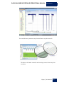
6. Set the WAN port operation type. The default setting is DHCP Client.
7. Configure the basic configuration of the Wireless interface.
The default settings are:
40
Band: 2.4Ghz (B+G), enabling both 802.11b and 802.11g interfaces
Mode: AP, (Access point)
SSID: EG4500_[serial number]. Define what name string (SSID string)
will appear on a list of wireless networks available.
Wireless Router | Elspec
G4500 BLACKBOX PORTABLE OPERATIONAL MANUAL August 2010
Channel number: 11. The 2.4 GHz Wi-Fi signal range is divided into a number of
smaller bands or "channels," similar to television channels. But unlike television channels, some Wi-Fi channel numbers overlap each other. Channel 1 uses the lowest frequency band and each subsequent channel increases the frequency slightly. Therefore,
the further apart two channel numbers are, the less the degree of overlap and likelihood
of interference. If encountering interference with a neighbor's WLAN, change to a distant channel.
Enable Mac clone: Disabled
8. Select your security method for the wireless interface. The default setting is:
None– unsecured.
Elspec | Wireless Router
41
August 2010
G4500 BLACKBOX PORTABLE OPERATIONAL MANUAL
When complete the final screen appears.
Website
The BLACKBOX Portable’s internal Website is designed to serve as a main user
interface with the instrument, providing enhanced management, configuration
and real-time monitoring functionality.
Access
When a wired or wireless Ethernet connection is established, the internal Website can be accessed by simply typing the device IP address in the address field
on a WEB browser application.
The Website is optimized to work with Microsoft©
Explorer 7. Other web browser applications can limit some functionality and/or show an incorrect
layout.
For local networking the browser should be configured as working without a proxy server. Refer to
Disabling Proxy Server in Internet Explorer chapter
for instructions.
42
Website | Elspec
G4500 BLACKBOX PORTABLE OPERATIONAL MANUAL August 2010
When the device IP address is unknown, use the Elspec Search utility to discover
it. (Refer to page 108)
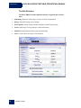
Login Page
The first page to appear is a Login Page.
Choose the interface language. The supported languages are:
English (Default)
Russian
German
Spanish
(For other languages – please contact your local Elspec distributor.)
The Password field defines user level/privileges. Two user levels are supported:
User
level
Password
Viewer
123
Admin
12345
Role
Read only, can choose interface language only, no
operations related changes are allowed
Administration, setup and full control
Elspec | Website
43
August 2010
G4500 BLACKBOX PORTABLE OPERATIONAL MANUAL
The passwords above are factory default values. You are advised to modify
Admin password if extended security measures are required.
Low Bandwidth
If you have low bandwidth access, it is possible to reduce the site’s complexity
by using fewer graphics, images and other data.
To activate a graphics-free interface, press the Low Bandwidth button as shown
above.
A graphics-free interface appears. To deactivate the feature, press High Bandwidth.
System Limitations
44
Website | Elspec
G4500 BLACKBOX PORTABLE OPERATIONAL MANUAL August 2010
The BLACKBOX Portable’s integrated Web Server is designed to support a
maximum of 3 concurrent user interface connections. However, the Admin level
can be logged in only one at a time. In the event that a new Admin connection is
established (a user has successfully logged in with Admin password), the previous Admin connection will be automatically logged off. Also, any Admin connection which is idle for more than 5 minutes will be automatically logged off.
Elspec | Website
45
August 2010
G4500 BLACKBOX PORTABLE OPERATIONAL MANUAL
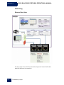
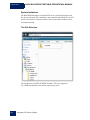
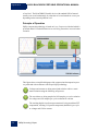
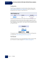
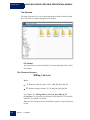
The Site Structure
The BLACKBOX Portable embedded website is organized into 6 subsections:
46
Monitoring: Real time monitoring of a variety of electrical parameters
Energy: Integrated energy meter readings
Power Quality: Power Quality standard compliance monitoring and setup
Service: Main entry for setup and device status monitoring
Multi-IO: Integrated digital inputs setup and monitoring
LCD: A virtual, black and white LCD emulation
Website | Elspec
G4500 BLACKBOX PORTABLE OPERATIONAL MANUAL August 2010
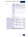
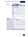
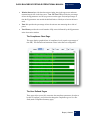
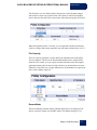
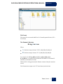
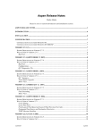
Monitoring Section
The Monitoring section contains the following pages:
Summary
Frequency
Average Voltage and Currents
Total Power Factor
Phase Order
Synchronization status
Elspec | Website
47
August 2010
G4500 BLACKBOX PORTABLE OPERATIONAL MANUAL
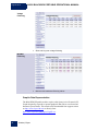
Voltage/
Current
48
Website | Elspec
RMS Voltages and Currents per phase
Unbalance, Positive and Negative Sequences
DC Voltage and Current channels readings
G4500 BLACKBOX PORTABLE OPERATIONAL MANUAL August 2010
Power
Active Power
Reactive Power
Apparent Power
True and Displacement Power Factor
Internal and External Temperature readings
Temperature
Elspec | Website
49
August 2010
G4500 BLACKBOX PORTABLE OPERATIONAL MANUAL
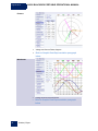
Phasors
Voltage and Current Phase diagram
Refer to Graphic Data Representation paragraph
below
Voltage and Current waveforms
Refer to Graphic Data Representation paragraph
below
Waveforms
50
Website | Elspec
G4500 BLACKBOX PORTABLE OPERATIONAL MANUAL August 2010
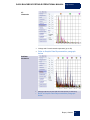
V/I
Harmonics
Voltage and Current harmonics spectrum (up to 40)
Refer to Graphic Data Representation paragraph
below
Voltage and Current sub and inter harmonics (in 5Hz bins)
Refer to Graphic Data Representation paragraph
below
Sub/Inter
harmonics
Elspec | Website
51
August 2010
G4500 BLACKBOX PORTABLE OPERATIONAL MANUAL
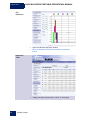
P/Q
Harmonics
Active and Reactive Harmonic powers
Refer to Graphic Data Representation paragraph
below
Voltage and Current harmonics in values, % and angles
Harmonics
Table
52
Website | Elspec
G4500 BLACKBOX PORTABLE OPERATIONAL MANUAL August 2010
V/I Min/Max
Harmonics
Minimum and maximum values and angels of Voltage and Current harmonics
Minimum and maximum values of Active and Reactive power
harmonics
P/Q Min/Max
Harmonics
Elspec | Website
53
G4500 BLACKBOX PORTABLE OPERATIONAL MANUAL
August 2010
Voltage
Flickering
Short and long term voltage flickering
Minimum and maximum flickering values
Min/Max
Flickering
Graphic Data Representation
The BLACKBOX Portable website requires a third party ActiveX control (PEGraph designed by Gigasoft) to present graphical data such as waveforms and
harmonic spectral charts. The control can be downloaded from support section
on http://www.elspec-ltd.com or directly from:
http://www.elspec.biz/g4kplugins/GigaPE.exe.
54
Website | Elspec
G4500 BLACKBOX PORTABLE OPERATIONAL MANUAL August 2010
Energy Section
Energy is defined as power consumed over time. In electrical distribution systems, the unit of time is one hour for all energy measurements and the kWh is
the basis for payment for buying and selling energy. This chapter focuses on the
flow of energy or power both within a system (active, reactive) as well as the
flow of power to and from the system to the grid (delivered or received). The
following are commonly used terms in describing energy flow within a system:
Active or Real: The portion of power flow that, averaged over a complete cycle of the
AC waveform, results in the net transfer of energy in one direction expressed as kWh.
Reactive /Volt Amperes Reactive (kVArh): Energy that flows back and forth with no
actual power flow. Reactive power flow transfers no net energy to the load and is sometimes referred to as wattless power.
Apparent: The combination of active and reactive energy (kVAh).
Power Factor: The ratio between real power and apparent power (a value between 0
and 1).
Consumption & Demand
Energy is produced and consumed within an electrical distribution system. Some
sites produce energy for the grid (Received Energy), others consume energy
from the grid (Delivered Energy), and still others both consume and produce energy for/from the grid. The Net Consumption is the difference between energy
that is used and produced. Therefore, a negative value for Net Consumption indicates that the site is producing more than it is consuming, or a received net
consumption.
Elspec | Website
55
August 2010
G4500 BLACKBOX PORTABLE OPERATIONAL MANUAL
The Consumption & Demand page is a quick look at some of the key components of the Detailed Info page. Here you find a cross-sectional summary view
of the amount and makeup (active or reactive) of the Net Energy (Received –
Delivered) produced/consumed by a site.
A Demand is an arbitrary measurement of power per configurable unit time using different averaging methods. A demand is measured in units of power even
though a time element does exist, while Peak Demand is the highest demand calculated since the last demand reset. Please refer to the ServicePower Setup
page for the
56
Website | Elspec
G4500 BLACKBOX PORTABLE OPERATIONAL MANUAL August 2010
Detailed Info
For a detailed breakdown of energy flow components, the Detailed Information
page presents all Active, Reactive, and Power Factor energy values
individually for both produced and consumed (Received or Delivered) energy.
Also shown below are the Net difference (Net Energy) as well as the sum total
(Total Energy) computations. The Total Energy computation contains the
combined figure for Active and Reacive Energy (Apparent Energy).
As previously stated, the summary page(Consumption & Demand) is extracted
from the details page. (see below) Note that the red and blue boxed areas areas
are consistent between the different page views. Please note that all values
may(not) be absolutely identical due to the delay in page views.
Elspec | Website
57
G4500 BLACKBOX PORTABLE OPERATIONAL MANUAL
August 2010
Measurement Status
The Measurement Status page provides additional statistical information and
necessary energy context information. The parameters and counters on this page
are actually set up in the ServicePower Setup section using the Configure
Energy & Demand button below.
An explanation of all Status Summary terms follows:
58
Started: This is the date and time stamp from the last energy reset
Last start: This is the date and time stamp for the last metering reset. Total consumption
is reset.
Up time: The total cumulative time the mechanism has been operational during the current period (since last start).
Down time: The total cumulative time the mechanism has not been operational during
the current period.
Availability: The percentage of time the system has been operational. This is important
because if this time exceeds a certain threshold, the data may not be considered reliable
Energy (Metering) interval: The energy interval is the size of the window used in
computing demand (e.g. 10 minutes).
External Sync: This function is currently fixed in disable mode.
Sliding window: Information regarding the demand averaging system in use:
Enabled: The demand is calculated using a sliding window averaging
system.
Disabled: The demand is calculated according to stationary time points.
Website | Elspec
G4500 BLACKBOX PORTABLE OPERATIONAL MANUAL August 2010
TDD
Total Demand Distortion – TDD – is the current distortion (harmonics above
the 1st) as a percent of maximum demand load. TDD is defined using the following relationship:
I h2
h2 I 2 *100%
L
ITDD=
Elspec | Website
59
August 2010
G4500 BLACKBOX PORTABLE OPERATIONAL MANUAL
Power Quality Section
The BLACKBOX Portable contains a power quality compliance engine that enables real-time evaluation of power quality according to standards such as
EN50160.
Power quality compliance or in short PQ Compliance is a set of electrically
measured parameters which are typically calculated based on some pre-defined
intervals or event triggers and are evaluated over a large observation window.
For most of the PQ parameters, the observation window is one week, which
means the displayed online information refers to the previous week. However,
using ELSPEC's PQSCADA and Investigator applications, all time intervals are
able to be observed.
A PQ parameter is typically based on a power quality event. For example the
DIP PQ parameter is based on counting DIP events over some observation period.
Different national standards vary in the way a specific PQ parameter is being
measured or observed. The PQ Engine also supports a user-customizable mode
in which all compliance parameters can be self-edited and modified by a user in
order to meet new conditions, rules, measuring intervals and even different observation periods.
The Power Quality section in the WEB interface is used to control and view
power quality measurement and compliance information computed by the PQ
Engine.
The Compliance Summary Page This page enables you to select the specific
compliance standard to be evaluated by the unit's internal compliance engine.
This page further contains on-line information and compliance status.
60
Website | Elspec
G4500 BLACKBOX PORTABLE OPERATIONAL MANUAL August 2010
Elspec | Website
61
August 2010
G4500 BLACKBOX PORTABLE OPERATIONAL MANUAL
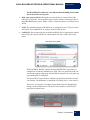
The Compliance Type sets the compliance standard.
In order to change or to activate a new compliance type:
1. If the PQ Engine is already running, set the Running Status to Stop, then
Click Apply changes.
Wait for the WEB page to refresh.
2. Select the desired compliance type, then change Running Status to Running.
3. Click Apply changes, then wait for the WEB page to refresh.
The new compliance type is now activated and running.
4. Verify that the Start Time field has changed.
Continuous compliance statistical information and events are stored in PQZIP
files. In addition, the Embedded Report field further indicates a type of report
that is auto-generated internally in the device's file system. Most compliance
types are not generating any specific report, and therefore, the report type will be
None. However, CREG type of compliance (used in Colombia) also autogenerates a specific format of report files as defined by the local regulator. The
report files can be found in the Integrated FTP Server on page 102.
The Evaluation Status field provides an overall status of PASS or FAIL of the
entire compliance. Anytime the evaluation period is not complete (typically it is
required 1 week observation), the status will be N/A (Not Available).
The Start Time field shows the last time the compliance engine was restarted.
The entire state and observation window history is stored on the internal nonvolatile memory, so even after powering down, the Engine will continue its
evaluation and maintain all indications. (Start time remains unchanged after device powered up.)
The Window Time On/Off fields specify how much aggregated time is already
in the observation window. ON refers to the aggregated window time the device
was powered on and OFF refers to the amount of window time the device power
was off. The format presented is [Days: Hours: Minutes: Seconds]. Ideally the
OFF time is all zeroes and the ON time is 7 days (which is the typical full observation period in most of the compliance types). Once the observation window
reaches 7 days, it will start to slide in steps of 2 hours. Sliding means the information from the oldest 2 hours is being dropped, where a new up-to-date 2-hour
interval is being stored.
The Measurement Flag field indicates whether the compliance evaluation is
currently Masked (equals Flagged) or not. Flagged time means a power quality
event such as DIP/SWELL or INTERRUPTION.
62
Website | Elspec
G4500 BLACKBOX PORTABLE OPERATIONAL MANUAL August 2010
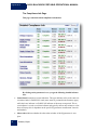
The Status Table shows a high level PASS or FAIL indication of each PQ parameter. Any PQ parameter that has an incomplete observation period will be
presented as N/A (Not Available). Additional information of how a PQ parameter is being evaluated can be seen by simply clicking on the parameter's text. For
example, clicking on the Voltage Frequency parameter within the EN50160
compliance mode will show an info page as shown on the figure below.
Elspec | Website
63
August 2010
G4500 BLACKBOX PORTABLE OPERATIONAL MANUAL
The Compliance Info Page
This page contains detailed compliance information.
By clicking on the parameter's text, you get the following detailed information:
64
Status/Partial contains two status indicators. The upper indicator refers to the entire observation window’s PASS/FAIL result (same status as presented in the Summary page),
while the lower indicator is a PASS/FAIL indicator of the most recent period. This recent indicator is served as real-time indicator and typically reflects only minutes to a few
hours of history (this is dependent on the specific PQ parameter measurement' intervals
and method).
Observation indicates whether the observation window of the PQ parameter is complete.
Website | Elspec
G4500 BLACKBOX PORTABLE OPERATIONAL MANUAL August 2010
Window/Interval provides the observation window time in the upper area and measurement interval time in the lower area. Time OK/Time FAIL provides the percentage
of time the PQ parameter was OK (as green text on the upper area) and percentage of
time the PQ parameter was outside the defined limits or failed (as red text in the lower
area).
Time N/A provides the percentage of time the unit was not measuring due to lack of
power.
Total Events provides the overall number of PQ events influenced by the PQ parameter
in the observation window.
The Compliance Chart Page
This page displays graphical bars of compliance levels (equals to percentage of
time OK). The minimum and maximum values in the chart are configurable.
The User Defined Pages
These pages allow you to fully customize the compliance parameters. In order to
be able to configure, you first need to change the compliance type to User Defined (under Compliance Summary page).
Elspec | Website
65
August 2010
G4500 BLACKBOX PORTABLE OPERATIONAL MANUAL
Service Section
The Setup pages are used to configure the BLACKBOX Portable. Notice that in
order to setup any of the pages and parameters in the BLACKBOX Portable interface, there is a need to login as Administrator.
To verify Administrator login, you should notice the unlocked sign
right side of the page. A locked sign
allow configuration.
means Viewer level only and does not
(Refer to Login Page chapter on page 43)
66
Website | Elspec
at the
G4500 BLACKBOX PORTABLE OPERATIONAL MANUAL August 2010
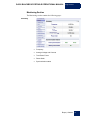
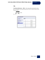
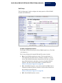
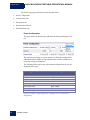
Unit Setup
The Unit Setup page is used to configure the main properties of BLACKBOX
Portable unit identification.
G4 Unit Configuration Section
The Product field specifies the type of BLACKBOX model in use. This field
is for future use.)
The Version field specifies internal HW and SW versions in which:
Boot: Specified Boot application version. The boot application is a
small separated part of the firmware. The Boot is stored on a secured
sector in the internal flash memory chip and is used for the very beginning of HW initialization and further execution of the BLACKBOX
firmware. The Boot executes either Bank A or Bank B firmware.
(Refer to Firmware Upgrade on page 88)
SW: BLACKBOX firmware version. Notice that BLACKBOX device
contains two banks of firmware, while the version in this field refers to
the currently executed firmware.
(Refer to Firmware Upgrade on page 88)
HW: BLACKBOX hardware version.
Elspec | Website
67
August 2010
68
G4500 BLACKBOX PORTABLE OPERATIONAL MANUAL
Website | Elspec
G4500 BLACKBOX PORTABLE OPERATIONAL MANUAL August 2010
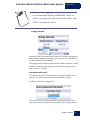
DSP: BLACKBOX DSP version. The BLACKBOX contains a dedicated DSP (Digital Signal Processing) module for high speed calculations. This field defines the firmware version of the code being executed
on this DSP.
The Site field enables the user to define a description of the site where
the device is installed. This site's description also appears in the ELSPEC Search utility under Unit Description when searching for devices.
For example:
The Description field is an additional text field for optional use.
The Operator field is an additional text field typically for inputting operator/technician name.
The Company field is additional text field typically for inputting company name.
Password Setup section
This section enables the Administrator to change or reset the passwords of
Viewer and Administrator levels. Notice that the default (Reset) passwords
are:
123: Viewer (can view but cannot configure)
12345: Administrator (can view as well as configure the device)
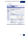
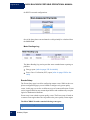
Time Setup
The Time Setup section is used to set and control the displayed time.
The RTC Counter refers to the counting of the internal battery backup
real time clock. The RTC starts its counting from the manufacture date.
RTC Counter format is: Days, Hours, Minutes, and Seconds.
Time Zone specifies the date and time to be presented on the WEB
(time and date are presented at the bottom of the page). The presented
time is the local time derived from the GMT time and the configured
Time Zone which shifts the GMT time backward or forward in accordance. (Greenwich Mean Time (GMT) means time at Greenwich, London . It is also referred to as UTC.)
Elspec | Website
69
G4500 BLACKBOX PORTABLE OPERATIONAL MANUAL
August 2010
Unit Date & Time allows you to set the current time and date manually.
Once you click on the configuration box, the date or time will instantly
appear and you can set it. Click on the Set Date & Time button and the
time is changed. However, if the unit's Time Synchronization module is
synchronizing with an external source (like NTP or GPS), the time will
be overridden as soon as the time is updated. To prevent automatic updates, set the Time Sync module on Self synchronization refer to Time
Synchronization on page 98.
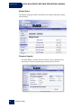
Network Setup
The BLACKBOX Portable provides 3 Fast Ethernet Links and a Wireless connection (Wi-Fi Access point and router).
The Network Setup page is used to configure all units' Network connection settings, except for the wireless access point which is an additional web interface.
Refer to Ethernet Ports View on page 28.
70
Website | Elspec
G4500 BLACKBOX PORTABLE OPERATIONAL MANUAL August 2010
Elspec | Website
71
G4500 BLACKBOX PORTABLE OPERATIONAL MANUAL
August 2010
LAN2/LCD Port Setup
This port is for direct connection to the BLACKBOX Portable device, bypassing its internal router (suitable for connecting the unit with local LAN of
computers/servers).
The Auto DHCP field is used to control the IP automatic setup method;
if set to enable, the unit gets its IP configuration from a DHCP server on
the LAN2 port side. If set to disable, the unit uses a fixed IP configuration on its LAN2 side as further defined.
The IP Address is used for setting the BLACKBOX Portable’s internet
address on LAN2 side.
The Subnet Mask is used for setting the BLACKBOX Portable’s subnet mask on LAN2 side.
Internal Link Port Setup
This port is an internal link between the BLACKBOX Portable’s internal
main CPU and the internal router. Ethernet Ports View on page 28.
The Auto DHCP field is used to control the IP automatic setup method;
if set to enable, the unit gets its IP configuration from the internal
BLACKBOX Wi-Fi router. If set to disable, the unit uses a fixed IP configuration on its Internal Link side as further defined.
The IP Address is used for setting the BLACKBOX Portable’s internet
address on Internal Link side.
The Subnet Mask is used for setting the BLACKBOX Portable’s subnet mask on Internal Link side.
Address Range Validation
Valid addresses range resulting from LAN2 pair of IP address and subnet
mask must be different than the address range resulting from the same pair
of settings on the Internal Link; otherwise, a connection failure is expected.
72
Website | Elspec
G4500 BLACKBOX PORTABLE OPERATIONAL MANUAL August 2010
Correct
Incorrect
LAN2 = 169.254… is different than
Internal Link = 192.168….
Ok, Different ranges.
LAN2 = 192.168… equals to
Internal Link = 192.168….
IP range conflict!!!
Gateway and SMTP
The Gateway is used for setting the BLACKBOX Portable’s default Gateway IP address. This address is used when the BLACKBOX Portable needs
to send data to IP addresses outside its LAN2 and Internal Link network
range. Typically this is set to the internal router.
The SMTP Server is used for setting an IP Address for Email Server to be
used for sending notification emails.
Ports Setup: This is a legacy option for remote access. Port Setup enables
changing the standard configuration of internet port numbers for standard
communication protocols (Emails, File Transfer, & Web browsing). This
might be used in networks where standard port numbers are forbidden or reserved by firewalls or in case one wishes to reserve the standard port number
for a legacy modem/router that does not support port forwarding. (Notice
that most external modems/routers on the market today do support port forwarding). It is suggested to leave the port numbers in their default setup so
that it will be straight forward for web browsers or FTP clients to access the
device via LAN/Internet.
The SMTP Port is used for setting port number of mail transfer.
The HTTP Port is used for setting port number of Web browsing.
Elspec | Website
73
G4500 BLACKBOX PORTABLE OPERATIONAL MANUAL
August 2010
The FTP Daemon is used for setting port number of File transfer (control channel).
The FTP Data is used for setting port number of File transfer (data
channel).
Notice that change of FTP ports also requires a
change in PQSCADA configuration.
Access Setup
This controls the FTP login and FTP password (FTP is File Transfer) for security measures. If no security measures are required, it is suggested to leave
the default settings for straightforward PQSCADA connection.
Notice that change of access setup also requires a
change in PQSCADA configuration.
Network Time
This section controls Time Synchronization.
Transport is used to set whether the Time Sync module selects the
source automatically or is manually forced to NTP or GPS source.
Main SNTP is used to configure the IP address of the Primary NTP
server to be used.
Alternate SNTP is used to configure the IP address of the secondary
NTP server to be used, in case the primary is not available.
(Refer to on page 98 for more information.)
74
Website | Elspec
G4500 BLACKBOX PORTABLE OPERATIONAL MANUAL August 2010
Power Setup
Elspec | Website
75
August 2010
G4500 BLACKBOX PORTABLE OPERATIONAL MANUAL
The Power Setup page contains the following subsections:
Power Configuration
Current probes info
Energy Intervals
Non-measured Current
Meter Readings Log
Power Configuration
This page defines the network type and nominal voltage and frequency values.
The network type settings are represented by five different configurations,
although the actual number of supported networks could be extended to virtually any existing configuration.
The following table proposes the recommended configurations for several
supported power types.
Power Type
Single Phase with Neutral
Single Phase without Neutral
Single split phase
Three Wire Delta
Four Wire WYE
Three Wire WYE
Delta High Leg
Delta Open Leg
Power Configuration to use
Single LN
Single LL
2Phase TR
Delta 3 wires
WYE 4 wires
WYE 4 wires
Delta 3 wires
Delta 3 wires
(Refer to Power Type Diagrams on page 19 for connection
diagrams.)
76
Website | Elspec
G4500 BLACKBOX PORTABLE OPERATIONAL MANUAL August 2010
Potential Transformer (PT)
Potential Transformer configuration is required only for a MV/HV networks
where the voltage is measured using PTs. When enabled, the Primary and
Secondary transformer values should be configured.
Nominals
The Nominals section defines the nominal values for frequency (F) and Voltages (V). The Frequency nominal affects compliance (refer to Power Quality Section on page 60) and the EN61000-4-30 measurement window. When
50Hz nominal is set, the window is 10 cycles, and for 60Hz, it is 12 cycles.
The Voltage Nominal also affects the compliance engine (refer to Power
Quality Section on page 60) and PQZip recording (refer to PQZip on
page 111).
For maximum logging resolution and efficiency it is
recommended keeping NOMINAL values as close to
the expected normal condition values and NOT to
maximum values!
Elspec | Website
77
August 2010
G4500 BLACKBOX PORTABLE OPERATIONAL MANUAL
Voltage Polarity
The Voltage Polarity settings allow for toggling the polarity without it being
necessary to change the wiring when voltage probes are connected in wrong
polarity due to a wiring mistake.
Current Probes Info
The Current Probes Info section provides the status and configuration for the
current probe detection mechanism. When it is successfully detected, the
probe type is displayed on the Info section. If no probe is connected/detected, the Info shows a No probe detected string.
Configuration options are directly dependent on the probe type, for example,
the mini clamp 1A/1V (refer to page 11 for specifications) is normally
used to measure a secondary current of a current transformer (CT). In that
case, the CT should be defined as Primary/Secondary values. On flexible
probe types, these settings are not available.
Nominal (A) value plays an important role for the PQZip recording functionality (refer to PQZip on page 111). In the event that the probe is
identified, the value is automatically set to probe default.
78
Website | Elspec
G4500 BLACKBOX PORTABLE OPERATIONAL MANUAL August 2010
For maximum logging resolution and efficiency it
is recommended keeping NOMINAL values as
close to the expected normal condition values and
NOT to maximum values!
Energy Intervals
The Energy Intervals section defines the interval of energy consumption information to be aggregated and stored. The same interval is applicable for
the Meter Reading Log (see below).
The aggregation for demand calculations can be further defined as a sliding
window by enabling a Sliding Window parameter. The sliding window’s
step is defined as 1 second.
Non-measured Current
The Non-measured Current section helps to configure calculated current
channels. The options are different for WYE and DELTA setups.
On WYE network type configurations:
The neutral current (In) could be optionally calculated from the sum of
three-phase currents, or alternatively, measured by the I4-current channel.
Elspec | Website
79
G4500 BLACKBOX PORTABLE OPERATIONAL MANUAL
August 2010
On DELTA network configurations:
One of the three-phase current channels could optionally be calculated from
the I1+I2+I3=0.
Meter Readings Log
The Meter Reading Log section provides some extended meter reporting capabilities:
Energy report (refer to page 159 for details)
Power Curve Verification (PVC) report (refer to page 154 for details)
Events Setup
The Events Setup page is used for configuring custom events. While in the compliance configuration pages you are limited to configure only power quality
events, in this page you are free to define any type of events notifications. Events
can be triggered based on any measured parameters and conditioned by complex
logical or mathematical functions.
Events setup is not related to power quality events. The Events setup is based on
a custom events engine that works in parallel to the power quality events engine.
The BLACKBOX Portable contains following event types:
Type
System Events
80
Website | Elspec
Event Code range
1-200
G4500 BLACKBOX PORTABLE OPERATIONAL MANUAL August 2010
User Custom Events Setup
Power Quality and Compliance Events
Reserved for other/future usage
201-232
233-300
301...
All events triggered in the BLACKBOX Portable are stored in the logger (flash
memory) which is viewable through the System Log page.
In addition, all events are also stored in the PQZIP files and can be further analyzed in the ELSPEC PQSCADA/Investigator software.
Events can generate an email-notification (refer to E-mails Alerts page for more
information).
Codes 201 – 232 are used for configuring up to 32 different, fully customized
events.
A custom event is typically built from one or more logical/mathematical conditions. When the conditions are met, the event is triggered and the following information is generated and stored:
Time Stamp of beginning
Event Code number
Duration of event
Magnitude (A parameter value recorded during the event)
Magnitude deviation (from the normal/configured value/treshold)
Phases that were influenced
Severity of the Event ( value indicating how severe ithe event is)
Although the information implies a power related event, you are free to
configure other type of events that are not related to specific power network
parameters, such as digital input-based events or even temperature-based events
and so on. (In such cases the Phases involved information should be left
blank/ignored.)
Events can also be based on multiple conditions, for example an event which is
triggered if both voltage is above some treshold and outside (PT-100) temprature
exceeds a certain limit.
Elspec | Website
81
G4500 BLACKBOX PORTABLE OPERATIONAL MANUAL
August 2010
The Events Setup Page
This page contains buttons for applying changes/creating/deleting and
performing various actions on selected events.
Events List
The Events List section shows the existing user events. There are few modes
to use. A user may create events manually or select an already prepared set
of events from the Preset list.
Preset 1, Preset 2…: An already prepared events configurations (hard
coded in the firmware). Preset 2 is very useful for DFR (Digital Fault
Recording) applications.
User Defined: Manual creation of events
Notice that changing between presets will erase the
content of what is already defined.
When selecting User Defined, you can create multiple events. Once an
event is created, it is added to the list.
Example:
82
Website | Elspec
G4500 BLACKBOX PORTABLE OPERATIONAL MANUAL August 2010
The check boxes at the left are used to select either all (if press on top) or a
selective event entry. On the selected events, you may select a specific
action from the Action on Selected Events list and then press the Apply
action button to perform the action.
The Counter shows the current count of events. The counter can be zeroed
by using the Reset Counter action.
Review the System Log to view the events online.
Creating a new User Defined Event
In order to create a new event, click on the button. The following section
appears:
Notice the underlined fields which can be clicked for
hints that provide online information about the field
and its usage.
The Description is used to set a meaningful name for the event.
Elspec | Website
83
G4500 BLACKBOX PORTABLE OPERATIONAL MANUAL
August 2010
The Code is the event code #. The code number is selected
automatically from the available user events codes.
An event is based on one or more conditions. There are two types of
conditions Single and Multiple. No matter what type of condition is
linked to the event, the link between an event and its dependent
condition/s is by a condition ID string as selected in the Condition
selection box. Use the Edit Condition button to create new or edit an
existing condition.
An event is basically a logic signal. Anytime a condition is not active,
the event remains in a "0" state. When a condition is met, the event
becomes "1" state (beginning of event). The event remains on "1" state
until the condition is de-activated (end of event). The trigger
configuration field defines what situations will generate an event record.
Notification is either on the beginning state, end state or at both states.
Notice that if selecting the beginning of an event, the
duration indication of the event will be recorded as
zero.
User events are stored automatically in the system log and PQZIP. In
addition, you may set the Notify by Email to create an email notification as
soon as the event is triggered.
The Save button is used to save the configuration.
The More button displays more advanced settings that you can control.
Creating Event's Conditions
84
The Single type of condition is defined as the result of some rule
(mathematical operation on some system parameters), For instance, a
percentage voltage drops below the threshold or a change of digital input
and so on. The condition has 2 logic states, Activated(1) and Deactivated(0). Transition to each state is fully user configurable.
A Multiple-type of condition is a combination of 2 other subconditions.
A Multiple-type condition must be linked to 2 subconditions, each of
Website | Elspec
G4500 BLACKBOX PORTABLE OPERATIONAL MANUAL August 2010
these 2 subconditions can be either Multiple or Single type. Therefore,
the Multiple- type condition can be used to create a complex hierarchy
of conditions.
Notice that until there are at least 2 conditions defined, it is impossible to create a Multiple condition.
The ID Condition is identified by a text ID. Two conditions cannot be
set to the same ID string.
The Type selects the type of condition (either Single or Multiple).
Single Type Condition
The Based on list box is used to select a group of parameters for further
user selection.
The Parameter list box is used to select the specific parameter from a
previously selected group. The selected parameter will be used as the
"X" variable in the condition rules (operation).
Elspec | Website
85
G4500 BLACKBOX PORTABLE OPERATIONAL MANUAL
August 2010
The Activation area is used to configure the rules that will be applied to
cause real-time activation of the condition (change from 0 -> 1). For example, if you set the following: Voltage RMS 1 (X = V1), Compare to is
set to the configured Nominal voltage (say, V = 230V), Deviation is set
10 (D = 10%) and Operation is set 100*(|X-V|/V) >= D, the condition
will be activated when the RMS voltage of channel 1 goes 10% above or
10% below nominal voltage.
The Deactivation area is used to configure the rules that will be applied
to cause real-time de-activation of the condition (change from 1 -> 0).
For example, if you set the following: Voltage RMS 1 (X = V1), Compare to is set to the configured Nominal voltage (say, V = 230V), Deviation is set 10 (D = 10%) and Operation is set 100*(|X-V|/V) < D, the
condition will be de-activated when the RMS voltage of channel 1 goes
below 10% deviation from nominal.
The Compare to list is used to select the type of reference value ("V")
to compare to the X parameter value.
The Parameter is for setting reference to system parameter such as
nominal voltage value.
User Value enables the user to edit his own reference value.
Interval average enables user to compare X to its averaged value over a
defined time interval.
Value ∆ enables dX/dt (time deviation) operation, which means X is
compared to its previous sample value. For instance, if the selected X
parameter is V1 RMS (from group 10[ms] Fast RMS than V = X[-1]
(meaning, previous 10ms RMS value).
Deviation defines the Deviation ("D") value used in the operation formula. Notice that some operations do not contain deviation; in such
cases the deviation configuration is not in use.
Operation defines the rule or mathematical operation to apply for Activation or Deactivation of condition.
Multiple Type Condition
86
Website | Elspec
G4500 BLACKBOX PORTABLE OPERATIONAL MANUAL August 2010
Condition A is used to select ID of first sub-condition.
Condition B is used to select ID of second sub-condition.
Logic is used to define the combined logic state between the two subconditions A and B.
Magnitude Combination instructs the events engine how to compute
the Magnitude resulting from a combined condition. For instance, say
condition A and condition B are both voltage parameters. In this case,
selecting Avg. (Average) or Max (Maximum) is practical. However if
condition A is voltage and condition B is current, then AVG or MAX is
irrelevant, while A-only option is more practical (meaning only magnitude of voltage from condition A will be taken).
Elspec | Website
87
August 2010
G4500 BLACKBOX PORTABLE OPERATIONAL MANUAL
Display Setup
The Display Setup page enables customization for regional and generic displayrelated settings.
Firmware Upgrade
The BLACKBOX’s internal software (firmware) can be upgraded on demand using a Firmware Upgrade page located on Service section.
88
Website | Elspec
G4500 BLACKBOX PORTABLE OPERATIONAL MANUAL August 2010
The firmware upgrade procedure requires Admin level privileges.
(Refer to Access on page 42.)
Firmware Banks
The BLACKBOX Portable implements a comprehensive firmware management mechanism designed to insure a failure-free field upgrading functionality. The mechanism insures that at any time there are two firmware images
available, where only one is active, which means running, another is available to be upgraded.
The firmware images are stored in a dedicated non-volatile flash memory
block referred to as Bank.
The Bank’s status is displayed on the Banks section on Firmware Upgrade
page.
Active Bank shows which firmware Bank is actually in use.
Bank A/B version displays a Bank’s firmware and condition. A numerical- only firmware name means valid firmware, which is ready to use. In
some situations the firmware could be further marked with a prefix character to identify a firmware status. The table below describes status prefixes available:
Prefix
Status
“*”
(Asterisk)
The firmware was upgraded and reboot is pending to activate the
image for the first time. The user is free to initiate reboot manually
to complete the upgrading procedure.
The firmware image failed to complete the initialization process
successfully. The firmware was declared as “Faulty”, another bank
is being used.
The firmware bank is being upgraded at the moment, wait for a
completion.
The bank is empty.
“F”
“+”
“E”
For example, if firmware 0.3.52.0 would be found faulty/damaged/corrupted
it will appear as F0.3.52.0 on the Bank A/B version field. In such a case it is
recommended to check if the firmware file is authentic and attempt to upgrade it again.
Elspec | Website
89
August 2010
90
G4500 BLACKBOX PORTABLE OPERATIONAL MANUAL
Website | Elspec
G4500 BLACKBOX PORTABLE OPERATIONAL MANUAL August 2010
Firmware File
New, complimentary firmware upgrades that can offer new and improved
functionalities are released often. Usually, new firmware can be expected to
be released every couple of months. The new firmware files are available in
the Service/Download section on the Elspec web site: http://elspec-ltd.com/.
a) Select Power Quality Analyzers Section.
b) Download the latest firmware version from the Software section.
Elspec | Website
91
August 2010
G4500 BLACKBOX PORTABLE OPERATIONAL MANUAL
HTTP Upgrade
Probably, the simplest way of upgrading your instrument is by using the
HTTP Upgrade functionality.
This can be initiated by using the Local Image Firmware Upload section.
a) Press the Browse button and select the image file you’ve downloaded on
your local computer.
b) Press Open.
92
Website | Elspec
G4500 BLACKBOX PORTABLE OPERATIONAL MANUAL August 2010
c) Press the Upload local firmware image button to initiate an actual upgrade process.
It is recommended using “simple” folders such as
c:\Temp for local firmware upgrades.
Folders which require a special security, such as “My
Documents” or “Desktop” may not operate correctly
with HTTP upload.
FTP Upgrade
An alternative option of upgrading your instrument is by using an FTP (File
Transfer Protocol) interface. The BLACKBOX Portable employs an FTP
client module which is capable of downloading a firmware image file from
an external FTP server automatically.
The FTP firmware upgrade functionality is configured in the FTP Firmware
Upgrade section. The factory default configuration settings define an ELSPEC corporate FTP server which is loaded with a latest released firmware.
Elspec | Website
93
August 2010
G4500 BLACKBOX PORTABLE OPERATIONAL MANUAL
Alternatively, any other FTP server could be used. We recommend Filezilla,
a free FTP server (http://filezilla-project.org/) or similar.
94
Website | Elspec
G4500 BLACKBOX PORTABLE OPERATIONAL MANUAL August 2010
FTP server
FTP username
FTP password
Firmware filename
The IP address of the external FTP server where the
firmware file is located. The default settings is:
212.143.246.204 which is the ELSPEC’s FTP server
which is loaded with a latest released firmware
The username to login to the FTP server. The default is
ELSPEC, as for Elspec’s FTP server
The password to login to the FTP server. The default is
elspecelspec, as for Elspec’s FTP server
The firmware filename. As default, the latest firmware
located under Elspec’s FTP server is G4k.bin
When ready, press Upgrade FW to initiate the upgrade process.
Elspec | Website
95
August 2010
G4500 BLACKBOX PORTABLE OPERATIONAL MANUAL
When, completed it appears as:
Multi-IO Section
The Multi-IO Section provides the status and configuration for the digital Inputs
and RS232 serial interface.
96
Website | Elspec
G4500 BLACKBOX PORTABLE OPERATIONAL MANUAL August 2010
LCD Section
The LCD Section main page emulates an optional B/W display interface.
Time Synchronization
The BLACKBOX Portable contains a Time Synchronization module. This
module maintains and tracks time that is being used by the entire BLACKBOX system and specifically by the PQZIP engine for storing compressed
waveforms in accurate time stamp.
The Time Sync module is a multi-time-source receiver and manager that utilizes a unique algorithm to select the optimal time source, to adjust time and
to compensate on various delays, jitters and other communication-related
distortions.
Elspec | Time Synchronization
97
G4500 BLACKBOX PORTABLE OPERATIONAL MANUAL
August 2010
The main purpose of synchronizing a BLACKBOX device is to be able to
analyze and compare among multiple devices via the ELSPEC PQSACADA/Investigator system, such as analyzing an event’s source or propagation
over multiple points across the power network.
The following time sources are supported:
Primary NTP Network Server
Alternative NTP Network Server
GPS Receiver
RTC (internal real-time clock)
Typically, the Time Sync module selects the time source automatically per
availability and quality of the existing time sources. However, the Time
Sync module can be configured to work manually and force a specific time
source (explained later in this section).
98
The NTP Network Server is an external server machine that provides
NTP Clients (such as a BLACKBOX or a PC) a time over IP network
using NTP standard protocol. Time Sync supports two NTP Servers.
The first is acting as primary, and the second is an alternative in case the
primary is not available. NTP server is identified by an Internet (IP) address. The BLACKBOX is basically acting as an NTP Client that initiates time requests towards NTP servers. However the BLACKBOX also
acts as an NTP time server, and therefore, it can respond and provide
time for other BLACKBOX units that are configured to its NTP server.
Synchronizing more than 5 BLACKBOX units to the same BLACKBOX is not recommended, as it may overload its server. Instead, use a
maximum of 5 BLACKBOX client units to request time from one
BLACKBOX server, and then direct up to 5 others to one of the previous 5, etc. NTP Time synchronization method is recommended anywhere there is a relatively good internet or intranet communication.
A GPS Receiver is a GPS unit that receives a satellite signal and therefore requires special installation with a sky view or transponder from a
GPS receiver with a sky view. A GPS unit provides location and time information via a serial port (typically RS232/RS485 communication port
to the BLACKBOX). The GPS option is for remote sites where internet/intranet communication is not an option or, alternatively, network
communication is poor.
The RTC is an internal peripheral in the BLACKBOX unit that serves
as a default time source when no other external source available. The
Time Synchronization | Elspec
G4500 BLACKBOX PORTABLE OPERATIONAL MANUAL August 2010
RTC is powered by a battery to maintain clock progress even when the
BLACKBOX device power is off.
The Time Sync module provides the BLACKBOX system with a
global time format called GMT or UTC. Using a global time approach
enables the BLACKBOX to synchronize measurements with other
BLACKBOXs located somewhere else around the globe. While the time
being recorded with PQZIP files is always GMT, the time shown on the
WEB interface is the local time (refer to Unit Time at the bottom of the
WEB page). The Local time is internally computed by the BLACKBOX
from the UTC obtained from the Time SYNC module plus the Time
Zone (which is the number of hours offset per specific country/area).
The Time Zone is configurable (under Service tab, Unit setup page, Time
Setup section).
The Time SYNC module also provides the source and the expected quality
of time in Synchronization Status. (Refer to Monitoring Section on
page 47)
In this example the Main refers to primary NTP Server, while the Good refers to a good quality of time synchronization (meaning that the
learned/estimated time is very close to the true GMT obtained from the external time source).
Displayed Time Sources:
Main: Primary NTP Server source is currently the active time source.
Alternate: Alternative NTP Server is currently the active time source.
GPS: GPS is currently the active time source.
Self: RTC is currently the active time source.
Displayed Time Synchronization Quality/Accuracy:
Perfect: Perfect time quality, expected less than 10 [microseconds] deviation from GMT
Elspec | Time Synchronization
99
G4500 BLACKBOX PORTABLE OPERATIONAL MANUAL
August 2010
100
Good: Good time quality, expected less than 100 [microseconds] deviation from GMT
Moderate: Moderate time quality, expected less than 10[millisecond]
deviation from GMT
Poor: Poor time quality, expected less than 1[Second] deviation from
GMT
No Time Synchronization: No external time source available/expected
more than 1 second deviation from GMT
Time Synchronization | Elspec
G4500 BLACKBOX PORTABLE OPERATIONAL MANUAL August 2010
Configuring the Time Sync Module
In order to configure the Time Synchronization module go to Service tab,
Network Setup page, The Network Time section.
Transport is used to set whether the Time Sync module selects the
source automatically or is manually forced to NTP or GPS source.
The Main SNTP is used to configure the IP address of Primary NTP
server to be used.
The Alternate SNTP is used to configure the IP address of secondary
NTP server to be used, in case primary is not available.
Using SNTP shows the current NTP server in use (Main, Alternate or Self if
no external NTP is used)
Slew Mode configures the type of time slewing (adjustment) approach to
be used by the Time Sync module to compensate for time deviations and
network communication jitters. The default and preferred mode is
Automatic. When set to automatic, the slewing factor is according to
time source communication quality and you may only view the auto selected slew factor and step time in the below fields.
You may further configure the slewing mode to manual and set the Slew
Factor and Step Time fields.
Slew Factor is a percentage value between 0 to 100%, defining how
much to correct time in percentage towards the new GMT learned from
time source. 100% means full correction, or a step towards the received
time as is, and 0% means no change at all.
Elspec | Time Synchronization
101
G4500 BLACKBOX PORTABLE OPERATIONAL MANUAL
August 2010
Step Time is time in seconds and defines the threshold value. Above
this value, the Time Sync module will simply step towards the new
learned GMT time.
Manual slew modes contain Master and Slave,-which are manual modes
with the same user control. The only difference is that the defaults are
automatically written in the WEB interface (SLEW Factor and Step
Time fields). While the Master values fit more to a situation of a
BLACKBOX receiving unstable time and acting as an NTP server that
further feeds other BLACKBOX with its learned time, Slave values fit a
situation of a BLACKBOX only acting as an NTP client without further
spreading time to other units.
Time Sync and PQZIP Time Stamping
Since the main purpose of the BLACKBOX Portable is to continuously record and measure channels for analysis, it is essential to maintain a very accurate UTC time stamp. A PQZIP file is built from time records; typically a
record represents several minutes. Each record contains a beginning and an
end UTC time stamp. Once the Time Sync module detects that time is continuously drifting beyond a few tenths of milliseconds, the slewing is not
enough to compensate for the drift. Instead, a time step/jump is made and the
corresponding PQZIP record is closed with the old time stamp while a new
record is opened with the new stepped time. Such cases may happen if the
time source (NTP Server/GPS) is unstable or when the communication link
with the NTP server is inconsistent.
Integrated FTP Server
FTP is a file transfer protocol for exchanging and manipulating files over
a TCP computer network. The BLACKBOX Portable uses an integrated FTP
server providing the most convenient computer network standard interface to the
generated PQZip files and auto generated reports. The PQSCADA software system makes use of the FTP server interface by automatically downloading PQZip
files.
One of the easiest ways to launch an FTP session, which allows the user to access the BLACKBOX Portable’s internal memory, is by using the Elspec Search
utility (refer to Launching WEB or FTP Session on page 141).
Another way is by typing ftp://[device ip address]/ in the Windows Internet Explorer or Windows Explorer address field.
102
Integrated FTP Server | Elspec
G4500 BLACKBOX PORTABLE OPERATIONAL MANUAL August 2010
Login
When initiated from Elspec Search utility, this page will probably appear as
shown above. On manual operation it will most likely require a user name and
password like:
Elspec | Integrated FTP Server
103
August 2010
G4500 BLACKBOX PORTABLE OPERATIONAL MANUAL
If so, type:
User name:
ELSPEC
Password:
elspecelspec
It is recommended to open the folder in Microsoft Explorer rather than Internet
Explorer, since the latter may have some issues related to file operations.
To switch from Internet Explorer to the Windows Explorer, press the Page button and select Open FTP Site in Windows Explorer.
This will probably require typing a password again:
104
Integrated FTP Server | Elspec
G4500 BLACKBOX PORTABLE OPERATIONAL MANUAL August 2010
It is recommended marking the Save password checkbox if you prefer skipping that procedure the next time.
Elspec | Integrated FTP Server
105
August 2010
G4500 BLACKBOX PORTABLE OPERATIONAL MANUAL
System limitations
The BLACKBOX Portable’s integrated FTP server is limited by design to handle up to 4 concurrent FTP connections. Any connection while another 4 are still
active will be denied. Connection which is idle for more than 2 minutes will be
closed automatically.
The File Structure
The root directory of the BLACKBOX Portable’s FTP server appears as
CF_UPMB which points to the main storage memory drive.
106
Integrated FTP Server | Elspec
G4500 BLACKBOX PORTABLE OPERATIONAL MANUAL August 2010
PQZip Files
The PQZip Files are located under PQZIPDATA_ folder
The PQZip files are organized under PQZip folders. The folder names are constructed as:
FER_A_B_C
Where:
A: Device serial number
B: The date and time the folder was created. The format is: YYYYMMDDHHmmSSmmm
where YYYY = Year, MM = Month, DD = Day, HH = hour, mm – Minutes, SS = seconds, mmm = milliseconds
C: Sequential index of the folder. The index value is started with “1” on the very first
PQZip session initialization and incrementing on every new folder creation. When the
value reaches 999 it resets to a “1” on with the next folder.
The PQZip folders normally contain no more than 50 PQZip files.
Elspec | Integrated FTP Server
107
August 2010
G4500 BLACKBOX PORTABLE OPERATIONAL MANUAL
The PQZip files can be further recognized by a “PQZip” or “PQ” file extensions.
The “PQZip” extension files are “closed” and ready for download while the
“PQ” means that the file is still in a process. The PQZip file names are organized
as:
EF_A_B_C
Where:
A: Device serial number
B: The date and time the folder was created. The format is: YYYYMMDDHHmmSSmmm
where YYYY = Year, MM = Month, DD = Day, HH = hour, mm – Minutes, SS = seconds, mmm = milliseconds
C: Sequential index inside the folder. The index value is started with “1” on the first file
created in the folder and increments sequentially with the next files in the same folder.
The Date and Time used to construct PQZip folder
and file names are in UTC time format!
Integrated TelNet server
Telecommunications Network (Telnet) is a text-only (non-GUI) user command
protocol terminal emulation program for TCP/IP networks such as the internet or
108
Integrated TelNet server | Elspec
G4500 BLACKBOX PORTABLE OPERATIONAL MANUAL August 2010
a LAN. A Telnet client is often used to connect to a Telnet server in order to diagnose problems without specialized client software. The BLACKBOX Portable
device comes enabled from the factory capable of being used as a Telnet server.
In much the same way that we can enter the device through the Web as a GUI interface or FTP to transfer files, Elspec supports the use of a Telnet connection in
order to perform specific high level administrative functions that are not accessible through other interfaces. In addition, the BLACKBOX Portable uses a Telnet
emulation interface over a RS232 port.
Telnet Client Application
The standard Telnet Client Application is available as part of a Windows operation system. The client can be accessed using a command line interface.
1.
Type cmd on a run/search field on windows Vista or Start>Run on Windows XP and press Enter.
2. On the command prompt type telnet and press Enter.
Elspec | Integrated TelNet server
109
August 2010
G4500 BLACKBOX PORTABLE OPERATIONAL MANUAL
In case of error like below:
The Telnet client is probably not installed on the computer. To enable/install it,
launch Programs and Features on the control Panel. Then, turn Windows
features on or off and select Telnet client on the list.
110
Integrated TelNet server | Elspec
G4500 BLACKBOX PORTABLE OPERATIONAL MANUAL August 2010
Establishing a Telnet Session
1. Type open [device IP] on the telnet command line.
The login line appears:
2. Use login name: ELSPEC (all cap letters)
3. And password: elspecelspec
When -> line appears, the telnet session is ready for use.
Telnet Commands
The Telnet interface could be useful mainly for an advanced operational procedures such as restoring wireless router factory defaults (refer to page 153).
All Telnet commands and operations
are case sensitive!
PQZip Recording
The BLACKBOX Portable utilizes a unique compression technology (referred as
PQZip) which enables continuous gap-less recording of all electrical parametersrelated data for a significant time duration without the need of event thresholds
Elspec | PQZip Recording
111
August 2010
G4500 BLACKBOX PORTABLE OPERATIONAL MANUAL
of any kind. The BLACKBOX Portable device with standard 8GB of internal
memory can record continuously for a duration of several months or even a year
depending on the network pollution level.
Principle of Operation
PQZip compression technology is based on Lossy Compression Method which is
protected under US Federal Patent Law as well as by patent laws in several other
countries.
This figure shows a simplified diagram of the compression/decompression process performed with accordance with Elspec PQZip technology.
Voltages and currents are being sensed and scaled to achieve a maximum resolution using the following A/D process.
The waveforms are being sampled at 1024 samples per cycle resolution
for voltages and 256 samples per cycle resolution for currents.
The resulting digital waveform representation is being passed thru FFT
computation, resulting 512 spectral components (harmonics) per cycle
or voltages and 128 for currents.
112
PQZip Recording | Elspec
G4500 BLACKBOX PORTABLE OPERATIONAL MANUAL August 2010
Every harmonic component is being analyzed and compressed individually. Zero value components are being skipped. No zero harmonic
components are being evaluated over time and only changes in a value
or angle are being recorded. The resulting data is being compressed
using industry known Lossless compression algorithms.
The compressed harmonic data is being organized in blocks of up to 5
minutes of concurrent cycles and being stored along with the measured
frequency of every cycle and reference time stamps into a PQZip file
residing on the onboard flash memory. The typical compression ratio
expected as a ratio between incoming data volume on block 3 and the
data being stored is 1000:1.
The PQZip files can be downloaded automatically or manually using
the integrated embedded FTP server to the Mobile Analysis Lab or any
other computer system for further storage and analysis.
The compressed data is then reorganized and optimized for fast access
while in a compressed state. The resulting data is stored in the SQL
database for long term storage.
When required, the data is decompressed, recovering a full harmonic
spectrum for each cycle along with the associated time stamps.
The spectral data can further be used to reconstruct any individual cycle’s waveform in the same resolution as at the input module (1) with
accurate time and cycle duration. Any possible electrical parameters
can be calculated based on the data by retrieving precise accuracy and
wave shape.
The waveform displayed by the Investigator application is reconstructed based on compressed spectral data of every concurrent network
cycle. In addition, virtually any electrical parameter can be calculated
based on that data and displayed at any resolution or time span.
Operation
The PQZip recording does not require any site-specific configurations. As default, all units leave the factory with PQZip recording being switched ON, and
the instrument will start recording all channels automatically even on the first
power on. The PQZip active state is further defined as a normal operation condition (refer to Operational Status Indicator on page 26).
Elspec | PQZip Recording
113
August 2010
G4500 BLACKBOX PORTABLE OPERATIONAL MANUAL
Configuration
The PQZip status and Configuration page is located under a service section on
integrated WEB server interface (refer to page 31)
Administrator-user privileges are required to perform any change in configuration (refer to Login Page on page 43).
When modification is requested and the logged-in user privileges (the login
password) are less than administrator, you will be prompted to perform a login
with the Administrator password to allow modification.
114
PQZip Recording | Elspec
G4500 BLACKBOX PORTABLE OPERATIONAL MANUAL August 2010
1. Type the Administrator password and press Login.
2. Press Apply changes again to complete the change action.
Enabling/disabling
To disable the recording operation, change state to Disabled and press the Apply
changes button.
FIFO Concept
PQZip files are maintained on a local flash memory in a FIFO (First In First Out)
concept. This means that the file storage operation never stops, and when mem-
Elspec | PQZip Recording
115
August 2010
G4500 BLACKBOX PORTABLE OPERATIONAL MANUAL
ory becomes full, the oldest files are deleted automatically to free required space
for the newest data.
Fixed Quality versus Fixed Ratio
The most important parameter defining the actual compression ratio, (which determines the amount of storage required and maximum time continuous data can
be stored) is a PQZip threshold value or Tolerance as it referred on the WEB
page.
The Tolerance defines what change in an individual harmonic would be defined
as significant enough to store and being reproduced afterwards. The tolerance
value is defined in percentage to the full scale or nominal reading for the specific
channel.
It is assumed that changes within 0.1% of nominal would have no importance in
further power quality investigation, and the values within that range are averaged
to store the representative value only. The basic and factory default tolerance
value is normally defined as 0.1%. However, on some sites/networks that value
can still be considered too tight, for example, a highly fluctuating load or voltage
lines.
It is most likely that a user would prefer increasing a tolerance value for currents
or voltages or even both in order to achieve better compression ratios on highly
polluted network locations. The BLACKBOX Portable provides the possibility
of automatic adjustment of the actual tolerance value presuming a compression
ratio defined as amount of data being stored per month.
That option is called Fixed Ratio. When selected, the user is requested to define
the amount of data to be stored per month (Monthly Ratio) in MB.
Usually, slight voltage spectral changes have higher importance than current
changes. Therefore, the amount of data which could be stored for voltages may
be determined as greater than for currents. The V/I Relation parameter defines
the relationship between the data (a part of the Monthly Ratio) reserved for voltage. If the voltage portion is larger than currents, the system will define a tighter
tolerance for voltages than for currents.
116
PQZip Recording | Elspec
G4500 BLACKBOX PORTABLE OPERATIONAL MANUAL August 2010
The alternative way is to define and fix the tolerance values for both voltages
and currents to some user preferred value. This option is called Fixed Quality
since in that case the data will be stored at the same tolerance/quality at all times.
When Fixed Quality mode is selected, you are requested to define the tolerance
value for voltages and currents separately were the factory default value is 0.1%.
File Capacity
The File Capacity parameter is used to define the maximum time each PQZip
file will comprise. The file can be downloaded and data can be analyzed only
when the file is closed, so if you expect to monitor the data on the Investigator
application shortly after the data is being collected, you should choose low time
durations. For all other cases, longer durations are recommended so compression
ratios can be slightly improved.
Record Mode
The Record Mode parameter defines whether PQZip files will comprise FULL
data or event time stamps only (LIGHT mode). The default setting is FULL.
Elspec | PQZip Recording
117
August 2010
118
G4500 BLACKBOX PORTABLE OPERATIONAL MANUAL
PQZip Recording | Elspec
G4500 BLACKBOX PORTABLE OPERATIONAL MANUAL August 2010
Record Type
Starting from PQSCADA version 3.0, the PQZip file structure and algorithm has
been improved to gain better compression and data accuracy. When PQSCADA
3.0 or higher version is used, it is recommended keeping a PQSCADA 3.x setting.
Erasing All PQZip Data
By pressing the Erase PQZip Data button it is possible to clean the memory
from the all files being recorded. This operation requires Administrator-level
privileges and prompts for confirmation to avoid unauthorized data deletion.
The Software
PQSCADA Suite
Elspec | The Software
119
August 2010
G4500 BLACKBOX PORTABLE OPERATIONAL MANUAL
The PQSCADA Software Suite is installed on a Mobile Analysis Lab computer
(or other laptop/computer) providing unparalleled data monitoring and analysis
functionality for the BLACKBOX Portable devices. For software installation instructions, please refer to the PQSCADA installation manual or contact your local Elspec distributor.
The PQSCADA software suite:
PQSCADA server
PQSCADA Management studio
Elspec Power Quality Investigator
MS SQL 2005/2008 database engine
PQSCADA Server
The PQSCADA server is the heart of the BLACKBOX data management and
analysis system. The main functionalities of the PQSCADA server are shown in
120
The Software | Elspec
G4500 BLACKBOX PORTABLE OPERATIONAL MANUAL August 2010
the figure above and further described below with corresponded numbering
marks:
Data collection (Downloading): The PQSCADA server system is responsible for collecting all continuous data (PQZip files) from a connected device automatically. When the device is connected (wired or
wirelessly) the PQSCADA server automatically checks for any new
data availability using an FTP6 communication protocol.
Placing new files into the Incoming data folder: All new PQZip files
found on a connected device are copied (the original files remain on
device) to a temporary location on a local hard drive “Incoming data
folder”.
Data processing and storage: The next stage is data processing, in
which the data is being organized for storage and quick access (Stage
1) and then a variety of electrical parameters are being calculated
(Stage 2) based on the raw PQZip data. The reorganized PQZip data, as
well as the calculated parameter statistics are being stored in a local
SQL database. The files which have been processed and successfully
inserted to the database are then removed from the Incoming folder
Networking: The PQSCADA server integrates a dedicated HTTP (default port 80) interface that communicates with the PQSCADA Management Studio (interactive management application) and the Elspec
Power Quality Investigator (data analysis application) running on either
the same or different machine.
PQSCADA Management Studio
The PQSCADA Management Studio is an interactive tool which provides full
control and monitoring of all of PQSCADA’s activities.
6
Refer to page 97 for more details
Elspec | The Software
121
G4500 BLACKBOX PORTABLE OPERATIONAL MANUAL
August 2010
Administration Console
The main PQSCADA Management Studio’s window is a hierarchical table/grid
with following columns:
Components
IP Address
Downloading
Data Processing
Database
Components
The PQSCADA suite is designed to operate and manage a virtually unlimited
number of BLACKBOX devices, both Portable and fixed. The physical device is
represented under the system by the term Node.
The NODE is the software component which represents data taken by a physical
device such as BLACKBOX Portable or a fixed G4k model.
The SITE is a software component which represents a group of Nodes. The
SERVER is the representation of the physical machine (Analysis lab) on which
the PQSCADA server application is installed.
122
The Software | Elspec
G4500 BLACKBOX PORTABLE OPERATIONAL MANUAL August 2010
The Node Status Fields
Component
Status
Right Click
Description
Menu
The name
The given name to the node
“Needs
Upgrade”
The node requires upgrade. Use
Upgrade on right mouse click menu.
Refresh
Rename
Configure
Delete
Refresh
Upgrade
Delete
IP Address
Status
Description
Right Click Menu
IP Address or host name in
hyperlink format
The IP Address is
defined.
"No IP defined"
No IP Address is
defined,
Link is disabled.
Open in Explorer
Open in FTP
IP Setup
IP Setup
Downloading
The Downloading field displays the status of the data downloading process.
Below is the list of status variations could be expected on that field.
Status
"Disabled" in light
gray
Description
Right Click Menu
The FTP downloading
service is disabled.
"No IP defined" in
light gray
IP address not defined.
FTP downloading service is disabled.
Schedule operation
IP Setup
Folders setup
Open incoming
folder
Enable
Schedule operation
IP Setup
Folders setup
Open incoming
folder
Enable
Elspec | The Software
123
August 2010
G4500 BLACKBOX PORTABLE OPERATIONAL MANUAL
Status
Error: link failure
Error: login failure
"Next attempt in XX
seconds"
"Checking for new
files…"
"XXX kB/sec" in
normal color
124
The Software | Elspec
Description
Right Click Menu
No communication
IP was set.
However, device is not
reachable.
Check physical con
nection.
No communication
IP was set. Login fail-
ure
Use IP Setup to veri-
fy/modify FTP user
name and/or pass
word.
Waiting for the next
communication at
tempt
Communication estab-
lished,
Checking for new files
Refresh
Force connection attempt
Schedule operation
IP Setup
Folders setup
Open in Explorer
Open in FTP
Open incoming folder
Disable
Refresh
Force connection attempt
Schedule operation
IP Setup
Folders setup
Open in Explorer
Open in FTP
Open incoming folder
Disable
Refresh
Schedule operation
IP Setup
Folders setup
Open in Explorer
Open in FTP
Open incoming folder
Disable
Refresh
Force connection attempt
Schedule operation
IP Setup
Folders setup
Open in Explorer
Open in FTP
Open incoming folder
Disable
Downloading new files
Refresh
Force connection attempt
Schedule operation
IP Setup
Folders setup
Open in Explorer
Open in FTP
Open incoming folder
Disable
G4500 BLACKBOX PORTABLE OPERATIONAL MANUAL August 2010
Status
Error: Incoming folder
full
Error: Disk full
Error: incoming folder
not found
Error: cannot write file
Description
Right Click Menu
PQZip folder is full due
to folder limitations.
Use Folders Setup to
modify the Incoming
folder quota or free
some disk space.
PQZip folder is full due
to disk space limita
tions.
The incoming direc
tory is missing.
Cannot write the
downloaded file to
disk
Refresh
Force connection attempt
Schedule operation
IP Setup
Folders setup
Open in Explorer
Open in FTP
Open incoming folder
Disable
Refresh
Force connection attempt
Schedule operation
IP Setup
Folders setup
Open in Explorer
Open in FTP
Open incoming folder
Disable
Refresh
Force connection attempt
Schedule operation
IP Setup
Folders setup
Open in Explorer
Open in FTP
Open incoming folder
Disable
Refresh
Force connection attempt
Schedule operation
IP Setup
Folders setup
Open in Explorer
Open in FTP
Open incoming folder
Disable
Elspec | The Software
125
August 2010
G4500 BLACKBOX PORTABLE OPERATIONAL MANUAL
Data Processing
The Data Processing field displays the status of the PQZip data processing
engine. Below is the list of status variations could be expected on that field.
Status
"Disabled" in light
gray color
126
Description
Right Click Menu
The service is
disabled.
Folders setup
Define 'time of interest' interval
Configure service
Open incoming folder
Open 'bad files' folder
Open data backup folder
Enable
Refresh
Force file parse attempt
Folders setup
Define 'time of interest' interval
Show/ modify data channels
configurations
Configure service
Open incoming folder
Open 'bad files' folder
Open data backup folder
Disable
Recalculate data
Refresh
Force file parse attempt
Folders setup
Define 'time of interest' interval
Show/ modify data channels
configurations
Configure service
Open incoming folder
Open 'bad files' folder
Open data backup folder
Disable
Recalculate data
"Processing stage 1
of 2"
Stage 1 (PQZip
parsing)
"Processing stage 2
of 2" in normal colors
Stage 2 (Recalculate summaries)
The Software | Elspec
G4500 BLACKBOX PORTABLE OPERATIONAL MANUAL August 2010
Status
Description
Database error
Database is full or
unavailable
"Waiting for new
data”
Idle, no new data
found in Incoming
folder
Bad files folder is
full
“Bad files” folder
is full.
Right Click Menu
Refresh
Force file parse attempt
Folders setup
Define 'time of interest' interval
Configure service
Open incoming folder
Open 'bad files' folder
Open data backup folder
Disable
Recalculate data
Refresh
Force file parse attempt
Folders setup
Define 'time of interest' interval
Show/ modify data channels
configurations
Configure service
Open incoming folder
Open 'bad files' folder
Open data backup folder
Disable
Show last day log
Recalculate data
Refresh
Folders setup
Define 'time of interest' interval
Configure service
Open incoming folder
Open 'bad files' folder
Open data backup folder
Disable
Show last day log
Recalculate data
Elspec | The Software
127
August 2010
G4500 BLACKBOX PORTABLE OPERATIONAL MANUAL
Database
The Database field displays the status of the Node’s database. Below is the
list of status variations could be expected on that field.
Status
Login Error
Database is
full
XXX MB /
YYY MB
128
The Software | Elspec
Description
Login Error. The administrative
access to the database was denied.
Please select Login setup option on
right mouse click menu.
Database is full. The database size
has reached its maximum state.
Please resolve that issue on Size
limitation setup, free more disk
space or truncate unnecessary data.
Online
Right Click Menu
Login setup
Refresh
Login setup
Size limitation setup
Refresh
Login setup
Size limitation setup
Backup
Restore
Delete data
Re-index
Import data
Export data
G4500 BLACKBOX PORTABLE OPERATIONAL MANUAL August 2010
Elspec Investigator
The Elspec Power Quality Investigator is an innovative tool which helps explore
electrical network anomalies and investigating power quality issues with mouseclick simplicity.
Elspec Investigator is a client application that communicates, receives, and displays data from the PQSCADA server system (refer to page 120). The communication performed uses a standard HTTP protocol (port 80), so it is firewall
friendly and can be easily used over local LAN and/or over the Internet.
Elspec | The Software
129
August 2010
G4500 BLACKBOX PORTABLE OPERATIONAL MANUAL
Getting Started
Initially, the Investigator application appears with a window as shown below.
The panel on the left titled Measurement Points appears blank. In order to start
working with the tool, you need to add a PQSCADA SITE to work with.
Adding a Measurement SITE
Automatic Scan
When the PQSCADA server application is running on the same machine,
such as in the Mobile Analysis Lab, the most convenient way of adding a
site is by automatically scanning for local sites functionality. This Scan Local sites procedure is available in the File menu. This tool makes use of UDP
broadcasting on port 885 in a similar manner as the Elspec Search utility
searches for G4k devices.
130
The Software | Elspec
G4500 BLACKBOX PORTABLE OPERATIONAL MANUAL August 2010
However, in some situations, the tool may fail to discover local sites, due to
some of the following reasons:
The local firewall prohibited UDP broadcasting.
The Elspec Search tool is running and making use already on UDP 885
port.
The local site is down or unreachable.
If the automatic scan procedure does not provide sufficient results, it is recommended adding the SITE manually as described below.
Adding a SITE Manually
a) To Add a SITE manually, choose Add Node or Site option from File
menu.
b) Type a full URL for the SITE.
Elspec | The Software
131
August 2010
G4500 BLACKBOX PORTABLE OPERATIONAL MANUAL
For example: if the computer is connected to Internet, the following site
could be added: http://pqscada.com/demosite
This site is managed by the Elspec computer system and provides continuous measurements from an actual facility with multiple G4k devices.
When PQSCADA server software is running on the same computer, the site
URL can be easily obtained from the PQSCADA management studio application by:
a) Right mouse clicking on SITE under PQSCADA management studio
b) Choose Copy Link as shown below.
132
The Software | Elspec
G4500 BLACKBOX PORTABLE OPERATIONAL MANUAL August 2010
c) Then paste the link under Add Site or Node window, as shown below:
The full URL link to the site managed by a local PQSCADA server will
appear.
Elspec | The Software
133
August 2010
G4500 BLACKBOX PORTABLE OPERATIONAL MANUAL
It is recommended that you press the Test Connection button before OK to
ensure that the URL is valid.
When successful, the site will appear on the Measurement Points panel.
Operation
The Investigator application can present the recorded data in 5 different ways.
The data representation is called a View. To start work with the data analysis, it
is necessary to choose the view type first.
134
The Software | Elspec
G4500 BLACKBOX PORTABLE OPERATIONAL MANUAL August 2010
The view types available are:
Trend View: An historic data representation where user-selected electrical parameters
are presented as a trend graph in a continuous time frame
Events View: A table of events captured/detected by the device according to the
“Power Quality compliance program”
(refer to
Power Quality Section on page 60)
Spectrum View: Useful for harmonic spectrum representation including voltages, current and power harmonics
Summary View: Displays summary information over a defined period of time, including maximum, minimum and true mathematical averages of any parameter over a time
span defined by the user
Trend Grid View: Similar to the trend view, but with a grid/table style display
The Multi-View Concept
The Elspec Investigator supports a multi-view operation, which means that
you can open and operate a number of views of any type simultaneously.
When a new view is created, it appears as a blank screen and is docked as a
tab in the working area.
Elspec | The Software
135
August 2010
G4500 BLACKBOX PORTABLE OPERATIONAL MANUAL
Any open view has its own number of parameters and time span, so it is possible
to display different data or different time spans simultaneously using a number
of views.
Generally, the operation can be simplified as a 4 stage process:
1. Select the view
2. Select the parameters
3. Select the time span
4. Press a query button and receive the data
136
The Software | Elspec
G4500 BLACKBOX PORTABLE OPERATIONAL MANUAL August 2010
You can add/remove parameters any time and choose any time intervals.
The data can be further zoomed in and out using a mouse from/to any time
resolution.
Elspec | The Software
137
August 2010
G4500 BLACKBOX PORTABLE OPERATIONAL MANUAL
Elspec Search Utility
The Elspec Search Utility is a small yet useful tool that allows searching and the
ability to determine BLACKBOX family device IP addresses sharing the same
local LAN. The Elspec Search makes use of UDP broadcasting, sending a please
respond message to all devices on the LAN and displaying the resultant list of all
devices responding to it.
Obtaining the Search Utility
Elspec Search is a small program which does not require installation and is
available free on the Support/Downloads section of Elspec WEB site
http://elspec-ltd.com
Alternatively, it can be downloaded directly from:
http://www.elspec.biz/ElspecG4k/ElspecSearch13.exe.
Or, found on the Elspec PQSCADA disk.
138
The Software | Elspec
G4500 BLACKBOX PORTABLE OPERATIONAL MANUAL August 2010
Since the program is small and does not require installation, it is recommended
copying it and operating it directly from the computer Desktop.
Operation
Initially, the program will most likely be detected by a firewall system as trying
to open UDP port 885.
If so, the above or similar window will appear prompting an operation approval.
Elspec | The Software
139
August 2010
G4500 BLACKBOX PORTABLE OPERATIONAL MANUAL
It is highly important to enable the operation on the
first run by pressing the “Unblock” button. Failure to
do so will permanently disable the operation without
any further notification.
Some organizations do not allow manual firewall configuration as a part of a corporate policy. Contact
your system administrator for assistance in opening
UDP port 885 when necessary.
When initiating a scan procedure, the utility appears as a grid displaying all
BLACKBOX devices found on the network.
Once open, the scan procedure can be manually prompted by using the
File>Refresh List menu as shown below.
As an alternative, the scan procedure can be configured to automatically refresh
each second. This can be done by setting the Mode>AutoRefresh to ON. The default state is OFF.
140
The Software | Elspec
G4500 BLACKBOX PORTABLE OPERATIONAL MANUAL August 2010
The Elspec Search list shows a variety of important information about every
BLACKBOX device found on network; most of it is helpful to identify devices.
However, probably the most important information is the IP Address of each device. This allows the initiation of WEB, FTP or Telnet session with the device.
Limitations
The Elspec Search utility can operate only as one single instance at a time, since
it uses a single and fixed UDP port. When more than one instance is running at
the same time – only the first one will operate correctly, the rest will show no
devices.
Useful Features
Launching WEB or FTP Session
The WEB and FTP hyperlink buttons on the right of the IP Address string launch
WEB or FTP sessions directly from the Elspec Search window.
It is recommended that you define MS Internet Explorer© 7 as the default internet browser application.
Elspec | The Software
141
G4500 BLACKBOX PORTABLE OPERATIONAL MANUAL
August 2010
New Device Indication
Every new device – one that wasn’t found on the previous refresh is marked
in green.
Restoring Factory Defaults
The device can be forced to restore the factory default network configuration
through a left mouse button double click.
Please allow a couple of minutes for a change to take effect as the device
will automatically reboot, restoring factory default settings upon pressing the
Yes button.
How to….?
Replacing the Battery
142
How to….? | Elspec
G4500 BLACKBOX PORTABLE OPERATIONAL MANUAL August 2010
The BLACKBOX Portable contains a lithium battery that will provide up to 2
hours of fully functional operation without an external AC/DC power source.
The battery requires no maintenance and is designed for long service life. However, if the battery shows a significant decrease in performance, it should be replaced with a factory original. Please consult with your local Elspec agency for
information on how to order a replacement battery. The following procedure
takes you step by step through the process of replacing the battery in the
BLACKBOX Portable device.
Before You Begin
We recommend that you have all of the following ready and available to complete the battery replacement process:
BLACKBOX Portable device
Replacement Battery
Phillips head screwdriver
Flat head screwdriver
Elspec | How to….?
143
August 2010
G4500 BLACKBOX PORTABLE OPERATIONAL MANUAL
Removing the Battery
Warning: We strongly recommend that you power down this
device and remove all connected power and
communication cables before commencing service.
1. Remove the Rubber Cover from the front side of the device.
2. Remove all screws from Front Bracket (6 flat, 2 Phillips).
3. Remove the Front Bracket with Antenna extended straight.
144
How to….? | Elspec
G4500 BLACKBOX PORTABLE OPERATIONAL MANUAL August 2010
4. Remove Battery Connector from the device terminal.
5. Remove Battery from the Carriage.
Elspec | How to….?
145
G4500 BLACKBOX PORTABLE OPERATIONAL MANUAL
August 2010
Installing the New Battery
1. Place new battery in carriage.
2. Re- connect plug connector from battery to device terminal inside the device
(make sure wires are tucked into the device cavity).
3. Replace Front Bracket and secure with screws.
4. Replace Rubber Cover.
5. Re-connect all Power and communication cables.
6. Power up to test connections.
Status
State
Flashing
blue
Main or auxiliary power applied/Battery
charging.
Solid blue
Red
146
How to….? | Elspec
Main or auxiliary power applied/Battery is
fully charged.
No main or auxiliary power available/Powered by internal battery.
G4500 BLACKBOX PORTABLE OPERATIONAL MANUAL August 2010
Disabling Proxy Server in Internet Explorer
A Proxy Server is a computer or application that functions as an intermediary between a web browser (such as Internet Explorer) and the Internet or Web Server.
Originally proxy servers were designed to help improve web performance by
storing a collection cache of frequently used web pages. With the advent of
much faster connection speeds to the Internet, proxy servers are now primarily
used in corporate networks to help improve security by filtering out some web
content and malicious software.
Using a web browser, you connect to the BLACKBOX Portable’s web server
through HTTP in much the same way you connect to the Internet. To view the
web server of the device or embedded router, access to TCP Port 80 is required.
Depending on the configuration of your LAN, (please consult your Network
Administrator), you may (not) have permissions set to allow direct access to Port
80 on the BLACKBOX Portable device. In such cases, it may be necessary to
disable the proxy server in Internet Explorer.
Elspec | How to….?
147
August 2010
G4500 BLACKBOX PORTABLE OPERATIONAL MANUAL
To disable the proxy server:
1. From the main IE main window, select ToolsInternet Options.
The Internet Options window appears.
2. Select ConnectionLAN settings.
The LAN Settings dialog box appears.
148
How to….? | Elspec
G4500 BLACKBOX PORTABLE OPERATIONAL MANUAL August 2010
Figure 1: LAN Settings
3. Uncheck all pick boxes.
4. Click OK.
5. Press F5 to refresh the browser window.
The Login screen appears.
Elspec | How to….?
149
August 2010
G4500 BLACKBOX PORTABLE OPERATIONAL MANUAL
Establishing a Security on Wireless Interface
As a factory default setting, a BLACKBOX Portable is supplied with an unsecured wireless (Wi-Fi) interface configuration. This is probably the most convenient way of getting starting and using the device for the first time. However,
in practical usage scenarios, it is most likely that some level of security would be
required to avoid unauthorized access to configuration screens and/or the data.
The BLACKBOX Portable utilizes an industry standard wireless router which is
capable of providing a full list of security measures required for establishing a
fully secure and reliable wireless communication even on the most securitysensitive applications.
The most simplified way of enabling a wireless security is using the wireless
router’s Setup Wizard (refer to Wireless Router on page 36).
Step 6 of the wizard allows setup of wireless security, turning ON WEP or WPA
encryption access and password control.
The main selection is between two most popular security key exchange
and encryption methods:
150
WEP is the one of the oldest and probably still most popular encryption scheme. Some
security experts used to believe that this security mechanism it relatively easy to crack,
or break into, so it is not the best form of security for the wireless network. The password is defined as a 10 characters HEX number, which is quite easy to remember/use,
yet probably easier to break as well.
How to….? | Elspec
G4500 BLACKBOX PORTABLE OPERATIONAL MANUAL August 2010
WPA is a latest wireless security technology that provides significantly stronger wireless data encryption than WEP. WPA uses a 64 character passphrase as a Pre-Shared key
and provides a much stronger security level.
WPA encryption scheme is recommended for all cases when the client device supports this scheme.
Making changes in security configuration while connected by a wireless interface is strongly discouraged.
Establish a LAN connection on port LAN1 to configure the wireless router.
WPA Configuration Example
1. To establish a WPA data encryption scheme using TKIP encryption technology, select WPA(TKIP) from the list
2. Type a desired security key, then press the Finished button.
The BLACKBOX Portable unit is now wirelessly secured.
3. To establish a connection from the Mobile Analysis Lab select
Start>Connect to
4. Select the interface from the list and then right mouse click > Properties
Elspec | How to….?
151
August 2010
G4500 BLACKBOX PORTABLE OPERATIONAL MANUAL
5. On the Properties window, select WPA-Personal , then TKIP.
6. Type the same security key as was used in router configuration and press
OK.
152
How to….? | Elspec
G4500 BLACKBOX PORTABLE OPERATIONAL MANUAL August 2010
7.
Press the Connect button to begin a secure communication session with the
instrument.
Restore Wireless Router to Factory Defaults
The wireless router can be reset to the factory setting as a part of a complete instrument reset to default settings using the Reset button (refer to page 35).
However, in some situations, only the wireless router is intended to be reset leaving the instrument’s settings without change.
The procedure described below is intended to restore to factory defaults only on
the wireless router.
The procedure requires establishing a Telnet session with the instrument.
(Refer to Establishing a Telnet Session on page 111).
1.
On the Telnet terminal type the following wireless router reset command:
IO_Int_Reset_Wifi()
All Telnet commands and operations are case
sensitive!
2. Press Enter and wait a few seconds for the operation to complete.
When finished the function returns with the following:
Elspec | How to….?
153
August 2010
G4500 BLACKBOX PORTABLE OPERATIONAL MANUAL
The wireless router is now reset to its factory default settings.
Simplified Power Curve Verification (PCV) Report
The Power Curve Verification (PCV) Report is typically required by the Wind
Turbine Power Performance Measurement procedure, defined per IEC 6140012-1 standard. The typical report requires a continuous statistical aggregation
and periodical recording the following for several electrical and wind related parameters:
mean value (Avg)
standard deviation (StDev)
maximum value (Max)
minimum value (Min)
The BLACKBOX Portable implements a special reporting feature that performs
required statistical analysis onboard, without a need of an external PC or post–
processing of data. This feature can be extremely helpful in assisting a final PCV
report preparation, as well as in some other non-wind related applications.
The parameters available by default are:
Total Active power (Avg, StDev, Min, Max)
Frequency (Avg, StDev, Min, Max)
Total Reactive power (Avg, StDev, Min, Max)
Please contact your local Elspec distributor if some additional parameters are required.
154
How to….? | Elspec
G4500 BLACKBOX PORTABLE OPERATIONAL MANUAL August 2010
Elspec | How to….?
155
August 2010
G4500 BLACKBOX PORTABLE OPERATIONAL MANUAL
Configuration
The PVC report Configuration is located in the Service/Power Setup section
(refer to Meter Readings Log on page 80). To enable this automatic reporting feature select Parameters on the Mode field.
The Duration field defines the way the output files should be recreated. 1/Day
selection on file duration will force the system to produce separate files each
day, and the time a new file should be created is defined on the Log restart field.
In the configuration example above, a new report file will be generated each day
at 12:00 (UTC time).
The aggregation period for the statistical analysis is defined in the Energy Interval configuration (refer to Energy Intervals on page 79).
The Outcome
The report Outcome file/s is/are created in the Reports folder on the main flash
drive. The files are available through an FTP interface on page 97).
156
How to….? | Elspec
G4500 BLACKBOX PORTABLE OPERATIONAL MANUAL August 2010
File Format
The report files are created in MS Excel’s Comma Separated Values (CSV)
File Format.
The filename's Structure
DL log A to B.csv
Where:
A : Start time stamp in format: YYYY_MM_DD_HH_MM_SS
B : End time stamp in format: YYYY_MM_DD_HH_MM_SS
For example: file “DL log 2009_02_18 13_10_00 to 2009_02_19
07_40_00.csv” is a report file was created at 18/02/2009 at 13:10:00 and finalized on 19/02/2009 at 07:40:00
While the file is being processed, the filename consists of only the start time
record.
The filename time stamps are in UTC time format (not local time).
Elspec | How to….?
157
August 2010
G4500 BLACKBOX PORTABLE OPERATIONAL MANUAL
The Internal Structure
Below is an example of a typical file generated.
The first two columns specify a time stamp in UTC and local area time of
the last data included in the statistical analysis presented by the row. The
start time for a record is, in actuality, the stop time for the previous record in
the file.
158
How to….? | Elspec
G4500 BLACKBOX PORTABLE OPERATIONAL MANUAL August 2010
Producing a Simple Time of Use (TOU) Energy Report
The BLACKBOX Portable is designed to produce a basic energy report file internally. The report is generated in a MS Excel Comma Separated Values (CSV)
file format and intended to be used for further Time of Use (TOU) report generation.
Configuration
The Energy report Configuration is located at a Service/Power Setup section
(refer to Meter Readings Log on page 80). To enable this automatic reporting feature select Energy on the Mode field.
The Duration field defines the way the output files should be created. 1/Day selection on file duration will force the system to produce separate files each day,
and the time a new file should be created is defined on the Log Restart field. In
the configuration example above, a new report file will be generated each day at
12:00 (UTC time).
The aggregation period is as defined as the Energy Interval configuration
(refer to Energy Intervals on page 79).
Elspec | How to….?
159
G4500 BLACKBOX PORTABLE OPERATIONAL MANUAL
August 2010
The Outcome
The report Outcome file/s is/are created in the Reports folder on the main flash
drive. The files are available through an FTP interface.
File Format
The report files are created in MS Excel’s Comma Separated Values (CSV)
File Format.
The Filename's Structure
MR log A to B.csv
Where:
A: Start time stamp in format: YYYY_MM_DD_HH_MM_SS
B: End time stamp in format: YYYY_MM_DD_HH_MM_SS
For example: file “MR log 2009_02_18 13_10_00 to 2009_02_19
07_40_00.csv” is a report file was created at 18/02/2009 at 13:10:00 and finalized on 19/02/2009 at 07:40:00
While the file is being processed, the filename consists of only the start time
record.
160
How to….? | Elspec
G4500 BLACKBOX PORTABLE OPERATIONAL MANUAL August 2010
The filename time stamps are in UTC time format.
The Internal Structure
Below is an example of the typical file generated.
The first two columns specify a time stamp in UTC and local area time of
the last data included in the energy aggregation presented by the row. The
start time for a record is, in actuality, the stop time of the previous record in
the file.
Available parameters are:
kWh In
kWh Out
kVAh In
kVArh In
kVArh Out
Elspec | How to….?
161
International
North America
Europe
Elspec Ltd.
Caesarea Industrial Park
POB 3019, 4 HaShoham St.
Zone 23, Israel 38900
Tel: +972 4 6272 470
Fax: +972 4 6272 465
e-mail: [email protected]
Elspec North America Inc.
500 West South Street
Freeport, IL 61032
U.S.A.
Tel: +1 815 266 4210
Fax: +1 815 266 8910
e-mail: [email protected]
Elspec Portugal Lda.
Zona Industrial - Fase 1
4900-231 Chafe - Viana do Castelo
Portugal
Tel: +351 258 351 920
Fax: +351 258 351 607
e-mail: [email protected]