1
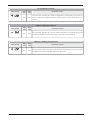
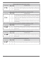
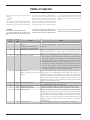
Table of alarms
The units have two types of malfunctioning
warning:
• pre-alarm
• alarm
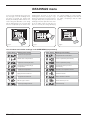
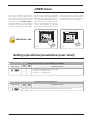
The first type is indicated by the flashing of the
red indicator light on the display; by pressing
the bell key, you can display the alarm list (with
index and cause shown in the table below). A
pre-alarm remains such for 60 seconds; if the
condition that caused it does not disappear
within this time, it becomes an alarm. The
alarms are visualised in the same way as the
pre-alarms, apart from the fact that the fixed
red indicator light comes on. Before resetting
the unit, you are advised to contact the After
Sales Assistance. To reset the unit you must
switch it off then on again, using the standby
button.
WARNING
The pre-alarms can become alarms if:
• a period of time equal to, or longer than,
60 seconds passes in the pre-alarm condition
• the maximum number of pre-alarms in an
hour (five) is exceeded. In this case, each subsequent pre-alarm will be visualised direct-
ly as an alarm, and as such will cause the
machine to stop until its cause is eliminated.
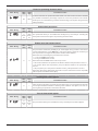
Pre-alarm
index
1
Alarm
index
101
2
102
3
103
4
104
5
105
6
7
8
106
107
108
9
109
EN - 26
Cause
Notes
Compressor thermomagnetic
switch
Fan thermomagnetic switch
Pump thermomagnetic switch
Fan thermomagnetic switch
This warning appears if the contact of the thermomagnetic switch
protecting the MTC (MTC = compressor thermomagnetic switch) is
opened.
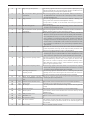
This warning appears if the contact of the thermomagnetic switch
protecting the MTV fan is opened. This code is displayed only if the
card is used as a replacement for cards with SW up to version 3.6.
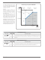
High pressure switch
This warning does NOT indicate the status of the high pressure
switch itself, but of the compressor contactor. The high pressure
switch acts directly on the compressor contactor. If the controller
controls the switch-on of the compressor, and the contactor is not
activated after 3 seconds, this signal appears. This alarm can also
be caused by a defect in the functioning of the transmission system
relay from the compressor contactor to the controller (indicated as
RAP in the wiring diagrams). If the contactor is deactivated while the
compressor is functioning, this warning reappears. AP.
This warning appears with the opening of the contact relating to the
Flow switch
Wat er dif fer ential pr essur e flow switch or to the differential pressure switch. This alarm is not
detected in the first 40 seconds from when the pump is switched on.
switch
The machine goes into lockout when the maximum number of flow
switch interventions allowed is exceeded. If frost protection mode
(and therefore the pump too) is activated in standby, the flow switch
status is also controlled. FL/PD.
Low pressure switch
This warning appears with the opening of the contact of the low pressure switch (intake on the compressor) BP.
No water inlet probe
This warning appears when the water inlet probe is disconnected.
No water outlet probe
This warning appears when the water outlet probe is disconnected.
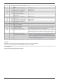
Water freeze
This warning appears when the frost protection temperature threshold (installer menu, parameter (6) default: 3°C) of the outlet water
is reached. The pre-alarm condition is removed when the outlet
water temperature exceeds the setpoint calculated by the controller
on the basis of an internal algorithm; the frost protection alarm is
suspended (in heat mode) for 3 seconds from when the compressor
is switched on.
No force probe
This warning appears when the force gas probe is not detected.