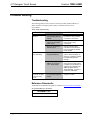
1
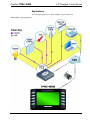
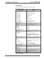
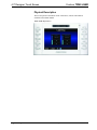
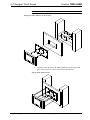
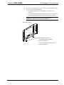
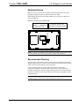
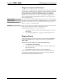
Crestron TPMC-4SMD 4.3” Designer Touch Screen Operations & Installation Guide Regulatory Compliance As of the date of manufacture, the TPMC-4SMD has been tested and found to comply with specifications for CE marking. Federal Communications Commission (FCC) Compliance Statement This device complies with part 15 of the FCC Rules. Operation is subject to the following conditions: (1) This device may not cause harmful interference and (2) this device must accept any interference received, including interference that may cause undesired operation. CAUTION: Changes or modifications not expressly approved by the manufacturer responsible for compliance could void the user’s authority to operate the equipment. NOTE: This equipment has been tested and found to comply with the limits for a Class B digital device, pursuant to part 15 of the FCC Rules. These limits are designed to provide reasonable protection against harmful interference in a residential installation. This equipment generates, uses and can radiate radio frequency energy and, if not installed and used in accordance with the instructions, may cause harmful interference to radio communications. However, there is no guarantee that interference will not occur in a particular installation. If this equipment does cause harmful interference to radio or television reception, which can be determined by turning the equipment off and on, the user is encouraged to try to correct the interference by one or more of the following measures: • Reorient or relocate the receiving antenna • Increase the separation between the equipment and receiver • Connect the equipment into an outlet on a circuit different from that to which the receiver is connected • Consult the dealer or an experienced radio/TV technician for help Industry Canada (IC) Compliance Statement CAN ICES-3(B)/NMB-3(B) Crestron product development software is licensed to Crestron dealers and Crestron Service Providers (CSPs) under a limited non-exclusive, non-transferable Software Development Tools License Agreement. Crestron product operating system software is licensed to Crestron dealers, CSPs, and end-users under a separate End-User License Agreement. Both of these Agreements can be found on the Crestron website at www.crestron.com/legal/software_license_agreement. The product warranty can be found at www.crestron.com/warranty. The specific patents that cover Crestron products are listed at patents.crestron.com. Crestron, the Crestron logo, Cresnet, Crestron Studio, Crestron Toolbox, Smart Graphics, SmartObject, SmartObjects, Smart Sizing, TouchPoint, and VT Pro-e are either trademarks or registered trademarks of Crestron Electronics, Inc. in the United States and/or other countries. Windows is either a trademark or registered trademark of Microsoft Corporation in the United States and/or other countries. Other trademarks, registered trademarks, and trade names may be used in this document to refer to either the entities claiming the marks and names or their products. Crestron disclaims any proprietary interest in the marks and names of others. Crestron is not responsible for errors in typography or photography. This document was written by the Technical Publications department at Crestron. ©2015 Crestron Electronics, Inc. Crestron TPMC-4SMD 4.3” Designer Touch Screen Contents 4.3” Designer Touch Screen: TPMC-4SMD 1 Introduction ............................................................................................................................... 1 Features and Functions ................................................................................................ 1 Applications................................................................................................................. 5 Specifications .............................................................................................................. 6 Physical Description .................................................................................................... 8 Setup ........................................................................................................................................ 11 Network Wiring ......................................................................................................... 11 Identity Code ............................................................................................................. 11 Configuring the Touch Screen ................................................................................... 11 Changing the Button Inserts ...................................................................................... 22 Installation ................................................................................................................. 23 Hardware Hookup ..................................................................................................... 27 Recommended Cleaning ............................................................................................ 27 Uploading and Upgrading ........................................................................................................ 28 Establishing Communication ..................................................................................... 28 Programs, Projects and Firmware .............................................................................. 29 Program Checks ........................................................................................................ 29 Problem Solving ...................................................................................................................... 30 Troubleshooting......................................................................................................... 30 Reference Documents ................................................................................................ 30 Further Inquiries ........................................................................................................ 31 Future Updates .......................................................................................................... 31 Operations & Installation Guide – DOC. 7027E Contents • i Crestron TPMC-4SMD 4.3” Designer Touch Screen 4.3” Designer Touch Screen: TPMC-4SMD Introduction With its clean, contoured appearance, the TPMC-4SMD Designer Touch Screen from Crestron® makes an elegant statement in any environment. Perfectly at home in the most contemporary residence or modern office building, its high tech good looks underline its power for simplifying everyday tasks and functions throughout any facility, all in a very affordable device that is versatile and easy to install. An incredibly thin profile and small footprint allow the TPMC-4SMD to be installed in places other touch screens just cannot go, providing the choice of mounting to a standard electrical box or to virtually any flat surface, even glass, granite or marble. A table top enclosure is also available, affording a very stylish, space saving solution for placement on a desktop or bedside table. Complete connectivity is provided through a single high-speed Ethernet connection, containing all control, video, intercom and power signals within a single wire. The TPMC-4SMD provides a customizable touch screen controller featuring Smart Graphics™, H.264 streaming video, audio feedback and 2-way IP intercom, cohesively merged into one seamless user interface. Additional features include white LED backlit buttons, a built-in proximity sensor, PoE (Power over Ethernet) network power and occupancy sensor inputs. Features and Functions • • • • • • • • • • • Modern, contoured appearance Thin profile and small footprint Affordable and easy to install 4.3” (~109 mm) widescreen active matrix color touch screen 800 x 480 WVGA display resolution Smart Graphics support High performance H.264 streaming video Crestron IP intercom Customizable audio feedback Built-in microphone and speaker Built-in proximity sensor (Continued on following page) Operations & Installation Guide – DOC. 7027E 4.3” Designer Touch Screen: TPMC-4SMD • 1 4.3” Designer Touch Screen Crestron TPMC-4SMD Features and Functions (Continued) • • • • • • • • 10 optional “hard key” push buttons White LED button backlighting and feedback Custom engravable button text Room occupancy sensor option* Single wire Ethernet connectivity PoE network powered Versatile wall, surface and tabletop mounting options Available with black or white smooth finish Advanced Touch Screen Control A Crestron touch screen offers an ideal user interface for controlling all the technology in a home, boardroom, classroom, courtroom or command center. Touch screens do away with piles of remote controls, cluttered wall switches and cryptic computer screens, simplifying and enhancing the technology. Crestron touch screens are fully customizable for controlling audio, video, lighting, shades, HVAC, security and other systems, with easy to use controls and icons, true feedback and real time status display, live streaming video and advanced navigation of digital media servers, tuners and other devices. Smart Graphics Crestron touch screens use Smart Graphics to deliver the ultimate user experience and the ultimate value, by enabling the creation of dynamically rich user interfaces with incredible efficiency and unparalleled functionality. Using Smart Graphics, programmers can swiftly integrate fluid gesture-driven controls, animated feedback, metadata, embedded apps and full-motion video for a deeply engaging and ultra-intuitive touch screen experience. Crestron Smart Graphics include the following enhancements: * • Cool looking graphical buttons, sliders, knobs and gauges are intuitive and fun to use. • Kinetic effects enhance the feeling of realism with lists and toolbars that scroll with momentum at the flick of a fingertip. • Drag and drop objects snap into place offering an easy way to switch sources. • Dashboard widgets personalize the touch screen with clocks, weather, news and other information. • Customizable themes allow a completely different look and feel for every user, event or season. • Fully developed SmartObjects™ enable sophisticated control over complex devices with minimal programming. SmartObjects are powerful Crestron-designed or custom-designed objects created in VT Pro-e® using Smart Graphics technology. Each SmartObject™ allows programmers to easily add controls, user presets, and metadata interfaces for everything from simple keypads to complex media devices and environmental systems. Item(s) sold separately. 2 • 4.3” Designer Touch Screen: TPMC-4SMD Operations & Installation Guide – DOC. 7027E Crestron TPMC-4SMD 4.3” Designer Touch Screen • Smart Graphics also includes the Smart Sizing™ feature, which allows the same user interface to be viewed on different size screens. White Backlit Buttons The TPMC-4SMD comes standard with 10 programmable “hard key” push buttons for quick access to commonly used functions. Each button features a translucent button cap with white LED backlighting. The backlighting is fully dimmable, either globally or separately for the left and right side. Alternately, each button LED can be programmed (via SIMPL Windows) to provide discrete feedback, affording clear indication of the status of each individual button. The TPMC-4SMD comes standard with its buttons pre-labeled for typical room control functions. Customized labeling can be attained using Crestron Engraver software. For a clean appearance, either column of buttons may be removed and covered using the no-button covers provided. Proximity Sensor The TPMC-4SMD senses as the user approaches it, waking its display automatically without having to touch the screen so it is always ready for use. Streaming Video High performance streaming video capability makes it possible to view security cameras and other video sources over the network right on the touch screen. Native support for H.264 and MJPEG formats allows the TPMC-4SMD to display live video images from IP cameras and servers such as the Crestron CEN-NVS200 Network Video Streamer (sold separately). IP Intercom Built-in IP intercom capability facilitates direct touch screen to touch screen intercom and monitoring right over the LAN without requiring any additional AV wiring. The TPMC-4SMD features an integrated microphone and speaker for clear speech communication. Audio Feedback Customized audio files can be loaded on the TPMC-4SMD to add another dimension to its touch screen graphics using personalized sounds, button feedback and voice prompts. Single Wire Connectivity A simple Ethernet LAN connection is all that is required to wire the TPMC-4SMD, containing all control, video, intercom and power signals in a single wire. Power over Ethernet Using PoE technology, the TPMC-4SMD gets its operating power right through the LAN wiring. PoE eliminates the need for a local power supply or any dedicated power wiring. A PoE Injector (PWE-4803RU, sold separately) simply connects inline with the LAN cable, allowing for installation at any convenient location. Crestron PoE switches (CEN-SW-POE-5, CEN-SWPOE-16 or CEN-SWPOE-24, all sold separately) may also be used to provide a total networking solution with built-in PoE. Operations & Installation Guide – DOC. 7027E 4.3” Designer Touch Screen: TPMC-4SMD • 3 4.3” Designer Touch Screen Crestron TPMC-4SMD Occupancy Sensing Crestron GLS series room occupancy sensors can be connected directly to the TPMC-4SMD to allow automation of the room’s lighting, climate control and other devices. Simple, Versatile Mounting The TPMC-4SMD installs easily on virtually any mounting surface. As standard, it mounts directly to a single-gang electrical box (horizontally oriented) or European electrical box, requiring just 1/2 inch (13 mm) mounting depth while protruding less than 3/4 inch (19 mm) from the wall surface. It can also be adapted for mounting to a vertically oriented 1-gang or 2-gang electrical box or a 2-gang UK electrical box, using the optional WMKU-4SM Universal Mounting Kit1, which can also be used without an electrical box for a low-profile surface mount solution. 2 For impenetrable surfaces, such as decorative glass, granite, marble, plaster, smooth stone and masonry, Crestron offers the MSMK-4SM Multi-Surface Mount Kit1, which provides a very versatile mounting solution complete with a low profile rear shell enclosure, adhesive mounting plate, optional angle bracket and wire raceway. The TTK-4SM Table Top Kit1 converts the TPMC-4SMD into a stylish, compact tabletop touch screen, perfect for free standing use or permanently mounted on a tabletop or counter surface. 1. Item(s) sold separately. 2. WMKU-4SM mounting option requires a minimum surface cut out or electrical box opening of 1/7” (~43 mm) high and 2.0” (~51 mm) wide. 4 • 4.3” Designer Touch Screen: TPMC-4SMD Operations & Installation Guide – DOC. 7027E Crestron TPMC-4SMD 4.3” Designer Touch Screen Applications The following diagram shows a TPMC-4SMD in a typical application. TPMC-4SMD in a Typical Application Operations & Installation Guide – DOC. 7027E 4.3” Designer Touch Screen: TPMC-4SMD • 5 4.3” Designer Touch Screen Crestron TPMC-4SMD Specifications Specifications for the TPMC-4SMD are listed in the following table. TPMC-4SMD Specifications SPECIFICATION DETAILS Touch Screen Display Display Type TFT active matrix color LCD Size 4.3 inch (109 mm) diagonal Aspect Ratio 16:9 WVGA Resolution 800 x 480 pixels Brightness 270 nits Contrast 300:1 Color Depth 16-bit, 64k colors Illumination Backlit LED Viewing Angle ±80º horizontal, ±80º vertical Touch Screen Resistive membrane Proximity Sensor 1 Type Active infrared beam and receiver Range 3-4 feet (0.9-1.2 meters) Memory SDRAM 256 MB Flash 2 GB Maximum Project Size Graphics Engine 60 MB Supports Smart Graphics or “traditional” GUI projects Communications Ethernet 10/100 Mbps, auto-switching, auto-negotiating, auto-discovery, full/half duplex, DHCP, IEEE 802.3af and 802.3at compliant Video Streaming Formats H.264 (MPEG-4 part 10 AVC), MJPEG Audio Features Built-in microphone and speaker, Crestron IP Intercom Amplification Mono, 0.5 watts Audio Feedback Formats MP3 using Smart Graphics, WAV using “traditional” graphics Power Requirements Power over Ethernet 2 Default IP ID IEEE 802.3af (802.3at Type 1) Class 3 PoE powered device 03 Environmental Temperature 32º to 104º F (0º to 40º C) Humidity 10% to 90% RH (non-condensing) Heat Dissipation 14 Btu/h (Continued on following page) 6 • 4.3” Designer Touch Screen: TPMC-4SMD Operations & Installation Guide – DOC. 7027E Crestron TPMC-4SMD 4.3” Designer Touch Screen TPMC-4SMD Specifications (Continued) SPECIFICATION DETAILS Enclosure Construction Plastic, black or white, smooth finish Front Bezel Plastic, hard buttons installed with pre-labeled button covers, custom engraving sold separately, no-button covers also included Mounting Requires a horizontally oriented 1-gang electrical box or plaster ring or a 1-gang European (DIN 49073) electrical box; choice of standard or security screws provided; optional universal wall, multi-surface and table top mounting kits sold separately Dimensions Height 3.47 in (89 mm) Width 6.20 in (158 mm) Depth 1.21 in (31 mm) Weight 9 oz (249 g) Available Models TPMC-4SMD-B-S 4.3” Designer Touch Screen, Black Smooth TPMC-4SMD-W-S 4.3” Designer Touch Screen, White Smooth Available Accessories 4SM-BTNO-[B, W]-S Engravable Button Covers, set of two (specify color) CEN-NVS200 Network Video Streamer CEN-SW-POE-5 5-Port PoE Switch CEN-SWPOE-16 16-Port Managed PoE Switch CEN-SWPOE-24 24-Port Managed PoE Switch GLS Series Green Light Occupancy Sensors MSMK-4SM-[B W]-S Multi-Surface Mount Kit (specify color) PWE-4803RU PoE Injector SMK-4SM/730 Swivel Mount Kit for TTK-4SM & TSW-730-TTK TTK-4SM-[B, W]-S Table Top Kit (specify color) WMKU-4SM-[B,W]-S Universal Wall Mount Kit (specify color) VMK-WIN TouchPoint Virtual Mouse & Keyboard ® Software for Windows ® 1. Wakes the touch screen and backlight. 2. Refer to “Identity Code” on page 11 for details. Operations & Installation Guide – DOC. 7027E 4.3” Designer Touch Screen: TPMC-4SMD • 7 4.3” Designer Touch Screen Crestron TPMC-4SMD Physical Description This section provides information on the connections, controls and indicators available on the TPMC-4SMD. TPMC-4SMD Physical View 8 • 4.3” Designer Touch Screen: TPMC-4SMD Operations & Installation Guide – DOC. 7027E Crestron TPMC-4SMD 4.3” Designer Touch Screen TPMC-4SMD Overall Dimensions (Front, Bottom and Rear Views) 1 1 3.47 in (89 mm) 6.20 in (158 mm) 2 0.75 in (19 mm) 1.21 in (31 mm) 0.46 in (12 mm) 3 4 1.70 in (44 mm) 2.36 in (60 mm) 2.00 in (51 mm) 3.25 in (83 mm) Operations & Installation Guide – DOC. 7027E 4.3” Designer Touch Screen: TPMC-4SMD • 9 4.3” Designer Touch Screen Crestron TPMC-4SMD Connectors, Controls & Indicators # CONNECTORS, CONTROLS & INDICATORS 1 Hard Keys with Feedback/ Backlight 2 Reset 3 4 * DESCRIPTION (10) Optional programmable push buttons, translucent backlit with (1) white LED per hard key, programmable for feedback and backlighting (1) Recessed push button behind pinhole for hardware reset (press and hold for four seconds) LAN PoE* Green LED Pin 1 Yellow LED Pin 8 Occupancy Sensor Input (1) 8-wire RJ-45 with two LED indicators; 10BASE-T/100BASE-TX Ethernet port, Power over Ethernet compliant; Green and yellow LEDs indicate Ethernet port status PIN SIGNAL PIN SIGNAL 1 2 3 4 TX + TX RX + N/C 5 6 7 8 N/C RX N/C N/C (4) Captive screw terminals comprising (2) voltage sensing inputs (referenced to ground) with 24 dc power output; Input voltage range: 0-30 Vdc; Sensing threshold: ≥ 4.5 Vdc active, ≤ 1 Vdc inactive; Maximum dc load: 4 watts @ 24 Vdc, provides operating power for up to (4) Crestron GLS Series occupancy sensors The pin out table indicates signal connections. dc power applied by Ethernet power sourcing equipment (PSE) can connect to either signal pins or N/C pins. 10 • 4.3” Designer Touch Screen: TPMC-4SMD Operations & Installation Guide – DOC. 7027E Crestron TPMC-4SMD 4.3” Designer Touch Screen Setup Network Wiring When wiring the Ethernet network, consider the following: • Use Crestron Certified Wire. • Use Crestron power supplies for Crestron equipment. • Provide sufficient power to the system. CAUTION: Insufficient power can lead to unpredictable results or damage to the equipment. Please use the Crestron Power Calculator to help calculate how much power is needed for the system (www.crestron.com/calculators). Unlike other Crestron network devices, the TPMC-4SMD does not use Cresnet for communications between the device and the control system. The TPMC-4SMD requires the use of a high-speed Ethernet connection for control system communications. For general information on connecting Ethernet devices in a Crestron system, refer to the Crestron e-Control Reference Guide (Doc. 6052) at www.crestron.com/manuals. Identity Code NOTE: The latest software can be downloaded from the Crestron Web site (www.crestron.com/software). The IP ID is set within the TPMC-4SMD’s IP table using Crestron Toolbox™. For information on setting an IP table, refer to the Crestron Toolbox help file. The IP IDs of multiple TPMC-4SMD devices in the same system must be unique. When setting the IP ID, consider the following: • The IP ID of each unit must match an IP ID specified in the Crestron Studio™ or SIMPL Windows program. • Each device using IP to communicate with a control system must have a unique IP ID. Configuring the Touch Screen NOTE: The only connection required to configure the touch screen is power. Refer to “Hardware Hookup” on page 27 for details. NOTE: The TPMC-4SMD can take up to 45 seconds to boot to a display after initial power up. The setup screens allow basic configuration procedures prior to regular operation of the touch screen. To enter the setup screens, touch the panel while applying power to the unit. The setup screens can also be entered by pressing the top four push buttons Operations & Installation Guide – DOC. 7027E 4.3” Designer Touch Screen: TPMC-4SMD • 11 4.3” Designer Touch Screen Crestron TPMC-4SMD on the left side of the panel twice in sequence (1, 2, 3, 4, 1, 2, 3, 4). Refer to the following illustration for push button numbering. Push Button Layout and Join Number Assignment The “Panel Setup Options” menu opens. The functions provided by each button are detailed in subsequent paragraphs. “Panel Setup Options” Menu Ethernet Setup Touch Ethernet Setup to display information about the Link Status, Control Connection, MAC and IP addresses and to access the Control System Settings and IP Address Settings buttons and their respective submenus. Touch Back to return to the “Panel Setup Options” menu. 12 • 4.3” Designer Touch Screen: TPMC-4SMD Operations & Installation Guide – DOC. 7027E Crestron TPMC-4SMD 4.3” Designer Touch Screen “Ethernet Setup” Menu Touch Control System Settings to access the “Control System Interface” menu, shown in the illustration below. The “Control System Interface” menu contains buttons for eight IP Table slots as well as Add IP, Edit IP and Remove IP buttons to facilitate editing entries. The Auto Discover button toggles between Enabled and Disabled. “Control System Interface” Menu To add an IP entry to a blank slot, first touch Add IP. The “Edit Control System Settings” screen is displayed, as shown in the illustration below. “Edit Control System Settings” Screen Operations & Installation Guide – DOC. 7027E 4.3” Designer Touch Screen: TPMC-4SMD • 13 4.3” Designer Touch Screen Crestron TPMC-4SMD Touch the IP Address / Hostname button. The on-screen keyboard opens, as shown in the illustration below. On-Screen Keyboard Touch CLEAR to remove any previous entry. Then enter the address required. Touch OK to accept the entry or CANCEL to cancel the entry. This hides the onscreen keyboard and returns the display to the “Edit Control System Settings” screen. On the “Edit Control System Settings” screen, touch Save to keep the change or Cancel to cancel the change and return to the “Control System Interface” menu. To edit the port, CIP ID or Device ID, touch the appropriate button. Touching the Port (41794) button opens the numeric keypad. Touching the CIP ID or Device ID buttons opens a hex keypad, shown in the illustration that follows. Hex Keypad Touch CLEAR to remove any previous entry. Then enter the ID required. Touch OK to accept the entry or CANCEL to cancel the entry. This hides the hex keypad and returns the display to the “Edit Control System Settings” screen. On the “Edit Control System Settings” screen, touch Save to keep the changes or Cancel to cancel the changes and return to the “Control System Interface” menu. From the “Control System Interface” menu, to edit or remove an IP entry, first touch the appropriate button containing the entry. Then touch Edit IP or Remove IP as appropriate. Editing an entry displays the “Edit Control System Settings” screen (refer to the middle illustration on page 13). Removing an entry displays a message saying Please Confirm IP Table Entry Removal By Pressing the OK Button, as shown in the illustration below. 14 • 4.3” Designer Touch Screen: TPMC-4SMD Operations & Installation Guide – DOC. 7027E Crestron TPMC-4SMD 4.3” Designer Touch Screen Confirm IP Table Entry Removal Screen Touch OK to confirm the removal or touch CANCEL to cancel the removal. The display returns to the “Control System Interface” menu (refer to the illustration at the bottom of page 13). From the “Control System Interface” menu, touch Back to return to the “Ethernet Setup” menu. On the TPMC-4SMD, DHCP is enabled by default. To switch to a static IP address, touch IP Address Settings on the “Ethernet Setup” menu, to access the “Edit IP Address Settings” screen. (Touch Back to return to the “Panel Setup Options” menu.) “Edit IP Address Settings” Screen Touch the Enabled/Disabled button to toggle between DHCP enabled and disabled. Then touch the button for the Static IP Address, Static Subnet Mask or Static Default gateway desired. The on-screen keyboard opens. After entering the addresses, touch OK to add the entries or CANCEL to cancel them. On the “Edit IP Address Settings” screen, touch Edit DNS Servers to enter the screen for editing these addresses, shown in the illustration below. Touch Save to keep the new setting or Cancel to cancel it. Operations & Installation Guide – DOC. 7027E 4.3” Designer Touch Screen: TPMC-4SMD • 15 4.3” Designer Touch Screen Crestron TPMC-4SMD “Edit IP Address Settings” Screen (Showing DNS and WINS Servers) Display Settings On the “Panel Setup Options” menu, touch Display Settings to enter the “Display Settings” menu, shown in the illustration below. “Display Settings” Menu The “Display Settings” menu provides controls to adjust Key LED Brightness and LCD Brightness in addition to providing buttons to enter the Key LED Options and LCD Wake Options screens. Touch Back to return to the “Panel Setup Options” menu. Touch Key LED Options to enter the “Key LED Options” screen, shown in the illustration below. 16 • 4.3” Designer Touch Screen: TPMC-4SMD Operations & Installation Guide – DOC. 7027E Crestron TPMC-4SMD 4.3” Designer Touch Screen “Key LED Options” Screen The “Key LED Options” screen provides controls for turning the Key LEDs State when in Standby function ON or OFF. Touch Back to return to the “Display Settings” menu. From the “Display Settings” menu, touch LCD Wake Options to display the “LCD Wake Options” screen, shown in the illustration below. “LCD Wake Options” Screen The “LCD Wake Options” screen provides controls for turning the Proximity Sensor Wakes LCD and Hard Key Wakes LCD functions ON or OFF. Touch Back to return to the “Display Settings” menu. From the “Display Settings” menu, touch Back to return to the “Panel Setup Options” menu. Audio Setup On the “Panel Setup Options” menu, touch Audio Setup to display the “Audio Settings” screen, shown in the illustration below. Operations & Installation Guide – DOC. 7027E 4.3” Designer Touch Screen: TPMC-4SMD • 17 4.3” Designer Touch Screen Crestron TPMC-4SMD “Audio Settings” Screen The “Audio Settings” screen provides controls for Master Volume, KeyClick Volume, Wave Volume and Mute controls for all three, as well as a Play Test Wave button. Touch Back to return to the “Panel Setup Options” menu. Standby Setup On the “Panel Setup Options” menu, touch Standby Setup to display the “Standby Timeouts” screen, shown in the illustration below. “Standby Timeouts” Screen The “Standby Timeouts” screen provides controls to adjust Standby Timeout from 0 to 120 minutes. Touch Back to return to the “Panel Setup Options” menu. Diagnostics On the “Panel Setup Options” menu, touch Diagnostics to display the “Diagnostics” menu, shown in the illustration below. 18 • 4.3” Designer Touch Screen: TPMC-4SMD Operations & Installation Guide – DOC. 7027E Crestron TPMC-4SMD 4.3” Designer Touch Screen “Diagnostics” Menu The “Diagnostics” menu displays information about Total RAM, Free RAM, Link Status, Control Connection, MAC and IP addresses and provides Keypad Test, Touch Test, Sensor Test, Calibrate Touch, Mic Test, and Test Patterns buttons. Touch Back to return to the “Panel Setup Options” menu. From the “Diagnostics” menu, touch Keypad Test to display the “Diagnostics – Keypad Test” screen. Use this screen to test the function of the hard key push buttons on either side of the screen. When a button is pressed, its corresponding button lights on the screen. Touch Back to return to the main “Diagnostics” menu. “Diagnostics – Keypad Test” Screen From the main “Diagnostics” menu, the Touch Test button displays the following screen, with a Calibrate button to initiate touch screen calibration. The Calibrate Touch button on the “Diagnostics” menu also initiates touch screen calibration. Operations & Installation Guide – DOC. 7027E 4.3” Designer Touch Screen: TPMC-4SMD • 19 4.3” Designer Touch Screen Crestron TPMC-4SMD Touch Test Screen During touch screen calibration, a crosshair appears at the center of the screen. Touch the center of the crosshair, which then moves to the upper left part of the screen. Touch the center of the crosshair and it moves to another part of the screen. Continue touching the center of the crosshair at each new location until calibration is complete. NOTE: When touching the screen during calibration, be as accurate as possible. Use the tip of a capped pen or the eraser end of a pencil. From the “Diagnostics” menu, touch Sensor Test to display the “Diagnostics – Sensor Tests” screen, shown in the illustration below. “Diagnostics – Sensor Tests” Screen If contact sensors are connected to the TPMC-4SMD, the respective indicator changes from Inactive to Active as appropriate for each sensor’s activity. Similarly, the TPMC-4SMD’s own proximity sensor’s indicator changes from Inactive to Active when the TPMC-4SMD senses motion in front of the unit. Use the Sensor Strength controls to adjust proximity sensor sensitivity. Touch Back to return to the “Diagnostics” menu. On “Diagnostics” menu, touch Mic Test to perform a test of the TPMC-4SMD’s built-in microphone. The button label changes to RECORDING/PLAYBACK and the screen displays a Mic test in progress message, as shown in the illustration below. 20 • 4.3” Designer Touch Screen: TPMC-4SMD Operations & Installation Guide – DOC. 7027E Crestron TPMC-4SMD 4.3” Designer Touch Screen Mic Test In Progress Screen Speak into the microphone on the front of the TPMC-4SMD and the recording is played back to confirm the microphone is functioning. After playback, the button reverts to its original Mic Test label. On the “Diagnostics” menu, the Test Patterns button to display the “Test Patterns” menu, shown in the illustration below. “Test Patterns” Menu The “Test Patterns” menu contains buttons for selecting the different available test patterns: Display Color Bars, Display Vertical Lines, Display Gray Scale, Display Grid Pattern and Display Test Pattern. Touch Back to return to the “Diagnostics” menu. From the “Diagnostics” menu, touch Back to return to the “Panel Setup Options” menu. About On the “Panel Setup Options” menu, the About button opens a small window displaying the Firmware Version and the OS Image Version. Touch Back to return the “Panel Setup Options” menu. System Messages Enabled/Disabled On the “Panel Setup Options” menu, the System Messages Disabled (the default setting) button toggles between this state and System Message Enabled, allowing system messages to be turned on or off. Save & Exit On the “Panel Setup Options” menu, touch Save & Exit to save all settings, exit the setup screens and return to the main project. Operations & Installation Guide – DOC. 7027E 4.3” Designer Touch Screen: TPMC-4SMD • 21 4.3” Designer Touch Screen Crestron TPMC-4SMD Changing the Button Inserts The TPMC-4SMD ships with 10 “hard key” push buttons for quick access to commonly used functions. For a clean appearance, either column of buttons may be removed and covered using the no-button covers provided. To change the inserts, use the following procedure: 1. Insert a small, slot head screwdriver into the appropriate hole on the bottom of the TPMC-4SMD to release its cover. Refer to the following illustration. Insertion Points for Button Cover Release Insert screwdriver to release covers 2. With the bottom of the cover released, gently remove it from the TPMC-4SMD. 3. If removing the button insert, after releasing and removing the button cover, use a small slot head screwdriver to press and gently lift the button insert from the TPMC-4SMD. Refer to the following illustration for the press and lift points on the button insert. TPMC-4SMD with Button Inserts Use screwdriver to release button insert 4. Gently place the new cover in position and press it into place. 22 • 4.3” Designer Touch Screen: TPMC-4SMD Operations & Installation Guide – DOC. 7027E Crestron TPMC-4SMD 4.3” Designer Touch Screen TPMC-4SMD with No-Button Covers Installation The TPMC-4SMD touch screen installs simply and cleanly into a standard electrical box or on to virtually any flat surface. A table top enclosure, the TTK-4SM and swivel mount, SMK-4SM are also available (both sold separately). For mounting onto a flat surface, use the MSMK-4SM Multi-Surface Mounting Kit (sold separately). The TPMC-4SMD is supplied with screws for installation into an electrical box. Mounting in a US Electrical Box NOTE: When mounting the TPMC-4SMD into an electrical box, the box must be installed horizontally. To mount the TPMC-4SMD into an electrical box, use the following procedure: 1. Insert a small slot head screwdriver into the hole shown in the following illustration and gently separate the back of the TPMC-4SMD. Insertion Point for Separation of Back Panel Insert screwdriver to separate back of TPMC-4SMD 2. Use the two included #06-32 x 1 1/2” screws (2007254) to attach the back panel to a horizontally mounted electrical box, as shown in the following illustration. Operations & Installation Guide – DOC. 7027E 4.3” Designer Touch Screen: TPMC-4SMD • 23 4.3” Designer Touch Screen Crestron TPMC-4SMD NOTE: Use the left and right screw holes for attachment to the electrical box. Mounting the TPMC-4SMD into an Electrical Box 3. Carefully position the front of the TPMC-4SMD over the back panel and gently snap it into place, as shown in the following illustration. Snap the TPMC-4SMD into Place 24 • 4.3” Designer Touch Screen: TPMC-4SMD Operations & Installation Guide – DOC. 7027E Crestron TPMC-4SMD 4.3” Designer Touch Screen 4. Use two of the included #04-40 x 1/4” screws to secure the TPMC-4SMD, as shown in the following illustration: a. For standard applications, use the Phillips screws (2007152 or 2007160). b. For secure applications, use the security type Torx screws (2025311 or 2025312) along with the included Torx screwdriver bit (2025915). NOTE: Parts 2007152 and 2025311 come with black models. Parts 2007160 and 2025312 come with white models. Secure TPMC-4SMD Screws (2) #04-40 x 1/4” For standard applications: Phillips (2007152 or 2007160) For secure applications: security type Torx (2025311 or 2025312) Operations & Installation Guide – DOC. 7027E 4.3” Designer Touch Screen: TPMC-4SMD • 25 4.3” Designer Touch Screen Crestron TPMC-4SMD Mounting in a European Electrical Box To mount the TPMC-4SMD into a European electrical box, use the following procedure: 1. Insert a small slot head screwdriver into the hole shown in the illustration at the top of page 21 and gently separate the back of the TPMC-4SMD. 2. Use the two included #4B x 3/4” screws (2019088) to attach the back panel to the electrical box, as shown in the following illustration. NOTE: For European electrical boxes, use the top and bottom screw holes for attachment to the electrical box. Mounting the TPMC-4SMD into a European Electrical Box Screws (2) #4B x 3/4” (2019088) 3. Carefully position the front of the TPMC-4SMD over the back panel and gently snap it into place, as shown in the illustration at the bottom of page 22. 4. Use either the two included #04-40 x 1/4” Phillips screws (2007152 or 2007160) or the two included #04-40 x 1/4” security type Torx screws (2025311 or 2025312) along with the included Torx screwdriver bit (2025915) to secure the TPMC-4SMD, as shown in the illustration on page 23. NOTE: Parts 2007152 and 2025311 come with black models. Parts 2007160 and 2025312 come with black models. 26 • 4.3” Designer Touch Screen: TPMC-4SMD Operations & Installation Guide – DOC. 7027E Crestron TPMC-4SMD 4.3” Designer Touch Screen Hardware Hookup Make the necessary connections as called out in the illustration that follows this paragraph. Apply power after all connections have been made. When making connections to the TPMC-4SMD, use Crestron power supplies for Crestron equipment. Hardware Connections for the TPMC-4SMD LAN PoE: 10BASE-T / 100BASE-TX Ethernet to LAN Occupancy Sensor Input: From Room Occupancy Sensor NOTE: To prevent overheating, do not operate this product in an area that exceeds the environmental temperature range listed in the table of specifications. Recommended Cleaning Keep the surface of the touch screen free of dirt, dust or other materials that could degrade optical properties. Long-term contact with abrasive materials can scratch the surface, which may detrimentally affect image quality. For best cleaning results, use a clean, damp, non-abrasive cloth with any commercially available non-ammonia glass cleaner. Bezels may not provide a complete watertight seal. Therefore, apply cleaning solution to the cloth rather than the surface of the touch screen. Wipe touch screen clean and avoid getting moisture beneath the bezels. CAUTION: Do not apply excessive pressure to the touch screen display during handling. Doing so can crack the screen and damage the touch screen. Operations & Installation Guide – DOC. 7027E 4.3” Designer Touch Screen: TPMC-4SMD • 27 4.3” Designer Touch Screen Crestron TPMC-4SMD Uploading and Upgrading Crestron recommends using the latest programming software and that each device contains the latest firmware to take advantage of the most recently released features. However, before attempting to upload or upgrade it is necessary to establish communication. Once communication has been established, files (for example, programs, projects or firmware) can be transferred to the control system (or device). Finally, program checks can be performed (such as changing the device ID or creating an IP table) to ensure proper functioning. NOTE: Crestron software and any files on the Web site are for authorized Crestron dealers and Crestron Service Providers (CSPs) only. New users must register to obtain access to certain areas of the site (including the FTP site). Establishing Communication Use Crestron Toolbox for communicating with the TPMC-4SMD; refer to the Crestron Toolbox help file for details. There is a single method of communication: TCP/IP communication. Ethernet Communication The TPMC-4SMD connects to PC via Ethernet: 1. Use the Device Discovery Tool (click the icon) in Crestron Toolbox to detect all Ethernet devices on the network and their IP configuration. The tool is available in Toolbox version 1.15.143 or later. 2. Click on the TPMC-4SMD to display information about the device. 28 • 4.3” Designer Touch Screen: TPMC-4SMD Operations & Installation Guide – DOC. 7027E Crestron TPMC-4SMD 4.3” Designer Touch Screen Programs, Projects and Firmware Program, project or firmware files may be distributed from programmers to installers or from Crestron to dealers. Firmware upgrades are available from the Crestron Web site as new features are developed after product releases. One has the option to upload programs and projects via the programming software or to upload and upgrade via the Crestron Toolbox. For details on uploading and upgrading, refer to the Crestron Studio help file, SIMPL Windows help file, VT Pro-e help file or the Crestron Toolbox help file. Crestron Studio / SIMPL Windows If a Crestron Studio (or SIMPL Windows) program is provided, it can be uploaded to the control system using Crestron Studio (or SIMPL Windows) or Crestron Toolbox. Crestron Studio / VT Pro-e Upload the Crestron Studio (or VT Pro-e) file to the touch screen using Crestron Studio (or VT Pro-e) or Crestron Toolbox. Firmware Check the Crestron Web site to find the latest firmware. (New users must register to obtain access to certain areas of the site, including the FTP site.) Upgrade TPMC-4SMD firmware via Crestron Toolbox. 1. Establish communication with the TPMC-4SMD and display the “System Info” window. 2. Select Functions | Firmware… to upgrade the TPMC-4SMD firmware. Program Checks Using Crestron Toolbox, display the “System Info window (Tools | System Info) and select the Functions menu to display actions that can be performed on the TPMC-4SMD. Be sure to use Crestron Toolbox to create the TPMC-4SMD IP table. 1. Select Functions | IP Table Setup. 2. Add, modify or delete entries in the IP table. The TPMC-4SMD can have only one IP table entry. 3. A defined IP table can be saved to a file or sent to the device. Edit the control system’s IP table to include an entry for the TPMC-4SMD. The entry should list the TPMC-4SMD’s IP ID (specified on the TPMC-4SMD’s IP table) and the internal gateway IP address 127.0.0.1. Operations & Installation Guide – DOC. 7027E 4.3” Designer Touch Screen: TPMC-4SMD • 29 4.3” Designer Touch Screen Crestron TPMC-4SMD Problem Solving Troubleshooting The following table provides corrective action for possible trouble situations. If further assistance is required, please contact a Crestron customer service representative. TPMC-4SMD Troubleshooting TROUBLE Device does not function. TPMC-4SMD is not responding. TPMC-4SMD boots up in setup screens every time. POSSIBLE CAUSE(S) CORRECTIVE ACTION Device is not communicating with the network. Use Crestron Toolbox to poll the network. Verify network connection to the device. Device is not receiving power from a Crestron power source. Use the provided Crestron power source. Verify connections. Device is not receiving sufficient power. Use the Crestron Power Calculator to help calculate how much power is needed for the system. No IP address configured/obtained. Use the internal setup menu (refer to “Ethernet Setup” on page 12) or Crestron Toolbox to create/verify Ethernet settings. Invalid control system IP address / IP ID set up on the TPMC-4SMD The IP address (or host name) for the control system is invalid or the IP ID does not match the one defined in the SIMPL program. Refer to “Ethernet Setup” on page 12 to define IP addresses. Invalid VT Pro-e project or no VT Pro-e project is loaded. Load/reload VT Pro-e project using the Toolbox. Reference Documents All documents mentioned in this guide are available at www.crestron.com/manuals. List of Related Reference Documents DOCUMENT TITLE Crestron e-Control Reference Guide 30 • 4.3” Designer Touch Screen: TPMC-4SMD Operations & Installation Guide – DOC. 7027E Crestron TPMC-4SMD 4.3” Designer Touch Screen Further Inquiries To locate specific information or resolve questions after reviewing this guide, contact Crestron's True Blue Support at 1-888-CRESTRON [1-888-273-7876] or refer to the listing of Crestron worldwide offices on the Crestron Web site (www.crestron.com/offices) for assistance within a particular geographic region. To post a question about Crestron products, log onto the Online Help section of the Crestron Web site (www.crestron.com/onlinehelp). First-time users must establish a user account to fully benefit from all available features. Future Updates As Crestron improves functions, adds new features and extends the capabilities of the TPMC-4SMD, additional information may be made available as manual updates. These updates are solely electronic and serve as intermediary supplements prior to the release of a complete technical documentation revision. Check the Crestron Web site periodically for manual update availability and its relevance. Updates are identified as an “Addendum” in the Download column. Operations & Installation Guide – DOC. 7027E 4.3” Designer Touch Screen: TPMC-4SMD • 31 Crestron Electronics, Inc. 15 Volvo Drive Rockleigh, NJ 07647 Tel: 888.CRESTRON Fax: 201.767.7576 www.crestron.com Operations & Installation Guide – DOC. 7027E (2028205) 02.15 Specifications subject to change without notice.