1
Chapter 1. AP-5004 Overview
Chapter 1. AP-5004 Overview
AP-5004 is a rugged mobile DVR dedicated to vehicle applications. There are many factors that need
to be taken into consideration when installing mobile DVRs on a vehicle.
1. Power – The power source of a mobile DVR comes from batteries on the vehicles. But the voltage
varies widely among different vehicle models and the surge of voltage caused by the
engine ignition is really dangerous. The mobile DVR needs to have protection against
this.
2. Heat – The difference of temperature in a vehicle also varies widely. Depending on the
installation area, the temperature may vary from below zero at winter to as high as more
than 60 degree C at summer time. Because of this condition, the mobile DVR needs to be
able to work at wide temperature range.
3. Vibration – The mechanical structure of mobile DVR needs to endure the shock and vibration
forces generated when the vehicle is moving. Different vehicles and the smoothness of
the road can be a deciding factor.
4. Communication – It is difficult to have stable and high speed communication link between the
vehicle and control center. This is important for emergency event handling. The mobile
DVR needs to have the capability of communication with control center through GPRS,
3G, Wi-Fi or even satellite.
5. GPS tracking – It is also very important for the control center to know the location of vehicles
with e-Map indication. This is helpful for event tracking, emergency rescue, or vehicle
fleet management.
AP-5004 is designed to meet all the special requirements that we've just listed. Please refer to the
features and specification below for more details.
1.1 Features:
Power Input voltage – 9V to 32V DC
Power consumption – 15W
Power-on delay at the engine ignition and a power-off delay at engine shutdown.
Optional external 12V / 2A box with input voltage regulation to power the cameras.
Heat Dissipation Heat dissipation through entire case, NO fan needed.
Operation temperature: -10 to + 60 degree C.
Vibration resistance
5 – 500 Hz vibration at 2.18G
Support 2.5" SSD for video data storage
MIL-STD-810F-514.5.C3 certified
Mechanical –
Size - 240mm*160mm*65mm
Weight – 3 Kg.
Wireless Support –
2.5G (GPRS) / 2.75G (EDGE) / 3G (UTMS) / 3.5G (HSDPA) / 3.75G (HSUPA) / Wi-Fi / GPS
integration. Send SMS when alarm
1
Chapter 1. AP-5004 Overview
Central Monitoring System Integration SecuTrack CMS can monitor up to 500 vehicles by 64 per group
Remote Live View
Remote Playback
GPS tracking with e-Map support
Two-way audio communication between CMS & the AP-5004 on the vehicle.
Video Quality –
720x480 @ 60 fps
360x240 @ 120 fps
MPEG4 compression
Dual stream support for different video quality / FPS at the local recording and remote
transmission operation.
Firmware version – MDVR 2.0
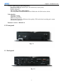
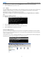
1.2 Front panel
Fig. 1-1
1.3 Back panel
Fig. 1-2
2
Chapter 1. AP-5004 Overview
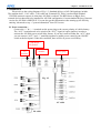
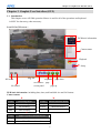
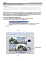
2. Installation
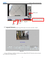
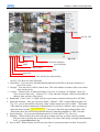
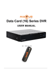
Please refer to the wiring diagram of Fig. 1-3. Standard delivery of AP-5004 package include
The machine itself , 1*AV cable , 1*IO cable and 1*manual CD. There is no hard disk included
UNLESS customer requests it at the time AP-5004 is ordered. The RED boxes on Fig. 1-3 are
external devices that need to be installed for AP-5004 configuration. Current standard delivery firmware
version for AP-5004 is MDVR2.X. You can also get this information after running up AP-5004 by
entering “advanced set up ->”system information” from GUI screen.
2.1 Power connection Connect the “+” & “—“ terminals on the power plug to the correct polarity of vehicle battery.
The “ACC” terminal needs to be wired to the “ACC” signal of engine ignition, in order to
activate the AP-5004 power-on/off delay feature. If you don’t want to bother the “ACC”, then
you can connect “ACC” and “+” terminals together to enable power control by the ON/OFF
switch at the back panel. Under this condition, there will be no power-on/off delay..
USB Mouse /
Keyboard
TV
monitor
VGA
monitor
Power plug
Fig. 1-3
AV cable
IO cable
3
Chapter 1. AP-5004 Overview
2.1 Capture-in
Insert the AV cable connector that comes with AP-5004 to this plug to retrieve camera video
signals and audio inputs. AP-5004 can support 4 cameras. The audio RCA plugs are reserved for future
use. Connect camera video outputs to the BNC leads on this connector.
2.2 VGA monitor
Although there are two VGA outputs on Fig. 1-3, VGA1 & VGA2, currently only VGA1 is
available. VGA2 is reserved for future use. You can connect a VGA monitor on VGA1 to have local
live view and do playback or configuration.
2.3 TV monitor
The S-Video output on Fig. 1-3 is to connect to a TV monitor.
2.4 DIO connector
AP-5004 can support 4IN and 4OUT dry contact IO points. Plug the IO cable that
comes with AP-5004 to this connector. Each IO has uses a set of 2 pins ("+", "-")
2.5 RS485 interface
AP-5004 has a RS-485 interface for PTZ camera control. This is combined on
the DIO connector, as on Fig. 1-3, “DATA+”, “DATA-“ and “GND” leads are
for RS-485.
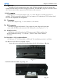
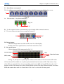
2.6 Hard disk / SSD card installation
AP-5004 uses 2.5” SATA hard disk or SSD card. The installation procedure is as follow:
2.6.1 Remove hard disk from AP-5004 cabinet.
Loosen the screws on hard disk tray that tights with AP-5004 cabinet as Fig. 1-4
Fig. 1-4
2.6.2 Pull out the hard disk tray as Fig. 1-5
Fig. 1-5
4
Chapter 1. AP-5004 Overview
2.6.3 Loosen the 4 screws at the two sides of the hard disk tray and lift up the plastic tape to move
tape out the hard disk. Then you can exchange the hard disk or install a new one.
Fig. 1-6
screw
screw
2.7 USB Mouse - You need a mouse when you want to do the system configuration or back up
record files. There are 4*USB ports on AP-5004. Two at the back panel and the other
two at front. If you don’t use mouse, you can use IR remote controller to operate it.
3. External 3G modem an GPS modem installation
You will need an external 3G modem for communication between AP-5004 and control center.
If you also want to have GPS tracking with e-Map support on SecuTrack CMS, then, you will need
a GPS modem. Please refer to the documentations “FW MDVR1.x 2.x 3G-GPS configurationguide” and “ 3G basic Knowledge” for more information.
4. Note
4.1 Camera power – The 12V camera power is NOT included in AP-5004. It has to come from
battery of the vehicle. If you need assistance, please consult your local reseller or e-mail
to [email protected]
4.2 Vehicle camera – You may need small size or weather proof cameras for the installation.
If you have difficulty in finding them from your local market, please consult
[email protected]
4.3 Video / Audio cable – Cables connecting video & audio signals from cameras or
microphones to AP-5004 are important to ensure the video / audio quality. Please use proper
quality AV cable to avoid noise generation.
5
Chapter 2. Getting Started
Chapter 2. Getting Started
Please connect a VGA monitor on “VGA1” or a TV monitor to “S-Video” of AP-5004 back panel for
local live screen. AP-5004 has delay power ON / OFF after the vehicle ignition is turned ON or OFF, if
the “ACC” signal is connected. ( Please refer to section 2.1, chapter 1).The default delay ON time is 15
seconds and delay OFF time is 30 seconds. So, please wait a little bit for VGA screen to show up after
power ON.
AP-5004 can support maximum 4 channel cameras. So, those buttons or indicators for operations on
more than 4 channels, are NOT workable on AP-5004.
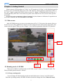
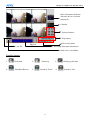
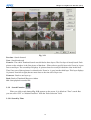
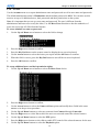
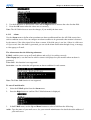
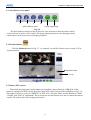
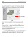
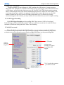
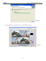
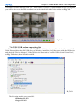
2.1 Main screen
After AP-5004 boots up, you can see its main screen as Fig. 2-1.You can see the camera videos on
local VGA screen. The graphical user interface (GUI) composes of the control panel, status panel, and
camera selection panel. Please go on to Chapter 3 for a detailed explanation about the GUI operation.
status
Fig. 2-1
Camera
selection
2.2 Running mode of AP-5004
control
There are two kinds of running modes on AP-5004, “mouse” mode or “IR control” mode. The
factory-default operation mode is “mouse".
2.2.1 Change running mode.
You can change AP-5004 running mode back and forth between “mouse” and “IR Control”.
Each time you change mode, AP-5004 will reboot to take the change into effect. Please be noted,
6
Chapter 2. Getting Started
you can configure or operate all the advanced functions ONLY at mouse mode.
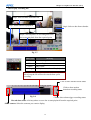
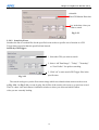
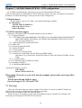
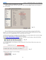
2.2.1.1 From mouse mode to IR mode
You can change it to “IR control” mode from the main screen by clicking the “Setup”
button, enter “system configuration”. Under “Running mode”, change the “Control” field
from “mouse” to “IR” and then click “OK”. AP-5004 will reboot and change to IrDA
control mode.
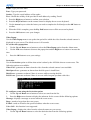
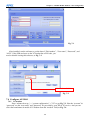
2.2.1.2 From IR mode to mouse mode –
Follow these instructions to switch from IR remote control running mode to mouse running
mode:
1. Press the Menu button on the remote control to display the setup menu on screen.
Menu button
Fig. 2-2
2. Use the up and down arrow buttons to highlight the Running Mode option and press the OK
button to confirm your choice.
The running mode menu will be displayed on screen.
3. Use the up and down arrow buttons to highlight the Control – IR Control field.
4. Use the left and right arrow buttons to toggle between Control – IR and Control – mouse.
5. Press the OK button when the control field is set to mouse.
The unit will reboot when the OK button is pressed. It will restart in mouse running mode. Please
refer to Chapter 4 for IR control OSD operation.
7
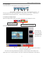
Chapter 3. Graphic User Interface (GUI)
Chapter 3. Graphic User Interface (GUI)
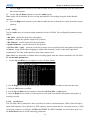
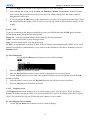
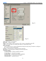
3.1 Introduction
This chapter covers AP-5004 operation. Mouse is used for all of the operations and keyboard
is ONLY for data entry, when necessary.
Local VGA GUI screen :
DVR basic information
Camera status
Playback
Setup
Fig. 3-1
full screen
sequential page down
surveillance page
screen panel
page up
IO control
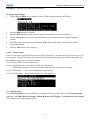
DVR basic information: including date, time, total hard disk size and LAN status.
Camera status:
R
M
Color
Recording Mode
Color
Motion detection Status
Gray
No video signal
Gray
Motion not detected
Blue
No recording
Yellow
Motion detected
Red
Full recording
G
Color
Status of each DI and DO device.
Gray
DI or DO not detected
Red
DI or DO was detected
8
Chapter 3. Graphic User Interface (GUI)
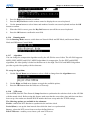
3.2 Surveillance screen panel
The Surveillance screen panel enables you to define which live images are displayed on screen.
A
Fig. 3-2
A. You can select 1 / 4 split-screen display.
Fig. 3-3
B
C
B. Use the sequence button to automatically cycle through all the connected cameras.
C. The arrow buttons to page down or page back cameras.
D
F
Fig. 3-4
E
D. Enlarge button
Click the enlarge button to switch to full screen live video display.
Double click mouse right button to switch back normal live video.
E. IO control button
Click to bring up GPIO status panel as Fig. 3-5.
current status
clear
GPO status
historical status
close
Fig. 3-5
On Fig. 3-5, the top row of yellow points indicate current status of GPI. It becomes RED when
GPI is activated. The middle row of yellow points indicate historical status of GPI. That means, if any
of the GPI was activated before, the corresponding point became RED and stay RED unless the “clear”
button is clicked. The bottom row yellow points indicate current GPO status. When activated, it becomes
RED and remains there until it is de-activated. Click “close” to close this IO status panel.
9
Chapter 3. Graphic User Interface (GUI)
Live Single Camera View
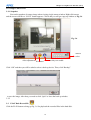
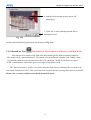
3.2.1 Snapshot
You can do snapshot of camera image when viewing single camera window. Right click mouse
and the screen will have a “SAVE” button appears. Click it and you will get a pop up window as Fig.3-6
Fig. 3-6
camera
select
video adjustment
overlay text enable
IO control
Click “OK” and then you will be asked to select a back up device. Then, click “Backup”
to save the image. After that, you need to click “Quit” to leave the back up window.
3.2.2
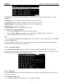
3-3 PLAY Back Record file
Click the PLAY button to bring up Fig. 3.6 for playback the recorded files in the hard disk.
10
Chapter 3. Graphic User Interface (GUI)
Basic information indicates
date/time & size of current
playing file.
Calendar
Function buttons
Play buttons
Split-screen buttons
Lock file
Fig. 3.6
Recording data status information
Back to live surveillance
Function buttons:
1.
Bookmark
2.
4.
Thumbnail Browse
5.
Alarm log
Search by Event
11
3.
6.
Backing up the data
Search by Text
Chapter 3. Graphic User Interface (GUI)
How to play recording file:
Step2: Select an hour from time line.
Step3: Select camera to playback.
Step1: Select a date from calendar.
Step4: Click anywhere on recording data score
bar to start playback from the required point.
Fig. 3.7
Date Color
Red
Meaning
Have recording data
White
No recording data
Square
Today’s date
Orange
The day that was selected for playback
Lock file: click the score bar under time line can lock
file to keep the file will not be erased when cyclic
recording.
Click to show normal record status
Click to show motion
detection recording status
Fig. 3-8
Click to show alarm trigger recording status
Record data status: click anywhere on score bar to start playback from the required point.
Select camera: Select the cameras you want to display
12
Chapter 3. Graphic User Interface (GUI)
3.3.1. Play buttons:
Use the Play buttons to control playback of stored footage from the cameras.
Step backward Step forward Play Pause Control playback speed(1/8x ~ 4x)
The fastest speed of the single image playback is 4x; slowest speed is 1/8x. Click “+” button once to
double playback speed from normal. Click “-” button will decrease playback speed.
3.3.2. Split-screen display buttons:
Split-screen display buttons enables you to define which split-screen is displayed on screen.
Selectable 4 split-screen
The arrow buttons to cycle through
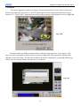
3.3.3. Video adjustment when playback
“water mark” flag.
becomes RED if the
video was modified
Only appears when
single camera view
Fig. 3-9
These buttons ONLY appear when single camera window is
selected on local display screen
You can do camera image adjustments for brightness, contrast, sharpness and smoothness when
single camera view is selected at playback. Click “pause” and then do the adjustments via the buttons as
13
Chapter 3. Graphic User Interface (GUI)
Fig. 3-10. You can also zoom in specific point of the image to get clear view.
Brightness
Contrast
Sharpness
Zoom-in
Restore
Smooth
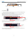
3.3.4. Status Button
The status panel displays the playback status of the current record. The aqua line (Data) indicates
record data over an one hour time interval, as Fig. 3-8.
Click “motion status button” on Fig. 3-10 to show motion status of the record file. The yellow bars
(Motion) indicate the instance when motion was detected. On Fig. 3-10, camera#1 had
motion trigger started from around 22:00 till 32:00 minutes in this hour.
motion
status
button
Fig. 3-10
motion trigger
indication
Click GPI status button to show GPI trigger status of the record file as Fig. 3-11. The vertical small
orange bars indicate when GPI events were detected.
play back cursor
GPI status
button
Fig. 3-11
GPI triggers detected
The vertical yellow line on Fig. 3-10 is the playback cursor. Click anywhere on the Data, Motion, or
GPI lines to start playback from that point.
14
Chapter 3. Graphic User Interface (GUI)
3.3.5 Bookmark
User can have bookmarks at the specific time during playback.
Bookmark:
1. During playing recording file user can click
“bookmark” button to mark the specific time
point.
2. User can write down the note and click “Add”
button to save it. The new bookmark file will
be locked.
3. Select one of the lists of recording file in
bookmark field and click “play” button to
playback.
Fig. 3.12
3.3.6 Alarm log
Any alarm will be written into alarm log including motion triggerǵGPIO triggerǵDisk errorǵVideo loss
ǵPOS event.…..etc. User can search alarm log by specific time and double click one of the alarm log on
the list to playback the video.
Fig. 3.13
15
Chapter 3. Graphic User Interface (GUI)
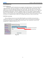
3.3.7 Backing up
You can back up record files to VCD/DVD RW or USB HDD drives. Click the “backup” icon.
Fig. 3-14 shows the back up device found. Here we have “USB Flash Disk”. Then, click “OK” to
back up device currently connects to
this machine
check to
select it for
back up
Fig. 3-14
bring up Fig. 3-15. If you answer “OK”, AP-5004 will clear all data on the USB Flash Disk.
Fig. 3-15
Fig. 3-16
If you click “Cancel”, then, Fig. 3-16 shows you how much space left on the USB Flash Drive
before doing file copy. You then need to select the date / time and cameras on Fig.3-17
Fig. 3-17
Fig. 3-18
16
Chapter 3. Graphic User Interface (GUI)
Then, click “OK” to start file copy as Fig. 3-18. After completed, Fig. 3-19 show you the result of
Fig. 3-19
how many files, size and date / time period that was back up.
For back up to VCD/DVD RW, the procedure is similar, but you will need to answer the burning speed
you want. The default speed is X5.
Note: It takes some time for AP-5004 to get video data before it can start the back up process.
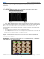
3.3.8
Thumbnail Browse
Finds video images and selects them for processing individually, in whole folders, using a simple time
selector and built-in image viewer .you can check out the results with the built-in viewer.
1. Select search starting time and camera.
Fig. 3.20
2. Using a simple time selector and built-in image viewer .You can check out the results with the built-in
viewer.
17
Chapter 3. Graphic User Interface (GUI)
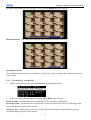
Fig. 3.21
Previous - Search forward
Next - Search backward
Zoom in - The whole Thumbnail search was divided to three layers. The first layer is hourly based. Each
picture on the windows is the first picture of that hourΖWhen select a specific hour to do Zoom in, it goes
into second layer. The second layer displays 16 pictures based on evenly divided time slots in this hourΖ
Then if any one of these pictures is selected to do Zoom inΔit goes into the third layer. This layer displays
16 pictures from left to right, that are most close to the time slot of layer twoΖ
Zoom out - Back to one layer upΖ
Back- Back to Thumbnail Browser window
Ok - Start playback recorded file
3.3.9 Search Function
When you click search button, Fig. 3-22 appears on the screen. It is default at “Time” search. But
you can select “GPI” or “Motion Detection” from the “Rule Selection” field.
3.3.9.1 Search by Time
18
Chapter 3. Graphic User Interface (GUI)
selectable
Time/GPI/Motion Detection
key in the date / time you
want to search
Fig. 3-22
3.3.9.2 Search by Event
Searches the list of recorded files for the specified event such as a specific area of motion or a GPI
Trigger that occurred within the specified time interval.
Search by GPI Trigger:
1. Select the GPI# you want to search
2. Select “All Time Range”Ε”Today”Ε”Yesterday”
or “User Define” for quicker searching.
3. Click “ok” to start search GPI Trigger files in the
specific time.
Fig. 3.23
The search result gives you the first camera image which was related to that camera on the screen.
as Fig. 3.24 . On Fig. 3-24, you can do play, list all files of the search, select next or go previous record.
There is a date / time and camera # indication window to show you when and which camera
video you are currently looking.
19
Chapter 3. Graphic User Interface (GUI)
date/time/camera#
indication
Back
Fig. 3-24
search result list
previous record
replay
next record
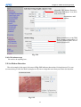
3.3.10 Search by Motion
On Fig. 3-23, if you select motion detection as Fig. 3-25, the screen of Fig.3-26 will pop up
for your selection of the motion detection area.
1. Select motion detection of the camera# you want
2. Select the time period you want. It can be “All Time
Range”Ε”Today”Ε”Yesterday” or “User Define”
3. Click “ok” to start search motion files at that
specific time range.
Fig. 3-25
20
Chapter 3. Graphic User Interface (GUI)
4. And then select search area by mouse left
button drag.
5. Click “ok” to start searching motion files at
that specific area.
Fig. 3.26
Search result and following operations are the same as Fig. 3-24.
3.3.11 Search by Text
( This function is NOT available on firmware version MDVR 2.0 )
This function is to search record video files that contain specific POS text data for playback.
This search can be “transaction based”. That means you can define the “starting” and “ending” string
of a bill and search the text you want in this deal. You can define 3 fields of search text in logical
“AND” combination to search. This gives you unique results of the search.
The “Device Selection” section is for you to select the POS devices( channels) that you want to do
text search. Default is all “ON”. This is no harm even if you do not have so many POS devices connected.
Please refer to section 3.6.10 for more detail about POS device.
21
Chapter 3. Graphic User Interface (GUI)
starting string of a transaction
ending string of a transaction
the strings you want to search in logical
“AND” combination
POS device selection default
all “ON”
Fig. 3-27
The search result is as Fig. 3-28. The first record of the search result is playing on the screen. But the
background searching keeps going. After searching completes, the record list shows up at the bottom of
the screen. You can then click any one record in the list to play.
On Fig. 3-24, the playback is single camera based. POS text is overlay on the camera video in “white”
color. There is a POS text window at left button of the screen where you can see the complete POS text
in the record.
22
Chapter 3. Graphic User Interface (GUI)
overlay
POS text
POS text
panel
when checked, enable overlay POS
text on video,
search result list
scroll up/down to see complete POS text
Fig. 3-28
Note : Click the
“search result list” button to show the record list of search
Fig. 3-29
23
Chapter 3. Graphic User Interface (GUI)
3.4 Snapshot
You can do snapshot to capture one image of current playback file by click “pause” button and
then, mouse right click. You will see a “SAVE” button appears on the image screen and mouse cursor
becomes “X”. Click “SAVE” button and you will get a pop up image on the playback screen as Fig. 3-30.
Fig. 3-30
You need at least one USB pen disk inserted on AP416 as back up device. If you answer “OK”,
then, you will be prompted for back up device selection as Fig. 3-31. Select the device and then click
“Backup” to save the image. The file name saved has the format “snapshot(X)_yyyymmdd_hhnnss.jpg”
Where (X) is the camera number starting from 0 as camera#1.
Fig. 3-31
24
Chapter 3. Graphic User Interface (GUI)
3.5 Close playback screen
Stop playback recording file and back to the recording file list menu.
[ System setup]
3.6
Setup
Click the Set Up button to enter AP-5004 system configuration menu. There are sub menus,
System Setup, Record Setup, Alarm and Motion Detection can be configured.
This section explains each of the menu pages in turn.
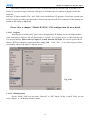
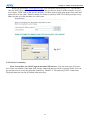
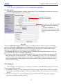
3.6.1 Password Protect ( for local access )
Here you can set password protection, administrator and user passwords, auto lock period or lock the
system immediately. The passwords are “*” encrypted, so that you need to enter twice for confirmation.
double click to bring
up on screen keyboard
operation locks after
the # of seconds you
enter and request for
password
“Admin” & “User” here are
for login from local VGA
screen
Fig. 3-32
If you enter number of seconds in “Autolock” field, you will need to enter password when you want
to do any operation after the number of seconds you set. “Lock Now!“ is to lock and ask for password
immediately.
Note: If you do not have a keyboard connected to the system, you can use the on-screen keyboard to
enter your passwords. Double-click the field to display the on-screen keyboard and use mouse
selection for characters entry.
25
Chapter 3. Graphic User Interface (GUI)
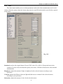
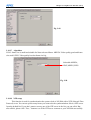
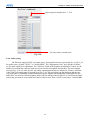
3.6.2 Video
The Video menu enables you to set video parameters such as the video standard and so on for each
camera. Select the camera from the Camera drop-down box and fill in the details in each field as required
using mouse.
Fig. 3-33
Standard: sets the video signal format. Choose NTSC in the US, or PAL in Europe and most Asian
countries. If you are not sure about this option, select Auto. AP-5004 will detect the video standard
automatically.
Brightness: adjusts the amount of light or brightness for the selected camera according to your
preference.
Contrast: adjusts the difference between light and dark areas or contrast for the selected camera
according to your preference.
Saturation: adjusts the amount of color for the selected camera.
26
Chapter 3. Graphic User Interface (GUI)
Hue: adjusts the dominant color for the selected camera.
Quality: adjusts the video quality for each camera. The default setting is 80. We recommend that you do
not set this to 100 to avoid a slower rate of video transmission and using up a significant amount of
hard disk space.
Compression Boost: This is ONLY valid for H.263 algorithm. Its purpose is to lower video data rate.
But it sacrificed video quality.
Auto Gain Control: enables automatic gain control to adjust the video signal strength.
Water Mark: Sets water mark protection on the video image.
Local Display: enables viewing the selected camera video signal on the local display. If this option is set
to Off, the camera is still optional and its video can be recorded if needed.
PTZ Device: Select PTZ model from the support list. If you can’t find it, please contact your reseller.
PTZ baud rate: each camera have different baud rate, please set correctly.
PTZ time out: The timeout value represents the time given to the camera in responding to a command.
PTZ ID: each camera can define different ID, please set correctly when you have more than one PTZ
cameras in one AP416 unit.
Dimension: sets 320 x 240 or 640 x 480 resolution for each camera.
Copy Camera Configuration To : User can select cameras and press “ok” button to copy the
configuration of current camera to the selected cameras.
3.6.3 Disks
This is for the configuration of network disks such as NAS or NFS server If nothing is connected,
(No Device) appears on the Disk Device field.
Fig. 3-34
Use keyboard or mouse to enter the IP address and Volume of any connected network disk. Click on the
Test button to test if the drive is connecting correctly to AP416 machine.
27
Chapter 3. Graphic User Interface (GUI)
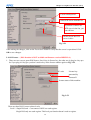
3.6.4 TV output
Use the TV Output menu to configure the video output of AP416. It can be standard VGA computer
monitors or TV type screens. Set the device type, standard, outputs and other parameters. Set the Camera
(From) and Camera (To) options to specify the range of cameras that are displayed in the cyclic display
mode. Software based De-interlace support.
VGA/TV selectable
select composite or S-video
time between cameras change
select the cameras to be display
selectable 1/4/9/16 split
Fig. 3-35
Use mouse to set each field. Ensure each field is set correctly before clicking OK. If parameters are set
incorrectly it could result in the display becoming unreadable and very difficult to correct.
3.6.5 OSD Text
Use the OSD Text menu to assign text for each camera. This makes it easier to refer to cameras by
their names.
select camera
set position
enter text here
select text color
Fig. 3-36
28
Chapter 3. Graphic User Interface (GUI)
To set up the OSD text:
1. Select the desired camera from the Camera drop-down box.
2. Click the Enable field to display the text.
3. Adjust the position of the text display on the image using the X and Y parameters. A value of X=0 and
Y=0 would result in the text appearing at the top left corner of the camera image. Increasing the value
of Y moves the text down the screen. Increasing the value of X moves the test the right. Enter the text
to be displayed in the Text field.
4. Enter text you want to put on that camera view
5. You can select the text color
6. Click OK to save changes.
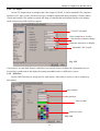
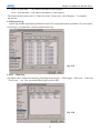
3.6.6 GPI
The GPI (general purpose input ) menu enables you to view the status of the input devices such as
switches, sensors.. etc. When the switches or sensors change state, the GPIs show the status of these
input devices. The GPI devices can be NC (normally closed) or NO (normally open) as the state when
they are not activated. A GPI that is set at “N.O.” on Fig. 3-37, becomes activated when it is closed.
These status change, can be seen on Fig. 3-5.
selectable N.O. or N.C.
Fig. 3-37
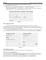
3.6.7 TCP/IP
There are two Network Devices on this setting. That means AP-5004 machine can support max. 2
network interface cards. Normally, one is enough and that is the standard delivery of AP-5004. If
customer wants to add one more network interface for any reason, he can do that with proper setting here.
Gateway and DNS IP are necessary if you want the camera videos of this AP-5004 can be access
from remote PC client through Internet. If you change HTTP port other than “80”, you will need to
29
Chapter 3. Graphic User Interface (GUI)
tag the port number following IP address of the unit. Consult your network manager if you don’t
understand how to do.
normally one set is enough,
unless you want to use two
network cards
May use port other than 80. If
this is the case, then, tag port#
following IP when using HTTP.
Fig. 3-38
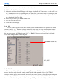
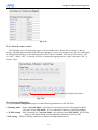
3.6.8 Account ( for remote ONLY)
Use the Account menu to set up the administrator as well as User name and password. The accounts
configured here are all for remote access ONLY. Max. 256 additional remote access authority users’
password, permissions can be configured on the system. Select the user number and assign a Name and
password to it. Click the PTZ, Playback, and Audio fields to enable access to these properties for the
selected user. Select the cameras that you want the user to have access to and set them to Yes.
remote administrator authority
Everything creates here ONLY
have remote access authority
max. 256 users
Fig. 3-39
30
Chapter 3. Graphic User Interface (GUI)
3.6.9 Audio
Mic Gain – Adjust microphone input signal level,
Speaker – For speaker volume adjust
Mic Timeout and Speaker Timeout – Time out period setting for remote access.
Self Test – Local test from microphone to speaker.
Camera n – Select audio source that is to relate with the camera. AP-5004 has ONLY one audio source
from mother board, so you have ONLY one choice here.
speaker volume adjust
remote access
time out period
selectable audio source
related to this camera.
AP416 has one audio
ONLY, so here you have
only one choice
Fig. 3-40
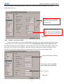
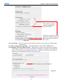
3.6.10 POS Lan Device ( This function is NOT available on firmware version MDVR 2.0 )
selectable Device1-Device16
POS software needs to do this
show up automatically if connect success
click to access that device
selectable 192.168.0 to 192.168.255
click “RESCAN” will reboot AP416
Fig. 3-41
31
Chapter 3. Graphic User Interface (GUI)
AP416 can receive POS text from LAN port. There are two methods:
3.6.10.1 Direct connect – If the POS machine can send out POS text through its LAN Port, then, you
can connect it directly to the LAN that AP416 can access it. The configuration procedure is:
3.6.10.1.1 Select POS LAN device – There are 16 devices maximum.
3.6.10.1.2 Select Static or Dynamic IP. When Static IP is selected, key in the IP address and port
number of POS machine. When Dynamic is selected, click “Select & Update”, then, if the
connection is OK, the “Device Name” will show up automatically. In order to use Dynamic
IP, the POS LAN machine needs to include a OCX registry command in its software for
AP416 to recognize it. Please contact [email protected] for detail.
3.6.10.2 Using AP-204 – AP204 is a RS232 to LAN converter. You can connect its RS232 to POS
machine and its LAN port to the hub or switch that connects AP416. The AP-204 units that
connect to the same AP416 DVR, should have same IP segment. First, select its IP prefix
under “NetIO” section of Fig. 3-41. Then, enable and click “Rescan”, AP416 DVR will
reboot scan the network to see if there are AP-204 units inside its LAN segment and bring
up the MAC ID. Only after this process, you can select the “AP204-X” at “NETIO” field.
The IP prefix selected, must NOT be occupied by other AP-204 units group.
ONLY after you finish configure this step successfully, you can then go to “Serial
port” configuration of section 3.6.11 to combine the POS LAN device with cameras.
3.6.11 Serial ports
The “Serial port” here includes NOT just the traditional RS232 COM port. It covers AP204,
RS232 to LAN converter and POS LAN devices from POS machine that are set up in previous
section 3.6.10.
selectable COM / AP204 /
(SIP)LAN/(DIP)LAN
select physical devices
For PTZ camera control adjustment
If “No” is no good, then change to
.”Yes” and vise versa.
select POS text
color
select POS text
position
Fig. 3-42
32
Chapter 3. Graphic User Interface (GUI)
3.6.11.1 Port – You have selections here “COM”, “AP204”, “(SIP)LAN” & “(DIP)LAN”.
COM ports are the COM1 & COM2. On AP-5004, COM2 is RS485 dedicated for PTZ camera
control. “AP-204” is the RS232 to LAN converter that you set up at section 3.6.10. Only
the AP-204 units that were connected successfully will show up here. (SIP) LAN is the LAN
connection from POS machine with “static IP” address. (DIP)LAN is the POS machine with
“dynamic IP” connection to AP-5004.
3.6.11.2 Device – Here the selection varies with different categories form “Port”.
When “Port” is COM1 – you have selection of modem/GPIO/PTZ camera/Data capture.
When “Port” is COM2 – you have selection of GPIO/PTZ camera/Data capture.
When “Port” is AP-204 – you have Data capture.
When “Port” is (SIP)LAN or (DIP)LAN – you have Data capture.
The meaning of configuration here is you want to connect the “Port” selected to a physical
external device. For example, when “Port” is “COM1”, you can connect it to a “modem” or
GPIO that has RS232 serial interface. You then will need to set its “speed”, “data bits” as on
Fig. 3-42. When the “Device” is “Data capture”, that means you are connecting POS machine
for transaction text overlay with camera video. You can then select the text color and position
on screen. There are 4 positions. “Upper left”, “Upper right”, “Lower left”, “Lower right”.
You can also enable the background color of POS text to get better view of POS text when
necessary.
3.6.12 System info
This section display many useful and important information which are necessary for AP-5004
health checking and debugging. There is nothing to change here. But you will probably be requested
Fig. 3-43
to give the maintenance people these information when the machine is no good. So, it is wisdom to keep a
record of this page.
33
Chapter 3. Graphic User Interface (GUI)
3.6.13 Date/Time
Select your correct time zone at “T.Zone” field. The year/month/date/hour/minute/second also can be
configured. AP-5004 will reboot to the new time zone after click “OK”.
Time zone select
Year / Month / Date / Time
set up
Fig. 3-44
3.6.14 ISP
If you are using dial-up access to the Internet, use the ISP menu to enter the necessary details for login to
your Internet Service Provider. The TCP/IP data is assigned by ISP. So, make it automatic here.
telephone number to dial up
to ISP
User name &
password to login ISP
assign by ISP
Fig. 3-45
34
Chapter 3. Graphic User Interface (GUI)
3.6.15 PPPoE
for ISP login
If “Yes”, connect to Internet
automatically when AP416 start
up, if “No, then, you need to click
“connect” manually
click to connect
Fig. 3-46
This section provides another way for connecting AP-5004 to Internet. PPPoE uses your existing
LAN to dial up to your ISP for Internet service. You don’t need a telephone line here. But you do need
an ISP login account name and password. You can set two DNS( Domain Name Server) IP addresses.
If you use URL here, then, you need to set the DNS physical IP correctly at Fig.3-38.
You can click the “Disconnect” button to break the Internet connection and the “Connection Status”
field shows “Connect succeed” or “Connect Fail”.
3.6.16
3G
select the USB port for
3G modem
this varies with different areas. Please
check your local telecom service
company to see if it is necessary
Fig. 3-47
35
Chapter 3. Graphic User Interface (GUI)
This function enables AP-5004 to connect to Internet through an external USB 3G modem. You
need a 3G account for login. Select the USB port of AP-5004 where 3G modem is plugged. Select the
baud rate
and enter 3G phone number. The “Apn” field varies with different 3G operators. You need to consult your
local 3G service provider to get the number. Some areas may not need it for connection. Other buttons are
similar to ISP setting as Fig. 3-45.
Please refer to chapter 7 Mobile DVR 3G / GPS configuration for more detail.
3.14.15 Registry
This function is useful ONLY when you are using dynamic IP address for the AP-5004 machine
when connecting to Internet. The AP-5004 needs to “register” to a “registry server” so that client PC can
visit it from Internet. Please refer to Chapter 5, remote function for detail. You can set up here the IP
address, HTTP port number, registry path here at Fig. 3-48. Click “Test...” to see if the registry is done
successfully and save the data for “registry server.”
Fig. 3-48
3.14.16 Running mode
On the “Mode” field, you can select “Network” or “ISP” Mode. On the “control” field, you can
select “Mouse” or “IR Remote Control” Mode.
36
Chapter 3. Graphic User Interface (GUI)
Fig. 3-49
3.14.17 Algorithm
H.263: frame size is small and suitable for Network surveillance. MPEG4: Video quality good and frame
size small. JPEG: Video quality best but frame size big.
Selectable MPEG4,
H263,MJPEG, JPEG
Fig. 3-50
3.14.18 NTP setup
This function is used for synchronization the system clock of AP-5004 with a NTP( Network Time
Protocol) server. You can set up how many hours you want to do the synchronization. Select a NTP server
from the default list. If you don’t want to use any one of the NTP server in the list, you can edit it. But
after all this, please click “Test...” button to see if the NTP server connects to your AP-5004 successfully.
37
Chapter 3. Graphic User Interface (GUI)
Clock refresh period
select NTP server from the list
if you don’t want to use
NTP server in the list, you
can edit here
click to test if the NTP
server is alive
Fig. 3-51
After making the changes, click on the Test & Save button to verify that the server is operational. Click
OK to save changes.
3.14.19 License : ( POS function is NOT available on firmware version MDVR 2.0 )
1. There are two ways to grant POS license. One is key-in license key; the other one is plug-in a key-pro.
So if you plug-in a key-pro you don’t need to key in the license number again on Fig. 3-52.
PC code
License key
generated by
Formosa21
license status of this machine
Fig. 3-52
There are three POS License to three levels:
Level 1: Single POS unit – Can connect ONLY one cash register.
: Single POS only one cash register. This level pos function doesn’t need to register.
38
Chapter 3. Graphic User Interface (GUI)
Level 2. 4 POS units – Can connect maximum 4 cash registers.
Level 3. Full functions – Can connect maximum 16 cash registers.
The Hybrid license can be max. 16. After key in the “License key”, click “Register...” to complete
the process.
3.14.20 System Log
System log includes operations performed at local VGA screen and remote operations. User can search
system log by year/date/time. Not all operations have log.
Fig. 3-53
3.14.21 Alarm Log
Any alarm will be written into alarm log including motion triggerǵGPIO triggerǵDisk errorǵVideo loss
ǵPOS event.…..etc. User can search alarm log by specific time.
Fig. 3-54
39
Chapter 3. Graphic User Interface (GUI)
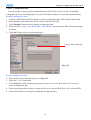
3.14.22 Configuration File:
You can backup or restore system configuration into a file for future restore in case of something
wrong that causes loss of configuration, or restore it to another machine in case it has similar functions.
Backup configuration data:
1. Connect a USB flash to DVR for backup or restore configuration data. DVR will auto detect flash.
2. Select backup section and click a device, which is shown in the field.
3. Click “Backup” button to start to backup configuration data.
4. When user sees “vpcfg _ your DVR name _ Mac ID.bin” was saved in the field, it mean the backup
was done.
5. Click “ok” button to leave system setup menu.
back up device detected
Fig. 3-55
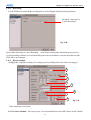
Restore configuration data:
1. Select restore section and click a device, as Fig. 3-55
2. Select one “*.bin” in the field.
3. Click “Restore” button will pup-up a menu to ask you to over write data. Select “ok” to start to
restore configuration data.
4. When restore data action was done, system will ask you to reboot DVR. Press “ok” to reboot DVR.
5. After restart DVR, user will get the configuration setup data back.
40
Chapter 3. Graphic User Interface (GUI)
select device to restore
select configuration file
to restore from
Fig. 3-56
3.14.23 Default settings
Select “Yes” here and click “OK” button to restore default setting to AP-5004. The default
administrator name and password are “webmonitor” and “oyo”. Default IP address is 192.168.10.10.
Fig. 3-57
41
Chapter 3. Graphic User Interface (GUI)
3.14.24 Revise firmware
Here you can do firmware revise from local VGA screen as Fig. 3-58 below. You can put the
firmware binary file in a VCD/DVD or USB HDD. You will be asked to select the device that is to be
used for revise firmware. Select the device and firmware file, then click “OK” to start the process. After
completed, the machine will do reboot into new firmware.
Fig. 3-58
3.14.25 Reboot system
“Shutdown” turns off the power and “Reboot” only re-start the machine from beginning, does
NOT turn it off physically. You can select either one and click “Yes”.
Fig. 3-59
[ Record Setup]
42
Chapter 3. Graphic User Interface (GUI)
3.15.1 DVR setup
Use the DVR menu under the Record Setup tab to set the Digital Video Recorder parameters.
selectable “Auto stop” or
“Cyclic Recording”
Fig. 3-60
Select either Auto Stop or Cyclic Recording. Auto Stop recording stops when disk space runs out.
Cyclic Recording continues to record until disk space runs out and then overwrites the oldest records.
Click OK to save changes.
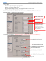
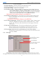
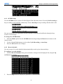
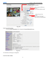
3.15.2 Record schedule
On Fig. 3-61, weighted recording is for setting special recording frame rate when event triggers.
1
2
3
4
5
6
9
7
8
Fig. 3-61
Other selections are as below:
3.15.2.1 Select Schedule –You can set up to 16 record schedules here but ONLY those which “Enable”
43
Chapter 3. Graphic User Interface (GUI)
as “Yes” are activated.
3.15.2.2 Recording days – Click the week days to select the days for record
3.15.2.3 Recording period – Key in the start and stop time to record.
3.15.2.4 Audio recording – Click “Yes” to record audio
3.15.2.5 Weight recording – “Weight recording” is a feature that records at higher frame rate
when something happens. Normally, if nothing happens, you can record at lower
frame rate to save disk space. But when event triggers, you want to record faster
so that you can see more detail. Select “Yes” to enable this function.
( This function is NOT available on firmware version MDVR 2.0 )
3.15.2.6 Weight recording frame rate – Set the frame rate you want for weight recording. If more
than one event happens at the same time, the sum of the frame rate set is limited to
total system frame rate.
( This function is NOT available on firmware version MDVR 2.0 )
3.15.2.7 Camera recording mode – Selectable “No”, “Normal”, “Motion”, Alarm”, ”Motion+Alarm”,
“POS text”, “Intelligent” here. Please be noted, in “Motion+Alarm”, the “+” means
logically “OR”. That means, either motion detected or alarm trigger, will make the
camera record.
3.15.2.8 Camera recording frame rate – You can select recording frame rate for each camera.
But the sum of these frame rate should NOT exceed system total frame rate of
AP-8100. And this function is activated ONLY when “Auto speed” is set at “No”.
3.15.2.9 Auto Speed – When select “Yes”, recording frame rate of each camera is adjusted
automatically by AP-8100 firmware. If “No”, then, you can set for each camera, based
on the above 3.15.2.8
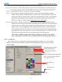
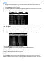
3.15.3 GPI Trigger
select the GPI you want to
relate with cameras
set recording time
If “Yes”, the camera records
when GPI1 is trigger
Fig. 3-62
On Fig. 3-62, you relate camera recording with GPI trigger. AP-5004 can have max. 16 GPI .
The trigger of each GPI can relate to the recording of multiple cameras based on your selection. You can
44
Chapter 3. Graphic User Interface (GUI)
set up the recording time for how long you want the cameras to record after GPI trigger. Remember to
make “Enable” as “Yes” to activate this function and click “OK” to save the configuration.
3.15.4 Text recording ( This function is NOT available on firmware version MDVR 2.0 )
This function is particularly for POS integration. If you don’t have POS machine connect to
AP-5004, you can skip this section.
There are two selections for each camera, “POS event” and “Text”. “POS Event” is defined at
“Alarm” set up section. This refers to some kind of special characters from POS machine. “Text”
means as long as there is character data from POS, don’t care what it is. You can also set how long
time the cameras to record at the “Record Time” field.
set how long time you want the
cameras to record
Selectable “POS Event”
or “Text”
Fig. 3-63
3.15.5 Pre-alarm recording ( This function is NOT available on firmware MDVR 2.0)
When alarm happens, the cameras can record ahead of the alarm max. 300 frames. You can set
the number of frames you want each cameras to record , as Fig. 3-64.
Fig. 3-64
45
Chapter 3. Graphic User Interface (GUI)
[ Alarm]
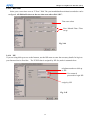
3.16.1 Alarm setup
The fields set up here at Fig. 3-64 apply to all kinds of alarms except the POS Event Text, which is
dedicated to POS integration. Click “Test” button to test if the e-mail can be sent successfully.
receiver’s e-mail address
how many times you want to send
the e-mail when alarm trigger
the interval in seconds between
consecutive e-mails
pop up a camera on VGA screen when
alarm for 20 seconds
key in the text to be defined as
Event 1
Fig. 3-65
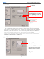
3.16.2 GPI Alarm
At Fig. 3-66, you define the actions when GPI1 triggers. “Message” means, show alert text on
VGA screen. “Beep” is to alert with audio. “Video Popup” is to pop up the camera video which relates to
46
Chapter 3. Graphic User Interface (GUI)
select GPI#
set the time period you
want to generate alert
click ON to enable
Fig. 3-66
GPI 1 on VGA screen, GPI#1 is related to camera#1, GPI#2 relates to camera#2,...and so on.
3.16.3 Motion Alarm
Fig. 3-67 let you set up the motion alarm generates from a specific camera. The setting is
similar to Fig. 3-66 except the camera selection.
select the camera to
generate motion alarm
Fig. 3-67
3.16.4 Video Lost
This alarm triggers when AP-5004 detects there is no video from the camera that connects to it.
Only “Beep” alert can be set. Select the camera# and others are the same as Fig. 3-67.
47
Chapter 3. Graphic User Interface (GUI)
select camera
Fig. 3-68
3.16.5 Disk Space Low
This alarm is valid ONLY when you set “Auto stop” at section 3.15.1 It triggers when the disk space
is full. So that customer can do proper actions to back up or change disks. “Message” , “Beep” alerts and
sending e-Mail can be configured.
Fig. 3-69
3.16.6 Disk Error
This alarm triggers when AP-5004 detects disk error. That means AP-5004 can not access, read or
write to the disk. Pop up message on VGA screen or audio beep alert can be enabled. Setting is similar
same as Fig. 3-66.
3.16.7 POS event: ( This function is NOT available on firmware version MDVR 2.0 )
This alarm triggers when “POS Event” happens. The POS Event text was defined at Fig. 3-63
48
Chapter 3. Graphic User Interface (GUI)
Fig. 3-70
Note: The text was captured from the POS machine; you should check what text will be sent from
the POS machine, then set appropriate text in POS Event.
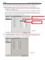
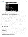
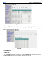
3.17 Motion Detection
You can set up Motion detection parameters for each camera on the screen of Fig. 3-71
1
2
3
4
Fig. 3-71
Fig. 3-71
The Procedure is :
1. Camera: Select the camera you want to do configuration.
2. Enable (Yes/No): Turn On/Off the motion detection function.
3. Sensitivity: Select sensitivity level default value is 50.
4. Use mouse drag on the screen and left click to set the detection area. Right click to clear the
detection. Or you can left click the small square rectangles to enable or right click to clear the
detection areas. Click OK to save changes.
49
Chapter 4: IR Remote Control Operation
Chapter 4. IR Remote Control Operation
4.1 Introduction
This chapter covers remote control operation using IR remote controller. The AP-5004 must be in IR
remote control running mode for this operation.
4.2 Main menu
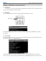
Press the Menu button on the remote control to display the main menu on screen.
Menu button
Use the Up and Down arrow buttons to select one of the four options and press OK button to confirm
your choice.
4.3 System setup
The System Setup menu enables you to change many different parameters of the AP-5004. This section
describes each option in the System Setup menu.
Use the Up and Down arrow buttons to highlight an option, and use the OK button to confirm your
choice. You can move between pages using the Prev Page and Next Page buttons on the remote control.
50
Chapter 4: IR Remote Control Operation
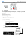
Up and Down
arrow buttons
OK button
Prev Page
Next Page
4.3.1 Password protect
Use the Password Protect option to enable password protection, set administrator and user passwords,
set the auto lock period and lock the system immediately. Enabling password protection prevents
unwanted users from accessing or configuring the AP-5004. The Password Protect menu has the
following choices:
Enable - enables password protection.
Admin Pass - sets the admin password.
User Pass - sets the user password.
Auto lock After - enables password protection after the specified time interval.
Lock Now! - enables password protection immediately.
To set the user or admin password:
1. Use the Up and Down arrow buttons on the remote control to highlight the Admin Pass option to set
the administrator password or the User Pass option to set the user password.
2.
Press the Right arrow button to display the password entry screen.
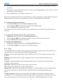
3.
Press the keypad button on the remote control to display the on-screen keyboard.
Keypad button
51
Chapter 4: IR Remote Control Operation
4.
Use the Arrow buttons on the remote control to choose a letter and use the OK button to confirm
you choice.
5.
When the new password has been entered correctly, press the keypad button on the remote control to
turn off the on-screen keyboard.
6.
Press the OK button to confirm the new password.
When user or admin passwords are set and enabled, you will be prompted for a password before going on
further functions. Use the on-screen keyboard to set user or admin passwords as described.
To set the password protects function:
1. Select the Enable option from the Password Protect menu.
2. Use the Left and Right arrow buttons to toggle between Yes and No.
3. Press the OK button to confirm your choice.
The autolock function in the Password Protect menu will lock the system after the specified period of
inactivity.
To set the period of inactivity before the system is locked:
1. Highlight the autolock option in the Password Protect menu.
2. Use the Left and Right arrow buttons to increase or decrease the period of inactivity.
3. Press the OK button to confirm your choice.
To lock the system immediately:
1. Highlight the Lock Now! Function in the Password Protect menu.
2.
Use the Left or Right arrow buttons to confirm the operation.
4.3.2 Video
Use the Video menu to set all the video parameters for the cameras connected to the AP-5004. There is
one video screen for each camera with the following parameters:
Standard - sets the video signal format. Choose NTSC in the US, or PAL in Europe and most Asian
countries.
Brightness- adjusts the amount of light or brightness for the selected camera according to your
preference.
Contrast - adjusts the difference between light and dark areas or contrast for the selected camera
according to your preference.
Saturation - adjusts the amount of color for the selected camera.
Hue - adjusts the dominant color for the selected camera.
Quality (All) - adjusts the video quality for all cameras. The default setting is 80. We recommend that
you do not set this value to 100 to avoid slow video transmission and using up hard disk space
easily.
Compression Boost- enable you to compress the video signal to save disk space and thus extend
recording time. It is recommended to keep this setting to None. The higher the compression boost, the
lower the video data rate. We recommend you use the H.263 or MPEG4 algorithm for low data
52
Chapter 4: IR Remote Control Operation
rate applications..
Auto Gain Control-enables automatic gain control to adjust the video signal strength.
Mirror Horizontal flips the video signal from the selected camera along the horizontal axis.
Mirror Vertical – flips the video signal from the selected camera along the vertical axis.
Max Connection - limits the maximum number of connections allowed to access the AP-5004 over the
Internet. Set to zero to allow the maximum number of connections.
Max Bandwidth - sets the maximum bandwidth in bytes/second that can be used by users connecting to
the AP-5004 over the Internet.
Max Conn. Bandwidth - sets the maximum bandwidth allocated for each connection to the AP-5004 .
This is the maximum bandwidth divided by the maximum connections.
Dimension- sets 320x240 or 640x480 resolution for each camera.
Water Mark-Sets water mark on the video image.
Local Display- enables viewing the selected camera video signal on the local display. If this option is set
to Off, the camera is still optional and its video can be recorded if needed.
PTZ Device- Chose one PTZ from our support list. If user can’t find out PTZ camera, please contact us.
To change the video parameters:
1. Use the Up and Down arrow buttons on the remote control to highlight the option.
2. Use the Left and Right arrow buttons to change the value assigned to the setting.
3. Press the OK button to confirm the new settings.
Each camera has its own video screen. To move between the screens for each camera, use the Prev Page
and Next Page buttons on the remote control.
PTZ Control
Select the type of PTZ cameras used and set each camera that has one connected to Yes. The timeout
value represents the time given to the cameras to respond to a command. Don’t forget to setup PTZ ID.
To set the timeout value for PTZ cameras connected to the AP-5004:
53
Chapter 4: IR Remote Control Operation
1. Use the Up and Down arrow buttons to highlight the Timeout field.
2. Use the Right arrow key to increase the value and the Left arrow key to decrease the value.
3. Press the OK button to confirm the new value.
You can set and recall up to 6 preset configurations for each camera using the following buttons in the
PTZ control section:
Preset - save the current pan, tilt, zoom, and focus settings in one of 6 preset configurations.
Recall - recall the selected preset configuration.
ZOOM - adjust the zoom to provide a more closer or wider view of the subject.
FOCUS - adjust the focus of the camera.
Speed - Adjust the speed of the selected PTZ camera.
Pan and tilt - Adjust the pan and tilt of the selected camera.
4.3.3 Video input
This function is to map physical camera video inputs on AP-5004 cards to the video positions on local
display. Normally, video input#1 is map to position #1. But you actually can set video
inputs to any position from #1 - #16, (depends on how many AP-5004 cards you install) on the screen as
long as there is vacancy.
4.3.4 Disks
Use the Disks menu to add and remove network disks from the system. Network disks can be used to
provide more storage space for long time recording .
To add a network disk:
1. Highlight the disk you want to add and press the OK button.
2. When the Add Disk screen is displayed, press the OK button.
54
Chapter 4: IR Remote Control Operation
The Add Network Disk menu is displayed, enabling you to set the IP address and volume size of the disk,
test its validity, and save the disk parameters.
To enter an IP address:
1. Use the Up and Down arrow buttons on the remote control to highlight the IP/Addr option and
press the Right arrow button to confirm the choice.
2. Enter an IP address using the number buttons on the remote control.
Note: You cannot enter a period (dot) between the fields in the IP address using the remote control
keypad. Use the on-screen keypad to enter the dots.
3. Press the OK button to confirm the new address.
To enter a volume name for the new disk:
1. Use the Up and Down arrow buttons on the remote control to highlight the Volume option and press
the Right arrow button to confirm the choice.
2. Use the on-screen keyboard to enter a volume label for the new disk.
To test a network disk:
1. Use the Up and Down arrow buttons on the remote control to highlight the Test! option.
2. Press the OK button to confirm the choice.
The test result will appear on the screen.
To save disk parameters:
1. Use the Up and Down arrow buttons on the remote control to highlight the Save! option.
2. Press the OK button to confirm the choice.
4.3.5 TV output
The AP-5004 can be connected to a VGA monitor or a TV to view the camera video signal. Use the TV
Output menu to set the following parameters for the video output port:
Device - sets the output to VGA or TV.
Standard - sets the signal format for the output device. Select from NTSC, PAL, SECAM, and so on.
Output to - sets the video output to the composite or S-Video signal.
Delay - sets the delay between consecutive camera signals when displaying all the camera signals
automatically.
Camera (From) - specifies the first camera signal displayed in the automatic cyclic camera mode.
Camera (To) - specifies the last camera signal displayed in the automatic cyclic camera mode.
Screen Split - sets the number (1, 4, 9, or 16) of cameras to be shown on the local screen.
Time Stamp - Enables and specifies the position of the time stamp on the screen.
Time Format - Specifies the format of the time stamp.
55
Chapter 4: IR Remote Control Operation
Deinterlace - Software –> based De-interlace support.
Use the Up and Down arrow buttons on the remote control to select any one of the displayed parameters
and use the Left and Right buttons to cycle through the available options. Press the OK button when
parameters are set correctly.
4.3.6 OSD text
A line of text can be displayed with the video from each camera connected to the AP-5004. Use the OSD
Text menu to enable the text and alter it. You can also set the position of the text using the X and Y
parameter values. Increasing the value of Y moves the text down the screen. Increasing the value of X
moves the text to the right.
To alter the text position:
1. Use the Up and Down arrow buttons on the remote control to highlight X or Y.
2. Use the Right button to increase the value and the Left button to decrease the value.
3. Press the OK button when the value is correct.
Use the on-screen keyboard to alter the OSD text as follows:
1.
2.
3.
Use the Up and Down arrow buttons on the remote control to highlight the Text option.
Use the Right arrow button to confirm.
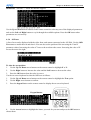
Press the keypad button on the remote control to display the on-screen keyboard.
Keypad button
4. Use the Arrow buttons to highlight the letters you need for your text and press the OK button to
choose them.
56
Chapter 4: IR Remote Control Operation
5.
6.
When your text is complete, press the Keypad button to remove the on-screen keyboard.
Press the OK button to save the new text.
4.3.7 TCP/IP
Use the TCP/IP menu to set the IP address of the AP-5004, the gateway, the subnet mask, the DNS server
IP address, and the HTTP port. If you want to use the AP-5004 on your network, see your network
administrator to obtain a valid IP address for the AP-5004.
Note: when you setup server name and workgroup, please key-in English characters or numbers
only.
To change the TCP/IP parameters:
1. Select the field to change using the Up and Down arrow buttons.
2.
3.
Press the Right arrow button to confirm.
Use the number pad on the remote control to enter a new value
4.
Press the OK button to confirm the new value.
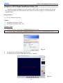
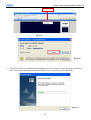
Network Neighbor function:
User can see AP-5004 recording directory from other PC through Microsoft Windows network neighbor.
Then user can copy files in that directory to PC or do remote back up automatically, if user has the proper
software installed on the PC.
After define the server name, workgroup and WINS server, user can find out the AP-5004 recording files
from Microsoft windows network neighbor. See as following picture.
57
Chapter 4: IR Remote Control Operation
4.3.8 Account
Use the Account menu to set up an administrator name and password as well as user name and passwords.
The default administrator name is Webmonitor and the default password is OYO. You can also use this
menu to set up to 16 additional users, their passwords and their permissions on the system.
Note: It is important that you set up a user name and password. The user is different from the
administrator and has access to only the video. Use the More Users function to alter the authorities of
users who access the AP-5004 from the Internet.
To set an Admin/User name or password:
1. Use the Up and Down arrow buttons to select the field to change.
2.
3.
4.
5.
6.
Press the Right arrow button to confirm.
Press the Key Pad button on the remote control to display the on-screen keyboard.
Use the Arrow buttons to select the letters you require and the OK button to confirm.
When the field is correct, press the Key Pad button to turn off the on-screen keyboard.
Press the OK button to confirm.
To set up additional users and their permission rights:
1. Use the Up and Down arrow buttons to select the More Users choice.
2.
3.
Press the Right arrow button to confirm.
Use the Arrow buttons to select the Name and Pass options and modify these fields in the same
manner as in the previous procedure.
4.
5.
6.
7.
8.
Use the Up and Down buttons to select any cameras from Camera1 through Camera16.
Press the Right arrow to select Yes to allow the user to access and control the selected camera.
Use the Up and Down buttons to select the PTZ option.
Press the Right arrow button to select Yes to enable PTZ control of the selected cameras for the user.
Use the Up and Down buttons to select the Playback option.
58
Chapter 4: IR Remote Control Operation
9.
Press the Right arrow button to select Yes to enable the user to record and play back the signal from
the selected cameras.
10. Use the Up and Down buttons to select the Audio option.
Note: Audio can be disabled for live viewing and playback of recordings using the Audio Disable
function.
11. Press the Right arrow button to select Yes to enable the user to hear the live audio from the selected
cameras.
4.3.9 Audio
Use the Audio menu to set up the audio parameters for the AP-5004. The configurable parameters areas
follow:
• Mic Gain – adjusts the gain of the microphone.
• Speaker – adjusts the speaker output level (volume).
• Mic Timeout – sets the timeout for the microphone.
• Speaker Timeout – sets the timeout for the speakers.
• Self Test (Mic -> Spk) – performs a self-test to ensure correct operation of the microphone and speaker.
• Camera - setup which camera mapping to which audio channels. Audio1 is the audio input from
motherboard. The other audio inputs are from video capture card.
Note: Make sure that audio is enabled when recording signals from the cameras attached to the AP-5004.
To set the audio parameters:
1. Use the Up and Down arrow buttons to select a field to change.
2. Use the Right arrow button to increase the value and the Left arrow button to decrease the value.
3. Press the OK button to confirm.
4. Use the Up and Down arrow buttons to select the Self Test (Mic -> Spk) option.
5. Press the Right arrow button to set the option to on to make sure that the microphone and speaker is
working correctly.
4.3.10 Serial ports
The AP-5004 can be connected to other serial devices such as external modems, GPIO (General Purpose
Inputs and Outputs), Voice Call devices, PTZ cameras, camera control devices, text input devices, or USB
serial ports, using two serial ports - COM1 and COM2. The RS232 standard is used for these ports. Use
the Serial Ports menu to set the following parameters:
59
Chapter 4: IR Remote Control Operation
COM1 Device - selects the type the serial device. You can select external modems, GPIO, voice call
modems, etc.
COM1 Speed - sets the speed (1200 to 115200 bps) for the serial device.
COM1 Flow Control - enables or disables the flow control for the device.
COM1 Data Bits - Sets the number of data bits (6, 7, or 8) for the device.
COM1 Parity - Sets odd or even parity.
COM1 Stop Bits - Sets 1 or 2 stop bits for the device.
To change the serial port parameters:
1. Use the Up and Down buttons to select the field to change.
2. Use the Left and Right arrow buttons to cycle through the available options for that field.
3. Press the OK button when the field is set correctly.
Note:
1. You can use the Prev Page and Next Page buttons on the remote control to toggle between the COM1
menu and COM2 menu.
2. When an optional GPIO module is connected to the serial port, the AP-5004 detects it automatically
and provides GPIO options in the system menu.
4.3.11 System information
Use the System Information option to display the System Information screen and view information
about the boot disk, Flash Size,TCP/IP parameters, the MAC ID of the device, firmware version and date
of installation, model number, and hard disk properties.
4.3.12 Date/Time
Use the Date/Time option to set the year, month, day, hour, minute, second, and time zone in which the
AP-5004 is installed.
To set the time or time zone:
1. Use the Up and Down arrow buttons to select the field to change.
60
Chapter 4: IR Remote Control Operation
2. Use the Left arrow to decrease the value and the Right arrow to increase the value for that field.
3. Press the OK button when the values are set correctly.
Note: The AP-5004 reboots to save the changes, if you modify the time zone.
4.3.13
Alarm
Use the Alarm menu to define what constitutes an alarm condition and how the AP-5004 reacts when
such a condition occurs. You can configure an alarm condition to be generated when motion is detected
by the camera, if the video signal is lost from a camera, if the disk space is too low, if there is a disk error
or if pos event. Once the alarm is generated, you can set the alarm notification through a beep, a message,
a video popup or E-mail.
The Alarm menu has the following submenus:
E-Mail - enables you to set up an E-mail address and verify it is working correctly.
Video Popup (sec) - sets the time for which a camera is displayed on your monitor when an alarm is
generated.
Voice Call – this function is not supported.
Set Action - sets the action that will generate an alarm condition for each camera.
Note: The Voice Call function is not supported.
To enter E-mail details:
1. Select the E-Mail option from the Alarm menu.
2. Press the Right button to confirm. The E-Mail submenu is displayed.
3. In the E-Mail menu, use the Up and Down buttons to select a field from the following:
Addr - Type the name of your mail server. See your network administrator for details about the address of
your mail server.
61
Chapter 4: IR Remote Control Operation
Name - Type your user name.
Pass - Type your password.
Sender - Type the e-mail address of the sender.
Test - Checks the validity of the provided E-mail address by sending E-mail.
5. Press the Right arrow button to confirm your selection.
6. Press the Key Pad button on the remote control to display the on-screen keyboard.
7. Use the Arrow keys to select the letters you need to complete the field and press the OK button to
confirm.
8. When the field is complete, press the Key Pad button to turn off the on-screen keyboard.
9. Press the OK button to save your changes.
Video Popup
Use the Video Popup menu to set up the time period for which the video from the selected camera is
displayed on your screen. The default screen is 20 seconds.
To set the video popup time:
1. Use the Up and Down arrow buttons to select the Video Popup option from the Alarm menu.
2. Use the Left arrow button to decrease the popup time and the Right arrow button to increase the
time
3.
Press the OK button to save your settings.
Set Action
Use the Set Action option to define what action is taken by the AP-5004 when an event occurs. The
following options are available:
Video Lost - generates an alarm when the video from the selected camera is not available.
Disk Space Low - generates an alarm when the disk space is insufficient.
Disk Error - generates an alarm if there is an error while accessing the disk.
POS Event - generates an alarm if there is an error while integrate pos data with video.
To configure events using the Set Action option:
1. Use the Up and Down arrow buttons to select an event from the list.
2. Press the Right arrow button to display the submenu for the event with the following options:
Message - displays a message on screen when the event occurs.
Beep - sounds a beep when the event occurs.
E-Mail - sends an E-mail to the specified address when the event occurs.
Voice Call – this function is not supported.
Video Popup - displays the video from the selected camera on your screen.
3. Use the Up and Down buttons to select the desired action from the following options:
62
Chapter 4: IR Remote Control Operation
4.
5.
Press the Right arrow button for the required action to view the submenu.
After enabling the action, set up the Start and End Hour, Minute, and Second to make the feature
active during the specified time interval of the day. The default settings have the feature enabled
throughout the whole day.
6.
If you selected the E-Mail option as the desired action, you have to set up the recipient of the E-mail,
the subject and the text matter of the E-mail. You can specify which of the 16 cameras status is in the
E-mail.
4.3.14
ISP
If you are connecting to the Internet using dial-up, enter your ISP details using the ISP option from the
System Setup menu. Set up the following options:
Phone No. - enter the telephone number that is dialed by the dial-up modem.
Name - enter the user name of your dial-up account.
Pass - enter the password for your dial-up account.
TCP/IP - set up automatic or manual TCP/IP. If the AP-5004 is connecting through a DHCP server, an IP
address is assigned to it automatically. If you want to set the IP address of the device manually, select the
Manual option.
To enter ISP details:
1.
Use the Up and Down arrow buttons to select a field to change.
2. Press the Right arrow button to confirm.
3. Press the Key Pad button on the remote control to display the on-screen keyboard.
4. Use the Arrow buttons to select letters and numbers from the on-screen keyboard and use the OK
button to confirm.
5.
6.
When the field is correct, press the Key Pad button to turn off the on-screen keyboard
Press the OK button to confirm the new field.
4.3.15 Registry server
The Registry Server menu enables you to set up the registry server for your device. If you are using a
dynamic IP address for the AP-5004, you can set up the device to post its IP address to the APEC registry
server. You can then look up your IP from the MAC address or server name.
To enter Registry Server details:
1. Use the Up and Down arrow buttons to select a field to change.
63
Chapter 4: IR Remote Control Operation
2. Press the Right arrow button to confirm.
3. Press the Key Pad button on the remote control to display the on-screen keyboard.
4. Use the Arrow buttons to select letters and numbers from the on-screen keyboard and use the OK
button to confirm.
5.
6.
When the field is correct, press the Key Pad button to turn off the on-screen keyboard.
Press the OK button to confirm the new field.
4.3.16
Running mode
Use the Running Mode menu to switch between Network Mode and ISP Mode, and between Mouse
Mode and IR Remote Control Mode.
4.3.17
Algorithm
You can change the compression algorithm used by the AP-5004 to record video. The AP-5004 supports
MPEG, JPEG, MJPEG, and H.263 ,MPEG4 algorithms for compression. For the JPEG and MJPEG
algorithms, the video quality is better but the data rate is also high. The H.263 and MPEG4 algorithm
provides a good video quality with low data rate .
To set up the algorithm:
1. Use the Up and Down arrow buttons to select a field to change from the Algorithm menu.
2.
3.
Use the Right and Left arrow buttons to toggle the available options.
Press the OK button when the fields are set correctly.
4.3.18
NTP setup
Use the NTP (Network Time Protocol) Setup function to synchronize the real-time clock on the AP-5004
with the atomic clock. Before using this feature, make sure that the correct date, time and time zone have
been set up. Also make sure that the DNS IP number has been set up under the TCP/IP settings.
The following options are available in the submenu:
Enable - enables the NTP function to synchronize the real-time clock.
Period (Hour) - sets up the time interval after which the time is re-synchronized.
Server - selects the NTP server from several pre-defined choices.
Edit NTP Server - enables you to choose your own NTP server.
64
Chapter 4: IR Remote Control Operation
Test&Save? - tests the server and saves the changes.
To change NTP settings:
1. Use the Up and Down arrow buttons to select a field to change from the NTP menu.
2.
3.
4.
Press the Right button to confirm.
Press the Key Pad button on the remote control to display the on-screen keyboard.
Use the Arrow buttons to select letters from the on-screen keyboard and use the OK button to
confirm.
5.
When the field is set correctly, press the Key Pad button on the remote control to turn off the
on-screen keyboard.
6.
Press the OK button to save changes.
4.3.19 License Setup
There are two ways to grant POS license. One is key-in license key; the other one is plug-in a key-pro. So
if you plug-in a key-pro you don’t need to key in the license number again in the license setup menu. Use
the License menu to key in the license number. ʳ
There are three POS License to three levels:
Level 1: Single POS unit – Can connect ONLY one cash register.
Single POS only one cash register. This level pos function doesn’t need to register.
Level 2. 4 POS units -- Can connect maximum 4 cash registers.
Level 3. Full functions – Can connect maximum 16 cash registers.
4.4 Record setup
Use the Record Setup menu to set all the record options for the AP-5004. There are four Record Setup
submenus - AP-5004, Record Schedule, Motion Detection, GPI Trigger , Text Record and Pre-Alarm.
This section covers each submenu in turn.
65
Chapter 4: IR Remote Control Operation
4.4.1 AP-5004 Setup
Use the AP-5004 menu to set the AP-5004 (Digital Video Recorder) mode. Choose Cyclic Recording to
keep recording on the hard disk continuously. Choose Auto Stop to stop recording when the disk is full.
You can set an alarm to be generated when the hard disk is full and send notification through a beep,
E-mail, or text message.
To change the AP-5004 mode:
1. Select the Mode option from the AP-5004 submenu using the Up and Down arrow buttons on the
remote control.
2.
3.
Use the Left and Right buttons to select either Cyclic Recording, or Auto Stop.
Press the OK button to save changes.
4.4.2 Record schedule
You can set up to 16 record schedules that automatically record at given times and days.
To configure a record schedule:
1. From the Record Schedule menu, pick a schedule to change from the displayed list, using the Up
and Down arrow buttons.
2.
Press the Right button to display the parameters for that schedule.
66
Chapter 4: IR Remote Control Operation
3. Use the Up and Down arrow buttons to select a field to change, from the following options:
Enable -enables the recording schedule.
Mon through Sun - enables recording on the specified days of week.
Start Hour/Minute/Second - sets the exact time when the recording starts.
Stop Hour/Minute/Second - sets the exact time when the recording ends.
Camera 1 through 16 - sets the recording mode for the selected camera. Select Normal Record to record
continuously. Select Motion Detect to record only when motion is detected. Select Text Record to record
only when pos event is detected. Select OFF to disable recording.
Audio - enables recording of sound along with the video signal.
Frame Rate Setup - sets the frame rate for recording. Set Auto Speed to Yes and the device evenly
divides the recording frame rate amongst all cameras. If set to No, you can manually set up the individual
frame rates for each camera.
Weight recording- weight recording is setting special recording frame rate when an alarm of one of
camera was triggered.
4.
5.
6.
Use the Right and Left arrow buttons to change the value of that parameter.
Use the Prev Page and Next Page buttons to move to the previous or next page.
Press the OK button when all parameters are set.
4.4.3 Motion Detection
To set motion detection conditions:
1. Use the Up and Down arrow buttons to select the Motion Detection option from the Alarm menu and
press the OK button.
2. When the motion detection menu appears, uses the Up and Down Arrow buttons to select one of the
following options:
• Enable – configures the motion detection feature for each camera.
• Sensitivity – sets the sensitivity value for detecting motion.
• Set Detect Area – sets the area in the camera’s field of vision over which motion is detected. This
option is displayed only after you set the Enable option to Yes.
• Enable all area – sets the all area is motion detect area.
67
Chapter 4: IR Remote Control Operation
• Disable all area –set no area is motion detect area.
3. Select the Enable field and use the Left and Right arrow buttons to toggle between Yes, to enable the
motion detection feature, and No, to disable it.
4. Select the Sensitivity choice and use the Left/Right arrow buttons to decrease/increase the sensitivity.
We recommend that you keep the sensitivity level to its default setting. If the sensitivity level is
adequate, an orange square is displayed in the upper left-hand corner of the screen when motion is
detected.
5. Select the Set Detect Area option and press the Right arrow button to configure the area as follows:
i. The highlighted area in red is the area monitored by motion detection. Use the Arrow buttons to
move the cursor.
ii. Press the OK button to cut off any areas where you want to disable motion detection. If you want
motion detection enabled in the entire field of vision of the camera, leave the screen completely red.
iii. Press the Cancel button to return to the previous menu when done.
6. Select the Save option and press the OK button to save all your changes.
7. Use the Prev Page and Next Page buttons to move to the motion detection menus for all connected
cameras.
8. Press the OK button when settings are correct. You need to provide E-mail details if you want an
E-mail to be sent when an alarm occurs.
4.4.4 GPI Trigger
Use the GPI Trigger function to enable recording video from specified cameras when triggered by an
external alarm (GPI) connected to the system.
4.4.5 Text Record
1. Use the Up and Down arrow buttons to select the Text Record option from the Alarm menu and press
the OK button.
68
Chapter 4: IR Remote Control Operation
2. When the text record menu appears, Use the number buttons on the remote control to enter a new
value. The minimum record time is 30sec.
3. Press the Right arrow button to confirm.
4. Uses the Up and Down Arrow buttons to select POS Event or Text to record only when POS event
or text was detected.
5. Press the OK button when the value is set correctly.
4.4.6 Pre- Alarm
Use the Pre-Alarm function to determine how many frames are recorded before an alarm event occurs.
Each camera can be set separately and you can record up to 300 frames.
To set the Pre-Alarm frame capture:
1. Use the Up and Down arrow buttons to select Pre-Alarm option from the Record Setup menu.
2. Press the OK button to display the Pre-Alarm menu.
3. Use the Up and Down arrow buttons to select the camera to change from the list.
4. Press the Right arrow button to confirm.
5. Use the number buttons on the remote control to enter a new value.
6. Press the OK button when the value is set correctly.
4.5 Playback
Use the Playback function to display a list of all recordings stored on the AP-5004. Use the Up and
Down arrow buttons to select a recording to play back and press the OK button to confirm. The chosen
69
Chapter 4: IR Remote Control Operation
track is played. Use the Prev Page and Next Page buttons on the remote control to move
between pages.
4.5.1 Playback list
Use the Playback list function to display a list of all recordings stored on the AP-5004 as follows.
1. Use the Up and Down arrow buttons to select a recording to play back. The alarm condition which
caused the file to be recorded is indicated in the list. For instance, in the screen shot shown here, the letter
M next to a file indicates that the file was recorded after motion was detected by the camera. “A”
indicates that the file was recorded after a GPIO event. An asterisk (*) before the date indicates that the
file is locked.
2.
3.
Press the OK button to confirm. The chosen recording is played back.
Press the Display button on the remote control to display various properties of the recorded file. The
date and time of recording are displayed in the upper right corner.
Progress - A one hour time line is displayed at the bottom of the screen with the moving orange line
indicating the status of playback.
Recorded Data - The aqua colored portion is where there is recorded data in that hour . A full blue line
means that the whole hour interval was recorded.
GPI - The screen shows where alarm triggers were generated. The red bar shows the trigger. To move to
70
Chapter 4: IR Remote Control Operation
the next motion detection or alarm trigger event, press the Right/Left arrow buttons.
Motion Detection – The yellow bars represent where motion detection was set off.
Searching for a file:
The AP-5004 playback list can be searched for a specific file. You can conduct the search based on time,
event, or text.
4.5.2 To search for a recorded file:
1. While viewing the play list, press the Menu button to display the menu.
2. Select one of the following options using the Up or Down arrow buttons:
Search by Time - searches the list of recorded files for the specified recording time.
Search by Event - searches the list of recorded files for the specified event such as a GPIO trigger that
occurred within the specified time interval.
Search by Text - searches the list of files recorded with POS information for specified text that was
recorded within the specified time interval.
71
Chapter 4: IR Remote Control Operation
3.
Press the Right arrow button to view the submenu for the selected option.
4. Select each of the options such as Year, Month, Day, and so on using the Up or Down arrows.
5. Modify the settings as required using the Left and Right arrow buttons.
Note: If you select the Search by Event option, choose an event from GPI 1~16. If you choose the
Select by Text option, enter the text using the Key Pad button.
6. Press OK when done to conduct the search.
4.5.3 Locking files
To prevent accidental deletion of recorded files, you can lock a file. This also prevents over-writing of the
file when the recording mode is set to Cyclic.
To lock a file:
1. While viewing the play list, use the Up/Down arrow buttons to select the desired file.
2.
Press the Menu button to display the menu.
3. Select the Lock File! option using the Up or Down arrow buttons:
4. Press the OK button to confirm.
The file is locked and cannot be deleted or over-written. There is an asterisk (*) ahead of the file name. To
unlock a file, follow the same procedure and select the Unlock File! option from the menu.
4.5.4 Backing up the data
If the AP-5004 is equipped with CD/RW, DVD+RW drive, you can back up your recorded files to a CD,
DVD, or USB hard drive.
To back up your data:
1. While viewing the play list , press the Menu button to display the menu.
2. Select the Backup option using the Up or Down arrow buttons.
3. Press the OK button to confirm.
The AP-5004 detects if there is a backup device connected to it and starts backing up data.
72
Chapter 4: IR Remote Control Operation
Note: The AP-5004 will begin to collect data as soon as the above screens are displayed. When the
required data has been collected, the backup can begin.
4.6 System Maintenance
Press the Menu button on the remote control to display the main menu on screen. Use the Up and Down
arrow buttons to select one of the five options and press the OK button to confirm your choice.
4.6.1 Alarm log
Any alarm will be written into alarm log include video loss, disk error….etc. User can search alarm log
by specific time.
1. Press “ok” button on “alarm log” option
2. There are many ways to quickly reach alarm log information. Include search by time, directly list all
log, or only GPI, GPO or motion triggered log….
3. After selected one of the searching way, user can see the log and press “ok” button to enter submenu
to get more detail information of log.
73
Chapter 4: IR Remote Control Operation
4.6.2 System log
Any operation will be written into system log include local operation and remote operation. User can
search system log by specific time.
4.6.3 Default settings
Use the Default Settings option to reset all configurable parameters to their factory default settings.
When the Default Settings option is chosen from the System Setup menu, a message is displayed asking
you to confirm. Press the OK button to confirm, or the Cancel button to cancel the operation.
4.6.4 Configuration file
User can backup or restore system configuration values to or from a file. Use Up and Down arrow buttons
to select either Backup or Restore Configuration.
74
Chapter 4: IR Remote Control Operation
4.6.5 Revise firmware
Use the Revise Firmware option to upgrade the firmware in the AP-5004. The firmware can be revised
through an external read-write CD drive, a USB flash drive, or a USB thumb drive. Connect the device to
the AP-5004 and then use this option.
4.7 System Shutdown
Use the System Shutdown option to shut down or reboot the system. To shut down or reboot the system:
1. Use the Up and Down arrow buttons to select either Shutdown or Reboot.
2.
Press the OK button to confirm.
3. Press the OK button to confirm the operation again, or press the Cancel button to cancel the
operation.
75
Chapter 5: APEC Network Operation
Chapter 5. APEC Network Operation
5.1 Introduction
AP-5004 can also be configured over a network using a PC running standard web browser. This
chapter covers network operation. Before you can access AP-5004 from remote PC client, you need to
install DCS Plug-in software. This is a one time effort. Please refer to Chapter 6 for how to install it.
5.2 Connecting
The AP-5004 GUI can be viewed from a Windows IE browser when the device is connected on the same
network as your PC or if it is connected through a cable or xDSL modem to the Internet. Refer to the
hardware manual for more information about making connections using the RJ-45 Ethernet (LAN) port.
Make sure that the AP-5004 is configured for Network running mode.
To access the AP-5004 from remote browser:
1. Open a browser window on a terminal that has network access to the AP-5004.
2. Type the IP address of the AP-5004 in the browser address bar.
Default User Name: webmonitor
Default Password: oyo
Fig. 5-1
If everything is OK, you will get the image of Fig. 5-5 on your VGA screen.
playback button
Fig. 5-5
76
Chapter 5: APEC Network Operation
5.3 Surveillance screen panel
1
4
9
16
split windows select
Group sequencing
Fig. 5-6
The split windows selection icons are there for your selection to show the camera videos
on local screen. It can be 1/4/9/16 splits. The group sequencing icons are for changing camera
videos shown on the local screen in grouping sequence.
5.4 Playback button
Click the Playback button on Fig. 5-7 to playback record files. Please refer to section 5.12 for
detail operations.
Playback button
set up
Fig. 5-7
5.5 Remote PTZ control
When click the single split window button on Surveillance Screen Panel as of Fig. 5-6, if that
camera is configured as PTZ camera, then, the remote PTZ control screen will be brought up as Fig. 5-9.
The numbers from 1 to 16 are for “PRESET” & “RECALL” selection. There are also buttons for “IRIS”,
“ZOOM” and “FOCUS” adjustments. The 4 red arrows at in the bottom circle are for camera movement
control. The yellow dot is for moving speed control.
77
Chapter 5: APEC Network Operation
middle speed
Click to bring up advanced
PTZ functions as Fig. 5-9-1
camera
select
snapshot
full screen
audio
Fig. 5-9
5.5.1 Advanced PTZ function
Fig. 5-9-1 is the screen for Pelco D type PTZ control. You can do “Auto Pan”, “Patrol”
Fig. 5-9-1
and open OSD menu, in addition to what you can do on Fig. 5-9 The PTZ functions and screen layout
here is different for different brands.
78
Chapter 5: APEC Network Operation
5.6 System Setup
Click the SETUP button to display the setup screen as Fig. 5-11.
set up
Fig. 5-10
Use the setup screen to change user definable parameters for the AP-5004. Choose a submenu from the
list on the left and click the link to display it.
Fig. 5-11
79
Chapter 5: APEC Network Operation
5.6.1 Camera Setting
Select the camera that you want to adjust from the “Video Source” field. Video standard is NTSC
or PAL selectable. Values of “Brightness”, “Contrast”, “Saturation” and “Hue” are default at “50”.
The “Quality” is set default at “80”, an acceptable level. You can adjust it higher for better quality.
But, please remember, do NOT make it at “100”. Because the quality level higher than 90 makes
little difference to video improvement, but makes the video data size becomes much larger and this
is no good for remote transmission, especially when the network bandwidth is small
select PTZ camera model
Fig. 5-12
The “compression boost” function is ONLY good when H.263 compression is selected. “Video
resolution” can be 320x240 or 640x480. “Auto Gain Control” is good for adjusting video signal
input level automatically. There is no selection for “Watermark” because this function is always
enabled.
You can also configure the camera for PTZ control here. The “Camera Control Device” field is for
PTZ camera model selection. You need also to fill in “Baud Rate” and “PTZ ID”, which need to match
the setting with PTZ camera. The “Timeout” is, when a remote user logs in and gets PTZ control of
this camera, he will have the number of seconds to control this camera. When the time expires, the
control authority will be grand to other users.
The “Re-detect camera” button is used when the camera loses connection. After finish the setting,
click “Done” to save the changes or click “Write To FlashROM” to prevent from configuration lost
after a power off and power on initialization of AP-5004.
5.6.2 Set name & on screen display
Use the Set Names and On-Screen Display page to set server names of AP-5004 and all cameras.
You can also use this page to key in text to be displayed on screen with each camera under the Set
Overlay Text option. Use the x and y fields to position the displayed text. Use Set Time Stamp option to
define the format of the time stamp. And “Time Stamp” has only 6 fixed positions to be located.
80
Chapter 5: APEC Network Operation
Fig. 5-13
5.6.3 Alarm & remote control
The GPI state can be NO(normally open) or NC(normally close). When NO is selected as shown
below, AP-5004 generate alarm if the GPI state changes to “close” by external event. There are maximum
8 GPI and GPO points in a AP-5004 depends on the IO device installed. The state of GPO can be “ON”
or “OFF” . When “OFF” is selected as below, it means the output points are “open” and when “ON”, it
means “close”.
click to make the changes into effect
Fig. 5-14
5.6.4 System configuration
Use the System Configuration page to set the following parameters for the AP-5004.
• Running mode – Select “Network Mode” if AP-5004 is connected to local LAN through its RJ-45
LAN port. Select “ISP Mode”, if it is connected to Internet via dial up telephone.
• TCP/IP setting – This is normally for “Network Mode” only because when “ISP Mode”, the IP, DNS,
Gateway and Subnet Mask are all assigned by Internet Service Provider.
• ISP setting – Fill in for dial-up connection to Internet through telephone line.
81
Chapter 5: APEC Network Operation
This is ONLY good for
compression algorithm
selected as JPEG
when this is checked, AP-5004
will use the TCP/IP settings you
filled in and don’t care about
ISP’s value.
Fig. 5-15
• Account Setting – This is for remote login account set up. Here you can have one administrator
and one user.
• Set Video Compression Algorithm – Selectable MPEG4 / H264 / JPEG / MJPEG here.
• Set IP Registry Host IP Address & Path – This function is good for AP-5004 that is working
at ISP mode or dynamic IP. It directs AP-5004 to do registry at a registry server and then,
remote PC client can access through registry server to find the AP-5004 unit. The URL of
registry server in Formosa21 is http://www.apecdvr.com
URL of registry server or IP address
Fig. 5-16
82
Chapter 5: APEC Network Operation
When you access http://www.apecdvr.com , you will get the screen as Fig. 5-17. You can then
enter the MAC ID or server name of the AP-5004 that you want to search. In this example, we used
server name “DVR” and we did get one machine. You then need to login using proper user name and
password to see the video. Please be noted, it is better to search by MAC ID or using a unique server
name in order to get the machine you really want.
Fig. 5-17
5.6.5 Set user’s authority
Users created here can ONLY login from remote IE browser. You can create up to 256 users
here. Enter user number in the User field. Assign name and password in the respective fields. You can
prevent this user to access the particular cameras by “Disable” it. The authority of PTZ Control and
Playback functions can also be limited when necessary.
83
Chapter 5: APEC Network Operation
enter sequence number here, 1 - 256
list only remote created users
Fig. 5-18
5.6.6 Audio setting
AP-5004 can support ONLY one audio source from mother board or sound card. So, on Fig. 5-19,
the audio source is either “NULL” or “Audio1(MB)”. The “Microphone Gain” and “Speaker Volume”
are for audio signal level adjustment. The “Timeout” fields of Microphone and Speaker Control are the
number of seconds that a remote login user can access the microphone and speaker. The arrow button
on top of Fig. 5-19 is to click for two way audio communication between remote PC client to AP-5004.
After click it, the audio panel is brought up as Fig. 5-20. The green data rate bar indicates that the two
way audio link is established and the transmission speed indicates the bandwidth consumption for this
audio link. You need to click microphone button ON for talking with AP-5004. You can select the audio
source that you want to record with each camera. But for now, there is ONLY one source “Audio1(MB).
84
Chapter 5: APEC Network Operation
microphone ON/OFF
click to stop
click for two
way audio
data rate
transmission
speed
Fig. 5-19
select source
Fig. 5-20
5.6.7 Set serial port
AP-5004 has 2 serial ports built-in. COM1 is RS232, 9 pin D type. COM2 is RS485, 2 pin at the
back panel slot. COM1 is default for modem connection and COM2 for PTZ control. You probably need
to enter modem initialization string for successful modem connection. “Hardware Flow Control” should
be “Disable” for modem device and “Enable” for “PTZ camera control”.
The serial port device can be PTZ Camera Control, GPIO or Data capture, selectable.
key in modem initialization string
here.
drag to select “modem”, “PTZ”,”GPIO”
or “Data capture” device. It is NOT
recommended to select “voice call”
unless you can find a valid modem for
this purpose.
Fig. 5-21
85
Chapter 5: APEC Network Operation
The NETI/O Setting is used only when you have VP-204 connected to this AP-5004. VP-204 is
a RS232 to LAN converter for POS till machine integration with AP-5004. When connect VP-204 to
the same LAN segment of VP-5004, it will detect VP-204 and you can then select it at the “Port” field
of Fig. 5-22. You can have multiple VP-204 units on the LAN. The “Device Type” for VP-204 is
“Data Capture”. The “ID” shows MAC ID of the selected AP-204 and “Status” shows if it is alive on
the LAN.
Fig. 5-22
5.6.8 Set POS
Here you can set up POS overlay text relay with camera. POS text may come from COM ports or
AP-204 RS232 to LAN converters. You can also set POS text font type, color, size , background and
position on the camera screen. The “Clean POS Text” and “POS Text Clean Time” let you clear up POS
text on the camera screen based on the number of seconds you set.
86
Chapter 5: APEC Network Operation
select serial device
to connect with POS machine
select camera for POS text
overlay
select POS machine model
click to browse font
table
after selected, font name
will be put here automatically
Fig. 5-23
5.6.9 System information
Click the System Information link to display the System Information page.
Fig. 5-24
No information on this page is changeable.
5.6.10 Set time and date
87
Chapter 5: APEC Network Operation
Use the Set Time and Date page to set the time and date. Select a time zone from the drop down menu
and enter new local time and date using the keyboard. Click Done when all fields are updated. Click
Undo to revert to original settings. If you change the time zone, the system will reboot.
time zone select
Fig. 5-25
5.6.11 Set NTP server
You can use “Set NTP Server” to configure a NTP (Network Time Protocol) server for
synchronization of AP-5004 internal system clock. Select a server and enable it using the drop down
menus. Enter a time period using keyboard for the period of synchronization. Click Done when all
parameters are entered correctly. Click Undo to revert to original settings.
server select
if you want to use your own NTP
server, key in its URL here
Fig. 5-26
5.6.12 System Log
Any operation will be written into system log include local operation and remote operation. User can
search system log by specific time.
88
Chapter 5: APEC Network Operation
Fig. 5-27
5.6.13 Alarm Log
Any alarm will be written into alarm log including motion triggerǵGPIO triggerǵDisk errorǵVideo loss
ǵPOS event.…..etc. User can search alarm log by specific time and double click one of the alarm log on
the list to play specification-recording data.
Fig. 5-28
5.7 Record Set Up
5.7.1 DVR setup
Use DVR Setup page to set the recording mode to either Auto Stop (stops when disk space runs out)
or Cyclic Recording (overwrites oldest recordings when disk space runs out).
89
Chapter 5: APEC Network Operation
Fig. 5-29
5.7.2 Record schedule
You can set up max. 16 record schedules here. The combination of the schedules are in “OR”
rule. For example, if you set a camera to record on Monday 13:00 to 16:00 at schedule#1 and at
schedule#2, you set this camera to record on Monday also, from 09:00 to 12:00. If you enable both
these two schedules, then, this camera will record on Monday, from 09:00 to 16:00.
If you set “Start Time” and “Stop Time” both at “00:00:00”, that means always recording to AP-5004.
You can select the recording criteria of each camera from following conditions:
1. Normal Recording – record continuously
2. Motion Detection recording – Record when motion trigger
3. GPI trigger recording – Record when GPI trigger
max. 16 schedule can be set up
when “ON”, camera recording speed is
adjusted by AP-5004 system
Start/Start time all “0” makes it always recording
set up camera recording
speed manually
“ON” for
record audio
Fig. 5-30
Selectable : 1. Normal 2. Motion Detect 3. GPI trigger 4. Motion & GPI 5. Text
4. Motion & GPI trigger Recording – Record when Motion Detection OR GPI trigger
5. Text Recording - Record when POS text received
The recording frame rate of each camera can be configured. But the total number of frame rate adds
up by all cameras can NOT exceed the system frame rate of AP-5004. Please refer to AP-5004
specification for total system frame rate. When configure record frame rate of each camera, you need
90
Chapter 5: APEC Network Operation
to turn “OFF” Auto Speed.
Weight recording is a special feature of APEC machines for efficient use of system resources.
When turn “ON” “Weight rec:” field, the camera that receives event trigger, such as Motion Detection,
or GPI trigger , will record at the frame rate set on “W. RecFPS” field. This function makes cameras
able to record at higher frame rates when something happen and lower frame rate when nothing. This
saves huge storage space, which is an expensive resource of the system. But in any way, the total
number of frame rate can NOT exceed AP-5004 system frame rate. So, if there are too many
concurrent triggers to the cameras, you may not have the exact frame rate you set for weight recording.
5.7.3 GPI Trigger Recording
Click GPI Trigger Recording to bring up Fig. 5-31. There are max. 8 GPI to be selected.
Each GPI trigger can record different cameras. You can set different record time for each GPI. Please
remember to enable the setting and click “Done” after finishing.
5.7.4 POS Text record
When AP-5004 is connected with POS till machine, you can set it up to record when POS text
received. Recording can be ONLY when specific POS text strings which are defined as “POS Event”
or whenever text received based on your selection at Fig. 5-32. Others are the same as Fig. 5-31.
GPI select
click to
bring up
Fig. 5-31
set how many
seconds you want to
record when GPI
triggers
“Yes” to select the cameras
you want to record
Fig. 5-31
91
Chapter 5: APEC Network Operation
select POS event or text. When
POS event, only special text string
defined as “event” triggers the
record. When text, any POS text
received, triggers the record
Fig. 5-32
5.7.5 Set Pre-alarm
You can set each camera to record before alarm happens. The maximum number of frames a
camera can record for “Pre-Alarm” is 300 frames.
set number of frames to
record before alarm trigger
Fig. 5-33
92
Chapter 5: APEC Network Operation
5.8 Alarm Set Up
5.8.1 E-mail set up
AP-5004 can send E-mail with camera snapshots when alarm happens. The alarm includes GPI,
Motion Detection, Video Lost, Disk Space Low, Disk error and POS event. You select from “Type”
field of Fig. 5-34 for the alarm type that you want to send e-mail. The “Start Time” and “Stop Time”
fields for your selection of the time period that you want to send e-mail when alarm. At “To:” field, enter
the destination e-mail address. Check the “Snapshot Camera” boxes for images to attached with the email. The “Global Settings” area is for configuration of mail server data and is common for all kinds
of alarm. You need a mail server account to send mails. The “Interval” field is for the number of seconds
in between two contiguous mails in order NOT to bombard the mail server with too many mails.
5.8.2 POS event set up
When AP-5004 receives text sent from POS till machine, you can define some special text
strings to be “POS Event”. For example, when the string “void” is received, you may consider this
as an abnormal situation and want AP-5004 to generate alarm. This is what POS event used. The
configuration is straight forward as Fig. 5-35
you can define 20 events here
enter text here
Fig. 5-35
93
Chapter 5: APEC Network Operation
selectable GPI, Motion Detection,
Video Lost, Disk Space Low, Disk
error, POS event
destination e-mail
address
Please remember to set up DNS
IP in “System Configuration” if
you use a domain name here in
stead of physical IP
Fig. 5-34
5.8.3 GPO Alarm set up
No need to do anything here.
5.9 Set Motion Detection
The red rectangle in the upper left corner of Fig. 5-35 indicates that motion is being detected. You can
use mouse drag or click the small rectangles one by one to assign the areas that you want to do detection.
Fig. 5-35
94
Chapter 5: APEC Network Operation
5.10 Search
This is the same as Fig. 5-32. Please refer to section 5.6.17, playback.
5.11 FTP Upload
AP-5004 can upload snapshots from the camera using FTP to a predefined location in the event of an
alarm. Use the FTP Upload page to set FTP details.
selectable GPI, Motion
Detection or continuous
when empty, AP-5004 will generate the
file name automatically in following
format :
IP-CH#-yymmddhhnn-xx
If file name is entered, then, AP-5004
will always uses this filename without
change.
Fig. 5-36
Under the Individual Settings, specify the type of event that causes the E-mail to be sent in the Type
field by choosing GPI , Motion Detect or Continuous. Fill in the start and stop time for the period of a
day to do FTP upload. The file name and directory for FTP are also necessary. Enable camera image
snapshot to be uploaded by selecting cameras in the Snapshot option.
ON the Ftp Server field, you can put domain name or IP address. But when domain name is used, you
need to set DNS IP address in System Configuration
The “file name “ field needs to pay particular attention. When it is empty, AP-5004 will generate the file
name automatically in following format : IP-CH#-yymmddhhnn-xx, where “IP” is the IP address of
AP-5004, “CH#” is the channel number of the camera ,”yymmddhhnn” is the year, date, time and “xx”
is the sequential number of that snapshot .If file name is entered, then, AP-5004 will always uses this
filename without change.
5.12 Playback
Click “Playback” to bring up Fig. 5-37 with Fig. 5-38 follows. Click List All to display the entire list.
There are some kinds of search :
1. By calendar – On Fig. 5-37, the yellow block is the date of today. The blue block is the date selected
for listing of record files. On May 8th, there were actually 24 files. We just showed a few of them on
the list.
2. By hour – As on Fig. 5-39, you can input the time you want and then click “Play File” to get the
record files of the date and time selected.
95
Chapter 5: APEC Network Operation
selected for listing on Fig. 5-30
today
Fig. 5-37
select time and click “Play file”
to get the file
Fig. 5-38
Fig. 5-39
click to play
click to bring up Fig. 5-32
3. By search – On Fig. 5-37, click “Search” to bring up Fig. 5-40. You can query by
“Start” / “Stop” time or by POS text. The search based on POS text is a kind of “Transaction”
search. You can define the starting and ending text strings. There are 3 text fields to input
searching strings in a “OR” combination. These features give you “unique” results to find
the records contain the videos of what you really want.
After you get the record file list as Fig. 5-38, click the one you want for play back. Fig. 5-41 is the
play back screen.
POS transaction search. You can input
“Starting” and “Ending” text strings . There
are 3 search text fields in logical “OR”
combination.
select the cameras for text search
Fig. 5-40
96
Chapter 5: APEC Network Operation
see Fig. 5-42
status bar
Fig. 5-41
stop
pause
status bar selection
speed selection
step forward
play
snap shot
save to disk( one camera Only)
On Fig. 5-41, there are some selections:
1. Dimension – You can select 320x240,640x480,800x600,1024x768 to meet the resolution of
your VGA screen.
2. Display – You can select 1/4/8/16 cameras here. This is the number of camera video you want to
show on the screen.
3. Camera – Selection here is related to Display. If you set “16 cameras” at “Display”, then, you
have on choice here only, “ Camera 1-16”. Only when the “Display” filed is set less than 16
cameras, then you have choices here.
4. Bandwidth – Click “Low” or “High” based on your remote connection link speed to AP-5004.
5. Status bar selection – Here you can select “Data”, “Motion”, “GPI” to show different status. On
Fig. 5-33, you see this field is selected as “Data” and the status bar is full of “Blue”. That means
video data was written continuously within this hour. If you select “Motion”, then, you may get
status bar shown up like
. You can see the white gaps among yellow color.
That means, there was NOT always motion detected. Same thing happens to “GPI” selection.
6. Speed selection – You can select playback speed at 1x/2x/4x/full or 1/2x, 1/4x,1/8x.
7. Snapshot – When clicked, the screen will pop up camera selection, you then select the camera
that you want to do snap shot to save the image. File name of the image is assigned automatically
to be “yyyymmddhhmmnnss.jpg”
8. Save to disk – When clicked, you can save the video of a particular camera to disk. You need to
97
Chapter 5: APEC Network Operation
select the camera you want. The file name is automatically created as
“yyyy_mm_dd_hh_mm_ss.d01”.
9. Download & save – Click here to download the entire recording file for save to disk. You can enter
the time slot of interest then click “Download >>>” . File name is default as
“IP-yyyymmddhhmmss.d01”. You can change it. The “From” field counts from the beginning of
that hour and the “To:” field counts from the start of “From:” field.
Fig. 5-42
5.13 Configuration File
Here you can back up the system configuration data of AP-5004 to a file or restore the
configuration data from a file and upload to AP-5004. This function is good for system configuration
back up for multiple machine set up or when abnormal condition occurs, the system manager of AP-5004
can restore previous configured data to the machine.
The operation is straight forward. Select “Backup” and click “Download” to save the configuration
data as a file to hard disk. Select “Restore” and choose the file you want for uploading. See Fig. 5-38.
Fig. 5-43
5.6.24 Back to home page
The Back To Home Page link will redirect you back to the AP-5004 home page.
5.6.25 View video without plug-ins
You can view video even if the machine you are working on does not have the plug-ins necessary for
video monitoring. Click the View Video Without Plug-ins link to view the video page without plugins.
You will need to enter an administrator user name and password to view without plug-ins.
Note: Your browser must be configured to support Java applets to view without plug-ins.
98
Chapter 5: APEC Network Operation
Fig. 5-44
99
Chapter 6: DCS Plugin Installation Guide v3.0
Chapter 6. DCS Plugin Installation Guide v3.0
This DCS plugin will allow us to view remotely APEC DVR’s using IE. Uninstall your current
DCS, apply the patch to the DVR and after that connect to the DVR using IE. It will download and
install the DCS.
Requirements:
PC OS: Windows Xp/Vista
Guides:
Installation in Windows Vista
Installation in Windows XP + IE7
Windows Vista
1.
2.
3.
Login to Windows Vista using an Administrator level account.
If you have DCS / Secuwatch / Secuwatch Client installed in the PC, please uninstall it first.
Open Internet Explorer and key in the IP of the DVR.
4.
5.
Fig. 6-1
It will ask you for the username and password :
It will ask you to install the "dcs.cab" and click on "Install".
Fig. 6-2
100
Chapter 6: DCS Plugin Installation Guide v3.0
Fig. 6-3
Fig. 6-4
6.
The DCS will start to install after downloading the dcs.cab. Please be aware that the download can
take a few minutes depending on the bandwidth of your connection to AP-5004 DVR.
Fig. 6-5
101
Chapter 6: DCS Plugin Installation Guide v3.0
7.
After the installation, you will be able to access remotely the AP-5004 DVR
Fig. 6-6
Windows XP + IE7
1.
2.
3.
4.
Login to Windows XP using a Administrator level account.
If you have DCS / Secuwatch / Secuwatch Client installed in the PC, please uninstall it first.
Open Internet Explorer and key in the IP of the DVR.
It will ask you for the username and password same thing as Fig. 6-7.
Fig. 6-7
5.
It will ask you to install the "dcs.cab" and click on "Install".
click here to install
Fig. 6-8
Fig. 7-8
102
Chapter 6: DCS Plugin Installation Guide v3.0
Click here
Fig. 6-9
Fig. 6-10
6.
The DCS will start to install after downloading the dcs.cab. Please be aware that the download can
take a few minutes depending on the bandwidth of your connection to AP-5004 DVR.
Fig. 6-11
103
Chapter 6: DCS Plugin Installation Guide v3.0
Fig. 6-12
7.
After the installation, you will be able to access AP-5004 DVR remotely.
Fig. 6-13
104
Chapter 7: AP-5004 Moible DVR 3G / GPS configuration
Chapter 7. AP-5004 Mobile DVR 3G / GPS configuration
3G or GPRS communication is important for access AP-5004 mobile DVR from
control center because it is difficult to use Wi-Fi while the vehicle is moving. It is helpful to consult the
document “3G Basic Knowledge” before proceed to do the configuration.
7.1 Requirements
For AP-5004 to work on 3G / GPS , you need the followings available:
3G USB modem
AP-5004 with FW MDVR 2.x
SIM card with 3G service
GPS USB modem
7.2 USB 3G modem support
Firmware 2.X supports USB 3G modem brand & models as follows:
7.2.1 All Huawei models
7.2.2 ZTE MF620 (aka Onda MH600HS), ZTE MF622 (aka Onda MDC502HS) ZTE MF628,ZTE
MF626,ZTE MF628 ,ZTE MF636, ZTE MF638 (aka Onda MDC525UP) ZTE AC8710,
ZTE AC2710,ZTE 6535-Z
7.2.3 ONDA MT503HS, ONDA MT505UP
Γ 7.2.4 AIKO-83D
Γ 7.2.5 ҏNovatel Ovation MC950D,
7.2.6 Merlin XU950D
7.2.7 Ovation 930D
Γ 7.2.8 Novatel U727, ҏNovatel U760 ,
7.2.9 ҏAlcatel One Touch X020 (aka OT-X020, aka MBD-100HU,
aka Nuton 3.5G), ҏAlcatel One Touch X030 (aka OT-X030, aka Nuton NT36HD), ҏAlcatel
X200
7.2.10ΓҏToshiba G450
Γ 7.2.11 ҏUTStarcom UM175 (distributor Alltel)
Γ 7.2.12 Hummer DTM5731
7.2.13 MobiData MBD-200HU
Among these models, we tested
ZTE-MF626
Huawei E156, E220, E176.
When apply 3G service to your local telecom company, please make sure it provides :
Public IP
TCP/IP ports 80 and 4128 are open
Good coverage of 3G, 3.5G and 3.75G
7.3 First step
There are some basic data you need to configure 3G modem. It is easier to install 3G modem on
Windows OS to get the configuration data and in the same time,
make sure the 3G modem works fine under Windows.
When you buy a 3G modem, it comes with an installation software. Install it on a Windows PC.
Following is an example of ZTE MF-626 for reference.
105
Chapter 7: AP-5004 Moible DVR 3G / GPS configuration
Fig. 7-1
After installed, run the software to get the data of “Dial number”, “User name”, “Password”, and
“APN”. If the SIM card uses on the 3G modem has a PIN code, you
need to disable it using this software, as Fig. 7-2
Un-check to disable
Fig. 7-2
7.4 Configure AP-5004
7.4.1 3G modem
Enter “advanced set up “ -> “system configuration” ->”3G” to get Fig. 7-3. Here the “account” &
“password” are the “user name” and “password” are provided by your ISP of 3G service. And you can
select the brand name & model of 3G modem form the “modem” field, as Fig. 7-4.
106
Chapter 7: AP-5004 Moible DVR 3G / GPS configuration
Fig. 7-3
Fig. 7-4
Other fields of Fig. 7-3 are as below:
Baud rate : 921600 by default.
Phone: Phone number to dial. In Taiwan is *99#. It may vary depending on the ISP.
APN: Access Point Name. Provided by ISP. Blank for Taiwan ISP provider.
Boot Connection:
Γ Yes: AP-5004 will try to connect automatically during the startup using 3G modem as configured.
Γ No: It does not connect automatically.
Connect: Click this button to manually start the connection.
Disconnect: Click this button to manually start the disconnection.
Connection Status:
Γ "Connect Failed!": Failed to establish connection.
Γ "ConnectingΞ
Ξ": Connection in progress.
Γ "Connect OK!": Connection successfully established.
Γ "DisconnectingΞ
Ξ": Disconnection in progress.
Γ "Disconnected!": Connection closed.
107
Chapter 7: AP-5004 Moible DVR 3G / GPS configuration
7.4.2 How to check IP address of AP-5004
Enter “System Setup” and click “System info”, then, you can get Fig. 7-5 and see the IP address of
this AP-5004 there.
Fig. 7-5
When AP-5004 connects to Internet through 3G modem, the IP address assigned by ISP will be
dynamic. You will need to use the “registration” function so that the external world can access it from
remote. Please refer to section 5.6.4 for more detail about using “registry”.
AP-5004 needs reporting to its registry server its IP address every certain minutes and we need to change
this value here. Please access AP-5004 through IE browser by
issuing http://IPofDVR/usysvfg.htm , where “IPofDVR” is the IP address of that AP-5004. For
example :
Fig. 7-6
Here “61.222.188.36” is the IP address of APEC demo DVR. Then find the field as below and set it to
one(1) minute.
Default value was “0”.
Fig. 7-7
After that, click “submit” to save the change.
Fig. 7-8
108
Chapter 7: AP-5004 Moible DVR 3G / GPS configuration
7.5 Important notes when using 3G connection
1. Username & Password blank are supported.
2. Make sure that this 3G provider will give you a public IP with port 80, 4128 are unblocked.
3. Disable the PIN of the Sim card, if it has the PIN blocking enabled. You can do this with the
dialing software (for Windows XP) inside the 3G USB Stick.
4. The 3G connection will disconnect the LAN connection.
5. The "LAN" status will become gray as Fig. 7-9 , if the 3G connection is successful.
Fig. 7-9
7.6 How to configure GPS
AP-5004 will search for USB GPS modem ONLY when power on start up. Please make sure to
insert GPS modem on USB port before power on AP-5004.
After AP-5004 boot up into ready, go to “System setup”->”serial port”.
and select the correct USB device (normally it is USB1,if not, please try each one of them).It must be
"USBx", where x is a number.
Fig. 7-10
7.6.1
7.6.2
7.6.3
7.6.4
The setting of other fields are :
Change "Device" to "Data Capture".
Change "Speed" to "4800".
Change "Model" to "GPS".
Change "Show GPS" to "Yes"
Fig. 7-11
109
Chapter 7: AP-5004 Moible DVR 3G / GPS configuration
AP-5004 will reboot after you click “OK”. After reboot, if you are at a place that can receive GPS signals,
you will be able to see the GPS coordinate text at the bottom left of the video window as Fig. 7-12.
Fig. 7-12
7.6.5 GPS USB modem supporting list
Theoretically, all modem that uses Profilic USB-Serial driver is compatible with the firmware of AP5004. Please connect the GPS USB device to Windows, install the driver that comes with the GPS device
and check the "Device Manager". If the GPS device is detected as "Profilic USB-to-Serial Comm Port",
as Fig. 7-13 below, then it should work OK.
Fig. 7-13
The following models were tested OK:
Globalsat BU-353
Gosget BU-363
!!
110
Chapter 7: AP-5004 Moible DVR 3G / GPS configuration
Appendix A: Auto re-connect feature
A.1: Auto re-connect process
Following diagram shows 3G re-connect procedure of AP-5004. This feature will be activated
ONLY if AP-5004 had connected successfully to 3G before the connection broken.
Fig. 7-14
A.2: How to disable auto re-connect feature
When auto-connect feature is activated, and AP-5004 had been connected successfully to 3G, go to
"System Setup ", "3G ", to check its status. If "Connect Status " shows "ReconnectingΞ", as Fig. 7-15,
then click on "ConnectΞ" will disable auto re-connect feature at the next cycle of 3G connection.
111
Chapter 7: AP-5004 Moible DVR 3G / GPS configuration
Fig. 7-15
Appendix B. FAQ
Q1: Can't connect to the 3G network!
A1: Please check these following things:
1. Check if the SIM card is inserted correctly.
2. Check if you SIM card has 3G/GPRS/UTMS service and check if your USB modem can support
that network service.
3. Check the USB modem model & brand.
4. Please check the username / password / APN / Phone Number. Contact your 3G provider
company if you are not sure if these information are correct.
5. The PIN code is disabled? If not, please disable it.
6. Please check if you choose the correct model/brand in "Modem".
Q2: I connected successfully to the 3G network but can't connect remotely using IE.
A2: Please check these following things:
1. Does your 3G network provider provide you with a public IP?
2. Does your 3G network provider block port 80 ?
112