1
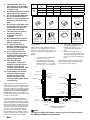
Installation Instructions
ERV/PRV Downdraft Vent
SAVE AND READ THESE INSTRUCTIONS
TESTED IN ACCORDANCE WITH THE LATEST EDITION OF ANSI/UL 858-2001 AND CAN/CSA-C22.2 NO. 64
STANDARD FOR HOUSEHOLD ELECTRIC COOKING AND LIQUID HEATING APPLIANCES.
CONVENTIONS USED IN THESE INSTRUCTIONS
WARNINGS:
Must be followed carefully to avoid personal injury or damage.
NOTES:
Contain helpful hints and tips to facilitate the installation.
IMPORTANT
1.
2.
3.
4.
5.
Before beginning installation, please thoroughly read and become familiar with these instructions.
Installation and service must be completed by a qualified installer or service agency.
Installer: Please leave these Installation Instructions with the owner.
Owner: Please keep these instructions for local electrical inspector’s use and for future reference.
Read the accompanying Use & Care Manual prior to operating this appliance.
TABLE OF CONTENTS
Verifying package contents
Installation planning
Overall dimensions
Electrical power supply requirements
Duct Planning
Cabinet preparation
Installing the ERV
Electrical connection
Cooktop/Range installation
Verifying proper operation
Part No. 65335 Rev. D
Page 2
Page 2
Page 2
Page 2
Pages 2-3
Pages 4-5
Page 5
Pages 5-6
Page 7
Page 7
IMPORTANT SAFETY INSTRUCTIONS
WARNINGS:
1.
Read all instructions before
using the appliance.
13. When cutting or drilling into
wall or ceiling, do not damage
electrical wiring and other
hidden utilities.
3.
Install or locate this appliance
only in accordance with these
installation instructions.
14. Duct fans must always be
vented to the outdoors.
4.
Use this appliance only for its
intended use as described in
this manual.
15. To reduce the risk of fire, use
only metal duct work to install
raised vents.
6.
Do not operate this appliance
if it has a damaged electrical
cord or plug, if it is not
working properly or if it has
been damaged or dropped.
16. For general ventilating use
only. Do not use to exhaust
hazardous or explosive
materials and vapors.
7.
8.
This appliance should be
serviced only by qualified
service personnel. Contact the
nearest DACOR Authorized
Servicer at (800) 772-7778,
or at www.dacor.com for
examination, repair or
adjustment.
Do not cover or block any
openings on the appliance.
10. Do not immerse the electrical
cord or plug in water.
11. Keep the electrical cord away
from heated surfaces.
12. Sufficient air is needed
for proper combustion
and exhausting of gases
through the flue (chimney)
of fuel burning equipment
to prevent back drafting.
Follow the heating equipment
manufacturer’s guideline
and safety standards such
as those published by he
national Fire Protection
Association (NFPA), and
the American Society for
Heating, Refrigeration and
Air Conditioning Engineers
(ASHRAE), and the local code
authorities.
1
17. TO REDUCE THE RISK OF A
RANGE TOP GREASE FIRE:
• Never leave surface units
unattended at high settings.
Boilovers cause smoking and
greasy spillovers that may
ignite. Heat oils slowly on low
or medium settings.
• Always turn hood ON when
cooking at high heat or when
cooking flaming foods.
• Clean ventilating fans
frequently. Grease should not
be allowed to accumulate on
fan or filter.
• Use proper pan size. Always
use cookware appropriate
for the size of the surface
element.
18. TO REDUCE THE RISK OF
INJURY TO PERSONS IN THE
EVENT OF A RANGE TOP
GREASE FIRE, OBSERVE THE
FOLLOWING:
•
SMOTHER FLAMES with a
close-fitting lid, cookie sheet,
or metal tray, then turn off
the burner. BE CAREFUL
TO PREVENT BURNS. If
the flames do not go out
immediately, EVACUATE
AND CALL THE FIRE
DEPARTMENT.
•
NEVER PICK UP A FLAMING
PAN - You may be burned.
•
DO NOT USE WATER,
including wet dishcloths
or towels - a violent steam
explosion will result.
•
Use an extinguisher ONLY if:
• You know you have a Class
ABC extinguisher, and you
already know how to
operate it.
• The fire is small and
contained in the area where
it started.
•
The fire department is
being called.
•
You can fight the fire with
your back to an exit.
Verifying the Package Contents
Installation Planning
• Use and Care manual
• Anchoring Legs
A qualified technician must complete the
installation of this appliance. Proper installation
is your responsibility.
Raised Vent System Specifications
Raised Vent
Model No.
For Use With
For Use with Blower
Duct Size
ERV/PRV30
30” Ranges/Cooktops
REMP3/16, ILB 8/10
3 1/4”x10”, 8” & 10”
ERV/PRV36
36” Cooktops
REMP3/16, ILB 8/10
3 1/4”x10”, 8” & 10”
PRV46
46” Cooktops
REMP3/16, ILB 8/10
3 1/4”x10”, 8” & 10”
ERV48
48” Cooktops
REMP3/16, ILB 8/10
3 1/4”x10”, 8” & 10”
For detailed information on the remote blowers, refer to the Remote Blowers Installation Instructions.
3/4" (19mm) Max. backsplash thickness
1/4" (6mm) Min. flat area
Stud wall
Wall board
2 1/8"
(54mm)
WARNING:
Failure to disconnect power may
result in electrical shock or fire
hazard! If the electric service
provided does not meet the
product specifications, do not
proceed with the installation. Call
the selling dealer or a licensed
electrician.
Electrical Power Supply
Requirements
It is the owner’s responsibility to ensure that
the electrical connection of this appliance
is performed by a qualified electrician. The
electrical installation, including minimum supply
wire size and grounding, must be in accordance
with the National Electric code ANSI/NFPA 701993* (or latest revision) and local codes and
ordinances.
*A copy of this standard may be obtained from:
National Fire Protection Association
1 Batterymarch Park
Quincy, Massachusetts 02269-9101
3"
(76mm)
1 15/16"
(49mm)
9/32" (7mm)
Cooktop/Range
The correct 120VAC, 60Hz, 15A circuit must
be supplied for this appliance from a separate,
grounded, circuit that is protected by a properly
sized circuit breaker or time delay fuse.
2 13/16"
(71mm)
3/8"
(10mm)
“A”
Duct Planning
10"
(254mm)
Countertop
Stiffener
1 7/8" x 16"
Exhaust duct
1.
“B”
6 5/8”
(168mm)
18 13/16”
(478mm)
1 7/8" x 16"
Exhaust duct
25 7/8"
30" (657mm)
(762mm)
3 1/4" x 10"
Rear
Exhaust duct
3 3/4"
(95mm)
3 1/4" x 10"
Exhaust duct
WARNINGS
1 7/8" x 16"
Exhaust duct
6"
(152mm)
Motor
cover
8 1/2"
(216mm)
1 7/8" x 16"
Exhaust duct
ERV Overall Dimensions
Side View
2.
48", 3 prong
grounded
power cord
3/4" (19mm)
Finished floor
Electrical
access panel
3.
ERV Overall Dimensions
Front View
Model
Width “A”
Width “B”
ERV/PRV30
30” (762mm)
27 3/4” (705mm)
ERV/PRV36
36” (914mm)
33 3/4” (857mm)
PRV46
46” (1168mm)
43 3/8” (1102mm)
ERV48
48” (1219mm)
43 3/8” (1102mm)
6"
(152mm)
3" (8mm)
Support Channel
NOTES:
1.
2.
Motor Cover
3/4" (19mm)
CL of ERV/PRV
CL of 1 5/8" x 16" Duct Exhaust
To reduce the risk of fire and
to properly exhaust air, ducted
fans must be vented to outside.
Do not vent exhaust air into
spaces within walls, ceilings,
attics, crawl spaces or garages.
Improper installation,
adjustment, alteration, service,
or maintenance can cause
personal injury or property
damage.
To reduce the risk of fire,
use only ductwork materials
deemed acceptable by state,
municipal and local codes.
3.
Best performance is achieved
by using round duct instead of
rectangular, especially when
elbows are required.
If multiple elbows are needed,
ensure that there is a minimum
of 24” of straight duct between
any two elbows.
Avoid “S” or “back to back”
configurations caused by
adjacent elbows.
ERV/PRV Bottom View
2
4.
5.
6.
7.
8.
9.
10.
11.
12.
13.
14.
Thermal breaks, such as a
short section of non-metallic
duct, should be used in areas
of extreme cold.
A back-draft damper at the duct
outlet may also be required.
Do not use flexible metal duct.
Do not use ductwork that is
smaller in cross-sectional area
than the recommended size
duct.
Do not rely on duct tape alone
to seal duct joints. Use sheet
metal screws as require to
support the duct weight.
The vent hood and cooking
appliance(s) must be
removable if service is
required.
Be certain that the ductwork
does not interfere with floor
joists or wall studs.
It is important to keep a
minimum number of turns in
the duct run, and to keep the
run as short as possible.
Do not restrict the air flow
by reducing the duct crosssectional areas when making
hard joints or squeezing
through a tight area.
With concrete slab
construction, "box-in" the
ductwork to prevent it from
collapsing when the wet
concrete is poured. Also allow
room for electrical conduit.
Cross-drafts or air currents
caused by adjacent open
windows or doors, HVAC
outlets, ceiling fans, and
recessed ceiling lights reduce
vent efficiency.
Higher volumes of air exhausted by the vent
system result in better overall removal of smoke
and fumes from the kitchen. Longer duct runs
and greater numbers of duct transitions reduce
air volume, therefore it is extremely important
to keep duct runs as short and straight as
possible. When longer runs or multiple turns
are unavoidable, and inline blower may be used
to assist the remote blower.
To ensure that your installation meets this
requirement, add the actual straight length of
duct to the equivalent straight length of all duct
fittings to determine the total equivalent straight
length of duct. (Refer to the table above, which
shows various common duct fittings with their
equivalent straight lengths for various common
duct sizes). If this total equivalent straight
length is less than or equal to the maximum
limits specified, then the installation is proper.
Consider the duct size that corresponds to the
majority of the duct used in the installation.
3
Maximum Equivalent Straight Lengths
Model
#
Duct
Size
REMP3
ERV/
PRV
8”
10”
3 1/4”x10”
3 1/4" x 10" 90° Elbow
REMP16
ILB8 w/REMP3
60’
-
50’
-
-
100’
-
140’
50’
60’
50’
100’
3 1/4" x 10" 45° Elbow
3 1/4" x 10" Wall Cap
ILB10 & REMP16
3 1/4" x 10"
90° Flat Elbow
15 Feet
7 Feet
2 Feet
20 Feet
Transistion
3 1/4" x 10" to Round
45° Elbow - Round Duct
90° Transistion
3 1/4" x 10" to 8" Round
90° Elbow - Round Duct
6" Diameter - 4 Feet
7" Diameter - 4 Feet
8" Diameter - 4 Feet
10" Diameter - 4 Feet
6" Diameter - 6 Feet
7" Diameter - 5 Feet
8" Diameter - 3 Feet
10" Diameter - 2 Feet
25 Feet
6" Diameter - 12 Feet
7" Diameter - 10 Feet
8" Diameter - 7 Feet
10" Diameter - 5 Feet
Sample problem:
3.
Given a remote system installation having 25
feet of 3 ¼” x 10” rectangular duct, one (1) 90degree 3 ¼” x 10” elbow, and one (1) 3 ¼” x 10”
to 8” round transition, would this installation be
proper?
Solution:
1.
2.
Add the total length of straight duct:
25’ (of 3 ¼” x 10”) = 25’.
Using Table above, determine the
equivalent straight length of all duct
fittings: 90-degree 3 ¼” x 10” elbow =
15’. 3 ¼” x 10” to 8” round transition =
4’.
4.
Add (1) and (2) to determine the
total equivalent straight length of the
complete duct system: 25’ + 15’ + 4’
= 44’ total equivalent straight duct
length.
For the remote system with 3 ¼” x
10” duct, the maximum allowable total
equivalent straight length of duct is 50
feet. Thus, this proposed installation is
proper.
After determining that your proposed ductwork
meets the maximum duct length requirement,
proceed with the location planning.
Stud wall
Outside wall
REMP3/16
Wall board
3 1/4" x 10"
to round
transition
Countertop
Epicure 36"
Cooktop
Cabinet back
3 1/4" x 10"
Duct
End of ESG
support shelf
ERV36
Supplied
Transition
ATD2 (p/n 13768)
ERV36
Motor cover
Finished floor
Anchoring leg
3 1/4" x 10"
90¼ Elbow
3 1/4" x 10”
to round
transition
3 1/4" x 10"
90¼ Elbow
ILB8/10
ERV Raised Floor Island Installation
with ILB in the Subfloor
NOTE:
The ILB8 and ILB10 Inline Blowers are only approved as a boost assist to
the REMP3 and REMP16 Remote Blowers.
Vertical
non-combustible
surface rear wall
REMP3/16
27 7/8" (708mm)
3/4" (19mm)
Max. backsplash
3 1/4" x 10" to Round
transition
Stud wall
Wall board
27 13/16"
(706mm)
23 3/16"
(589mm)
1/4" (6mm)
Min. flat ledge
2 13/16"
(71mm)
Backsplash
ERV30
3 1/4" x 10"
Duct
Epicure 30
Range
13/16" (21mm)
13/32" (10mm)
29 1/4" (743mm)
30 1/16" (764mm)
Countertop overhangs cabinet
6" (152mm) Min.
to combustible side
walls above the range
3 1/4" x 10"
90¼ Elbow
Anchoring leg
(both sides)
ERV30
Motor cover
ERV/PRV30 with Epicure 30” Range
Slide-In, Self-Rimming Installation
with Side Panels and Backguard Removed
Top View
Finished floor
ERV/PRV Against Wall Installation
with REMP on the Roof
Countertop Preparation
Vertical
non-combustible
surface rear wall
27 7/8" (708mm)
WARNINGS:
1.
2.
3.
To reduce the risk of personal
injury caused by reaching
over a hot appliance, cabinet
storage space located directly
above the cooktop should be
avoided.
Do not store combustible
materials or items adversely
affected by heat in cabinet
areas above the appliance.
Follow the instructions
regarding minimum safe
clearances and installation
location. Failure to do so may
result in a fire or safety hazard.
Plan the installation so that all required minimum
clearances between the cooktop, overhead
cabinets and adjacent vertical walls are
provided. Refer to the cooktop/range installation
instructions for the minimum dimensions specific
to the particular appliance being installed.
The DACOR Raised Vent System is designed
to remove the contaminants and by-products
that result when cooking with gas or electric
appliances. The vent system consists of the vent
intake along with a remote blower and a inline
blower if needed. The raised vent downdraft
systems are compatible for use with select
DACOR cooktops and ranges, therefore, these
instructions offer specific guidelines for mounting
the raised vents behind DACOR cooktops and
ranges.
27 13/16"
(706mm)
Backsplash
thicker than
3/4" (19mm)
1/4" (6mm)
Min. flat ledge
2 13/16"
(71mm)
Adjust for backsplash
over 3/4" thick
from 13/16" to 3 13/16"
(21 - 97mm)
13/32" (10mm)
29 1/4" (743mm)
30 1/16" (764mm)
Countertop overhangs cabinet
6" (152mm) Min.
to combustible side
walls above the range
(both sides)
ERV/PRV30 with Preference 30” Range
Slide-In, Self-Rimming Installation
using 3” Side Panels, Backguard Removed
Top View
Vertical
non-combustible
surface rear wall
28 3/16"
(716mm)
ESG366 -33 7/8" (860mm)
ESG486 - 43 1/2" (1105mm)
21 3/8"
(543mm)
Backsplash
Max.3/4" (19mm)
1/4" (6mm)
Min. flat ledge
2 13/16"
(71mm)
3" (76mm)
5/8" (16mm)
ESG366 - 34 3/4" (883mm)
ESG486 - 46" (1168mm)
ESG366 - 36" (914mm)
ESG486 - 48" (1219mm)
6" (152mm) Min.
to combustible side
walls above the range
(both sides)
ERV with Epicure Cooktops
Top View
4
Dacor
Model No.
Cutout
“A”
Cutout
“B”
CER304
28 1/2”
27 1/2”
CER365
34 1/2”
33 1/2”
ETT304
28 1/2”
27 1/2”
ETT365
34 1/2”
33 1/2”
SGM304
27 1/2”
-
SGM364
33 3/4”
-
SGM365
33 3/4”
-
SGM466
19 7/8”
43 1/2”
SGM464EM
19 7/8”
43 1/2”
Connecting the Exhaust Duct
NOTE:
Use duct tape to seal the
connection between the blower
outlet and duct. Support the duct
weight as necessary to ensure
sealed joints.
For the side or bottom knockouts use the supplied transition. For the rear knockout attach a 3
1/4" x 10" duct.
Electrical Connection
Vertical
non-combustible
surface rear wall
WARNINGS:
Backsplash
Max.3/4" (19mm)
1.
25"
(635mm)
23 1/4"
(591mm)
Min.
22 7/16"
(570mm)
2.
1/4" (6mm)
Min. flat ledge
Flush with
backside of
cabinet front
3.
A
7 1/2" (191mm) Min.
to combustible side
walls above the range
(both sides)
4.
Overall Cutout Dimensions
(SGM304, SGM364, SGM365)
Vertical
non-combustible
surface rear wall
B
25"
(635mm)
23 1/4"
(591mm)
Min.
5.
Backsplash
Max.3/4" (19mm)
19 7/8"
(505mm)
1/4" (6mm)
Min. flat ledge
Flush with
backside of
cabinet front
A
2 9/16"
(65mm)
7 1/2" (191mm) Min.
to combustible side
walls above the range
(both sides)
Overall Cutout Dimensions
(CER304, CER365, ETT304, ETT365, SGM466, SGM464EM)
NOTE:
Verify that the raised vent and
blower being installed are a
matched pair before beginning the
installation.
For installation of the raised vent system,
provide an opening in the countertop as shown
in the Countertop Preparation section. Position
the cutout so all required minimum clearances
are met. Make certain that the minimum flat
countertop area meets or exceeds the combined
overall width and overall depth, as shown.
5
Installing the ERV
NOTE:
The vent must be installed in a
vertical orientation. Do not mount
the vent on a slant or angle.
Remove the knockout from the plenum by
cutting the tape and metal cross overs to
remove the insert.
Loosely attach the anchoring legs to the left
and right sides of the plenum using the hex
nuts provided. Place the vent into the rear of
the countertop cutout. Adjust the anchoring leg
height so that the end caps are gently resting on
the counter, then tighten the hex nuts. Secure
the anchoring legs to the cabinet/floor with the
screws provided.
6.
Ensure that the power supply
is disconnected before
proceeding.
Verify that the power supply
matches the ratings found on
the appliance data plate before
proceeding.
The complete appliance must
be properly grounded at all
times when electrical power is
applied.
Do not ground the appliance
with the neutral (white) house
supply wire. A separate
ground wire must be utilized.
If aluminum house supply
wiring is used, splice the
appliance copper wires to the
aluminum house wiring with
special connectors designed
and agency-certified for this
purpose. Follow the connector
manufacturer’s recommended
procedure carefully. Improper
connection can result in a fire
hazard.
Failure to complete electrical
connections properly may
result in a damaged or nonfunctional system. Follow the
wiring diagrams carefully to
ensure a proper installation.
Both vent systems require a properly grounded,
120 VAC, 60 Hz., 15 Amp electrical service.
Max. full line load is 8 amps. Always use a
dedicated circuit. Do not use same circuit that
cooktop is using.
Make all electrical connections between the
vent and blowers, then connect power to the
vent as per the wiring diagrams. Use wire nuts
provided and electrical tape to secure all wiring
connections at the blowers.
ILB
L2
BLK
WHT
N2
WHT
GRN
Gnd
GRN
BLK
ERV/PRV
Gnd
GRN
GRN
Gnd
GRN
WHT
N1
WHT
BLK
L1
BLK
N2
WHT
L2
BLK
120VAC, 60Hz, 15A
Supply power from
dedicated circuit breaker
Wiring of ERV/PRV with ILB
ERV/PRV
GRN
GRN
GRN
WHT
WHT
BLK
120VAC, 60Hz, 15A
48” (1219mm) power cord with
three prong grounded plug
BLK
WHT
BLK
REMP
BLK
WHT
GRN
Wiring of ERV/PRV with REMP
ILB
BLK
L2
BLK
WHT
N2
WHT
GRN
Gnd
GRN
ERV/PRV
Gnd
GRN
GRN
Gnd
GRN
WHT
N1
WHT
BLK
L1
BLK
N2
WHT
L2
BLK
120VAC, 60Hz, 15A
Supply power from
dedicated circuit breaker
J-BOX
REMP
L2
BLK
N2
WHT
Gnd
GRN
Wiring of ERV/PRV/RV with ILB and REMP
6
Cooktop/Range Installation
WARNING:
1.
2.
The cooktops and ranges
have very different installation
requirement. Please make
sure you read the Installation
Instructions for the
accompanying cooktop/range
thoroughly before continuing
the installation process.
After the cooktop/range
has been installed ensure
that the top cap on the vent
intake does not catch on the
back edge of the cooktop/
range when the intake is
lowered. If interference does
occur, adjust the position
of the cooktop by moving
it against the front edge of
the countertop cutout, then
re-secure the cooktop to the
countertop. Also, ensure that
the vent anchoring legs have
been properly secured to the
cabinet base using the screws
provided in the instructions
envelope. Failure to eliminate
interference may result in
permanent damage to the
vent.
Verifying the Operation
WARNINGS:
1.
2.
3.
7
If the vent system is not
operational after completion
of the installation, do not
attempt to repair it. See the
Problem Solving section of the
Use & Care Manual, then call
a qualified service technician
if the system is still not
functional.
Always disconnect the
appliances from the electrical
power when servicing them.
Install the two (2) front filters
and the grill prior to operating
the vent. Refer to the Use &
Care Manual for instructions
regarding filter and grill
installation.
•
•
•
•
Press the top cap up/down switch
once to raise the ERV to its operating
position.
In the up position, turn the variable
speed control switch in both direction
to verify that the blower is operating
correctly.
Turn the variable speed control switch
counter-clockwise to hi-speed and
clockwise to low speed.
Press the top cap up/down switch
once to lower the ERV pinnacle.
NOTES:
8
NOTES:
9
NOTES:
10
Web Site:
www.dacor.com
For a Dealer/Service: (800) 772-7778
Corporate Phone:
(800) 793-0093