1
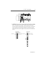
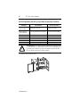
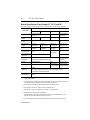
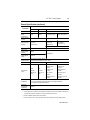
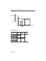
MANUFACTURER DATA SHEET Power Supply Manufacturer: Allen-Bradley/Rockwell Model Number: 1746-P1 See www.geomartin.com for additional PDF datasheets Martin Part Number: VendorPartNumber: E-014624-01 AB # 1746-P1, Power Supply PDF File: Doc_000005_Cover.pdf This page is intentionally left blank SLC 500™ Power Supplies (Catalog Numbers 1746-P1, 1746-P2, 1746-P3, 1746-P4, 1746-P5, 1746-P6, and 1746-P7) Installation Instructions Inside… page Overview . . . . . . . . . . . . . . . . . . . . . . . . . . . . . . . . . . . . . . . . . . . . . . . . . . . . . . . . . . 1 Genéralités . . . . . . . . . . . . . . . . . . . . . . . . . . . . . . . . . . . . . . . . . . . . . . . . . . . . . . . . 13 Deutscher Abschnitt . . . . . . . . . . . . . . . . . . . . . . . . . . . . . . . . . . . . . . . . . . . . . . . . . 25 Istruzioni per l’installazione . . . . . . . . . . . . . . . . . . . . . . . . . . . . . . . . . . . . . . . . . . . . 37 Instrucciones de instalación . . . . . . . . . . . . . . . . . . . . . . . . . . . . . . . . . . . . . . . . . . . 49 Publication 1746-IN004A-ML-P 2 SLC 500™ Power Supplies Important User Information Because of the variety of uses for the products described in this publication, those responsible for the application and use of this control equipment must satisfy themselves that all necessary steps have been taken to assure that each application and use meets all performance and safety requirements, including any applicable laws, regulations, codes and standards. The illustrations, charts, sample programs and layout examples shown in this guide are intended solely for purposes of example. Since there are many variables and requirements associated with any particular installation, AllenBradley does not assume responsibility or liability (to include intellectual property liability) for actual use based upon the examples shown in this publication. Allen-Bradley publication SGI-1.1, Safety Guidelines for the Application, Installation, and Maintenance of Solid-State Control (available from your local Allen-Bradley office), describes some important differences between solid-state equipment and electromechanical devices that should be taken into consideration when applying products such as those described in this publication. Reproduction of the contents of this copyrighted publication, in whole or in part, without written permission of Allen-Bradley Company, Inc., is prohibited. Throughout these installation instructions we use notes to make you aware of safety considerations: ! ATTENTION: Identifies information about practices or circumstances that can lead to personal injury or death, property damage or economic loss. Attention statements help you to: • identify a hazard • avoid the hazard • recognize the consequences Important: Identifies information that is critical for successful application and understanding of the product. Publication 1746-IN004A-ML-P English Section SLC 500™ Power Supplies (Catalog Numbers 1746-P1, 1746-P2, 1746-P3, 1746-P4, 1746-P5, 1746-P6, and 1746-P7) Overview Install your power supply using these installation instructions. The only tools you require are Flat head (1/8”) and Phillips head (1/4”, #2) screwdrivers. ! ATTENTION: Electrostatic discharge can damage integrated circuits or semiconductors if you touch backplane connector pins. Follow these guidelines when you handle the power supplies. • Touch a grounded object to discharge static potential. • Do not touch the backplane connector or connector pins. • Do not touch circuit components inside the power supply. • If available, use a static-safe work station. • When not in use, keep the power supplies in their static-shield packaging. 1746-IN004A-ML-P 4 SLC 500™ Power Supplies Hazardous Location Considerations This equipment is suitable for use in Class I, Division 2, Groups A, B, C, D or non-hazardous locations only. The following WARNING statement applies to use in hazardous locations. WARNING: EXPLOSION HAZARD • Substitution of components may impair suitability for Class I, Division 2. • Do not replace components or disconnect equipment unless power has been switched off or the area is known to be nonhazardous. • Do not connect or disconnect components unless power has been switched off or the area is known to be non-hazardous. • All wiring must comply with N.E.C. article 501-4(b). Environnements Dangereux Cet équipement est conçu pour être utilisé dans des environnements de Classe I, Division 2, Groupes A, B, C, D ou non dangereux. La mise en garde suivante s’applique à une utilisation dans des environnements dangereux. AVERTISSEMENT: DANGER D’EXPLOSION • La substitution de composants peut rendre cet équipement impropre à une utilisation en environnement de Classe I, Division 2. • Ne pas remplacer de composants ou déconnecter l'équipement sans s'être assuré que l'alimentation est coupée. • Ne pas connecter ou déconnecter des composants sans s'être assuré que l'alimentation est coupée. 1746-IN004A-ML-P SLC 500™ Power Supplies 5 Install the Chassis Interconnect Cable (Optional) To connect up to three SLC 500™ chassis together, install the chassis interconnect cable before installing the power supply . SLC 500 chassis/A For more information, see the SLC 500 Modular Style Installation and Operation Manual (publication 1747-6.2). Power Supply Installation 1. Align the circuit board of the power supply with the card guides on the left side of the chassis . 2. Slide the power supply in until it is flush with the chassis. Then fasten the power supply to the chassis . Use these screws to fasten the power supply to the chassis. 1746-IN004A-ML-P 6 SLC 500™ Power Supplies Power Supply Wiring 1. Place the input voltage jumper to match the input voltage. (This does not apply to the 1746-P3, -P5, -P6, and -P7 power supplies, which do not have a jumper.) ! ATTENTION: Set the input jumper before applying power. Hazardous voltage is present on exposed pins when power is applied; contact with the pin may cause injury to personnel. Catalog Number 1746-P1 & -P2 Fuse Catalog Number 1746-P4 Jumper Selection 85-132V ac Jumper Selection 170-265V ac 100/120 Volts 200/240 Volts 2. Connect the ground screw of the power supply to the nearest ground or ground bus. Use a #14 AWG wire and keep the leads as short as possible. The 1746-P4 is shown below. Refer to page 6 for special wiring considerations for the 1746-P3. CHASSIS GROUND Nearest Ground Bus 1746-IN004A-ML-P SLC 500™ Power Supplies 7 3. Connect incoming power. ATTENTION: Turn off incoming power before connecting wires; failure to do so could cause injury to personnel and/or equipment. ! Catalog Number 1746-P1 & P2 Catalog Number 1746-P3 + 24V dc 120/240V ac Incoming Power VAC NEUT Incoming Power Catalog Number 1746-P5 Catalog Number 1746-P4 P4 Jumper Selection DC NEUT CHASSIS GROUND CHASSIS GROUND 85– 132V ac Incoming Power JUMPER +125V dc DC NEUT CHASSIS GROUND 170– 265V ac Catalog Number 1746-P6 L1 85– 132/170– 265 P4 Incoming Power L2 +48V dc NEUTRAL CHASSIS GROUND Incoming Power DC NEUT CHASSIS GROUND Catalog Number 1746-P7 + 12/24V dc Incoming Power DC NEUT CHASSIS GROUND ! ATTENTION: Your SLC 500 power supply can be damaged by voltage surges when switching inductive loads such as motors, motor starters, solenoids, and relays. To avoid damage to your SLC 500 power supply in these applications, it is strongly reccommended than an isolation transformer be used to isolate the power supply from harmful voltage surges. 1746-IN004A-ML-P 8 SLC 500™ Power Supplies 1746-P3 Wiring Considerations The information below describes special wiring considerations for the 1746-P3. ! ATTENTION: Any voltage applied to the 1746-P3 DC NEUT terminal will be present at the SLC logic ground and the processor DH-485 port. To prevent unwanted potentials across the logic ground of the controller and/or damage to the SLC chassis, the DC NEUTRAL of the external DC power source must be either isolated from the SLC chassis ground or connected to earth ground as shown in the following illustration. 1746-P3 External DC Power Source Processor Door DH±485 Port +24V dc +24V dc Earth Ground SLC Logic Ground DC Neut DC Neut Chassis Ground SLC 500 Chassis • A jumper wire is recommended between the DC NEUT and Chassis Ground of the external power source. Earth Ground Important: SLC 500 Series A chassis (1746-A4, -A7, -A10, and -A13) manufactured before November 1992 have a resistor between the logic ground and chassis ground as the drawing on the following page illustrates. This resistor could be damaged if the wiring recommendation described within the attention box above is not followed. See the figure on the following page for the location of the resistor. SLC 500 Series A chassis (1746-A4, -A7, -A10, and -A13) with a manufacture date of November 1992 or later do not have this resistor. SLC 500 Series B chassis have a 1MΩ resistor that limits the current between logic ground and chassis ground. 1746-IN004A-ML-P SLC 500™ Power Supplies 1746-P3 Processor 9 SLC 500 Chassis Door Not Used DH±485 Port Not Used SLC Logic Resistor • Chassis • +24V dc DC Neut Chassis Ground Earth Ground 4. (Optional) For the 1746-P1, -P2,-P4, -P5 and -P6 power supplies, use PWR OUT +24V dc and PWR OUT COM terminals to power 24V dc sensors and loads. The terminals on the 1746-P1, 1746-P2, 1746-P5 and 1746-P6 provide an isolated, nonfused 200 mA, 24V dc power supply. The terminals on the 1746-P4 provide an isolated, nonfused 1A, 24V dc power supply. (The 1746-P3 and -P7 power supplies do not provide for an external power source.) Catalog Number 1746-P1, P2, P5 & P6 User Power PWR OUT +24V dc PWR OUT COM Catalog Number 1746-P4 User Power PWR OUT +24V dc PWR OUT COMMON 1746-IN004A-ML-P 10 SLC 500™ Power Supplies SLC 500 Operation with 24V dc User Power Overcurrent Condition Catalog No. SLC Operation Recovery Procedure 1746-P1 Series A (made in Japan) P/S shutdown, CPU Fault Reload user program 1746-P1 Series A (made in Malaysiacurrent production) 24V dc user shutdown, CPU continues Correct overcurrent condition 1746-P2 Series A, B P/S shutdown, CPU Fault Reload user program 1746-P2 Series C 24V dc user shutdown, CPU continues Correct overcurrent condition 1746-P4 Series A P/S shutdown, CPU Fault Reload user program 1746-P5 Series A 24V dc user shutdown, CPU continues Correct overcurrent condition 1746-P6 Series A 24V dc user shutdown, CPU continues Correct overcurrent condition ! ATTENTION: For 1746-P1 (made in Malaysia), 1746-P2 Series C, 1746-P5 Series A, and 1746-P6 Series A to aviod unexpected operation due to 24V dc user power shutdown, monitor the 24V dc user output with a 24V dc input channel. 5. Remove the protective label. 1746-IN004A-ML-P SLC 500™ Power Supplies 11 Power Supply Undervoltage Operation SLC 500 controllers continue to operate (hold-up) for a short period of time if the input voltage to the power supply drops below the recommended operating voltage range. The controller continues to scan the user program and control I/O during this time. CPU hold-up for each power supply is shown on pages 9 and 10. SLC 500 controllers turn OFF (stop scanning and disable outputs) if input voltage to the power supply is removed or drops below the recommended operating range for a period exceeding the CPU hold-up time. The controller resumes operation automatically when the input voltage is restored to normal. If the input voltage to the 1746-P7 power supply falls into a range of 4 to 9V for a period exceeding the CPU hold-up time, the controller turns OFF and will not turn back ON until: • input voltage is increased to 11V dc. 1746-IN004A-ML-P 12 SLC 500™ Power Supplies General Specifications (Power Supplies P1, P2, P3, and P4) See page 10 for general specifications on the P5, P6, and P7 power supplies. Specification: 1746Description: P1 Line Voltage P2 85-132/170-265V ac 47-63 Hz Typical Line Power 135 VA Reqmnt. 180 VA P3 P4 19.2-28.8V dc 85-132/170-265V ac 47-63 Hz 90 VA 240 VA Maximum Inrush Current 20A Internal Current Capacity 2A at 5V dc 0.46A at 24V dc 5A at 5V dc 0.96A at 24V dc 3.6A at 5V dc 0.87A at 24V dc 10.0A at 5V dc 2.88A at 24V dc1 Fuse Protection 2 1746-F1 or equivalent3 1746-F2 or equivalent4 1746-F3 or equivalent5 Fuse is soldered in place. 45A 24V dc User Power 200 mA Current Capacity 24V dc User Power 18-30V dc Volt. Range 1A1 Not Applicable 20.4-27.6V dc Ambient Operating 0°C to +60°C (+32°F to +140°F) Temperature Current capacity is derated 5% above +55°C. 0°C to +60°C (+32°F to +140°F) no derating Isolation6 None7 2600V dc for 1 s 5 ms (full load) 1000 ms (no load) 20 ms (full load) 3000 ms (no load) 1800V ac RMS for 1 s CPU Hold-up Time8 20 ms (full load) 3000 ms (no load) Certification UL listed C-UL or CSA certified (as indicated by product or packaging markings) CE compliant for all applicable directives Hazardous Environment Cert. Class I Division 2 1. The combination of all output power (5 volt backplane, 24 volt backplane, and 24 volt user source) cannot exceed 70 watts. 2. Power supply fuse is intended to guard against fire hazard due to short-circuit conditions. This fuse may not protect the supply from miswiring or excessive transient in the power line. 3. Equivalent fuses: 250V-3A fuse, nagasawa ULCS-61ML-3, or BUSSMAN AGC 3 4. Equivalent fuse: 250V-3A fuse, SANO SOC SD4, or BUSSMAN AGC 3 5. Equivalent fuse : 125V-3A fuse, Nagasawa ULCS-61ML-5, or BUSSMAN AGC 5 6. Isolation is between input terminals and backplane. 7. No isolation between input terminals and backplane. However, dielectric withstand between input terminals and chassis ground terminal is 600V ac RMS for 1 s. 8. CPU hold-up time is for 0V unless specified. Hold-up time is dependent on power supply loading. 1746-IN004A-ML-P SLC 500™ Power Supplies 13 General Specifications (continued) Specification: 1746Description: P5 Line Voltage Typical Line Power Requirement Maximum Inrush Current P6 P7 90-146V dc 30-60V dc 10-30V dc1 85 VA 100 VA 12V dc input: 50 VA 24V dc input: 75 VA 20A 20A (required for turn-on) Internal Current Capacity 5A at 5V dc 0.96A at 24V dc 12V dc input: 24V dc input: 2.0A at 5V dc 3.6A at 5V dc 0.87A at 24V dc 0.46A at 24V dc See P7 current capacity chart on page 11. Fuse Protection 2 24V dc User Power Current Capacity 24V dc User Power Voltage Range Fuse is soldered in place. Ambient Operating Temp. Isolation3 CPU Hold-up Time4 200 mA Not Applicable 18-30V dc 0°C to +60°C (+32°F to +140°F) Current capacity is derated 5% above +55°C. 1800V ac RMS for 1 s 600V ac RMS for 1 s 12V dc input: 1.37 ms at 0V dc (full load) 20 ms 5 ms 895 ms at 0V dc (full load) (full load) (no load) 3000 ms (no 1500 ms (no 10 ms at 9V dc load) load) (full load) continuous at 9V dc (no load) 24V dc input: 40 ms at 0V dc (full load) 1860 ms at 0V dc (no load) 790 ms at 11V dc (full load) continuous at 11V dc (no load) Certification UL listed C-UL or CSA certified (as indicated by product or packaging markings) CE compliant for all applicable directives Hazardous Environment Certification Class I Division 2 1. See page 11. for information on power supply under voltage operation. 2. Power supply fuse is intended to guard against fire hazard due to short-circuit conditions. This fuse may not protect the supply from miswiring or excessive transient in the power line. 3. Isolation is between input terminals and backplane. 4. CPU hold-up time is for 0V unless specified. Hold-up time is dependent on power supply loading. 1746-IN004A-ML-P 14 SLC 500™ Power Supplies 24V dc Output Current 5V dc Output Current .87A 3.6A 0.625A 2.64A 0.46A 2.0A Input Voltage 10V dc 12.2V dc 19.2Vdc 15Vdc Physical Dimensions Controller: 1746P1 P2 P3 P4 Length: mm (in.) Depth: mm (in.) 65 (2.56) 85 (3.35) 140 (5.70) 110 (4.33) 145 (5.70) 85 (3.35) 140 (5.70) P5 P6 P7 1746-IN004A-ML-P Height: mm (in.) 140 (5.51) 30V dc Publication 1746-IN004A-ML-P - January 2000 40072-083-01 (A) Supersedes Publication 1746-5.1 - Oct 1999 2000 Rockwell International. All Rights Reserved. Printed in USA This page is intentionally left blank