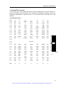
1
Artisan Technology Group is your source for quality
new and certified-used/pre-owned equipment
• FAST SHIPPING AND
DELIVERY
• TENS OF THOUSANDS OF
IN-STOCK ITEMS
• EQUIPMENT DEMOS
• HUNDREDS OF
MANUFACTURERS
SUPPORTED
• LEASING/MONTHLY
RENTALS
• ITAR CERTIFIED
SECURE ASSET SOLUTIONS
SERVICE CENTER REPAIRS
Experienced engineers and technicians on staff
at our full-service, in-house repair center
WE BUY USED EQUIPMENT
Sell your excess, underutilized, and idle used equipment
We also offer credit for buy-backs and trade-ins
www.artisantg.com/WeBuyEquipment
InstraView REMOTE INSPECTION
LOOKING FOR MORE INFORMATION?
Visit us on the web at www.artisantg.com for more
information on price quotations, drivers, technical
specifications, manuals, and documentation
SM
Remotely inspect equipment before purchasing with
our interactive website at www.instraview.com
Contact us: (888) 88-SOURCE | [email protected] | www.artisantg.com
ZT 6650
CompactPCI®
Fast Ethernet® Interface
HARDWARE MANUAL
For ZT 6650 Revision A
ZT M6650
February 25, 1998
10256402
Artisan Technology Group - Quality Instrumentation ... Guaranteed | (888) 88-SOURCE | www.artisantg.com
1050 Southwood Drive
San Luis Obispo, CA 93401 USA
Tel (805) 541-0488
FAX (805) 541-5088
http://www.ziatech.com
Artisan Technology Group - Quality Instrumentation ... Guaranteed | (888) 88-SOURCE | www.artisantg.com
ZT 6650
CompactPCI®
Fast Ethernet® Interface
HARDWARE MANUAL
For ZT 6650 Revision A
ZT M6650
February 25, 1998
10256402
Artisan Technology Group - Quality Instrumentation ... Guaranteed | (888) 88-SOURCE | www.artisantg.com
CompactPCI is a trademark of the PCI Industrial Computers Manufacturers Group.
DEC and Digital Semiconductor are trademarks of Digital Equipment Corporation.
Windows and Windows NT are registered trademarks of Microsoft Corporation.
NWay is a trademark of National Semiconductor Corporation.
QNX is a registered trademark of Quantum Software Systems Ltd.
STD 32 is a registered trademark of Ziatech Corporation.
All other brand and product names are trademarks or registered trademarks of their respective
holders.
© Copyright 1998 Ziatech Corporation.
Artisan Technology Group - Quality Instrumentation ... Guaranteed | (888) 88-SOURCE | www.artisantg.com
WHAT'S IN THIS MANUAL?
This manual describes the operation and use of the ZT 6650 CompactPCI Fast Ethernet Interface.
The following outline summarizes the focus of each chapter in this manual.
Chapter 1, "Introduction," offers an overview of the ZT 6650. It includes a product definition and a
listing of product features. This chapter is most useful to those who wish to compare the features of
the ZT 6650 against the needs of a specific application.
Chapter 2, "Getting Started," summarizes the information you need to get your ZT 6650
operational, including system requirements and connector descriptions. This may be all the
information you need to begin using the ZT 6650.
Chapter 3, "Functional Blocks," illustrates functional relationships between key components of the
board. Some of the topics discussed include compliance levels, software support, features and
registers, and board configuration.
Appendix A, "Specifications," contains the electrical, mechanical, and environmental specifications
for the ZT 6650.
Appendix B, "Customer Support," offers technical support information and instructions for
returning the ZT 6650 if service is necessary.
Artisan Technology Group - Quality Instrumentation ... Guaranteed | (888) 88-SOURCE | www.artisantg.com
This text is intentionally white (it forces a "blank" page to appear in this position in the .PDF file).
Artisan Technology Group - Quality Instrumentation ... Guaranteed | (888) 88-SOURCE | www.artisantg.com
CONTENTS
CHAPTER 1. INTRODUCTION ............................................................................................................. 1
PRODUCT DEFINITION ........................................................................................................... 1
FEATURES OF THE ZT 6650................................................................................................... 1
CHAPTER 2. GETTING STARTED ....................................................................................................... 3
UNPACKING ............................................................................................................................. 3
WHAT'S IN THE BOX? ............................................................................................................. 3
SYSTEM REQUIREMENTS...................................................................................................... 3
HARDWARE INSTALLATION................................................................................................... 4
Connectors ................................................................................................................... 4
Jumpers........................................................................................................................ 4
SOFTWARE DRIVER PACKAGE............................................................................................. 4
CHAPTER 3. FUNCTIONAL BLOCKS.................................................................................................. 5
CompactPCI INTERFACE......................................................................................................... 6
CONNECTIVITY........................................................................................................................ 6
COMMON TRANSFORMER..................................................................................................... 6
PHYSICAL LAYER .................................................................................................................... 6
ETHERNET: DEC21140A ......................................................................................................... 7
Configuration Registers................................................................................................ 8
Command and Status Registers .................................................................................. 9
APPENDIX A. SPECIFICATIONS........................................................................................................ 11
ELECTRICAL SPECIFICATIONS ........................................................................................... 11
ENVIRONMENTAL SPECIFICATIONS .................................................................................. 11
MECHANICAL SPECIFICATIONS.......................................................................................... 11
Board Dimensions and Weight................................................................................... 11
Connectors ................................................................................................................. 12
J1 (CompactPCI Connector)................................................................................ 13
J2 (RJ-45 Connector) .......................................................................................... 14
APPENDIX B. CUSTOMER SUPPORT .............................................................................................. 15
REVISION HISTORY .............................................................................................................. 15
TECHNICAL ASSISTANCE .................................................................................................... 15
RELIABILITY ........................................................................................................................... 15
RETURNING FOR SERVICE.................................................................................................. 15
ZIATECH 5+5 WARRANTY .................................................................................................... 16
Five Year Limited Warranty........................................................................................ 16
Special Extended Warranty Option ............................................................................ 17
Life Support Policy...................................................................................................... 17
Artisan Technology Group - Quality Instrumentation ... Guaranteed | (888) 88-SOURCE | www.artisantg.com
Contents
Artisan Technology Group - Quality Instrumentation ... Guaranteed | (888) 88-SOURCE | www.artisantg.com
TABLES
Connector Assignments ......................................................................................................................... 4
Configuration Registers Mapping ........................................................................................................... 8
Command and Status Registers Mapping.............................................................................................. 9
J1 PCI Interface Pinout......................................................................................................................... 13
J2 (RJ-45 Connector) Pinout................................................................................................................ 14
ILLUSTRATIONS
ZT 6650 Functional Block Diagram ........................................................................................................ 5
ZT 6650 Connector Locations .............................................................................................................. 12
Artisan Technology Group - Quality Instrumentation ... Guaranteed | (888) 88-SOURCE | www.artisantg.com
Tables and Illustrations
Artisan Technology Group - Quality Instrumentation ... Guaranteed | (888) 88-SOURCE | www.artisantg.com
CHAPTER 1. INTRODUCTION
This chapter provides a brief introduction to the ZT 6650 CompactPCI™ Fast Ethernet Interface. It
includes a product definition and a listing of product features. You will find unpacking information and
installation instructions in Chapter 2, "Getting Started."
PRODUCT DEFINITION
The ZT 6650 is a fast Ethernet LAN controller for either 10BASE-T or 100BASE-TX data rates
providing a direct interface to the CompactPCI™ local bus. The interface is based on Digital
Semiconductor's™ DEC™21140A PCI Fast Ethernet LAN Controller chip, a single-chip master,
direct memory access (DMA) Fast Ethernet controller set up to minimize host CPU utilization and bus
traffic.
The ZT 6650 interfaces to the host processor by using onchip command and status registers and a
shared host memory area, set up during initialization. This minimizes processor involvement in the
21140A operation during normal reception and transmission. Bus traffic is also minimized by filtering
out received runt frames and by automatically retransmitting collided frames without a repeated fetch
from the host memory.
FEATURES OF THE ZT 6650
• 32-bit bus mastering design allows maximum throughput without loading the host CPU
• Installs easily with plug and play auto-configuration
• Easily visible LEDs indicate 100BASE-TX operation, plus receive and transmit activity
• National Semiconductor's NWay™ auto-negotiation feature determines 10 Mbits/s operation and
100 Mbits/s operation, in either half or full duplex
• Supports full duplex mode for 20 or 200 Mbits/s operation
• 100% compliant with IEEE 802.3 10BASE-T and 802.3u 100BASE-TX Ethernet standards
• Jumperless and switchless operation
• Compliant with CompactPCI specification 1.0
• 132 Mbits/s data transfer rate through the 32-bit PCI bus
• Remote boot ROM socket allows diskless workstation to boot from LAN server
• Five year warranty and free technical support
Artisan Technology Group - Quality Instrumentation ... Guaranteed | (888) 88-SOURCE | www.artisantg.com
Chapter 1. Introduction
2
Artisan Technology Group - Quality Instrumentation ... Guaranteed | (888) 88-SOURCE | www.artisantg.com
CHAPTER 2. GETTING STARTED
This chapter summarizes the information you need to get your ZT 6650 up and running. You should
read this chapter before you attempt to use the board.
UNPACKING
Please check the shipping carton for damage. If the shipping carton and contents are damaged,
notify the carrier and Ziatech for an insurance settlement. Retain the shipping carton and packing
material for inspection by the carrier. Do not return any product to Ziatech without a Return Material
Authorization (RMA) number. Appendix B explains the procedure you should follow to obtain an RMA
number from Ziatech.
WHAT'S IN THE BOX?
After opening the shipping container, check for the following contents:
• The ZT 6650 CompactPCI board
• Anti-static packing material
• On-Line Help disk for the ZT 6650
• Paper version of the ZT 6650 Operating Manual (if ordered)
If any of the above items is missing, contact Ziatech for assistance. Be sure to save the anti-static
packing material for storing or shipping.
WARNING!
Like all equipment utilizing CMOS devices, the ZT 6650 must be protected from static discharge.
Never remove any of the socketed parts except at a static-free workstation.
SYSTEM REQUIREMENTS
The ZT 6650 is designed for CompactPCI bus applications and is therefore mechanically and
electrically compatible with the CompactPCI Bus Specification.
The board requires +5 VDC ±5% at 840 mA maximum, 640 mA typical. The relative humidity must be
less than 95% at 40° C, non-condensing. Refer to Appendix A for additional specifications.
Artisan Technology Group - Quality Instrumentation ... Guaranteed | (888) 88-SOURCE | www.artisantg.com
Chapter 2. Getting Started
HARDWARE INSTALLATION
The ZT 6650 is designed to plug into a CompactPCI card cage. Steps for installing the ZT 6650
board are as follows:
1. Turn off the power to the CompactPCI card cage.
2. Insert the ZT 6650 into the card cage up to the extraction lever. Make sure you are putting the
ZT 6650 into a bus slot that supports a bus master device. These are generally slots 2 through 6.
3. Pull up on the ZT 6650 until the connector seats.
4. Connect the Ethernet Category 5 cable to the RJ-45 connector on the front plate.
5. Power up the system.
6. On the ZT 97123-100 driver diskette provided with the board, refer to the INSTALL.DOC file
appropriate to your operating system and load the appropriate drivers. Default drivers from
Windows® 95, Windows NT™ and possibly other operating systems will not work with the
ZT 6650. Use the drivers on the ZT 97123-100 diskette.
7. Configure your system using the network driver appropriate to your operating system. (This
manual cannot cover all the possible network configurations in which the ZT 6650 may be used).
Connectors
As shown in the "Connector Locations" drawing, the ZT 6650 includes two connectors to interface to
application-specific devices. The "Connector Assignments" table below pairs each connector with its
function.
Connector Assignments
Connector
Function
J1
CompactPCI local bus interface connector
J2
RJ-45 connector
Jumpers
Since the ZT 6650 uses the PCI bus, which supports plug-and-play configuration, there are no
jumper options for the board.
SOFTWARE DRIVER PACKAGE
A software driver installation package is available (ZT 97121-100) to support DOS, Windows 3.1,
Windows 95, and Windows NT users. A QNX® driver will be available soon. Contact QNX for more
information.
4
Artisan Technology Group - Quality Instrumentation ... Guaranteed | (888) 88-SOURCE | www.artisantg.com
CHAPTER 3. FUNCTIONAL BLOCKS
This chapter presents a high-level look at the way the ZT 6650 functions. It is designed to help you
become more familiar with the board. The "ZT 6650 Functional Block Diagram" illustrates the
functional relationship between the key components on the board, and should be referred to as you
read this chapter.
RJ-45
and
100 Mbits
10 Mbits
Common Transformer
or
100 Mbits
10 Mbits
Physical Layer
Ethernet
DEC 21140A
TM
Interface
ZT 6650
ZT 6650 Functional Block Diagram
Artisan Technology Group - Quality Instrumentation ... Guaranteed | (888) 88-SOURCE | www.artisantg.com
Chapter 3. Theory of Operation
CompactPCI INTERFACE
CompactPCI is an adaptation of the Peripheral Component Interconnect (PCI) Specification. It has
been optimized for industrial and/or embedded applications that require a more robust mechanical
form factor than desktop PCI. CompactPCI uses industry standard mechanical components and high
performance connector technologies to provide a system well suited for rugged applications.
CompactPCI provides a system that is electrically compatible with the PCI Specification, allowing low
cost PCI components to be used. CompactPCI is an open standard supported by the PICMG (PCI
Industrial Computer Manufacturers Group), which is a consortium of companies involved in utilizing
PCI for embedded applications.
CompactPCI appeals to customers that require the following capabilities:
• PCI performance
• 32- and 64-bit data transfers
• 8 PCI slots per system
• Industry standard software support
• 3U small form factor (100 mm by 160 mm)
• 6U form factor (233 mm by 160 mm)
• Eurocard packaging
• Wide variety of available I/O
CONNECTIVITY
(J1) is a CompactPCI compatible connector providing a complete 32-bit PCI local bus interface.
(J2) is an RJ-45 connector for use with either 10BASE-T or 100BASE-TX Ethernet LANs. Such use
requires Category 5 UTP cable.
COMMON TRANSFORMER
The ZT 6650 incorporates a design that allows the board to use a single transformer for both
10 Mbits/s and 100 Mbits/s Ethernet signals. By implementing a common transformer, the design is
less complex, has greater reliability, and consumes less power.
PHYSICAL LAYER
National Semiconductor's DP83840 or DP83233 provides auto-detection and switching of 10 Mbits/s
or 100 Mbits/s signals. Using NWay™ auto-negotiation, the adapter senses the hub's speed and sets
the adapter to run at either 10 Mbits/s or 100 Mbits/s in either Half Duplex or Full Duplex mode,
depending on the capabilities of the hub.
Important: Connection to a 100BASE-TX hub for 100 Mbits/s operation requires Category 5
unshielded twisted-pair (UTP) cable. The maximum length from the 100BASE-TX hub to the adapter
is 100 meters. Connection to a 10BASE-T hub for 10 Mbits/s operation requires a Category 3, 4, or
5 UTP cable.
6
Artisan Technology Group - Quality Instrumentation ... Guaranteed | (888) 88-SOURCE | www.artisantg.com
Chapter 3. Theory of Operation
ETHERNET: DEC21140A
The Digital Semiconductor 21140A PCI Fast Ethernet LAN Controller chip supports the peripheral
component interconnect (PCI) bus. Some of the DEC21140A's features are listed below. This list is
followed by two topics providing outlines of the DEC21140A's configuration registers and command
and status registers (CSRs).
For more detailed information about the DEC21140A, refer to the DEC21140A data book, available
from Digital Equipment Corporation at 1-800-332-2717.
• Supports either 10 Mbits/s or 100 Mbits/s network ports
• Provides a standard 10 Mbits/s and 100 Mbits/s MII supporting CAT 5 UTP and shielded twistedpair (STP) cables
• Contains onchip scrambler and PCS for CAT 5 to significantly reduce the cost of 100BASE-T
solutions
• Supports full-duplex operation on both 10 Mbits/s and 100 Mbits/s ports
• Provides internal loopback capability on both ports
• Contains a variety of flexible address filtering modes (including perfect, hash table, inverse perfect,
and promiscuous):
-- 16 perfect addresses (normal or inverse filtering)
-- 512 hash-filtered addresses
-- 512 hash-filtered multicast addresses and one perfect address
-- Pass all multicast
• Contains large independent receive and transmit FIFOs; no additional onboard memory required
• Supports either big or little endian byte ordering for buffers and descriptors
• Supports IEEE 802.3, ANSI 8802-3, and Ethernet standards
7
Artisan Technology Group - Quality Instrumentation ... Guaranteed | (888) 88-SOURCE | www.artisantg.com
Chapter 3. Theory of Operation
Configuration Registers
As shown in the "Configuration Registers Mapping" table, the DEC21140A uses eight configuration
registers for initialization and configuration to identify and query the DEC21140A.
Configuration Registers Mapping
Configuration Register
Identifier
I/O Address Offset
Identification
CFID
00H
Command and Status
CFCS
04H
Revision
CFRV
08H
Latency timer
CFLT
0CH
Base I/O address
CBIO
10H
Base memory address
CBMA
14H
Reserved
18H-38H
Interrupt
CFIT
3CH
Driver area
CFDA
40H
8
Artisan Technology Group - Quality Instrumentation ... Guaranteed | (888) 88-SOURCE | www.artisantg.com
Chapter 3. Theory of Operation
Command and Status Registers
As shown in the "Command and Status Registers Mapping" table, the ZT 6650 has 16 command and
status registers (CSR0 through CSR15) for host communication. The CSRs are mapped in the host
I/O or memory address space and are used for the following purposes:
• Initialization
• Pointers
• Commands
• Status reporting
Command and Status Registers Mapping
Register
Meaning
Offset from CSR Base Address
(CBIO and CBMA)
CSR0
Bus Mode
00H
CSR1
Transmit poll demand
08H
CSR2
Receive poll demand
10H
CSR3
Receive list base address
18H
CSR4
Transmit list base address
20H
CSR5
Status
28H
CSR6
Operation mode
30H
CSR7
Interrupt enable
38H
CSR8
Missed frame counter
40H
CSR9
Serial ROM and MII management
48H
CSR10
Reserved
50H
CSR11
General-purpose timer
58H
CSR12
General-purpose port
60H
CSR13
Reserved
68H
CSR14
Reserved
70H
CSR15
Watchdog timer
78H
9
Artisan Technology Group - Quality Instrumentation ... Guaranteed | (888) 88-SOURCE | www.artisantg.com
Chapter 3. Theory of Operation
10
Artisan Technology Group - Quality Instrumentation ... Guaranteed | (888) 88-SOURCE | www.artisantg.com
APPENDIX A. SPECIFICATIONS
This appendix describes the electrical, environmental, and mechanical specifications of the ZT 6650.
It also includes illustrations of the board dimensions, the ZT 6650 Connector Locations, the J1
CompactPCI Connector, and tables showing the pin assignments for the ZT 6650s connectors.
ELECTRICAL SPECIFICATIONS
Power requirements for the ZT 6650 are shown in the table below.
Power Requirements
Minimum
Typical
Maximum
Supply Voltage, Vcc
4.75 V
5.00 V
5.25 V
Supply Current, Vcc = 5.0 V
310 mA
640 mA
840 mA
ENVIRONMENTAL SPECIFICATIONS
Operating Temperature:
0° to +65° Celsius
Storage Temperature:
40° to +85° Celsius
Relative Humidity:
< 95% at 40° Celsius, non-condensing
MECHANICAL SPECIFICATIONS
The following topics provide specifications for ZT 6650 dimensions and weight, connector locations,
connector descriptions, and connector pinouts.
Board Dimensions and Weight
Dimensions:
6.299" x 3.937" (160 mm x 100 mm)
Height:
Occupies one card slot
Weight:
5.3 oz. (148 g)
Artisan Technology Group - Quality Instrumentation ... Guaranteed | (888) 88-SOURCE | www.artisantg.com
Appendix A. Specifications
Connectors
J2 RJ-45 Connector
ZT 6650
J1 Compact PCI Connector
As shown in the "Connector Locations" drawing, the ZT 6650 includes two connectors to interface
with application-specific devices. The following topics provide complete descriptions and pinouts for
the connectors.
PIN A1
ZT 6650 Connector Locations
12
Artisan Technology Group - Quality Instrumentation ... Guaranteed | (888) 88-SOURCE | www.artisantg.com
Appendix A. Specifications
J1 (CompactPCI Connector)
J1 is a 110-pin 2 mm x 2 mm right-angle female connector providing the PCI local bus interface. J1
provides a complete 32-bit PCI interface. This connnector is CompactPCI compatible. Refer to the
CompactPCI Specification for details. See the "J1 PCI Interface Pinout" table below for the pin
definitions.
J1 PCI Interface Pinout
Pin#
Z
A
B
C
D
E
F
Pin 25
GND
5V
REQ64#
BRSV
3.3V
5V
GND
Pin 24
GND
AD[1]
5V
AD[0]
ACK64#
GND
Pin 23
GND
3.3V
AD[4]
AD[3]
5V
AD[2]
GND
Pin 22
GND
AD[7]
GND
3.3V
AD[6]
AD[5]
GND
Pin 21
GND
Pin 20
GND
AD[12]
GND
Pin 19
GND
3.3V
AD[15]
Pin 18
GND
SERR#
Pin 17
GND
3.3V
3.3V
(2)
V(I/O)
AD[8]
(5)
M66EN
C/BE[0]#
GND
AD[11]
AD[10]
GND
AD[14]
GND
AD[13]
GND
GND
3.3V
PAR
C/BE[1]#
GND
SDONE
SBO#
GND
PERR#
GND
STOP#
LOCK#
GND
GND
TRDY#
GND
AD[16]
GND
C/BE[2]#
GND
AD[9]
Pin 16
GND
DEVSEL#
GND
Pin 15
GND
3.3V
FRAME#
(2)
V(I/O)
(2),(6)
V(I/O)
IRDY#
Pin 14
KEY AREA
Pin 13
Pin 12
Pin 11
GND
Pin 10
GND
AD[21]
GND
3.3V
AD[20]
AD[19]
GND
Pin 9
GND
C/BE[3]#
IDSEL
AD[23]
GND
AD[22]
GND
Pin 8
GND
AD[26]
GND
V(I/O)
AD[25]
AD[24]
GND
Pin 7
GND
AD[30]
AD[29]
AD[28]
GND
AD[27]
GND
Pin 6
GND
REQ#
GND
3.3V
CLK
AD[31]
GND
Pin 5
GND
BRSV
BRSV
RST#
GND
GNT#
GND
Pin 4
GND
BRSV
GND
V(I/O)
INTP
INTS
GND
Pin 3
GND
INTA#
INTB#
INTC#
5V
INTD#
GND
Pin 2
GND
TCK
5V
TMS
TDO
TDI
GND
Pin 1
GND
5V
-12V
TRST#
+12V
5V
GND
Pin#
Z
A
B
C
D
E
F
AD[18]
AD[17]
PIN A1
ZT6650FA-03
13
Artisan Technology Group - Quality Instrumentation ... Guaranteed | (888) 88-SOURCE | www.artisantg.com
Appendix A. Specifications
J2 (RJ-45 Connector)
J2 is an 8-pin RJ-45 connector that supports both 10BASE-T and 100BASE-TX Ethernet LANs. This
requires the use of Category 5 UTP cable. Pin assignments are given in the "J2 (RJ-45 Connector)
Pinout" table.
J2 (RJ-45 Connector) Pinout
Pin #
Signal
Pin 1
TX+
Pin 2
TX-
Pin 3
RX+
Pin 6
RX-
Pins 4 & 5
Unused pair. These pins are terminated on ZT 6650.
Pins 7 & 8
Unused pair. These pins are terminated on ZT 6650.
14
Artisan Technology Group - Quality Instrumentation ... Guaranteed | (888) 88-SOURCE | www.artisantg.com
APPENDIX B. CUSTOMER SUPPORT
This section offers a product revision history, technical assistance for the ZT 6650, and the
necessary information should you need to return your ZT 6650 for repair.
REVISION HISTORY
Revision A - 9/15/96
Revision A is the original production release of the product.
TECHNICAL/SALES ASSISTANCE
If you have a technical question, please call Ziatech's Customer Support Service at the number
below, or e-mail our technical support team at [email protected]. Ziatech also maintains an
FTP site located at ftp.ziatech.com.
If you have a sales question, please contact your local Ziatech Sales Representative or the Regional
Sales Office for your area. Address, telephone and FAX numbers, and additional information is
available at Ziatech's website, located at http://www.ziatech.com.
Corporate Headquarters
1050 Southwood Drive
San Luis Obispo, CA 93401 USA
Tel (805) 541-0488
FAX (805) 541-5088
RELIABILITY
Ziatech has taken extra care in the product design to ensure reliability. The three major ways in which
reliability is achieved are:
1. The product is designed in top-down fashion, utilizing the latest in hardware and software
techniques, so unwanted side effects and unclean interactions between parts of the system are
eliminated.
2. Ziatech tests each board by exercising its functions, burns it in under power, and retests it to
ensure that the infant mortality phase is passed before the product is shipped.
3. Ziatech maintains a lifetime data base on each board. Any negative trends in reliability are
spotted and Ziatech's suppliers are informed and/or changed.
Artisan Technology Group - Quality Instrumentation ... Guaranteed | (888) 88-SOURCE | www.artisantg.com
Appendix B. Customer Support
RETURNING FOR SERVICE
Before returning any of Ziatech's products, you must obtain a Returned Material Authorization (RMA)
number by calling (805) 541-0488. We will need the following information to expedite the return of
your board:
1. Your company name and address for invoicing.
2. Your shipping address and phone number.
3. The ZT 6650 Product I.D. number.
4. If possible, the name of a technically qualified individual at your company familiar with the
observed mode of failure on the board.
If the unit is out of warranty, service is available at a predesignated service charge. Contact Ziatech
for pricing and please supply a purchase order number for invoicing the repair.
Pack the ZT 6650 in anti-static material and ship in a sturdy cardboard box with enough packing
material to adequately cushion the board. Any product returned to Ziatech improperly packed
will immediately void the warranty for that particular product! Mark the RMA number clearly on
the outside of the box before returning.
ZIATECH 5+5 WARRANTY
Ziatech provides a five year limited warranty to its customers with a special extended warranty option.
Ziatech also has an explicit policy regarding the use of Ziatech products in life support systems.
These topics are covered in the following sections.
Five Year Limited Warranty
Products manufactured by Ziatech Corporation are covered from the date of purchase by a five-year
warranty against defects in materials, workmanship, and published specifications applicable to the
date of manufacture. During the warranty period, Ziatech will repair or replace, solely at its option,
defective units provided they are returned at customer expense to an authorized Ziatech repair
facility. Products which have been subjected to misuse, abuse, neglect, alteration, or unauthorized
repair, determined at the sole discretion of Ziatech, whether by accident or otherwise, are excluded
from warranty. The warranty on fans and disk drives is limited to two years, the warranty on flat panel
displays is limited to nine months from date of purchase. Other products and accessories not
manufactured by Ziatech are limited to the warranty provided by the original manufacturer.
Consumable items (fuses, batteries, etc.) and software are not covered by this warranty.
Ziatech Corporation warrants that for a period of ninety (90) days from the date of purchase; the
media on which software is furnished will be free of defects in materials and workmanship under
normal use; and the software contains the features described in the Ziatech price list. Otherwise, the
software is provided "AS IS". This limited warranty extends only to Customer as the original licensee.
Customer's exclusive remedy and Ziatech's entire liability under this limited warranty will be, at
Ziatech's option, to repair or replace the software, or refund the license fee paid therefore
Ziatech may offer, where applicable and available, replacement products; otherwise, repairs requiring
components, assemblies, and other purchased materials may be limited by market availability.
Ziatech assumes no liability resulting from changes to government regulations affecting use of
materials, equipment, safety, and methods of repair. Ziatech may, at its discretion, offer replacement
products.
THE ABOVE WARRANTY IS IN LIEU OF ANY OTHER WARRANTY, WHETHER EXPRESSED,
IMPLIED, OR STATUTORY, INCLUDING, BUT NOT LIMITED TO, ANY WARRANTY FOR
16
Artisan Technology Group - Quality Instrumentation ... Guaranteed | (888) 88-SOURCE | www.artisantg.com
Appendix B. Customer Support
FITNESS OF PURPOSE, MERCHANTABILITY, OR FREEDOM FROM INFRINGEMENT OR THE
LIKE, AND ANY WARRANTY OTHERWISE ARISING OUT OF ANY PROPOSAL,
SPECIFICATIONS, OR SAMPLE.
Ziatech neither assumes nor authorizes any person to assume for it any other liability. The liability of
Ziatech under this warranty agreement is limited to a refund of the purchase price. In no event shall
Ziatech be liable for loss of profits, use, incidental, consequential, or other damage, under this
agreement.
Special Extended Warranty Option
In addition to the standard five-year warranty, Ziatech offers, for a nominal fee, an extended period of
warranty up to five extra years. This extended warranty period provides similar coverage and
conditions as stated above in the five-year limited warranty agreement.
Life Support Policy
Ziatech products are not authorized for use as critical components in life support devices or systems
without the express written approval of the president of Ziatech Corporation. As used herein:
1. Life support devices or systems are devices or systems which support or sustain life, and whose
failure to perform, when properly used in accordance with instructions for use provided in the
labeling, can be reasonably expected to result in a significant injury to the user.
2. A critical component is any component of a life support device or system whose failure to
perform can be expected to cause the failure of the life support device or system, affect its
safety, or limit its effectiveness.
17
Artisan Technology Group - Quality Instrumentation ... Guaranteed | (888) 88-SOURCE | www.artisantg.com
Appendix B. Customer Support
18
Artisan Technology Group - Quality Instrumentation ... Guaranteed | (888) 88-SOURCE | www.artisantg.com
INDEX
-110 BASE-T
Functional Blocks
Physical Layer ........................................................................................................................... 6
Introduction
Features Of The ZT 6650.......................................................................................................... 1
100 BASE-TX
Functional Blocks
Physical Layer ........................................................................................................................... 6
Introduction
Features Of The ZT 6650.......................................................................................................... 1
-Aauto-negotiation and auto-detection
Functional Blocks
Physical Layer ........................................................................................................................... 6
-Bbase I/O address, configuration registers
Functional Blocks
Configuration Registers Mapping Table .................................................................................... 8
base memory address, configuration registers
Functional Blocks
Configuration Registers Mapping Table .................................................................................... 8
board dimensions and weight
Specifications
Board Dimensions And Weight ............................................................................................... 11
Artisan Technology Group - Quality Instrumentation ... Guaranteed | (888) 88-SOURCE | www.artisantg.com
Index
-Ccable
Functional Blocks
Physical Layer ............................................................................................................................ 6
command and status registers
Functional Blocks
Command And Status Registers ............................................................................................... 9
Command and Status Registers Mapping Table ....................................................................... 9
common (single) transformer
Functional Blocks
Common Transformer ............................................................................................................... 6
CompactPCI connector pin locations
Specifications
CompactPCI Connector Pin Locations Illustration ................................................................... 13
CompactPCI Interface
Functional Blocks
CompactPCI Interface ............................................................................................................... 6
Ethernet: DEC21140A ............................................................................................................... 7
Introduction
Product Definition....................................................................................................................... 1
compatibility
Functional Blocks
Connectivity................................................................................................................................ 6
configuration registers
Functional Blocks
Configuration Registers ............................................................................................................. 8
Configuration Registers Mapping Table..................................................................................... 8
connectivity
Functional Blocks
Connectivity................................................................................................................................ 6
connector locations illustration
Specifications
ZT 6650 Connector Locations Illustration ................................................................................ 12
ii
Artisan Technology Group - Quality Instrumentation ... Guaranteed | (888) 88-SOURCE | www.artisantg.com
Index
connectors
Getting Started
Connectors ................................................................................................................................ 4
Specifications
CompactPCI Connector Pin Locations Illustration .................................................................. 13
Connectors .............................................................................................................................. 12
J1 (CompactPCI Connector) ................................................................................................... 13
J1 PCI Interface Pinout Table ................................................................................................. 13
J2 (RJ-45 Connector) .............................................................................................................. 14
J2 (RJ-45 Connector) Pinout Table......................................................................................... 14
ZT 6650 Connector Locations Illustration................................................................................ 12
current, supply
Specifications
Electrical Specifications........................................................................................................... 11
customer support
Customer Support
Overview.................................................................................................................................. 15
Reliability ................................................................................................................................. 15
Returning For Service.............................................................................................................. 15
Revision History....................................................................................................................... 15
Technical Assistance............................................................................................................... 15
Ziatech 5+5 Warranty.............................................................................................................. 16
-DDEC21140A Fast Ethernet LAN Controller chip
Functional Blocks
Configuration Registers ............................................................................................................. 8
Ethernet: DEC21140A ............................................................................................................... 7
Introduction
Product Definition ...................................................................................................................... 1
dimensions
Specifications
Board Dimensions And Weight ............................................................................................... 11
driver area, configuration registers
Functional Blocks
Configuration Registers Mapping Table .................................................................................... 8
driver diskette (ZT 97123-100)
Getting Started
Hardware Installation................................................................................................................. 4
driver package, software (ZT 97121-100)
Getting Started
Software Driver Package........................................................................................................... 4
iii
Artisan Technology Group - Quality Instrumentation ... Guaranteed | (888) 88-SOURCE | www.artisantg.com
Index
duplex mode, half or full
Functional Blocks
Physical Layer ............................................................................................................................ 6
-Eelectrical specifications
Specifications
Electrical Specifications ........................................................................................................... 11
environmental specifications
Specifications
Environmental Specifications...................................................................................................11
Ethernet
Functional Blocks
Configuration Registers ............................................................................................................. 8
Ethernet: DEC21140A ............................................................................................................... 7
Introduction
Product Definition....................................................................................................................... 1
extended warranty option
Customer Support
Special Extended Warranty Option.......................................................................................... 17
-Ffeatures of the ZT 6650
Introduction
Features Of The ZT 6650 .......................................................................................................... 1
functional block diagram
Functional Blocks
ZT 6650 Functional Block Diagram ........................................................................................... 5
functional blocks
Functional Blocks
Overview .................................................................................................................................... 5
-Ggetting started
Getting Started
Overview .................................................................................................................................... 3
iv
Artisan Technology Group - Quality Instrumentation ... Guaranteed | (888) 88-SOURCE | www.artisantg.com
Index
-Hhardware installation
Getting Started
Hardware Installation................................................................................................................. 4
help
Customer Support
Technical Assistance............................................................................................................... 15
host communication
Functional Blocks
Command And Status Registers ............................................................................................... 9
-II/O address offset, configuration registers
Functional Blocks
Configuration Registers Mapping Table .................................................................................... 8
initialization
Functional Blocks
Command And Status Registers ............................................................................................... 9
installation
Getting Started
Hardware Installation................................................................................................................. 4
interface
Functional Blocks
Connectivity ............................................................................................................................... 6
CompactPCI Interface ............................................................................................................... 6
Ethernet: DEC21140A ............................................................................................................... 7
Introduction
Product Definition ...................................................................................................................... 1
Specifications
J1 PCI Interface Pinout Table ................................................................................................. 13
interrupt
Functional Blocks
Configuration Registers Mapping Table .................................................................................... 8
introduction to ZT 6650
Introduction
Overview.................................................................................................................................... 1
Product Definition ...................................................................................................................... 1
v
Artisan Technology Group - Quality Instrumentation ... Guaranteed | (888) 88-SOURCE | www.artisantg.com
Index
isolation
Functional Blocks
Physical Layer ............................................................................................................................ 6
-JJ1 (CompactPCI Connector)
Specifications
J1 (CompactPCI Connector).................................................................................................... 13
J1 PCI Interface Pinout Table .................................................................................................. 13
J2 (RJ-45 Connector)
Specifications
J2 (RJ-45 Connector)............................................................................................................... 14
J2 (RJ-45 Connector) Pinout Table ......................................................................................... 14
jumpers
Getting Started
Jumpers ..................................................................................................................................... 4
-Llatency timer, configuration registers
Functional Blocks
Configuration Registers Mapping Table..................................................................................... 8
life support policy (warranty)
Customer Support
Life Support Policy ................................................................................................................... 17
local bus interface
Functional Blocks
Connectivity................................................................................................................................ 6
-Mmapping
Functional Blocks
Command and Status Registers Mapping Table ....................................................................... 9
Configuration Registers Mapping Table..................................................................................... 8
vi
Artisan Technology Group - Quality Instrumentation ... Guaranteed | (888) 88-SOURCE | www.artisantg.com
Index
mechanical specifications
Specifications
Board Dimensions And Weight ............................................................................................... 11
CompactPCI Connector Pin Locations Illustration .................................................................. 13
Connectors .............................................................................................................................. 12
J1 (CompactPCI Connector) ................................................................................................... 13
J1 PCI Interface Pinout Table ................................................................................................. 13
J2 (RJ-45 Connector) .............................................................................................................. 14
J2 (RJ-45 Connector) Pinout Table......................................................................................... 14
Mechanical Specifications ....................................................................................................... 11
ZT 6650 Connector Locations Illustration................................................................................ 12
-Ooperating temperature
Specifications
Environmental Specifications .................................................................................................. 11
overview
Customer Support
Overview.................................................................................................................................. 15
Functional Blocks
Functional Blocks
Overview.................................................................................................................................... 5
Getting Started
Getting Started
Overview.................................................................................................................................... 3
Introduction
Introduction
Overview.................................................................................................................................... 1
Specifications
Specifications
Overview.................................................................................................................................. 11
-Pphysical layer
Functional Blocks
Physical Layer ........................................................................................................................... 6
pin locations illustration
Specifications
CompactPCI Connector Pin Locations Illustration .................................................................. 13
pinouts
Specifications
J1 PCI Interface Pinout Table ................................................................................................. 13
J2 (RJ-45 Connector) Pinout Table......................................................................................... 14
vii
Artisan Technology Group - Quality Instrumentation ... Guaranteed | (888) 88-SOURCE | www.artisantg.com
Index
power requirements
Specifications
Electrical Specifications ........................................................................................................... 11
product definition
Introduction
Product Definition....................................................................................................................... 1
-Rregisters
Functional Blocks
Command And Status Registers ............................................................................................... 9
Command and Status Registers Mapping Table ....................................................................... 9
Configuration Registers ............................................................................................................. 8
Configuration Registers Mapping Table..................................................................................... 8
reliability
Customer Support
Reliability.................................................................................................................................. 15
requirements
Getting Started
System Requirements................................................................................................................ 3
returning for service
Customer Support
Returning For Service .............................................................................................................. 15
revision history
Customer Support
Revision History ....................................................................................................................... 15
RMA (Returned Material Authorization)
Customer Support
Returning For Service .............................................................................................................. 15
-Ssoftware
Getting Started
Software Driver Package ........................................................................................................... 4
viii
Artisan Technology Group - Quality Instrumentation ... Guaranteed | (888) 88-SOURCE | www.artisantg.com
Index
specifications
Specifications
Connectors .............................................................................................................................. 12
Electrical Specifications........................................................................................................... 11
Environmental Specifications .................................................................................................. 11
J1 (CompactPCI Connector) ................................................................................................... 13
J1 PCI Interface Pinout Table ................................................................................................. 13
J2 (RJ-45 Connector) .............................................................................................................. 14
J2 (RJ-45 Connector) Pinout Table......................................................................................... 14
Mechanical Specifications ....................................................................................................... 11
ZT 6650 Connector Locations Illustration................................................................................ 12
status and command registers
Functional Blocks
Command And Status Registers ............................................................................................... 9
Command and Status Registers Mapping Table ...................................................................... 9
status reporting
Functional Blocks
Command And Status Registers ............................................................................................... 9
storage temperature
Specifications
Environmental Specifications .................................................................................................. 11
supply current
Specifications
Electrical Specifications........................................................................................................... 11
supply voltage
Specifications
Electrical Specifications........................................................................................................... 11
system requirements
Getting Started
System Requirements ............................................................................................................... 3
-Ttechnical assistance
Customer Support
Technical Assistance............................................................................................................... 15
transformer, common (single)
Functional Blocks
Functional Blocks, Common Transformer................................................................................. 6
ix
Artisan Technology Group - Quality Instrumentation ... Guaranteed | (888) 88-SOURCE | www.artisantg.com
Index
-Vvoltage, supply
Specifications
Electrical Specifications ........................................................................................................... 11
-Wwarranty
Customer Support
Life Support Policy ................................................................................................................... 17
Special Extended Warranty Option.......................................................................................... 17
Ziatech 5+5 Warranty .............................................................................................................. 16
what's in the box?
Getting Started
What's In The Box? ................................................................................................................... 3
weight
Specifications
Board Dimensions And Weight................................................................................................ 11
-ZZiatech 5+5 warranty
Customer Support
Life Support Policy ................................................................................................................... 17
Special Extended Warranty Option.......................................................................................... 17
ZT 97121-10 software driver package
Getting Started
Software Driver Package ........................................................................................................... 4
ZT 97123-100 driver diskette
Getting Started
Hardware Installation ................................................................................................................. 4
x
Artisan Technology Group - Quality Instrumentation ... Guaranteed | (888) 88-SOURCE | www.artisantg.com
Artisan Technology Group - Quality Instrumentation ... Guaranteed | (888) 88-SOURCE | www.artisantg.com
1050 Southwood Drive
San Luis Obispo, CA 93401 USA
Tel (805) 541-0488
FAX (805) 541-5088
http://www.ziatech.com
Artisan Technology Group - Quality Instrumentation ... Guaranteed | (888) 88-SOURCE | www.artisantg.com
Artisan Technology Group is your source for quality
new and certified-used/pre-owned equipment
• FAST SHIPPING AND
DELIVERY
• TENS OF THOUSANDS OF
IN-STOCK ITEMS
• EQUIPMENT DEMOS
• HUNDREDS OF
MANUFACTURERS
SUPPORTED
• LEASING/MONTHLY
RENTALS
• ITAR CERTIFIED
SECURE ASSET SOLUTIONS
SERVICE CENTER REPAIRS
Experienced engineers and technicians on staff
at our full-service, in-house repair center
WE BUY USED EQUIPMENT
Sell your excess, underutilized, and idle used equipment
We also offer credit for buy-backs and trade-ins
www.artisantg.com/WeBuyEquipment
InstraView REMOTE INSPECTION
LOOKING FOR MORE INFORMATION?
Visit us on the web at www.artisantg.com for more
information on price quotations, drivers, technical
specifications, manuals, and documentation
SM
Remotely inspect equipment before purchasing with
our interactive website at www.instraview.com
Contact us: (888) 88-SOURCE | [email protected] | www.artisantg.com