1
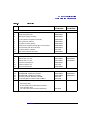
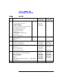
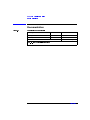
Service Handbook
HP x4000 Workstation
Manufacturing Part Number: A6068-IE002
Edition xxxx
© Copyright 2001 Hewlett-Packard Company.
Legal Notices
The information contained in this document is subject to change without notice.
Hewlett-Packard makes no warranty of any kind with regard to this material,
including, but not limited to, the implied warranties of merchantability and
fitness for a particular purpose.
Hewlett-Packard shall not be liable for errors contained herein or for incidental
or consequential damages in connection with the furnishing, performance, or use
of this material.
Hewlett-Packard assumes no responsibility for the use or reliability of its
software on equipment that is not furnished by Hewlett-Packard.
This document contains proprietary information that is protected by copyright.
All rights are reserved. No part of this document may be photocopied,
reproduced, or translated to another language without the prior written consent
of Hewlett-Packard Company.
Adaptec® is a registered trademark of Adaptec, Inc.
Adobe and Acrobat are trademarks of Adobe Systems Incorporated.
nVIDIA™, GeForce2 GTS™, Quadro2 PRO =and Quadro2 MXR™ are registered
trademarks or trademarks of nVIDIA Corporation.
Matrox® is a registered trademark of Matrox Electronic Systems Ltd.
Microsoft®, Windows®, MS-DOS® and Windows NT® are registered
trademarks of the Microsoft Corporation.
Pentium® and AGPset™ are trademarks of Intel Corporation.
WOL™ (Wake on LAN) is a trademark of IBM.
Rambus, RDRAM, Direct Rambus, Direct RDRAM and RIMM are trademarks of
Rambus, Inc.
Printing History
The manual printing date and part number indicate its current edition. The
printing date will change when a new edition is printed. Minor changes may be
made at reprint without changing the printing date. The manual part number
will change when extensive changes are made.
First Edition: May 2001
Printing Division:
Hewlett-Packard Co.
Technical Computer Division
3404 E. Harmony Rd.
Fort Collins, CO 80525
Printed in the U.S.A.
2
Contents
1. HP x4000 Service Information
Overview . . . . . . . . . . . . . . . . . . . . . . . . . . . . . . . . . . . . . . . . . . . . . . . . . . .6
x4000 System Board . . . . . . . . . . . . . . . . . . . . . . . . . . . . . . . . . . . . . . . . . .7
System Board Switches . . . . . . . . . . . . . . . . . . . . . . . . . . . . . . . . . . . . . .8
BIOS Identification . . . . . . . . . . . . . . . . . . . . . . . . . . . . . . . . . . . . . . . . . . .9
Upgrading Memory . . . . . . . . . . . . . . . . . . . . . . . . . . . . . . . . . . . . . . . . . .10
Replacing or Upgrading a Processor. . . . . . . . . . . . . . . . . . . . . . . . . . . . .13
Removing a Processor . . . . . . . . . . . . . . . . . . . . . . . . . . . . . . . . . . . . . .13
Installing a Processor. . . . . . . . . . . . . . . . . . . . . . . . . . . . . . . . . . . . . . .14
Updating Your Operating System . . . . . . . . . . . . . . . . . . . . . . . . . . . . .16
2. Accessory Ordering Information
Supported Accessories . . . . . . . . . . . . . . . . . . . . . . . . . . . . . . . . . . . . . . . .18
Mass Storage Device Guide Rails . . . . . . . . . . . . . . . . . . . . . . . . . . . . . . .20
3. HP x4000 Parts Information
x4000 Parts and Part Numbers . . . . . . . . . . . . . . . . . . . . . . . . . . . . . . . .22
Documentation. . . . . . . . . . . . . . . . . . . . . . . . . . . . . . . . . . . . . . . . . . . . . .26
Software and Training CDs . . . . . . . . . . . . . . . . . . . . . . . . . . . . . . . . . . .27
3
Contents
4
1
HP x4000 Service Information
Chapter 1
5
HP x4000 Service Information
Overview
Overview
This chapter contains information about:
• “x4000 System Board” on page 7
• “BIOS Identification” on page 9
• “Upgrading Memory” on page 10
• “Replacing or Upgrading a Processor” on page 13
Chapter 2 contains ordering information for x4000 accessories.
Chapter 3 contains ordering information for x4000 parts.
6
Chapter 1
HP x4000 Service Information
x4000 System Board
x4000 System Board
Chapter 1
7
HP x4000 Service Information
x4000 System Board
System Board Switches
The system board includes a 4-pole DIP switch, which lets you configure
BIOS functions. Because the switches are read only at system start up,
you must change the switch positions when the Workstation is shut
down.
Switch
Function
Default
Comment
1
Clear BIOS
password
Off
Clears both Administrator and User
passwords, if they have been set.
2
Boot block
recovery
Off
Forces a boot block recovery from a
bootable BIOS flash disk in the floppy
disk drive.
3
Clear CMOS
Off
Reset CMOS settings to BIOS defaults.
You can also do this with the F9 key in
the Setup program as described in
“Clearing the CMOS” on page 48.
4
Enable safe mode
Off
Force processors to run at 800 MHz. This
can be used as a troubleshooting tool or
to correct a problem after adding a
second processor. Before using this, flash
the BIOS as described at
www.hp.com/workstations/support. Use
this switch as a last resort. If it gets the
system running, replace the processors.
If the problem persists, replace the
system board.
8
Chapter 1
HP x4000 Service Information
BIOS Identification
BIOS Identification
The system BIOS is identified by the version number XX.YM.mm, where:
• XX is a two-letter code indicating the system
• Y is a one-letter code indicating the HP entity
• M is the major BIOS version
• mm is the minor BIOS version
Chapter 1
9
HP x4000 Service Information
Upgrading Memory
Upgrading Memory
The memory for the HP x4000 Workstation is located on a Memory
Expander Card, which plugs into the system board.
There are two memory banks (RDRAM channels):
• Bank I includes sockets 1B (J1), 2B (J2), 1A (J5), and 2A (J6).
• Bank II includes sockets 3B (J3), 4B (J4), 3A (J7), and 4A (J8).
This allows for a total of 8 RIMMs.
You must adhere to the following rules when loading memory:
• RIMMs must be loaded in matched pairs. Matching RIMMs have the
same RDRAM size, speed and Mbit technology.
• Each RDRAM bank (channel) must be either completely empty or
completely filled as shown in Figure 1-2. Therefore, if only one pair of
RIMMs is installed in a bank, then the remaining sockets in the bank
must contain continuity modules (CRIMMs) to ensure continuity.
NOTE
All Workstations (unless they already have 8 RIMMs) ship with a pair of
CRIMMs in case they are needed in future memory configurations.
CRIMMS may be stored in an unused memory bank.
10
Chapter 1
HP x4000 Service Information
Upgrading Memory
Figure 1-1
x4000 Memory Expander Card (MEC)
2A (J6)
1A (J5)
4B (J4)
3B (J3)
4A (J8)
3A (J7)
2B (J2)
1B (J1)
Memory Bank I consists of:
RIMM pair 1: 1A (J5) and 1B (J1)
RIMM pair 2: 2A (J6) and 2B (J2)
Memory Bank II consists of:
RIMM pair 3: 3A (J7) and 3B (J3)
RIMM pair 4: 4A (J8) and 4B (J4)
If a m em ory bank only contains 1 pair of RIMMs, the remaining
2 connectors m ust contain CRIMM s to ensure continuity.
Chapter 1
11
HP x4000 Service Information
Upgrading Memory
Figure 1-2
Replacing or Upgrading Memory
1 Pair of RIMMs
2 Pairs of RIMMs
CRIMM
RIMM 1A
RIMM 2A
RIMM 1A
CRIMM
RIMM 1B
P1 - edge
3 Pairs of RIMMs
RIMM 2B
RIMM 1B
Memory
Bank I
P1 - edge
4 Pairs of RIMMs
RIMM 2A
RIMM 1A
CRIMM
RIMM 3B
RIMM 2A
RIMM 1A
RIMM 4B
RIMM 3B
CRIMM
RIMM 3A
RIMM 2B
RIMM 1B
RIMM 4A
RIMM 3A
RIMM 2B
RIMM 1B
P1 - edge
Memory
Bank II
P1 - edge
Note: RIMM 1A and 1B are a matched pair, 2A and 2B are a matched pair,
3A and 3B are a matched pair, and 4A and 4B are a matched pair.
12
Chapter 1
HP x4000 Service Information
Replacing or Upgrading a Processor
Replacing or Upgrading a Processor
The x4000 Workstation can have two processors. The processors must be
identical.
CAUTION
If you are upgrading your current processor, you must update the BIOS.
The latest BIOS is located at www.hp.com/workstations/support.
If you are adding a second processor, you must update your operating
system (see “Updating Your Operating System” on page 16).
Removing a Processor
CAUTION
Before removing your processor, turn on the Workstation and let it run
for 3 to 5 minutes. This warms up the processor and makes it easier to
detach the heatsink. Be very careful when removing the heatsink. If your
processor turbo cooler fan is not operating, the heatsink may be very hot.
Under normal circumstances, the turbo cooler fan is operational and a
slight twist of the heatsink should release it from the processor.
To remove a processor:
1. Turn off the display and shut down the Workstation. Disconnect all
power cables and any LAN or telecommunications cables.
2. Remove the Workstation’s cover.
3. Place the Workstation on its side for better access.
4. Open the hard disk drive cage.
5. Remove the Chassis Beam Assembly.
6. Remove the MEC card.
7. Remove the heatsink power connector from the system board.
Chapter 1
13
HP x4000 Service Information
Replacing or Upgrading a Processor
8. Remove the two heatsink clips by pressing the release lever on the
clips. Then lift off the heatsink. There is a thermal interface material
between the heatsink and the processor. This may cause the processor
to stick to the heatsink.
Figure 1-3
Removing a Processor
Step 8
Step 10
9. Remove the thermal interface material from the heatsink and discard
it. You can leave any residue that remains on the heatsink. This does
not impair the heat transfer.
10. Open the Zero Insertion Force (ZIF) lever, located at the side of the
processor socket, until it is in the vertical position (depending on the
socket design, the handle may need to go past vertical), then carefully
lift out the processor. To avoid bending the processor pins, keep the
processor perfectly flat when removing it.
11. Store the processor in an anti-static bag (such as the one provided
with the replacement processor).
12. If you are permanently removing a second processor, you must update
your operating system (see page 16). You should also store the
heatsink and clips in a safe place.
Installing a Processor
To install a processor:
1. Turn off the display and shut down the Workstation. Disconnect all
power cables and any LAN or telecommunications cables.
2. Remove the Workstation’s cover.
3. Place the Workstation on its side for better access.
14
Chapter 1
HP x4000 Service Information
Replacing or Upgrading a Processor
4. Open the hard disk drive cage.
5. Remove the Chassis Beam Assembly.
6. Remove the MEC card.
7. Ensure the processor is correctly oriented by matching the notches on
the processor to the notches on the ZIF socket. Then carefully lower
the new processor into place. When the processor is fully inserted,
close the ZIF lever.
CAUTION
Figure 1-4
Be extremely careful when you insert the processor. If you bend one of
the pins, it will not go into the socket.
Inserting a Processor
Step 9
Step 7
8. Affix the new thermal interface material, provided with the new
processor, to the top of the processor.
9. Attach the heatsink to the processor. Use the retaining clips to attach
the heatsink. For easier installation, partially attach both clips by
hooking one end of the side slot in each clip. Press down on the
remaining ends of both clips until they click into place.
10. Connect the heatsink turbo fan power connector to the system board.
The fan connectors are labeled CPU0 and CPU1 on the system board.
11. Replace the MEC card.
12. Replace the Chassis Beam Assembly.
13. Close and secure the hard disk drive cage.
14. Replace the Workstation’s cover.
Chapter 1
15
HP x4000 Service Information
Replacing or Upgrading a Processor
15. Reconnect all the power and telecommunications cables.
16. Update your operating system (see page 16).
Updating Your Operating System
If you are adding a second processor to a Workstation (or removing a
processor), you must update the operating system to reflect these
changes.
Windows 2000
To update the operating system in Windows 2000:
1. Go to the Control Panel by selecting Start > Settings > Control Panel.
2. Select the System icon.
3. In the Hardware tab, select Device Manager.
4. Expand the Computer branch. The type of support that you currently
have is displayed:
• ACPI UniProcessoor PC
• ACPI MultiProcessor PC
To change the type of support, double click on this icon to bring up the
ACPI PC properties.
5. In the Driver tab, select Update Driver. The Upgrade Device Driver
Wizard appears and you must select Next to continue.
6. Choose to display a list of all the known drivers and click Next.
7. When all the drivers are located, click the radio button to show all
hardware of this device class, select one of the following and click Next
to install the new driver:
• ACPI MultiProcessor PC if you have added a second processor.
• ACPI UniProcessoor PC if you have removed your second processor.
Windows NT
To update your operating system in Windows NT, use the HP
DualExpress utility which is posted at www.hp.com/workstations/support.
16
Chapter 1
2
Accessory Ordering Information
Chapter 2
17
Accessory Ordering Information
Supported Accessories
Supported Accessories
Intel Xeon Processors
1.5 GHz
1.7 GHz
A6078A
A6079A
System RAM
256 MB PC800 RDRAM (1 pair 128 MB RIMMs)
512 MB PC800 RDRAM (1 pair 256 MB RIMMs)
A6081A
A6082A
Hard Disk Drives
18 GB Ultra3 SCSI hard disk, 10k rpm
36 GB Ultra3 SCSI hard disk, 10k rpm
A5995B
A6060A
Removable Mass Storage
48X IDE CD-ROM drive
12X IDE CD-Writer drive
12X DVD drive
A7209A
A7212A
A7211A
Graphics Cards
Matrox Millennium G450 dual 16MB graphics card
nVidia Quadro2-MXR graphics card
nVidia Quadro2-PRO graphics card
ATI FireGL2 3D graphics card
ATI FireGL4 3D graphics card
A7192A
A6064A
A6065A
A6076A
A7226A
Monitors
HP LCD 18”
HP 19” Color
HP 21” Color
D5069W
D8912W
D8915W
Power Cords
Korea (AB1)
A4199B
Europe (ABB)
China (AB2)
Hong Kong & Singapore (AB5)
18
Chapter 2
Accessory Ordering Information
Supported Accessories
North America (ABA)
Australia (ABG)
Japan (ABJ)
Argentina (AC8)
United Kingdom (ACC)
Switzerland (ACD)
South Africa (ACQ)
South America (AKH)
Israel (AKJ)
Chapter 2
19
Accessory Ordering Information
Mass Storage Device Guide Rails
Mass Storage Device Guide Rails
Extra guide rails are attached to the side of the Workstation chassis for
additional mass storage device installations. Depending on the device to
be installed, dedicated guide rails are required and are easily recognized
by their distinct size and color.
The following table indicates the device, location, and required rails.
Device to be
Installed
Location
Required
Rails
Installing the Rails
5.25-inch device
(CD-ROM, etc.)
5.25-inch
front access
cage shelf
Wide black
rails
There is no specific side to
which these guides must be
installed. However, they
must be inserted in the two
holes located at the bottom
of the drive.
Narrow
green left
and right
rails
Carefully break off the metal
plate from the chassis.
Insert the guide rail labeled
“L” on the left-hand side
(cable connectors facing
towards you and positioned
at the top), and the guide
rail “R” on the right-hand
side of the hard disk drive.
3.5-inch device
(floppy, zip drive,
etc.)
20
Chapter 2
3
HP x4000 Parts Information
Chapter 3
21
HP x4000 Parts Information
x4000 Parts and Part Numbers
x4000 Parts and Part Numbers
1
1a
1d
1g
1b
2
2b
1e
2a
1c
1f
3
22
Chapter 3
HP x4000 Parts Information
x4000 Parts and Part Numbers
Table 3-1
Item
Parts List
Description
Replacement
Part Number
Exchange
Part Number
Mechanical and Power
1
Chassis Assembly
—
—
1a
Chassis door (left cover)
A6068-62004
—
1b
465W power supply assembly
A6068-00006
—
1c
PCI fan (92mm) and speaker assembly
A6068-62016
—
1d
Rear system fan (120mm)
A6068-62015
—
1e
Hard disk drive fan (60mm)
A6068-62014
—
1f
Chassis beam assembly with graphics card retainer
A6068-62012
—
1g
Bezel assembly with fillers for bays
A6068-62011
—
NS
3V lithium battery, CR2032
1420-0356
—
NS
Control Panel PCB and harness
A6068-63009
—
System Board and Processors
2
x4000 System Board
A6068-63013
A6068-69013
2a
Intel P4 Xeon, 1.5 GHz
A6078-63001
A6078-69001
2a
Intel P4 Xeon, 1.7 GHz
A6079-63001
A6079-69001
2b
Processor turbocooler kit
A6068-63109
—
NS
Heatsink retainer clip
1205-1290
—
NS
Thermal interface film
A6068-40009
—
Memory
3
Memory Extender Card (MEC)
A6068-66540
A6068-69540
NS
NS
NS
NS
128 MB RIMM, PC800 ECC RDRAM
256 MB RIMM, PC800 ECC RDRAM
Continuity modules, RDRAM, (CRIMM)
5V Voltage regulator module (VRM for MEC)
A6081-63001
A6082-63001
1818-7718
0950-4049
A6081-69001
A6082-69001
—
—
NS
x4000 Cable Kit includes:
A6068-62006
—
•
•
•
•
8120-8740
IDE floppy cable
SCSI hard disk drive cable with terminator
ATA CD-ROM cable
CD audio cable (can be ordered separately)
Chapter 3
23
HP x4000 Parts Information
x4000 Parts and Part Numbers
Table 3-1
Parts List
Item
Description
NS
x4000 Miscellaneous Parts Kit:
•
•
•
•
•
•
•
•
•
•
•
NS
NS
NS
NS
NS
Replacement
Part Number
Per kit qty. A6068-67901
1
Tamper detect switch assy
1
Keylock and keys
4
Cable routing clip
4
Rails, no screw (3.25” and 5.25” devices)
2
EFI metal filler, drive bays
35
Assorted ground clips
2
Blank PCI cover plate
4
Rubber foot
3
System board pullback screw
1
1
T15 screw
Rear I/O gasket assy
Exchange
Part Number
—
5064-2645
1400-1675M
D2035-60282
—
18 GB SCSI U160 10k rpm
P1576-63001
P1576-69001
36 GB SCSI U160 10k rpm
P1577-63001
P1577-69001
CD-RW 12X
C4502-60001
C4502-69201
CD-ROM 48X IDE drive
D4389-60091
—
DVD-ROM 12X IDE drive
D4388-60004
D4388-69004
Matrox Millennium G450 AGP 16MB Dual
nVidia Quadro2-Pro
nVidia Quadro2-MXR
FireGL 2
FireGL 4
Dongle, DVI-DB15 cable converter for Quadro2-MXR
graphics card
5065-4272
A6065-66510
A6064-60001
A6076-66520
A7226-60001
A6064-63001
P2062-69501
A6065-69510
A6064-69001
A6076-69520
A7226-69001
—
3-button mouse, PS2 PC99
A4983-65121
—
Floppy disk drive
Floppy filler plate
Label set
1
1
Hard disk drives:
Optical drives:
Graphics cards & cables:
24
Chapter 3
HP x4000 Parts Information
x4000 Parts and Part Numbers
Table 3-1
Item
Description
NS
Keyboards:
Parts List
Replacement
Part Number
US English and Chinese (ABA & AB2)
Canadian French (ABC)
German (ABD)
Spanish (ABE)
French (ABF)
Latin America Spanish (ABM)
Swiss (ABP & APQ)
Sweden (ABS)
UK English (ABU)
Italian (ABZ)
Korean (AB1)
Taiwanese (AB0)
Japanese (ABJ)
European English (ABB)
NS
Exchange
Part Number
C4742-60101
C4742-60102
C4742-60103
C4742-60104
C4742-60105
C4742-60108
C4742-60111
C4742-60112
C4742-60113
C4742-60117
C4742-60121
C4742-60123
C4742-60124
C4742-60142
Power Cords:
Korea and Europe (AB1 & ABB)
China (AB2)
Hong Kong and Singapore (AB5)
North America (ABA)
Australia (ABG)
Japan (ABJ)
Argentina (AC8)
United Kingdom (ACC)
Switzerland (ACD)
South Africa (ACQ)
South America (AKH)
Israel (AKJ)
Chapter 3
8120-1689
8120-8376
8120-8706
8120-1378
8120-1369
8120-4753
8120-6869
8120-1351
8120-2104
8120-4211
8120-6980
8120-6800
25
HP x4000 Parts Information
Documentation
Documentation
Table 3-2
Manuals and Documentation
Description
Part Number
Comments
Getting Started Guide
A6068-90000
Paper document
Accessory Installation Guide
A6068-90010
Paper document
Technical Reference Manual
electronic file only
Online documentation (electronic files) can be downloaded from:
www.hp.com/workstations/support
26
Chapter 3
HP x4000 Parts Information
Software and Training CDs
Software and Training CDs
Table 3-3
Software and Training CDs
Contains:a
Windows Recovery/Install CD Kits:
Kit Number
Windows 2000
Windows NT
English US (ABA)
A6068-95001
A6068-92101
A6068-92137
German (ABD)
A6068-95002
A6068-92103
A6068-92104
French (ABF)
A6068-95003
A6068-92105
A6068-92106
Japanese (ABJ)
A6068-95004
A6068-92107
A6068-92108
English UK (ABU)
A6068-95005
A6068-92109
A6068-92110
English Europe (ABB)
A6068-95006
A6068-92111
A6068-92112
Taiwanese (ABO)
A6068-95007
A6068-92113
A6068-92114
Korean (AB1)
A6068-95008
A6068-92115
A6068-92116
Chinese (AB2)
A6068-95009
A6068-92117
A6068-92118
Canadian French (ABC)
A6068-95010
A6068-92119
A6068-92120
Spain Spanish (ABE)
A6068-95011
A6068-92121
A6068-92122
Latin American Spanish (ABM)
A6068-95012
A6068-92123
A6068-92124
Swiss German (ABP)
A6068-95013
A6068-92125
A6068-92126
Swiss French (ABQ)
A6068-95014
A6068-92127
A6068-92128
Swiss (ABS)
A6068-95015
A6068-92129
A6068-92130
Finnish (ABX)
A6068-95016
A6068-92131
A6068-92132
Italian (ABZ)
A6068-95017
A6068-92133
A6068-92134
Thailand English (AKL)
A6068-95018
A6068-92135
A6068-92136
Training CD
A6068-93000
a. You cannot order these CDs separately, you must order the kit.
Chapter 3
27
HP x4000 Parts Information
Software and Training CDs
28
Chapter 3