1
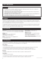
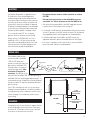
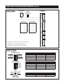
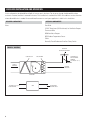
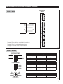
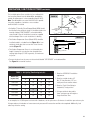
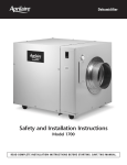
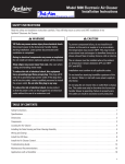
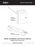
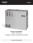
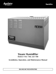
Dehumidifier
Filter
Access
Humidity
Control
Inlet
Filter
Access
Service
Access
Port
Outlet
Drain
Wiring
Access
Wire
Routing
Port
On/Off
Switch
Safety and Installation Instructions
Model 1700
INSTALLER – PLEASE NOTE!
1. Installation must conform to all applicable codes.
2. A dedicated 15 Amp circuit is required for proper
operation of the dehumidifier. If a dedicated circuit
is not available, do not install unit.
3. For protection of the compressor, unit must be
transported and installed in an upright position.
If the unit was shipped or stored on its side, a 24 hour
settling period is required before running the unit.
TABLE OF CONTENTS
Safety Instructions . . . . . . . . . . . . . . .2
Overview . . . . . . . . . . . . . . . . . . . . . . .2
Specifications . . . . . . . . . . . . . . . . . . .2
Location Notes . . . . . . . . . . . . . . . . . .2
Ducting . . . . . . . . . . . . . . . . . . . . . . . .3
Drain Line . . . . . . . . . . . . . . . . . . . . . .3
Hanging . . . . . . . . . . . . . . . . . . . . . . .3
Installations
Whole House . . . . . . . . . . . . . . . . . . .4
Localized . . . . . . . . . . . . . . . . . . . . . . .6
Whole House / Localized
Convertible . . . . . . . . . . . . . . . . . . . . .8
Ventilation and Fan Cycling . . . . . . .10
Float Switch . . . . . . . . . . . . . . . . . . .12
Dip Switch Definitions . . . . . . . . . . .12
System Checkout . . . . . . . . . . . . . . .13
Troubleshooting . . . . . . . . . . . . . . . .14
Sequences
of Operations . . . . . . . . . . .Back Cover
SAFETY INSTRUCTIONS
WARNING
• This product must be installed by a qualified heating and air conditioning contractor. Failure to do so could result in
serious injury from electrical shock or damage to product.
• 120 volts may cause serious injury from electric shock. Disconnect electrical power before starting installation.
Leave power disconnected until installation is completed.
• Sharp edges may cause serious injury from cuts. Use care when cutting plenum openings and handling ductwork.
• Unit weight and dropping may cause personal injury or equipment damage. Handle with care.
OVERVIEW
The purpose of the Aprilaire Dehumidifier is to keep the humidity in the house at acceptable limits to reduce the unwanted
effects of high humidity. The dehumidifier will measure the dewpoint of the house to decide if it needs to run. The dryness set
point can be adjusted with the control knob on the inlet side of the unit.
An integrated air cycling feature can be used to turn on the HVAC fan to cycle the air through the house to balance the indoor
conditions. This feature is set up during installation based on house size and homeowner preference. An optional ventilation
damper can also be installed to bring in outside air during air cycling.
SPECIFICATIONS
Dimensions: 20 3 ⁄ 4”W x 24”L x 20 7⁄ 8”H (mounting feet fully engaged)
20 3 ⁄ 4”W x 24”L x 22 3⁄ 8”H (mounting feet fully extended)
Design Airflow: 275 CFM @ 0.6 in. w.c.
Weight: 93 lbs
Cabinet Insulation: 1” foil faced EPS insulation
Capacity: 90 pints per day @ 60%RH, 80°F
(ANSI/AHAM DH-1-2003 conditions)
Inlet Air Operating Conditions: 40°F to 105°F
Filter: MERV 8 Filter
Ambient Air Operating Conditions: 40°F to 150°F
Power: 115 VAC, 8 Amps. Unit is equipped with an
8 ft. grounded power cord.
LOCATION NOTES
The dehumidifier can be installed in a wide variety of locations (including unconditioned spaces), provided the ambient conditions
are between 40°F and 150°F. Note the following requirements for each application:
Attic / Garage
• All duct work must be insulated.
• Unit should be placed in a drain pan with overflow protection to prevent water damage in the event of a drain failure.
• The condensate line should be insulated to prevent condensation on the outside of the condensate line.
• Precautions should be taken to assure that the unit does not operate in conditions below 40°F or above 150°F.
Basement
• Precautions should be taken to assure that the unit does not operate in conditions below 40°F.
Crawl Space
• All duct work must be insulated.
• The condensate line should be insulated to prevent condensation on the outside of the condensate line.
• Precautions should be taken to assure that the unit does not operate in conditions below 40°F.
2
© Research Products Corporation 2005
DUCTING
The Aprilaire Dehumidifier is supplied with two
8” round collars. These are packaged with a
condensate trap inside the unit behind the filter
access panel. When installing the collar make sure
the foam seal uniformly contacts the cabinet and
secure with 4 screws (not included). UL approved
8” diameter, insulated flexible duct is recommended
for all connections. Rigid metal duct may be used.
The duct should be capable of handling at least
2” w.c. of positive and 0.75” w.c. of negative
pressure. All joints and seams must be sealed.
Design air flow is 275 CFM @ 0.6” w.c. This is
equivalent to 70 ft. of 8” duct on the inlet and
outlet side of the dehumidifier. Elbows, turns and
the static pressure of the HVAC equipment will
affect the airflow through the dehumidifier.
• For optimal moisture removal, airflow should be at or above
275 CFM.
• The total static pressure across the dehumidifier must not
exceed 0.8” w.c. Check all pressures with the HVAC fan on.
• The outlet from the dehumidifier to the HVAC supply duct must be
located at least 6” downstream of the cooling coil.
• If connected to HVAC ductwork, the dehumidifier inlet must be located
at least 6” upstream of the HVAC system air cleaner. This will prevent
any trapped particulates from being drawn into the dehumidifier.
• If UV Germicidal lamps are installed in the HVAC system, use
appropriate methods to protect the flexible duct from the UV light.
• If air noise is a problem, install at least 5 feet of acoustical flexible
duct on the outlet and inlet of the dehumidifier.
DRAIN LINE
The included condensate trap
must be installed to the Model
1700. Use PVC primer and
Drain Outlet
cement to connect the trap to the
drain outlet on the Model 1700.
The drain outlet is located near
the On/Off toggle switch. Note
High Side
orientation of trap prior to
cementing. The high side of the 90-961
trap mates with the Model 1700. The adjustable legs on
the Model 1700 must be disengaged approximately 1” to
accommodate the trap. Complete the assembly by piping
the trap to a drain. The trap must be primed with water
prior to start-up.
FIGURE 1
1/2”
Drain Trap
2 1/2”
Low Side
FIGURE 2
If the 1700 is installed in an attic or in an area where
flooding is a potential problem, it should be installed in a
secondary drain pan with a condensate overflow safety
switch. See page 12 for condensate overflow safety
switch wiring.
3“ MIN
CLEARANCE FOR
ACCESS PANEL
TOP VIEW
20” MINUMUM
CLEARANCE FOR FILTER
(EITHER SIDE)
HANGING
If hanging the unit, use two unistruts to support the base
on the outside edges of the feet locations. There must
be at least 20” of clearance in front of one of the filter
access doors to allow removal of the filter.
FILTER
6" MIN CLEARANCE FOR FILTER
90-970
3
WHOLE HOUSE INSTALLATION AND OPERATION
In this configuration the dehumidifier will pull air from the return duct. The air passes through the dehumidifier, where moisture is
removed, and then returned to the HVAC system downstream of the cooling coil in the supply plenum. This installation is used
when the HVAC unit conditions the area where dehumidification is needed. Connection to the HVAC unit for the primary living
space or basement HVAC unit is ideal for this installation.
REQUIRED COMPONENTS
OPTIONAL COMPONENTS
1 – 6508 Normally Closed Power Open Damper
6506 Ventilation Damper
Duct Work
24 VAC Transformer (10 VA minimum) for Ventilation Damper
24 VAC Transformer (10 VA minimum)
8052 Outdoor Temperature Sensor
Thermostat Wire
Normally Closed Condensate Overflow Safety Switch
FIGURE 3 – DUCTING
COOLING COIL
AIR CLEANER
6“ MIN
6“ MIN
SUPPLY
AIRFLOW
RETURN
AIRFLOW
HVAC UNIT
1700
OPTIONAL N.C.
VENT CONTROL
DAMPER
(SEE PAGES 10-11)
OPTIONAL
OUTDOOR
AIR INTAKE
3‘ MIN
N.C. BACKFLOW DAMPER
90-945
4
WHOLE HOUSE INSTALLATION AND OPERATION (CONTINUED)
N.C. BACKFLOW
DAMPER
FIGURE 4 – WIRING
DEHUMIDIFIER
CONTROL
24 VAC
(10 VA min)
TRANSFORMER
VENT
DEH
DAMPERS
HVAC EQUIPMENT
R
C
G
G
W
W
Y
Y
Y
R
C
Rf Cf Gs Gh W
HVAC EQUIP
THERMOSTAT
FLOAT
SWITCH
ODT
SENSOR
A
B +
REMOTE
See page 10 for ventilation control wiring instructions.
See page 10 for fan cycling wiring instructions.
See page 12 for float switch wiring instructions.
90-962
FIGURE 5 – SETTINGS
SYSTEM SETUP
1
ON
2
3
4
OFF
MODEL 70
HVAC FAN
WHL HOUSE
VENT-AUTO
ON
MODEL 70
HVAC FAN
CONVERTIBLE
VENT-TIMED
CYCLE PERIOD
1
ON
2
3
4
30 MIN.
1 HOUR
2 HOUR
3 HOUR
Standard
Fan Cycling
Ventilation
OFF
See pages 10-11
OFF
OFF
OFF
See pages 10-11
OFF
ON
OFF
See pages 10-11
OFF
OFF
Standard
Fan Cycling
Ventilation
OFF
ON
OFF
OFF
See pages 10-11
See pages 10-11
See pages 10-11
See pages 10-11
See pages 10-11
See pages 10-11
See pages 10-11
See pages 10-11
30
MIN.
0
MIN
60
MIN.
Standard
Fan Cycling
Ventilation
OFF
TEST
OFF
See pages 10-11
See pages 10-11
CYCLE TIME
90-963
5
LOCALIZED INSTALLATION AND OPERATION
In this configuration the dehumidifier will pull air from an area in the home. The air passes through the dehumidifier, where
moisture is removed, and then is returned to the area. This installation is used when the HVAC unit conditions an area other than
where dehumidification is needed. An unconditioned basement or crawl space application is ideal for this installation.
REQUIRED COMPONENTS
OPTIONAL COMPONENTS
None
Duct Work
24 VAC Transformer (10 VA minimum) for Ventilation Damper
Thermostat Wire
6506 Ventilation Damper
8052 Outdoor Temperature Sensor
Grilles
Normally Closed Condensate Overflow Safety Switch
FIGURE 6 – DUCTING
OPTIONAL
OUTDOOR AIR INTAKE
COOLING COIL
OPTIONAL N.C.
VENT CONTROL
DAMPER
(SEE PAGES 10-11)
AIR CLEANER
SUPPLY
AIRFLOW
RETURN
AIRFLOW
HVAC UNIT
TO GRILLE OR
TO OPEN SPACE
1700
FROM GRILLE
OR OPEN SPACE
90-946
6
LOCALIZED INSTALLATION AND OPERATION (CONTINUED)
DEHUMIDIFIER
CONTROL
FIGURE 7 – WIRING
VENT
DEH
DAMPERS
HVAC EQUIPMENT
R
C
G
G
W
W
Y
Y
Y
R
C
Rf Cf Gs Gh W
HVAC EQUIP
THERMOSTAT
FLOAT
SWITCH
ODT
SENSOR
A
B +
REMOTE
See page 10 for ventilation control wiring instructions.
See page 10 for fan cycling wiring instructions.
See page 12 for float switch wiring instructions.
90-964
FIGURE 8 – SETTINGS
SYSTEM SETUP
1
ON
2
3
4
OFF
MODEL 70
HVAC FAN
WHL HOUSE
VENT-AUTO
ON
MODEL 70
HVAC FAN
CONVERTIBLE
VENT-TIMED
CYCLE PERIOD
1
ON
2
3
4
30 MIN.
1 HOUR
2 HOUR
3 HOUR
Standard
Fan Cycling
Ventilation
OFF
See pages 10-11
ON
OFF
OFF
See pages 10-11
ON
ON
OFF
See pages 10-11
ON
OFF
Standard
Fan Cycling
Ventilation
OFF
ON
OFF
OFF
See pages 10-11
See pages 10-11
See pages 10-11
See pages 10-11
See pages 10-11
See pages 10-11
See pages 10-11
See pages 10-11
30
MIN.
0
MIN
60
MIN.
Standard
Fan Cycling
Ventilation
OFF
TEST
OFF
See pages 10-11
See pages 10-11
CYCLE TIME
90-965
7
WHOLE HOUSE / LOCALIZED CONVERTIBLE INSTALLATION AND OPERATION
In this configuration the dehumidifier will automatically switch between whole-house dehumidification when the HVAC
equipment is on, and localized dehumidification when the equipment is off. This installation is used to dehumidify a whole house
and a separate unconditioned space like an unfinished basement, or an area where circulation from that location throughout the
entire house is undesirable.
REQUIRED COMPONENTS
OPTIONAL COMPONENTS
2 – 6508 Normally Closed Power Open Damper
6506 Ventilation Damper
2 – 6608 Normally Open Power Closed Damper
24 VAC Transformer (10 VA minimum) for Ventilation Damper
Duct Work
8052 Outdoor Temperature Sensor
24 VAC Transformer (40 VA minimum)
Normally Closed Condensate Overflow Safety Switch
Thermostat Wire
FIGURE 9 – DUCTING
OPTIONAL
OUTDOOR AIR INTAKE
COOLING COIL
AIR CLEANER
OPTIONAL
N.C. DAMPER
6“ MIN
6“ MIN
3‘ MIN
SUPPLY
AIRFLOW
RETURN
AIRFLOW
HVAC UNIT
N.C. DAMPER
N.C. DAMPER
SUPPLY TO
UNCONDITIONED
SPACE
N.O. DAMPER
RETURN FROM
UNCONDITIONED
SPACE
1700
N.O. DAMPER
90-947
8
WHOLE HOUSE / LOCALIZED CONVERTIBLE INSTALLATION AND OPERATION (CONTINUED)
FIGURE 10 – WIRING
24 VAC
(40 VA min)
TRANSFORMER
DEHUMIDIFIER SYSTEM DAMPERS
DEHUMIDIFIER
CONTROL
VENT
DEH
DAMPERS
THERMOSTAT
HVAC EQUIPMENT
R
C
G
WIRE NUT
G
W
Y
Y
Y
W
Rf Cf Gs Gh W
HVAC EQUIP.
R
C
FLOAT
SWITCH
ODT
SENSOR
A
B +
REMOTE
See page 10 for ventilation control wiring instructions.
See page 10 for fan cycling wiring instructions.
See page 12 for float switch wiring instructions.
90-966
FIGURE 11 – SETTINGS
SYSTEM SETUP
1
ON
2
3
4
OFF
MODEL 70
HVAC FAN
WHL HOUSE
VENT-AUTO
ON
MODEL 70
HVAC FAN
CONVERTIBLE
VENT-TIMED
CYCLE PERIOD
1
ON
2
3
4
30 MIN.
1 HOUR
2 HOUR
3 HOUR
Standard
Fan Cycling
Ventilation
OFF
OFF
ON
OFF
OFF
OFF
ON
ON
OFF
OFF
ON
OFF
Standard
Fan Cycling
Ventilation
OFF
ON
OFF
OFF
See pages 10-11
See pages 10-11
See pages 10-11
See pages 10-11
See pages 10-11
See pages 10-11
See pages 10-11
See pages 10-11
30
MIN.
0
MIN
60
MIN.
Standard
Fan Cycling
Ventilation
OFF
TEST
OFF
See pages 10-11
See pages 10-11
CYCLE TIME
90-965
9
VENTILATION / FAN CYCLING SETTINGS
OPTIONAL
VENTILATION
DAMPER
FIGURE 12
24 VAC
(10 VA min)
TRANSFORMER
DEHUMIDIFIER
CONTROL
VENT
DEH
DAMPERS
THERMOSTAT
HVAC EQUIPMENT
R
R
C
C
G
WIRE NUT
G
W
Y
Y
Y
W
Rf Cf Gs Gh W
HVAC EQUIP.
The Aprilaire Dehumidifier has the option
to monitor HVAC heating, cooling and fan
calls to assure the HVAC fan has
operated a predetermined amount of
time each 1/2, 1, 2 or 3 hours. The
dehumidifier can also open a normally
closed damper in an outdoor air intake to
ventilate during this predetermined
amount of time. This feature will
function even if the dehumidifier is
turned off at the dehumidifier or Model
70 Living Space Control. The only way to
disable this feature is by turning the
Cycle Time setting to OFF or turning
power off at the On/Off switch.
FLOAT
SWITCH
ODT
SENSOR
OPTIONAL OUTDOOR
TEMPERATURE SENSOR
(Model 8052)
A
B +
REMOTE
90-968
First, set the 1/2, 1, 2 or 3 hour period by setting the CYCLE PERIOD dip switches to determine
how often the dehumidifier should look to ventilate or cycle the HVAC fan.
ON
4
90-783C
(shown set to
30 minutes)
FIGURE 14
30
MIN.
0
MIN
60
MIN.
OFF
TEST
CYCLE TIME
90-783C
FIGURE 15
SYSTEM SETUP
ON
2
3
4
OFF
MODEL 70
HVAC FAN
WHL HOUSE
VENT-AUTO
1
10
3
You can also check the wiring of the dehumidifier to the HVAC equipment. If you rotate the
CYCLE TIME dial to TEST, the HVAC fan should come on and the Ventilation Damper
(if equipped) should open. DO NOT leave the CYCLE TIME in TEST.
30 MIN.
1 HOUR
2 HOUR
3 HOUR
2
Finally, if using the Ventilation Damper, determine if the ventilation should be restricted based
on outdoor temperature. Set the VENT-AUTO / VENT-TIMED dip switch to VENT-AUTO
(see Figure 15) to prevent opening the ventilation damper if the outdoor air is above 100°F,
below 0°F or except with a heat call between 20°F and 0°F. In the VENT-TIMED setting the
ventilation damper is activated regardless of outdoor conditions. Note: The Outdoor
Temperature Sensor (Model 8052) must be installed for this to work.
CYCLE PERIOD
1
Next, use the CYCLE TIME dial to determine how long during every cycle period the HVAC fan
should operate. Adjust the dial from OFF to between 1 to 60 minutes. This will give you HVAC fan
operation from 1 to 60 minutes every 1/2, 1, 2 or 3 hours. A call for heat, cooling or fan from the
HVAC equipment will often satisfy the run time requirement. If not, the dehumidifier will turn on
the HVAC fan to assure that the cycle time is met. For example: If the home requires
ventilation of 20 minutes every two hours set the CYCLE PERIOD Dip Switch for 2 hours
to ON and rotate the CYCLE TIME to 20 minutes. If the HVAC equipment only has to run
for 10 minutes, the dehumidifier will turn on the HVAC fan for 10 minutes at the end of
the 2 hours to assure the ventilation / fan cycling time.
(shown set
to 1 hour)
FIGURE 13
ON
MODEL 70
HVAC FAN
CONVERTIBLE
VENT-TIMED
90-969
VENTILATION / FAN CYCLING SETTINGS (CONTINUED)
This installed option allows outside air to be combined with
the fan cycling feature from the dehumidifier, provided the
outside air temperature is in the acceptable range (0-100°F).
Note: The dehumidifier can control the HVAC fan to provide
fan cycling, regardless of whether or not an outdoor
ventilation duct is installed.
FIGURE 16
NORTH, EAST
OR WEST SIDE
OF HOME
OUTDOOR
TEMPERATURE
SENSOR
SENSOR
• An Aprilaire® Normally-Closed Damper (Model 6506) should
be installed in the outside air intake. It should be wired to the
terminals labeled “VENT DAMPER” on the dehumidifier
control board. Follow all installation instructions supplied
with the damper. Refer to each installation for ducting.
SENSOR
BRACKET
OUTDOOR
TEMPERATURE SENSOR
LEADS
ABOVE EXPECTED
SNOW LINE
B2202617-D
FIGURE 17
• The Outdoor Temperature Sensor (Model 4278) should be
installed outside in a shaded location (Figure 16) or in an
outside air intake duct, but no more than 3 feet from the
outside (Figure 17).
CENTER LINE
36" MAX.
• The Outdoor Temperature Sensor is not affected by wire
length. However, do not route the wire alongside wires
carrying high voltage (115 VAC or greater), as interference
may occur.
OUTSIDE WALL
B2202617-E
• Connect the wires from the sensor to the terminals labeled “ODT SENSOR” on the dehumidifier.
See Figure 12 for terminal locations.
VENTILATION GUIDELINES
TABLE 1 – Air Cycling Time Setting (min./hr.)
1. Based on ASHRAE 62.2 ventilation
requirement.
Bedrooms
House Size
(square feet)
2
3
4
5
1000-1500
20
25
30
35
1501-2000
25
30
30
35
2001-2500
25
30
35
40
2501-3000
30
35
40
40
3001-3500
30
35
40
45
2. Based on outside air duct of 6”
dia., 20’ long flex duct, 0.15” w.c.
static pressure at outdoor air duct.
3. Based on ‘Cycle Period’ being in
the default (1 hour) position.
4. A longer outside air duct and/or
lower static pressure will require a
longer Ventilation Time.
As an example, for a 2,500 square foot home with 3 bedrooms, set the cycle time to 30 minutes of ventilation per one-hour cycle.
A longer outdoor air intake duct or lower return static pressure will increase the ventilation time required. Additionally, local
codes may affect the setting.
11
FLOAT SWITCH
FIGURE 18
ODT
SENSOR
LOW VOLTAGE NORMALLY
CLOSED FLOAT SWITCH
FLOAT
SWITCH
If the Model 1700 is installed in an attic, the unit should be
placed in a drain pan with a normally closed condensate overflow
safety switch (also known as a float switch). The float switch
should be wired to the float switch terminals on the dehumidifier
control board. See Figure 18. Remove the jumper at the float
switch terminals. The compressor is disabled when the float
switch is open. The Model 1700 will continue to ventilate when
the float switch is open.
90-968A
DIP SWITCH DEFINITIONS
MODEL 70 – OFF/ON (SYSTEM SETUP SWITCH #1):
Determines use of internal RH and temperature sensor or use
of the RH and temperature sensor on the Living Space Control
(Model 70).
MODEL 70-OFF. Uses inlet RH and temperature sensor.
MODEL 70-ON. Uses Living Space Control (Model 70)
RH and Temperature Sensor.
Default is MODEL 70-OFF.
HVAC FAN – OFF/ON (SYSTEM SETUP SWITCH #2):
Determines if the HVAC fan activates during a call for
dehumidification.
HVAC FAN-OFF position. The dehumidifier will not activate
the HVAC fan during a call for dehumidification; it will
however activate the HVAC fan for air cycling and ventilation.
HVAC FAN-ON position. The dehumidifier will activate the
HVAC fan during a call for dehumidification as well as for air
cycling and ventilation.
Default is HVAC FAN-OFF.
WHL HOUSE / CONVERTIBLE (SYSTEM SETUP SWITCH #3):
Determines when the dampers are powered open or closed.
CONVERTIBLE position. The damper (DEH) terminals are
actuated when the HVAC equipment is making a call for heat,
cool or fan and the dehumidifier is making an internal blower
call for air sampling or dehumidification.
WHL HOUSE position. The damper (DEH) terminals are
actuated any time the dehumidifier is making an internal
blower call for air sampling or dehumidification.
The default position is WHL HOUSE.
VENT-AUTO / VENT-TIMED (SYSTEM SETUP SWITCH #4):
Determines if ventilation is restricted based on outdoor
temperature
VENT-AUTO position. The dehumidifier will measure the
outdoor temperature (through sensor, part # 8052) to
determine if the ventilation damper will open. If the outside
temperature is above 100°F or below 0°F the dehumidifier
will not actuate the ventilation damper terminals (VENT
DAMPER). If the outside temperature is between 0°F - 20°F,
the dehumidifier will only actuate the ventilation damper
terminals (VENT DAMPER) when the HVAC system is making
a call for heat. The dehumidifier will energize the HVAC fan
whether or not the ventilation damper opens.
VENT-TIMED position. The dehumidifier will actuate the
ventilation damper terminals (VENT DAMPER) regardless of
the outdoor temperature.
The default position is VENT-AUTO.
12
SYSTEM CHECKOUT
1. Check the wiring to the HVAC equipment.
2. Rotate the main control knob clockwise to the “TEST” position.
3. If all is set up properly, the dehumidifier blower will turn on. The compressor will turn on after the dehumidifier blower has run
for 30 seconds. After 1 minute the dehumidifier blower and compressor will shut off (“TEST” mode only).
4. If the dehumidifier blower does not activate in TEST mode, refer to the Troubleshooting Guide.
5. For ventilation (optional) test, be sure that 24 VAC is applied in series with the Aprilaire® Normally-Closed Damper
(Model 6506) and connected to the “VENT DAMPER” terminals on the dehumidifier control.
6. Rotate the “CYCLE TIME” potentiometer clockwise to the “TEST” position.
7. If all is set up properly, the HVAC blower will turn on and the ventilation damper will open. Both should be audible to the
installer. The HVAC blower will remain on and the ventilation damper will remain open for 1 minute or until the dial is turned
from the “TEST” position, whichever happens first.
8. If the optional ventilation damper or HVAC blower does not activate in TEST mode, refer to the Troubleshooting Guide.
13
TROUBLESHOOTING GUIDE
SYMPTOM
TROUBLESHOOTING PROCEDURE / POSSIBLE REASON
Dehumidifier is producing
hot air.
• Reheat of outgoing air will cause a temperature increase across the dehumidifier.
Dehumidifier Blower is running,
but no airflow.
• Normally Open Damper was used instead of Normally Closed Damper in backflow.
Dehumidifier not adequately
dehumidifying.
• Unit will need time to “dry” materials in home before effectively changing RH.
• Unit will possibly run continuously initially. After unit has “dried” home,
dehumidifier will cycle, reducing load.
• Total HVAC system static is higher than 0.8” w.c.
• Too little airflow through dehumidifier.
• Total HVAC system static is higher than 0.8” w.c.
• Compressor is not turning on.
• System undercharged.
Dehumidifier is not
draining properly.
• Check condensate trap to be sure it is clear.
HVAC fan does not turn
on when cycle time dial is
in “TEST” mode.
• Make sure there is power to the HVAC equipment.
• Check drain line for continuous slope.
• Check the wiring diagram for the R, C, W, Y, GH, and GS at the HVAC equipment,
thermostat, and the dehumidifier.
• Make sure the sensor is connected to the Outdoor Temperature Sensor terminals
or the System Setup block is set to “TIMED” mode.
• Check the voltage across the R and C terminals at the dehumidifier. Voltage
should be 18 VAC minimum - 30 VAC maximum.
• In “TEST” Mode, the HVAC fan will activate for 1 minute, DO NOT LEAVE IN TEST
MODE AS DEHUMIDIFIER WILL NOT OPERATE.
The dehumidifier damper does
not open in “TEST” Mode.
• Follow all of the system checkout procedures.
Fan cycling operates
continuously after the dial
is taken off “TEST” mode.
• If the HVAC equipment is making a Heat or Cool call, or the fan is in Continuous
Operation, fan cycling will remain on until the requirement set by the cycle
period dip switch and knob is met.
• Check the wiring diagram for the damper and 24 VAC transformers.
• If the interval is set at 1 HOUR and the cycle time is set at 60 minutes, fan
cycling will be on continuously. Change the setting to a lower amount if this is
not desired.
14
TROUBLESHOOTING GUIDE (CONTINUED)
SYMPTOM
The ventilation damper
does not open when the
HVAC fan is active.
TROUBLESHOOTING PROCEDURE / POSSIBLE REASON
• The damper will not open if the cycle time within the current period has already
been met. For instance if the cycle time is set to 5 minutes and the control has
already ventilated for 5 minutes in that interval, the damper will remain closed.
• If using the Outdoor Temperature Sensor, check
that it is installed in the Outdoor Air Intake a
maximum of 3 feet from the outside, or on the
North, East or West side of the house.
(Not in direct sunlight.)
• If the outdoor temperature is below 0°F or above
100°F, the damper will remain closed.
• Verify that the Outdoor Temperature Sensor
is reporting an accurate resistance. Remove the
Outdoor Temperature Sensor leads from ODT
Sensor terminals and check the resistance.
Compare the reading with the resistance shown
in Table 2.
TABLE 2
Outdoor
Temperature
Resistance
-30˚F
229,500 OHMS
-20˚F
162,500 OHMS
-10˚F
116,500 OHMS
0˚F
84,500 OHMS
10˚F
62,000 OHMS
20˚F
46,000 OHMS
30˚F
34,500 OHMS
40˚F
26,000 OHMS
50˚F
20,000 OHMS
60˚F
15,500 OHMS
70˚F
12,000 OHMS
80˚F
9,500 OHMS
90˚F
7,500 OHMS
100˚F
6,000 OHMS
The fan turns on unexpectedly.
• The control will turn on the fan as needed to meet the air cycling requirements
determined by the cycle time and cycle period settings.
The dehumidifier does not run.
• Follow all of the system checkout procedures.
• Check that the power switch on the dehumidifier is on.
• Check that the circuit breaker is not tripped. The dehumidifier requires a
minimum of 8 amps. The dehumidifier should be placed on its own dedicated
15 amp circuit.
The compressor never runs.
• If a float switch is not installed, confirm that the jumper is installed at the
float switch terminals on the control board.
• If a float switch is installed, confirm that the float switch is not open.
15
DEHUMIDIFIER SEQUENCE OF OPERATION
IF THE DEHUMIDIFIER IS NOT WIRED TO THE HVAC EQUIPMENT, THE DEHUMIDIFIER WILL SAMPLE AT THE END OF THE
CYCLE PERIOD.
With 3 minutes left in the Cycle Period, the dehumidifier will turn on the dehumidifier blower for 2 minutes. During this time the
temperature and relative humidity are measured and the dewpoint is calculated. If the dewpoint is higher than the setting at the
Control Knob then the dehumidifier compressor will turn on and the dehumidifier will run until it reaches set point.
After reaching the set point, the dehumidifier will not sample again until the end of the next Sample Period.
For example, if the Sample Period is set for 1 hour, the dehumidifier will sample at the end of the hour. Once the dehumidifier
reaches set point and shuts off, the dehumidifier will not sample again until the end of the next hour.
IF THE DEHUMIDIFIER IS WIRED INTO THE HVAC EQUIPMENT, THE DEHUMIDIFIER WILL SAMPLE THE FIRST TIME THE HVAC
EQUIPMENT RUNS IN THE CYCLE PERIOD OR AT THE END OF THE CYCLE PERIOD IF THE HVAC EQUIPMENT DOES NOT RUN.
For example, if the Cycle Period is set to 1 hour and the air conditioner starts 15 minutes into that hour, the dehumidifier will
sample when the air conditioner starts. Once the dehumidifier begins dehumidifying, it will run until set point is reached. If the
dehumidifier samples and determines that dehumidification is not needed, it will not sample again until the next Cycle Period.
DAMPER SEQUENCE OF OPERATION
In the Whole House Convertible to Localized installation 4 motorized dampers are used to control the air flow through the
dehumidifier. The dampers are energized when the HVAC equipment is running. This means that when the HVAC equipment
is running, the dampers are in the Whole-House position. When the HVAC equipment is not running, the dampers are in the
local position.
VENTILATION OR FAN CYCLING SEQUENCE OF OPERATION
If the dehumidifier is providing outdoor air ventilation or fan cycling, it is monitoring the HVAC equipment to provide the amount
of HVAC fan run time that has been set by the Cycle Time during the Cycle Period.
If an outdoor air damper has not been installed then the dehumidifier is providing fan cycling. The dehumidifier will monitor the
HVAC system and if the system has not run for the specified Cycle Time within the Cycle Period, the dehumidifier will energize
the HVAC fan through the G terminal to provide the desired amount of fan run time.
For example, if the Cycle Time is set for 10 minutes and the Cycle Period is set for 1 hour then the dehumidifier will provide
10 minutes of fan cycling or outdoor air ventilation. If the HVAC system runs for 5 minutes during this hour then the dehumidifier
will energize the fan for an additional 5 minutes.
If an outdoor air damper has been installed, then the Model 1700 is providing outdoor air ventilation. The 1700 will open the
outdoor air damper whenever the HVAC system is running, up to the amount of time specified by the Cycle Time. The
dehumidifier will energize the HVAC fan and open the outdoor air damper to provide the desired ventilation time if the HVAC
system has not run for the specified Cycle Time.
If an Outdoor Temperature Sensor has been installed, then the dehumidifier will use the outdoor temperature to determine if the
outdoor air damper is to be opened. If the outdoor temperature is above 100°F the damper will not open. If the temperature is
between 20°F and 0°F the damper will only open with a heat call. If the outdoor temperature is below 0°F, the damper will not
open. If the Outdoor Temperature Sensor is not installed then the temperature is not considered in opening the damper.
10006238 5.05
B2203431C
P.O. BOX 1467 • MADISON, WI 53701-1467 • PHONE: 800/334-6011 • FAX: 608/257-4357 • www.aprilairecontractor.com