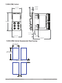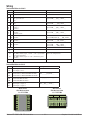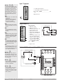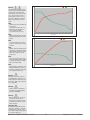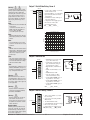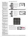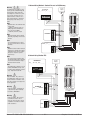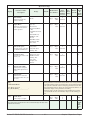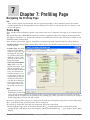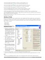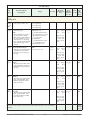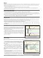
1
EZ-ZONE PM ® User’s Guide PID Controller Models TOTAL CUSTOMER SATISFACTION 3 Year Warranty ISO 9001 Registered Company Winona, Minnesota USA 1241 Bundy Boulevard., Winona, Minnesota USA 55987 Phone: +1 (507) 454-5300, Fax: +1 (507) 452-4507 http://www.watlow.com 0600-0058-0000 Rev. N January 2015 Made in the U.S.A. Safety Information Unit is a Listed device per Underwriters Laboratories®. It has been evaluated to United States and Canadian requirements for Hazardous Locations Class 1 Division II Groups A, B, C and D. ANSI/ISA 12.12.01-2007. File E184390 QUZW, QUZW7. See: www.ul.com We use note, caution and warning symbols throughout this book to draw your attention to important operational and safety information. A “NOTE” marks a short message to alert you to an important detail. A “CAUTION” safety alert appears with information that is important for protecting your equipment and performance. Be especially careful to read and follow all cautions that apply to your application. Unit is compliant with European Union directives. See Declaration of Conformity for further details on Directives and Standards used for Compliance. A “WARNING” safety alert appears with information that is important for protecting you, others and equipment from damage. Pay very close attention to all warnings that apply to your application. The electrical hazard symbol, Ó (a lightning bolt in a triangle) precedes an electric shock hazard CAUTION or WARNING safety statement. Symbol Unit has been reviewed and approved by Factory Mutual as a Temperature Limit Device per FM Class 3545 standard. See: www.fmglobal.com Unit has been reviewed and approved by CSA International for use as Temperature Indicating-Regulating Equipment per CSA C22.2 No. 24. See: www. csa-international.org Explanation Unit has been reviewed and approved by ODVA for compliance with DeviceNet communications protocol. See: www.odva.org CAUTION – Warning or Hazard that needs further explanation than label on unit can provide. Consult User's Guide for further information. ESD Sensitive product, use proper grounding and handling techniques when installing or servicing product. Unit protected by double/reinforced insulation for shock hazard prevention. Do not throw in trash, use proper recycling techniques or consult manufacturer for proper disposal. Enclosure made of Polycarbonate material. Use proper recycling techniques or consult manufacturer for proper disposal. Unit can be powered with either alternating current (ac) voltage or direct current (dc) voltage. Unit is a Listed device per Underwriters Laboratories®. It has been evaluated to United States and Canadian requirements for Process Control Equipment. UL 61010 and CSA C22.2 No. 61010. File E185611 QUYX, QUYX7. See: www.ul.com Unit has been reviewed and approved by ODVA for compliance with Ethernet/IP communications protocol. See: www.odva. org Warranty The EZ-ZONE® PM is manufactured by ISO 9001-registered processes and is backed by a threeyear warranty to the first purchaser for use, providing that the units have not been misapplied. Since Watlow has no control over their use, and sometimes misuse, we cannot guarantee against failure. Watlow’s obligations hereunder, at Watlow’s option, are limited to replacement, repair or refund of purchase price, and parts which upon examination prove to be defective within the warranty period specified. This warranty does not apply to damage resulting from transportation, alteration, misuse or abuse. The purchaser must use Watlow parts to maintain all listed ratings. Technical Assistance If you encounter a problem with your Watlow controller, review your configuration information to verify that your selections are consistent with your application: inputs, outputs, alarms, limits, etc. If the problem persists, you can get technical assistance from your local Watlow representative (see back cover), by e-mailing your questions to wintechsupport@watlow. com or by dialing +1 (507) 494-5656 between 7 a.m. and 5 p.m., Central Standard Time (CST). Ask for for an Applications Engineer. Please have the following information available when calling: • Complete model number • All configuration information • User's Guide • Factory Page Return Material Authorization (RMA) 1. Call Watlow Customer Service, (507) 454-5300, for a Return Material Authorization (RMA) number before returning any item for repair. If you do not know why the product failed, contact an Application Engineer or Product Manager. All RMA’s require: • Ship-to address • Bill-to address • Contact name • Phone number • Method of return shipment • Your P.O. number • Detailed description of the problem • Any special instructions • Name and phone number of person returning the product. 2. Prior approval and an RMA number from the Customer Service Department is required when returning any product for credit, repair or evaluation. Make sure the RMA number is on the outside of the carton and on all paperwork returned. Ship on a Freight Prepaid basis. 3. After we receive your return, we will examine it and try to verify the reason for returning it. 4. In cases of manufacturing defect, we will enter a repair order, replacement order or issue credit for material returned. In cases of customer misuse, we will provide repair costs and request a purchase order to proceed with the repair work. 5. To return products that are not defective, goods must be in new condition, in the original boxes and they must be returned within 120 days of receipt. A 20 percent restocking charge is applied for all returned stock controls and accessories. 6. If the unit is not repairable, you will receive a letter of explanation. and be given the option to have the unit returned to you at your expense or to have us scrap the unit. 7. Watlow reserves the right to charge for no trouble found (NTF) returns. The EZ-ZONE® PM PID Controller User's Guide is copyrighted by Watlow Electric, Inc., © January 2015 with all rights reserved. EZ-ZONE® PM is covered by U.S. Patent No. 6,005,577 and Patents Pending TC Table of Contents Chapter 1: Overview . . . . . . . . . . . . . . . . . . . . . . . . . . . . . . . . . . . . . 3 Standard Features and Benefits . . . . . . . . . . . . . . . . . . . . . . . . . . . . . . . . 3 Getting Started Quickly. . . . . . . . . . . . . . . . . . . . . . . . . . . . . . . . . . . . . 5 Chapter 2: Install and Wire. . . . . . . . . . . . . . . . . . . . . . . . . . . . . . . . . 7 Dimensions. . . . . . . . . . . . . . . . . . . . . . . . . . . . . . . . . . . . . . . . . . . . . . . . 7 Installation . . . . . . . . . . . . . . . . . . . . . . . . . . . . . . . . . . . . . . . . . . . . . . . 12 Wiring. . . . . . . . . . . . . . . . . . . . . . . . . . . . . . . . . . . . . . . . . . . . . . . . . . . 14 Chapter 3: Keys and Displays. . . . . . . . . . . . . . . . . . . . . . . . . . . . . . 26 Chapter 4: Home Page. . . . . . . . . . . . . . . . . . . . . . . . . . . . . . . . . . . 28 Conventions Used in the Menu Pages . . . . . . . . . . . . . . . . . . . . . . . . . . 33 Chapter 5: Operations Page . . . . . . . . . . . . . . . . . . . . . . . . . . . . . . . 35 Analog Input Menu. . . . . . . . . . . . . . . . . . . . . . . . . . . . . . . . . . . . . . . . . 36 Linearization Menu. . . . . . . . . . . . . . . . . . . . . . . . . . . . . . . . . . . . . . . . . 36 Process Value Menu. . . . . . . . . . . . . . . . . . . . . . . . . . . . . . . . . . . . . . . . 37 Digital Input/Output Menu . . . . . . . . . . . . . . . . . . . . . . . . . . . . . . . . . . . 38 Monitor Menu. . . . . . . . . . . . . . . . . . . . . . . . . . . . . . . . . . . . . . . . . . . . . 38 Control Loop Menu. . . . . . . . . . . . . . . . . . . . . . . . . . . . . . . . . . . . . . . . . 39 Alarm Menu . . . . . . . . . . . . . . . . . . . . . . . . . . . . . . . . . . . . . . . . . . . . . . 41 Timer Menu . . . . . . . . . . . . . . . . . . . . . . . . . . . . . . . . . . . . . . . . . . . . . . 42 Profile Status Menu . . . . . . . . . . . . . . . . . . . . . . . . . . . . . . . . . . . . . . . . 44 Chapter 6: Setup Page. . . . . . . . . . . . . . . . . . . . . . . . . . . . . . . . . . . 47 Analog Input Menu. . . . . . . . . . . . . . . . . . . . . . . . . . . . . . . . . . . . . . . . . 49 Linearization Menu. . . . . . . . . . . . . . . . . . . . . . . . . . . . . . . . . . . . . . . . . 51 Process Value Menu. . . . . . . . . . . . . . . . . . . . . . . . . . . . . . . . . . . . . . . . 53 Digital Input/Output Menu . . . . . . . . . . . . . . . . . . . . . . . . . . . . . . . . . . . 54 Control Loop Menu. . . . . . . . . . . . . . . . . . . . . . . . . . . . . . . . . . . . . . . . . 56 Output Menu. . . . . . . . . . . . . . . . . . . . . . . . . . . . . . . . . . . . . . . . . . . . . . 61 Alarm Menu . . . . . . . . . . . . . . . . . . . . . . . . . . . . . . . . . . . . . . . . . . . . . . 64 Timer Menu . . . . . . . . . . . . . . . . . . . . . . . . . . . . . . . . . . . . . . . . . . . . . . 67 Function Key Menu. . . . . . . . . . . . . . . . . . . . . . . . . . . . . . . . . . . . . . . . . 68 Global Menu. . . . . . . . . . . . . . . . . . . . . . . . . . . . . . . . . . . . . . . . . . . . . . 69 Communications Menu. . . . . . . . . . . . . . . . . . . . . . . . . . . . . . . . . . . . . . 71 Real Time Clock Menu. . . . . . . . . . . . . . . . . . . . . . . . . . . . . . . . . . . . . . 73 Watlow EZ-ZONE ® PM PID Controller • 1 • Table of Contents TC Table of Contents (cont.) Chapter 7: Profiling Page. . . . . . . . . . . . . . . . . . . . . . . . . . . . . . . . . 74 Profile Setup. . . . . . . . . . . . . . . . . . . . . . . . . . . . . . . . . . . . . . . . . . . . . . 74 Starting a Profile. . . . . . . . . . . . . . . . . . . . . . . . . . . . . . . . . . . . . . . . . . . 75 Profiling Menu . . . . . . . . . . . . . . . . . . . . . . . . . . . . . . . . . . . . . . . . . . . . 78 Chapter 8: Factory Page. . . . . . . . . . . . . . . . . . . . . . . . . . . . . . . . . . 82 Custom Menu. . . . . . . . . . . . . . . . . . . . . . . . . . . . . . . . . . . . . . . . . . . . . 83 Security Setting Menu . . . . . . . . . . . . . . . . . . . . . . . . . . . . . . . . . . . . . . 83 Security Setting Menu . . . . . . . . . . . . . . . . . . . . . . . . . . . . . . . . . . . . . . 85 Diagnostics Menu. . . . . . . . . . . . . . . . . . . . . . . . . . . . . . . . . . . . . . . . . . 85 Calibration Menu . . . . . . . . . . . . . . . . . . . . . . . . . . . . . . . . . . . . . . . . . . 86 Chapter 9: Features. . . . . . . . . . . . . . . . . . . . . . . . . . . . . . . . . . . . . 87 Changing PM PID Model Number to PM User Mode. . . . . . . . . . . . . . . 88 Saving and Restoring User Settings. . . . . . . . . . . . . . . . . . . . . . . . . . . . 89 Programming the Home Page . . . . . . . . . . . . . . . . . . . . . . . . . . . . . . . . 90 Tuning the PID Parameters. . . . . . . . . . . . . . . . . . . . . . . . . . . . . . . . . . . 90 Inputs. . . . . . . . . . . . . . . . . . . . . . . . . . . . . . . . . . . . . . . . . . . . . . . . . . . 92 Outputs. . . . . . . . . . . . . . . . . . . . . . . . . . . . . . . . . . . . . . . . . . . . . . . . . . 95 Control Methods. . . . . . . . . . . . . . . . . . . . . . . . . . . . . . . . . . . . . . . . . . . 97 Timer Function. . . . . . . . . . . . . . . . . . . . . . . . . . . . . . . . . . . . . . . . . . . 102 Alarms . . . . . . . . . . . . . . . . . . . . . . . . . . . . . . . . . . . . . . . . . . . . . . . . . 105 Open Loop Detection . . . . . . . . . . . . . . . . . . . . . . . . . . . . . . . . . . . . . . 106 Programming the EZ Key/s. . . . . . . . . . . . . . . . . . . . . . . . . . . . . . . . . . 106 Using Lockout and Password Security. . . . . . . . . . . . . . . . . . . . . . . . . 107 Using Lockout Method 1 (Read and Set Lock). . . . . . . . . . . . . . . . . 107 Using Lockout Method 2 (Password Enable). . . . . . . . . . . . . . . . . . 108 Modbus - Using Programmable Memory Blocks. . . . . . . . . . . . . . . . . 109 Software Configuration. . . . . . . . . . . . . . . . . . . . . . . . . . . . . . . . . . . . . 110 Chapter 10: Appendix . . . . . . . . . . . . . . . . . . . . . . . . . . . . . . . . . . 113 Troubleshooting Alarms, Errors and Control Issues. . . . . . . . . . . . . . . 113 Modbus - Programmable Memory Blocks. . . . . . . . . . . . . . . . . . . . . . 117 Specifications. . . . . . . . . . . . . . . . . . . . . . . . . . . . . . . . . . . . . . . . . . . . 119 Ordering Information for PID Controller Models . . . . . . . . . . . . . . . . . 121 Index. . . . . . . . . . . . . . . . . . . . . . . . . . . . . . . . . . . . . . . . . . . . . . . . . . . 122 How to Reach Us. . . . . . . . . . . . . . . . . . . . . . . . . . . . . . . . . . . . . . . . . 128 Watlow EZ-ZONE ® PM PID Controller • 2 • Table of Contents 1 Chapter 1: Overview The EZ-ZONE ® PM takes the pain out of solving your thermal loop requirements. Watlow’s EZ-ZONE PM controllers offer options to reduce system complexity and the cost of control-loop ownership. You can order the EZ-ZONE PM as a PID controller or an over-under limit controller, or you can combine both functions in the PM Integrated Limit Controller. You now have the option to integrate a highamperage power controller output, an over-under limit controller and a high-performance PID controller all in space-saving, panel-mount packages. You can also select from a number of serial communications options to help you manage system performance. It just got a whole lot easier to solve the thermal requirements of your system. Because the EZ-ZONE PM controllers are highly scalable, you only pay for what you need. So if you are looking for a PID controller, an over-under limit controller or an integrated controller, the EZ-ZONE PM is the answer. Standard Features and Benefits Advanced PID Control Algorithm • TRU-TUNE+ ® Adaptive tune provides tighter control for demanding applications. • Auto Tune for fast, efficient start ups High-amperage Power Control Output • Drives 15 amp resistive loads directly • Reduces component count • Saves panel space and simplifies wiring • Reduces the cost of ownership EZ-ZONE configuration communications and software • Saves time and improves the reliability of controller set up Parameter Save & Restore Memory • Reduces service calls and down time Agency approvals: UL Listed, CSA, CE, RoHS, W.E.E.E. FM • Assures prompt product acceptance • Reduces end product documentation costs • Semi F47-0200 P3T Armor Sealing System • NEMA 4X and IP65 offers water and dust resistance, can be cleaned and washed down (indoor use only) • Backed up by UL 50 independent certification to NEMA 4X specification Three-year warranty • Demonstrates Watlow’s reliability and product support Touch-safe Package • IP2X increased safety for installers and operators Removable cage clamp wiring connectors • Reliable wiring, reduced service calls • Simplified installation EZ-Key/s Watlow EZ-ZONE ® PM PID Controller • 3 • Chapter 1 Over view • Programmable EZ-Key enables simple one-touch operation of repetitive user activities Programmable Menu System • Reduces set up time and increases operator efficiency Full-featured Alarms • Improves operator recognition of system faults • Control of auxiliary devices Heat-Cool Operation • Provides application flexibility with accurate temperature and process control Profile Capability • Preprogrammed process control • Ramp and soak programming with four files and 40 total steps A Conceptual View of the PM The flexibility of the PM’s software and hardware allows a large range of configurations. Acquiring a better understanding of the controller’s overall functionality and capabilities while at the same time planning out how the controller can be used will deliver maximum effectiveness in your application. It is useful to think of the controller in three parts: inputs; procedures; and outputs. Information flows from an input to a procedure to an output when the controller is properly configured. A single PM controller can carry out several procedures at the same time, for instance closed-loop control, monitoring for several different alarm situations and operating switched devices, such as lights and motors. Each process needs to be thought out carefully and the controller’s inputs, procedures and outputs set up properly. Inputs The inputs provide the information that any given programmed procedure can act upon. In a simple form, this information may come from an operator pushing a button or as part of a more complex procedure it may represent a remote set point being received from another controller. Each analog input typically uses a thermocouple or RTD to read the temperature of something. It can also read volts, current or resistance, allowing it to use various devices to read humidity, air pressure, operator inputs and others values. The settings in the Analog Input Menu (Setup Page) for each analog input must be configured to match the device connected to that input. Each digital input reads whether a device is active or inactive. A PM with digital input-output hardware includes two sets of terminals each of which can be used as either an input or an output. Each pair of terminals must be configured to function as either an input or output with the Direction parameter in the Digital Input/Output Menu (Setup Page). The Function or EZ Key on the front panel of the PM also operates as a digital input by toggling the function assigned to it in the Digital Input Function parameter in the Function Key Menu (Setup Page). Functions Functions use input signals to calculate a value. A function may be as simple as reading a digital input to set a state to true or false, or reading a temperature to set an alarm state to on or off. Or, it could compare the temperature of a process to the set point and calculate the optimal power for a heater. To set up a function, it’s important to tell it what source, or instance, to use. For example, an alarm may be set to respond to either analog input 1 or 2 (instance 1 or 2, respectively). Keep in mind that a function is a user-programmed internal process that does not execute any action outside of the controller. To have any effect outside of the controller, an output must be configured to respond to a function. Outputs Outputs can perform various functions or actions in response to information provided by a function, such as operating a heater; turning a light on or off; unlocking a door; or turning on a buzzer. Assign an output to a Function in the Output Menu or Digital Input/Output Menu. Then select which instance of that function will drive the selected output. For example, you might assign an output to respond to alarm 4 (instance 4) or to retransmit the value of analog input 2 (instance 2). Watlow EZ-ZONE ® PM PID Controller • 4 • Chapter 1 Over view You can assign more than one output to respond to a single instance of a function. For example, alarm 2 could be used to trigger a light connected to output 1 and a siren connected to digital output 5. Input Events and Output Events Input and output events are internal states that are used exclusively by profiles. The source of an event input can come from a real-world digital input or an output from another function. Likewise, event outputs may control a physical output such as an output function block or be used as an input to another function. Getting Started Quickly The PM control has a page and menu structure that is listed below along with a brief description of its purpose. Setup Page Push and hold the up and down keys (¿ ¯) for 6 seconds to enter. (See the Setup Page for further information) Once received, a user would want to setup their control prior to operation. As an example, define the input type and set the output cycle time. Operations Page Push and hold the up and down keys (¿ ¯) for 3 seconds to enter. (See the Operations Page for further information) After setting up the control to reflect your equipment, the Operations Page would be used to monitor or change runtime settings. As an example, the user may want to see how much time is left in a profile step or perhaps change the autotune set point. Factory Page Push and hold the Infinity and the green Advance keys (ˆ ‰) for 6 seconds to enter. (See the Factory Page for further information) For the most part the Factory Page has no bearing on the control when running. A user may want to enable password protection, view the control part number or perhaps create a custom Home Page. Home Page The control is at the Home Page when initially powered up. Pushing the green Advance key ‰ will allow the user to see and change such parameters as the control mode, enable autotune and idle set point to name a few. Profile Page If equipped with this feature a user would want to go Push and hold the the green Advance key ‰ for here to configure a profile. 6 seconds to enter. (See the Profile Page for further information) The default PM loop configuration out of the box is shown below: • Analog Input functions set to thermocouple, type J •Heat algorithm set for PID, Cool set to off •Output 1 set to Heat •Control mode set to Auto •Set point set to 75 °F If you are using the input type shown above, simply connect your input and output devices to the control. Power up the control and push the up arrow ¿ on the face of the control to change the set point from the default value of 75 °F to the desired value. As the Set Point increases above the Process Value, output 1 will come on and it will now begin driving your output device. The PV function as shown in the graphic below is only available with PM4/8/9 models. Note: The output cycle time will have a bearing on the life of mechanical relay outputs and can be different based on the type of output ordered. The output cycle time can be changed in the Setup Page under the Output Menu. EZ-ZONE PM Default Configuration Input Function Input Sensor Process Value Analog Input 1 Thermocouple Type J PID Controller Heat (PV) Function Output Function Output 1 Heat Loop 1 Off Watlow EZ-ZONE ® PM PID Controller • 5 • Chapter 1 Over view EZ-ZONE® PM PID Model System Diagram Universal Sensor Input, Configuration Communications, Red/Green 7-Segment Display Output Functions Input Functions Input sensor None Profile start/stop Profile start Profile hold/resume Profile disable TRU-TUNE+® disable Control outputs off Manual/auto mode Tune Idle set point Force alarm Loop & alarms off Silence alarm Alarm reset Lock keypad Restore user settings Network remote user interface, personal computer, programmable logic controller, humanmachine interface Analog Input 1 none, Thermocouple, RTD (100Ω, 1kΩ), Thermister 5kΩ, 10kΩ, 20kΩ, 40kΩ) Process (V, mV, mA) or 1k Potentiometer PID Controller Board Slot A ramp-soak with 4 files (optional) Output 1 none, switched dc/open collector, form C mechanical (5 A) relay, form A solid-state (0.5 A) relay, process (V, mA) off, heat, cool, duplex, alarm, retransmit, event Output 2 none, switched dc, NO-ARC power control (15 A), form A mechanical (5 A) or Solid-State Relay (0.5 A) off, heat, cool, alarm, event Digital Input (or Output) 5 & 6 (optional) none, switch, volts dc EZ Key/s (PM4,6,8 and 9 only) programmable event Supervisory & Power Board Slot C off, heat, cool, alarm, event Digital Output (or Input) 5 & 6 (optional) none, switched dc EIA 485 Communications Standard Bus, Modbus RTU (optional) Output Status Watlow EZ-ZONE ® PM PID Controller • 6 • 1 2 3 4 5 6 Zone Address Indicates Zone Address Indicates I/O Status Chapter 1 Over view 2 Dimensions Chapter 2: Install and Wire 1/32 DIN 15.9 mm 0.63 in 53.3 mm 2.10 in 101.6 mm 4.00 in 31.2 mm 1.23 in 30.9 mm 1.22 in Side Front Top 44.96 to 45.47 mm (1.77 to 1.79 inches) Recommended panel spacing 22.2 to 22.5 mm (0.87 to0.89 inches) panel thickness 1.53 to 9.52 mm (0.060 to 0.375) 21.6 mm (0.85 in) Minimum 21.6 mm (0.85 in) Minimum Watlow EZ-ZONE ® PM PID Controller • 7 • Chapter 2 Install and Wire 1/16 DIN 15.8 mm (0.62 in) 101.6 mm (4.00 in) 53.3 mm (2.10 in) 53.3 mm (2.10 in) Side Front 51.2 mm (2.02 in) Top L1 L3 K1 K3 99 J1 J3 CF 98 L2 L4 CD K2 K4 CE T1 T2 B5 S1 S2 D6 R1 R2 D5 Back 44.96 to 45.47 mm (1.77 to 1.79 inches) 44.96 to 45.47 mm (1.77 to 1.79 inches) panel thickness 1.53 to 9.52 mm (0.060 to 0.375) 21.6 mm (0.85 in) Minimum 21.6 mm (0.85 in) Minimum Watlow EZ-ZONE ® PM PID Controller • 8 • Chapter 2 Install and Wire 1/8 DIN (PM8) Vertical 15.75 mm (0.62 in) 1.52 mm (0.06 in) 53.34 mm (2.10 in) 100.33 mm (3.95 in) 10.16 mm (0.40 in) 30.73 mm (1.21 in) 54.86 mm (2.16 in) 101.60 mm (4.00 in) 1/8 DIN (PM8) Vertical Recommended Panel Spacing 44.96 to 45.60 mm (1.77 to 1.79 inches) 92.00 to 92.80 mm (3.62 to 3.65 inches) Panel thickness (0.060 in) 1.53 mm to (0.375 in) 9.52 mm 21.6 mm (0.85 in) Minimum 21.6 mm (0.85 in) Minimum Watlow EZ-ZONE ® PM PID Controller • 9 • Chapter 2 Install and Wire 1/8 DIN (PM9) Horizontal 15.75 mm (0.62 in) 1.52 mm (0.06 in) 100.33 mm (3.95 in) 54.86 mm (2.16 in) 53.34 mm (2.10 in) 10.16 mm (0.40 in) 30.73 mm (1.21 in) 101.60 mm (4.00 in) 1/8 DIN (PM9) Horizontal Recommended Panel Spacing 92.00 to 92.80 mm (3.62 to 3.65 inches) 44.96 to 45.60 mm (1.77 to 1.79 inches) Panel thickness (0.060 in) 1.53 mm to (0.375 in) 9.52 mm 21.6 mm (0.85 in) Minimum 21.6 mm (0.85 in) Minimum Watlow EZ-ZONE ® PM PID Controller • 10 • Chapter 2 Install and Wire 1/4 DIN (PM4) 15.75 mm (0.62 in) 1.52 mm (0.06 in) 100.33 mm (3.95 in) 100.33 mm (3.95 in) 12.70 mm (0.50 in) 30.73 mm (1.21 in) 100.84 mm (3.97 in) 1/4 DIN (PM4) Recommended Panel Spacing 92.0 to 93.0 mm (3.62 to 3.65 inches) 92.0 to 93.0 mm (3.62 to 3.65 inches) 21.6 mm (0.85 inches) Minimum Panel thickness .060 (1.53) to .375 (9.52) 21.6 mm (0.85 inches) Minimum Watlow EZ-ZONE ® PM PID Controller • 11 • Chapter 2 Install and Wire Installation Don't be afraid to apply enough pressure to properly install the controller. The seal system is compressed more by mating the mounting collar tighter to the front panel (see pictures above). If you can move the case assembly back and forth in the cutout, you do not have a proper seal. The tabs on each side of the mounting collar have teeth that latch into the ridges on the sides of the controller. Each tooth is staggered at a different depth from the front so that only one of the tabs, on each side, is locked onto the ridges at a time. panel bezel retention collar gasket case Note: There is a graduated measurement difference between the upper and lower half of the display to the panel. In order to meet the seal requirements mentioned above, ensure that the distance from the front of the top half of the display to the panel is 16 mm (0.630 in.) or less, and the distance from the front of the bottom half and the panel is 13.3 mm (0.525 in.) or less. panel retention collar bezel gasket case Removing the Mounted Controller from Its Case 1. From the controller's face, pull out the tabs on each side until you hear it click. 1. Make the panel cutout using the mounting template dimensions in this chapter. Insert the case assembly into the panel cutout. 2. While pressing the case assembly firmly against the panel, slide the mounting collar over the back of the controller. If the installation does not require a NEMA 4X seal, simply slide together until the gasket is compressed. Pull out the tab on each side until you hear it click. Grab the unit above and below the face and pull forward. 2. On a PM6 control once the sides are released grab the unit above and below the face with two hands and pull the unit out. On the PM4/8/9 controls slide a screwdriver under the pry tabs and turn. çWarning: • This equipment is suitable for use in class 1, div. 2, Groups A, B, C and D or Non-Hazardous locations only. Temperature Code T4A. Slide the mounting collar over Place the blade of a screwthe back of the controller. driver in the notch of the mounting collar assembly. • WARNING – EXPLOSION HAZARD. Substitution of component may impair suitability for class 1, div. 2. 3. For a NEMA 4X (UL50, IP65) seal, alternately place and push the blade of a screwdriver against each of the the four corners of the mounting collar assembly. Apply pressure to the face of the controller while pushing with the screwdriver. Watlow EZ-ZONE ® PM PID Controller • • WARNING – EXPLOSION HAZARD. Do not disconnect equipment unless power has been switched off or the area is known to be nonhazardous. 12 • Chapter 2 Install and Wire Returning the Controller to its Case 1. Ensure that the orientation of the controller is correct and slide it back into the housing. Note: The controller is keyed so if it feels that it will not slide back in do not force it. Check the orientation again and reinsert after correcting. 2. Using your thumbs push on either side of the controller until both latches click. Chemical Compatibility This product is compatible with acids, weak alkalis, alcohols, gamma radiation and ultraviolet radiation. This product is not compatible with strong alkalis, organic solvents, fuels, aromatic hydrocarbons, chlorinated hydrocarbons, esters and keytones. çWarning: All electrical power to the controller and controlled circuits must be disconnected before removing the controller from the front panel or disconnecting other wiring. Failure to follow these instructions may cause an electrical shock and/or sparks that could cause an explosion in class 1, div. 2 hazardous locations. Watlow EZ-ZONE ® PM PID Controller • 13 • Chapter 2 Install and Wire Wiring Terminal Definitions for Slots A Slot A Output Terminal Function Configuration common (Any switched dc output can use this common.) dc- (open collector) dc+ Switched dc/open collector output 1: PM _ _ _ [C] _-_ AAAA _ _ dcdc+ Switched dc output 2: PM _ _ _ _ [C]-_ AAAA _ _ F1 G1 H1 voltage or current voltage + current + Universal Process output 1: PM _ _ _ [F] _-_ AAAA _ _ L1 K1 J1 normally open common normally closed Mechanical Relay 5 A, Form C output 1: PM _ _ _ [E] _-_ AAAA _ _ L2 K2 normally open common NO-ARC 15 A, Form A output 2: PM[4, 6, 8, 9] _ _ _ [H]-_ AAAA _ _ L2 K2 normally open common Mechanical Relay 5 A, Form A output 2: PM _ _ _ _ [J]-_ AAAA _ _ L2 K2 normally open common Solid-state Relay 0.5 A, Form A output 1: PM _ _ _ [K] _-_ AAAA _ _ output 2: PM _ _ _ _ [K]-_ AAAA _ _ S2 (RTD) or current + S3 (RTD), thermocouple -, current -, volts - or potentiometer wiper, thermistor S1 (RTD), thermocouple + or volts +, thermistor, potentiometer Universal / Thermistor Input input 1: all configurations 1 2 X1 W1 Y1 W2 Y2 L1 K1 Inputs 1 T1 S1 R1 Slot A Terminal Definitions for Slot C Slot C Terminal Function Configuration 98 99 power input: ac or dc+ power input: ac or dc- all CC CA CB Standard Bus or Modbus RTU EIA-485 common Standard Bus or Modbus RTU EIA-485 T-/RStandard Bus or Modbus RTU EIA-485 T+/R+ Standard Bus or Modbus PM _ _ _ _ _-[1] AAAA _ _ CF CD CE Standard Bus EIA-485 common Standard Bus EIA-485 T-/RStandard Bus EIA-485 T+/R+ PM _ _ _ _ _-[A] AAAA _ _ B5 D6 D5 digital input-output common digital input or output 6 digital input or output 5 PM _ _ [2]_ _-_ AAAA _ _ PM _ _ [4] _ _-_ AAAA _ _ Back View Slot Orientation 1/16 DIN PM6 Back View Slot Orientation 1/32 DIN PM3 Output 2 Input 1 A B C Watlow EZ-ZONE ® PM PID Controller 485 Comms Dig I/O 5 & 6 C Dig I/O 5 & 6 485 Comms Output 1 Power Power A Output 1 • 14 • Output 2 Input 1 Chapter 2 Install and Wire Back View Slot Orientation 1/8 DIN Vertical PM8 Power A C E D B Dig I/O 5 & 6 485 Comms Dig I/O 5 & 6 485 Comms C Input 1 Input 1 E Output 2 Output 2 A Output 1 Output 1 Power Back View Slot Orientation 1/8 DIN Horizontal PM9 Input 1 A D E C Dig I/O 5 & 6 485 Comms Communications Card Output 2 Digital I/O 7 - 12 Output 1 D B Power Back View Slot Orientation 1/4 DIN Horizontal PM4 Output 3 Output 4 Input 2 B EZ-ZONE PM Isolation Blocks Digital Inputs & Outputs 5-6 No Isolation Switched DC, Open Collector, Process outputs No Isolation Analog Input 1 Safety Isolation Safety Isolation Controller Power Supply 12 to 40VÎ (dc) 20 to 28VÅ (ac) 100 to 240VÅ (ac) No Isolation Controller Low Voltage Power Bus Note: Mechanical Relay, Solid-State Relay, NO-ARC Relay Outputs Analog Input 1 can be optionally ordered as an isolated input (see ordering information in the back of this User’s Guide). Safety Isolation Low-voltage Isolation Communications Ports Low-voltage Isolation: 42V peak Safety Isolation: 2300VÅ (ac) Watlow EZ-ZONE ® PM PID Controller • 15 • Chapter 2 Install and Wire Warning: Óç Use National Electric (NEC) or other country-specific standard wiring and safety practices when wiring and connecting this controller to a power source and to electrical sensors or peripheral devices. Failure to do so may result in damage to equipment and property, and/or injury or loss of life. Low Power Slot C 98 99 Note: Adjacent terminals may be labeled differently, depending on the model number. Note: To prevent damage to the controller, do not connect wires to unused terminals. Note: Maintain electrical isolation between analog input 1, digital input-outputs, switched dc/open collector outputs and process outputs to prevent ground loops. Note: The control output common terminal and the digital common terminal are referenced to different voltages and must remain isolated. power fuse • Minimum/Maximum Ratings • 12 to 40VÎ (dc) • 20 to 28VÅ (ac) Semi Sig F47 • 47 to 63 Hz • 14VA maximum power consumption (PM4,8 & 9) • 10VA maximum power consumption (PM3 & 6) PM_ _ [3,4] _ _ - _ _ _ _ _ _ _ CF CD CE B5 Note: Maximum wire size termination and torque rating: • 0.0507 to 3.30 mm2 (30 to 12 AWG) single-wire termination or two 1.31 mm2 (16 AWG) • 0.56 Nm (5.0 lb.-in.) torque power D6 D5 Power High Power Slot C 98 99 power power fuse CF CD CE B5 D6 • Minimum/Maximum Ratings • 85 to 264VÅ (ac) • 100 to 240VÅ (ac) Semi Sig F47 • 47 to 63 Hz • 14VA maximum power consumption (PM4,8 & 9) • 10VA maximum power consumption (PM3 & 6) PM_ _ [1,2] _ _ - _ _ _ _ _ _ _ D5 Power Digital Input 5, 6 Voltage Input Note: This Equipment is suitable for use in CLASS I, DIVISION 2, Groups A, B, C and D or Non-Hazardous locations only. Temperature Code T4A Slot C 98 Warning: ç Warning: ç Explosion Hazard – Substitution of component may impair suitability for CLASS I, DIVISION 2. CF CD CE common B5 DC Input D6 DC Input D_ Dry Contact Dry Contact • Input inactive when > 500 Ω • Input active when < 100 Ω • maximum short circuit 13 mA PM_ _ [2,4] _ _-_ _ _ _ _ _ _ D5 ç Warning: Explosion Hazard - Do not discon- nect while the circuit is live or unless the area is known to be free of ignitable concentrations of flammable substances. Watlow EZ-ZONE ® PM PID Controller Vdc DC Voltage • Input not to exceed 36V at 3 mA • Input active when > 3V @ 0.25 mA • Input inactive when < 2V 99 Explosion Hazard - Dry contact closure Digital Inputs shall not be used in Class I Division 2 Hazardous Locations unless switch used is approved for this application. common B_ Digital Input • Update rate 10 Hz • Dry contact or dc voltage B_ common D_ 24 Vdc • 16 • Chapter 2 Install and Wire Warning: Óç Input 1 Thermocouple Slot A Use National Electric (NEC) or other country-specific standard wiring and safety practices when wiring and connecting this controller to a power source and to electrical sensors or peripheral devices. Failure to do so may result in damage to equipment and property, and/or injury or loss of life. - Note: Maximum wire size termination and torque rating: • 0.0507 to 3.30 mm2 (30 to 12 AWG) single-wire termination or two 1.31 mm2 (16 AWG) • 0.56 Nm (5.0 lb.-in.) torque Note: • 2 kΩ maximum source resistance • >20 MΩ input impedance • 3 microampere open-sensor detection • Thermocouples are polarity sensitive. The negative lead (usually red) must be connected to S1. • To reduce errors, the extension wire for thermocouples must be of the same alloy as the thermocouple. PM _ _ _ _ _-_ AAAA _ _ S1 + R1 Input 1 RTD Slot A Adjacent terminals may be labeled differently, depending on the model number. Slot A Note: To prevent damage to the controller, do not connect wires to unused terminals. Note: Maintain electrical isolation between analog input 1, digital input-outputs, switched dc/open collector outputs and process outputs to prevent ground loops. S2 T1 S3 S1 S3 S1 S1 R1 S1 R1 3-wire 2-wire • platinum, 100 and 1,000 Ω @ 0°C • calibration to DIN curve (0.00385 Ω/Ω/°C) • 20 Ω total lead resistance • RTD excitation current of 0.09 mA typical. Each ohm of lead resistance may affect the reading by 0.03°C. • For 3-wire RTDs, the S1 lead (usually white) must be connected to R1. • For best accuracy use a 3-wire RTD to compensate for lead-length resistance. All three lead wires must have the same resistance. PM _ _ _ _ _-_ AAAA _ _ Note: The control output common terminal and the digital common terminal are referenced to different voltages and must remain isolated. Input 1 Process Slot A Slot A Note: This Equipment is suitable for use in CLASS I, DIVISION 2, Groups A, B, C and D or Non-Hazardous locations only. Temperature Code T4A Warning: ç Explosion Hazard - Dry contact closure Digital Inputs shall not be used in Class I Division 2 Hazardous Locations unless switch used is approved for this application. Warning: ç • 0 to 20 mA @ 100 Ω input impedance • 0 to 10VÎ (dc) @ 20 kΩ input impedance • 0 to 50 mVÎ (dc) @ 20 kΩ input impedance •scalable PM _ _ _ _ _-_ AAAA _ _ + T1 - - S1 + R1 S1 amperes volts Input 1 Potentiometer Explosion Hazard – Substitution of component may impair suitability for CLASS I, DIVISION 2. Slot A ç Warning: Explosion Hazard - Do not discon- nect while the circuit is live or unless the area is known to be free of ignitable concentrations of flammable substances. • Use a 1 kΩ potentiometer. PM _ _ _ _ _-_ AAAA _ _ CW CCW S1 R1 Watlow EZ-ZONE ® PM PID Controller • 17 • Chapter 2 Install and Wire Warning: Óç Input 1 Thermistor Slot A Use National Electric (NEC) or other country-specific standard wiring and safety practices when wiring and connecting this controller to a power source and to electrical sensors or peripheral devices. Failure to do so may result in damage to equipment and property, and/or injury or loss of life. • >20 MΩ input impedance • 3 microampere open-sensor detection Input 1: PM _ [J,N,E*] _ _ _ _-_ _ _ _ _ _ _ (S1/ R1) *PM4,8 & 9 only Note: S1 Maximum wire size termination and torque rating: • 0.0507 to 3.30 mm2 (30 to 12 AWG) single-wire termination or two 1.31 mm2 (16 AWG) • 0.56 Nm (5.0 lb.-in.) torque Note: Adjacent terminals may be labeled differently, depending on the model number. R1 Digital Output 5, 6 Slot C 98 Note: 99 To prevent damage to the controller, do not connect wires to unused terminals. CF CD Note: Maintain electrical isolation between analog input 1, digital input-outputs, switched dc/open collector outputs and process outputs to prevent ground loops. CE B5 D6 Note: D5 The control output common terminal and the digital common terminal are referenced to different voltages and must remain isolated. Warning: D5 24VÎ (dc) D6 B5 Internal Circuitry Switched DC Wiring Example Using DO 5 and 6 switched dc outputs Warning: ç Explosion Hazard - Dry contact closure Digital Inputs shall not be used in Class I Division 2 Hazardous Locations unless switch used is approved for this application. switched dc outputs * Output 5 only Note: This Equipment is suitable for use in CLASS I, DIVISION 2, Groups A, B, C and D or Non-Hazardous locations only. Temperature Code T4A Digital Output • SSR drive signal • Update rate 10 Hz • Maximum open circuit voltage is 22 to 25VÎ (dc) • PNP transistor source • Typical drive; 21mA @ 4.5V for DO5, and 11mA @ 4.5V for DO6 • Current limit 24mA for Output 5 and 12mA Output 6 • Output 5 capable of driving one 3-pole DIN-A-MITE • Output 6 capable of driving one 1-pole DIN-A-MITE PM _ _ [2,4] _ _-_ _ _ _ _ _ _ D5 24VÎ (dc) Htr 2 ç Explosion Hazard – Substitution of component may impair suitability for CLASS I, DIVISION 2. ç Htr 1 D6 B5 Internal Circuitry + + - DC80-60C0-0000 Warning: Explosion Hazard - Do not discon- nect while the circuit is live or unless the area is known to be free of ignitable concentrations of flammable substances. Watlow EZ-ZONE ® PM PID Controller • 18 • Chapter 2 Install and Wire Warning: Óç DO5 Output Curve Volts mA 25.0 Use National Electric (NEC) or other country-specific standard wiring and safety practices when wiring and connecting this controller to a power source and to electrical sensors or peripheral devices. Failure to do so may result in damage to equipment and property, and/or injury or loss of life. 20.0 15.0 10.0 Note: Note: 5.0 0 70 140 210 280 350 420 490 560 630 700 770 840 910 980 1050 1120 1190 1260 1330 1400 1470 1540 1610 1680 1750 1820 1890 1960 2030 2100 2170 2240 2310 2380 2450 2520 2590 2660 2730 2800 2870 2940 3100 3800 4500 5200 5900 6600 7300 8000 Maximum wire size termination and torque rating: • 0.0507 to 3.30 mm2 (30 to 12 AWG) single-wire termination or two 1.31 mm2 (16 AWG) • 0.56 Nm (5.0 lb.-in.) torque 0.0 Resistance in Ohms Adjacent terminals may be labeled differently, depending on the model number. DO6 Output Curve Volt mA 25.0 Note: To prevent damage to the controller, do not connect wires to unused terminals. 20.0 Note: Maintain electrical isolation between analog input 1, digital input-outputs, switched dc/open collector outputs and process outputs to prevent ground loops. 15.0 10.0 Note: The control output common terminal and the digital common terminal are referenced to different voltages and must remain isolated. 0 70 140 210 280 350 420 490 560 630 700 770 840 910 980 1050 1120 1190 1260 1330 1400 1470 1540 1610 1680 1750 1820 1890 1960 2030 2100 2170 2240 2310 2380 2450 2520 2590 2660 2730 2800 2870 2940 3100 3800 4500 5200 5900 6600 7300 8000 Note: This Equipment is suitable for use in 5.0 0.0 Resistance in Ohms CLASS I, DIVISION 2, Groups A, B, C and D or Non-Hazardous locations only. Temperature Code T4A Warning: ç Explosion Hazard - Dry contact closure Digital Inputs shall not be used in Class I Division 2 Hazardous Locations unless switch used is approved for this application. Warning: ç Explosion Hazard – Substitution of component may impair suitability for CLASS I, DIVISION 2. ç Warning: Explosion Hazard - Do not discon- nect while the circuit is live or unless the area is known to be free of ignitable concentrations of flammable substances. Quencharc Note: Switching pilot duty inductive loads (relay coils, solenoids, etc.) with the mechanical relay, solid state relay or open collector output options requires use of an R.C. suppressor. Watlow EZ-ZONE ® PM PID Controller • 19 • Chapter 2 Install and Wire Warning: Óç Output 1 Switched DC/Open Collector Use National Electric (NEC) or other country-specific standard wiring and safety practices when wiring and connecting this controller to a power source and to electrical sensors or peripheral devices. Failure to do so may result in damage to equipment and property, and/or injury or loss of life. Slot A common Note: Maximum wire size termination and torque rating: • 0.0507 to 3.30 mm2 (30 to 12 AWG) single-wire termination or two 1.31 mm2 (16 AWG) • 0.56 Nm (5.0 lb.-in.) torque dc - (open collector) dc + X1 W1 Y1 Note: Adjacent terminals may be labeled differently, depending on the model number. Open Collector • 100 mA maximum output current sink •30VÎ (dc) max. supply voltage • Any switched dc output can use the common terminal. • Use an external power supply to control a dc load, with the load positive to the positive of the power supply, the load negative to the open collector and common to the power supply negative. See Quencharc note. PM _ _ _ [C] _-_ AAAA _ _ Note: To prevent damage to the controller, do not connect wires to unused terminals. Note: Maintain electrical isolation between analog input 1, digital input-outputs, switched dc/open collector outputs and process outputs to prevent ground loops. Note: The control output common terminal and the digital common terminal are referenced to different voltages and must remain isolated. Note: This Equipment is suitable for use in CLASS I, DIVISION 2, Groups A, B, C and D or Non-Hazardous locations only. Temperature Code T4A Warning: normally open ç ç Warning: Explosion Hazard - Do not discon- common normally closed common W1 dc - 24V Y1 dc + Open Collector Power Supply common X1 W1 dc - 24V Load Y1 L1 K1 J1 • 5 A at 240VÅ (ac) or 30VÎ (dc) maximum resistive load • 20 mA at 24V minimum load • 125 VA pilot duty at 120/240VÅ (ac), 25 VA at 24VÅ (ac) • 100,000 cycles at rated load • Output does not supply power. • for use with ac or dc See Quencharc note. PM _ _ _ [E] _-_ AAAA _ _ L1 normally open K1 common J1 normally closed Output 1 Universal Process Slot A volts or current - F1 volts + G1 current + nect while the circuit is live or unless the area is known to be free of ignitable concentrations of flammable substances. H1 Quencharc Note: Switching pilot duty inductive loads (relay coils, solenoids, etc.) with the mechanical relay, solid state relay or open collector output options requires use of an R.C. suppressor. X1 Slot A ç Explosion Hazard – Substitution of component may impair suitability for CLASS I, DIVISION 2. Switched DC Output 1 Mechanical Relay, Form C Explosion Hazard - Dry contact closure Digital Inputs shall not be used in Class I Division 2 Hazardous Locations unless switch used is approved for this application. Warning: Switched DC •·Maximum open circuit voltage is 22 to 25VÎ (dc) • 30mA max. per single output / 40mA max. total per paired outputs (1 & 2) • Typical drive; 4.5VÎ (dc) @ 30 mA • Short circuit limited to <50 mA • NPN transistor sink • Use dc- and dc+ to drive external solid-state relay • 1-pole DIN-A-MITE: up to 4 in parallel or 4 in series • 2-pole DIN-A-MITE: up to 2 in parallel or 2 in series • 3-pole DIN-A-MITE: up to 2 in series • 0 to 20 mA into 800 Ω maximum load • 0 to 10VÎ (dc) into 1 kΩ minimum load •scalable • output supplies power • cannot use voltage and current outputs at same time • Output may be used as retransmit or control. PM _ _ _ [F] _-_ AAAA _ _ Universal Process (Output 1) Watlow EZ-ZONE ® PM PID Controller • 20 • F1 negative 0 to 10 V 4 to 20 mA G1 volts + H1 current + Chapter 2 Install and Wire Warning: Óç Use National Electric (NEC) or other country-specific standard wiring and safety practices when wiring and connecting this controller to a power source and to electrical sensors or peripheral devices. Failure to do so may result in damage to equipment and property, and/or injury or loss of life. Output 1 Solid-State Relay, Form A Slot A normally open L1 common K1 Note: Maximum wire size termination and torque rating: • 0.0507 to 3.30 mm2 (30 to 12 AWG) single-wire termination or two 1.31 mm2 (16 AWG) • 0.56 Nm (5.0 lb.-in.) torque • 0.5 A at 20 to 264VÅ (ac) maximum resistive load • 20 VA 120/240VÅ (ac) pilot duty • opto-isolated, without contact suppression • maximum off state leakage of 105 microamperes • output does not supply power • Do not use on dc loads. • See Quencharc note. PM _ _ _ [K] _-_ AAAA _ _ 1 Amp SSR Derating Curve 1 Adjacent terminals may be labeled differently, depending on the model number. 0.9 To prevent damage to the controller, do not connect wires to unused terminals. Safe Operating Area Amps RMS 0.8 Note: 0.7 0.6 0.5 0.4 0.3 0.2 Note: Maintain electrical isolation between analog input 1, digital input-outputs, switched dc/open collector outputs and process outputs to prevent ground loops. Note: 0.1 0 -20 Note: This Equipment is suitable for use in CLASS I, DIVISION 2, Groups A, B, C and D or Non-Hazardous locations only. Temperature Code T4A dcdc+ W2 Y2 Explosion Hazard - Dry contact closure Digital Inputs shall not be used in Class I Division 2 Hazardous Locations unless switch used is approved for this application. ç 20 30 40 50 60 70 common W2 dc - 24V Y2 dc + Output 2 NO-ARC Relay, Form A Slot A Warning: ç Explosion Hazard - Do not discon- nect while the circuit is live or unless the area is known to be free of ignitable concentrations of flammable substances. 10 Ambient Temperature (oC) • Maximum open circuit voltage is 22 to 25VÎ (dc) • 30mA max. per single output / 40mA max. total per paired outputs (1 & 2) • Typical drive; 4.5VDC @ 30 mA • Short circuit limited to <50 mA • NPN transistor sink • Use dc- and dc+ to drive external solid-state relay • 1-pole DIN-A-MITE: up to 4 in parallel or 4 in series • 2-pole DIN-A-MITE: up to 2 in parallel or 2 in series • 3-pole DIN-A-MITE: up to 2 in series PM _ _ _ _ [C]-_ AAAA _ _ Slot A ç Explosion Hazard – Substitution of component may impair suitability for CLASS I, DIVISION 2. 0 -10 Output 2 Switched DC The control output common terminal and the digital common terminal are referenced to different voltages and must remain isolated. Warning: K1 1.1 Note: Warning: L1 normally open common Quencharc Note: Switching pilot duty inductive loads (relay coils, solenoids, etc.) with the mechanical relay, solid state relay or open collector output options requires use of an R.C. suppressor. Watlow EZ-ZONE ® PM PID Controller L2 K2 • 15 A at 85 to 264VÅ (ac) resistive load only • 2,000,000 cycle rating for NOARC circuit • 100 mA minimum load • 2 mA maximum off state leakage • Do not use on dc loads. • Output does not supply power. PM [4, 6, 8, 9] _ _ _ [H]-_ AAAA __ • 21 • L2 K2 Chapter 2 Install and Wire Warning: Óç Use National Electric (NEC) or other country-specific standard wiring and safety practices when wiring and connecting this controller to a power source and to electrical sensors or peripheral devices. Failure to do so may result in damage to equipment and property, and/or injury or loss of life. Output 2 Mechanical Relay, Form A Slot A normally open common • 5 A at 240VÅ (ac) or 30VÎ (dc) maximum resistive load • 20 mA at 24V minimum load • 125 VA pilot duty @ 120/240VÅ (ac), 25 VA at 24VÅ (ac) • 100,000 cycles at rated load • Output does not supply power. • for use with ac or dc See Quencharc note. PM _ _ _ _ [J]-_ AAAA _ _ L2 K2 Note: Maximum wire size termination and torque rating: • 0.0507 to 3.30 mm2 (30 to 12 AWG) single-wire termination or two 1.31 mm2 (16 AWG) • 0.56 Nm (5.0 lb.-in.) torque Slot A Adjacent terminals may be labeled differently, depending on the model number. K1 J1 normally open L2 common K2 Note: Note: • 0.5 A at 20 to 264VÅ (ac) maximum resistive load • 20 VA 120/240VÅ (ac) pilot duty • opto-isolated, without contact suppression • maximum off state leakage of 105 microamperes • Output does not supply power. • Do not use on dc loads. See Quencharc note. PM _ _ _ _ [K]-_ AAAA _ _ L1 Note: Maintain electrical isolation between analog input 1, digital input-outputs, switched dc/open collector outputs and process outputs to prevent ground loops. T1 S1 R1 Solid-state Relay (Ouput 2) 1 0.9 0.8 ç Warning: Explosion Hazard - Do not discon- Amps RMS 0.7 0.6 0.5 0.4 0.3 Warning: ç Explosion Hazard – Substitution of component may impair suitability for CLASS I, DIVISION 2. Safe Operating Area CLASS I, DIVISION 2, Groups A, B, C and D or Non-Hazardous locations only. Temperature Code T4A ç K2 1.1 Note: This Equipment is suitable for use in Warning: L2 1 Amp SSR Derating Curve The control output common terminal and the digital common terminal are referenced to different voltages and must remain isolated. Explosion Hazard - Dry contact closure Digital Inputs shall not be used in Class I Division 2 Hazardous Locations unless switch used is approved for this application. K2 Output 2 Solid-State Relay, Form A Note: To prevent damage to the controller, do not connect wires to unused terminals. L2 0.2 0.1 0 -20 0 -10 10 20 30 40 o Ambient Temperature ( C) 50 60 70 Quencharc Wiring Example In this example the Quencharc circuit (Watlow part# 0804-0147-0000) is used to protect PM internal circuitry from the counter electromagnetic force from the inductive user load when de-engergized. It is recommended that this or an equivalent Quencharc be used when connecting inductive loads to PM outputs. User Load L_ N Quencharc K_ nect while the circuit is live or unless the area is known to be free of ignitable concentrations of flammable substances. Quencharc Note: Switching pilot duty inductive loads (relay coils, solenoids, etc.) with the mechanical relay, solid state relay or open collector output options requires use of an R.C. suppressor. Watlow EZ-ZONE ® PM PID Controller • 22 • Chapter 2 Install and Wire Warning: Óç Standard Bus EIA-485 Communications Slot C Use National Electric (NEC) or other country-specific standard wiring and safety practices when wiring and connecting this controller to a power source and to electrical sensors or peripheral devices. Failure to do so may result in damage to equipment and property, and/or injury or loss of life. 98 99 CF common CD CE D6 Maximum wire size termination and torque rating: • 0.0507 to 3.30 mm2 (30 to 12 AWG) single-wire termination or two 1.31 mm2 (16 AWG) • 0.56 Nm (5.0 lb.-in.) torque Note: Adjacent terminals may be labeled differently, depending on the model number. Note: To prevent damage to the controller, do not connect wires to unused terminals. Note: Standard Bus EIA-485 Note: Do not leave a USB to EIA-485 converter connected to Standard Bus without power (i.e., disconnecting the USB end from the computer while leaving the converter connected on Standard Bus). Disturbance on the Standard Bus may occur. Modbus RTU or Standard Bus EIA-485 Communications Slot C 98 99 CC common CA CB Note: The control output common terminal and the digital common terminal are referenced to different voltages and must remain isolated. Note: This Equipment is suitable for use in CLASS I, DIVISION 2, Groups A, B, C and D or Non-Hazardous locations only. Temperature Code T4A ç Explosion Hazard - Dry contact closure Digital Inputs shall not be used in Class I Division 2 Hazardous Locations unless switch used is approved for this application. ç Explosion Hazard – Substitution of component may impair suitability for CLASS I, DIVISION 2. ç Note: A 120 Ω termination resistor may be required across T+/R+ and T-/R-, placed on the last controller on the network. D5 Maintain electrical isolation between analog input 1, digital input-outputs, switched dc/open collector outputs and process outputs to prevent ground loops. Warning: T+/R+ B5 Note: Warning: T-/R- • Do not connect more than 16 EZ-ZONE PM controllers on a network. • maximum network length: 1,200 meters (4,000 feet) • 1/8th unit load on EIA-485 bus PM _ _ _ _ _-[A] AAAA _ _ • Wire T-/R- to the A terminal of the EIA-485 port. • Wire T+/R+ to the B terminal of the EIA-485 port. • Wire common to the common terminal of the EIA-485 port. • Do not route network wires with power wires. Connect network wires in daisy-chain fashion when connecting multiple devices in a network. T-/RT+/R+ B5 D6 D5 • Only one protocol per port is available at a time: either Modbus RTU or Standard Bus. • Do not connect more than 16 EZ-ZONE PM controllers on a Standard Bus network. • Do not connect more than 247 EZ-ZONE PM controllers on a Modbus RTU network. • maximum network length: 1,200 meters (4,000 feet) • 1/8th unit load on EIA-485 bus. PM _ _ _ _ _-[1] AAAA _ _ • Wire T-/R- to the A terminal of the EIA-485 port. • Wire T+/R+ to the B terminal of the EIA-485 port. • Wire common to the common terminal of the EIA-485 port. • Do not route network wires with power wires. Connect network wires in daisy-chain fashion when connecting multiple devices in a network. • A termination resistor may be required. Place a 120 Ω resistor across T+/R+ and T-/R- of last controller on network. Modbus RTU or EIA/TIA-485 Modbus-IDA Terminal Standard Bus EIA-485 Name Watlow Terminal Label Function DO A CA or CD T-/R- D1 B CB or CE T+/R+ common common CC or CF common Note: Do not leave a USB to EIA-485 converter connected to Standard Bus without power (i.e., disconnecting the USB end from the computer while leaving the converter connected on Standard Bus). Disturbance on the Standard Bus may occur. Wiring a Serial EIA-485 Network Two example networks are shown below where the first one is using Watlow's Standard Bus and the other showing connections over Modbus. Do not route network wires with power wires. Connect network wires in daisy-chain fashion when connecting multiple devices in a network. A termination resistor may be required. Place a 120 Ω resistor across T+/R+ and T-/R- of the last controller on a network. Only one protocol per port is available at a time: either Modbus RTU or Standard Bus. Warning: Explosion Hazard - Do not discon- nect while the circuit is live or unless the area is known to be free of ignitable concentrations of flammable substances. Watlow EZ-ZONE ® PM PID Controller • 23 • Chapter 2 Install and Wire Warning: Óç A Network Using Watlow's Standard Bus and an RUI/Gateway Power Supply EZ-ZONE ST ST_ _ - (B or F) _ M _ -_ _ _ _ Use National Electric (NEC) or other country-specific standard wiring and safety practices when wiring and connecting this controller to a power source and to electrical sensors or peripheral devices. Failure to do so may result in damage to equipment and property, and/or injury or loss of life. EZ-ZONE RM fuse 98 99 CF CE CD B5 D6 D5 -A +B power power common Note: Maximum wire size termination and torque rating: • 0.0507 to 3.30 mm2 (30 to 12 AWG) single-wire termination or two 1.31 mm2 (16 AWG) • 0.56 Nm (5.0 lb.-in.) torque 98 99 EZ-ZONE PM Note: Adjacent terminals may be labeled differently, depending on the model number. power com -A CD +B CE CF B5 Slot C D6 RUI/Gateway EZKB-_ A _ _- _ _ _ _ power common -A CD +B 99 Maintain electrical isolation between analog input 1, digital input-outputs, switched dc/open collector outputs and process outputs to prevent ground loops. Note: The control output common terminal and the digital common terminal are referenced to different voltages and must remain isolated. CZ CX CY Power Supply EZ-ZONE ST ST_ _ - (B or F) _ M _ -_ _ _ _ EZ-ZONE RM fuse 98 99 CC CA B5 CB D6 D5 -A +B Explosion Hazard – Substitution of component may impair suitability for CLASS I, DIVISION 2. CE A Network Using Modbus RTU. ç ç -A +B CE power power common Explosion Hazard - Dry contact closure Digital Inputs shall not be used in Class I Division 2 Hazardous Locations unless switch used is approved for this application. Warning: common CF Note: This Equipment is suitable for use in CLASS I, DIVISION 2, Groups A, B, C and D or Non-Hazardous locations only. Temperature Code T4A 99 98 Note: Warning: power To prevent damage to the controller, do not connect wires to unused terminals. CD 98 Note: CF D5 98 99 EZ-ZONE PM PM_ _ _ _ _-1AAAAXX CC CA CB power power com -A +B B5 Slot C D6 Watlow EZ-ZONE ® PM PID Controller CY CZ CX CA CB power nect while the circuit is live or unless the area is known to be free of ignitable concentrations of flammable substances. 99 98 ç Warning: Explosion Hazard - Do not discon- CC D5 power power common -A +B PLC • 24 • common -A +B Chapter 2 Install and Wire Warning: Óç USB Port Slot C Slot B Slot A Slot C Slot B Note: Maximum wire size termination and torque rating: • 0.0507 to 3.30 mm2 (30 to 12 AWG) single-wire termination or two 1.31 mm2 (16 AWG) • 0.56 Nm (5.0 lb.-in.) torque Address 2 Address 1 Slot A Use National Electric (NEC) or other country-specific standard wiring and safety practices when wiring and connecting this controller to a power source and to electrical sensors or peripheral devices. Failure to do so may result in damage to equipment and property, and/or injury or loss of life. Connecting a Computer to PM Controls Using B&B 485 to USB Converter Data Format 38,400 baud 8 data bits no parity 1 start bit 1 stop bit PC Software Protocol - Standard Bus EZ-ZONE Configurator software Note: Adjacent terminals may be labeled differently, depending on the model number. Note: To prevent damage to the controller, do not connect wires to unused terminals. Note: Maintain electrical isolation between analog input 1, digital input-outputs, switched dc/open collector outputs and process outputs to prevent ground loops. Note: The control output common terminal and the digital common terminal are referenced to different voltages and must remain isolated. Note: This Equipment is suitable for use in CLASS I, DIVISION 2, Groups A, B, C and D or Non-Hazardous locations only. Temperature Code T4A Warning: Use twisted pair wires such as Cat 5 cabling. Do not route with power carrying conductors. Daisy chain wire up to 16 EZ-ZONE devices. 0847-0326-0000 Note: Do not leave a USB to EIA-485 converter connected to Standard Bus without power (i.e., disconnecting the USB end from the computer while leaving the converter connected on Standard Bus). Disturbance on the Standard Bus may occur. Note: When connecting the USB converter to the PC it is suggested that the Latency Timer be changed from the default of 16 msec to 1 msec. Failure to make this change may cause communication loss between the PC running ZE-ZONE Configurator software and the control. To modify Latency Timer settings follow the steps below: 1. Navigate to Device Manager. 2. Double click on Ports. 3. Right click on the USB serial port in use and select Properties. 4. Click the tab labeled Port settings and then click the Advance button. ç Explosion Hazard - Dry contact closure Digital Inputs shall not be used in Class I Division 2 Hazardous Locations unless switch used is approved for this application. Warning: ç Explosion Hazard – Substitution of component may impair suitability for CLASS I, DIVISION 2. ç Warning: Explosion Hazard - Do not discon- nect while the circuit is live or unless the area is known to be free of ignitable concentrations of flammable substances. Watlow EZ-ZONE ® PM PID Controller • 25 • Chapter 2 Install and Wire 3 Chapter 3: Keys and Displays Upper (Left, 32nd DIN) Display: 1/32 DIN (PM3) In the Home Page, displays the process value, otherwise displays the value of the parameter in the lower display. Zone Display: Indicates the controller zone. ® 1 2 1/16 DIN (PM6) A = zone 10 b = zone 11 C = zone 12 d = zone 13 E = zone 14 F = zone 15 h = zone 16 Percent Units: Profile Activity: EZ Key/s: 1/8 DIN (PM9) Horizontal Lights when the controller is displaying values as a percentage or when the Manual Power is displayed. Channel Display: Indicates the set point or output power value during operation, or the parameter whose value appears in the upper display. Lights when a profile is running. Flashes when a profile is paused. ® 1 to 9 = zones 1 to 9 Lower (Right, 32nd DIN) Display: This key can be programmed to do various tasks, such as locking the keyboard, restoring user settings, etc... ® Output Activity: Number LEDs indicate activity of outputs. A flashing light indicates output activity. 1/8 DIN (PM8) Vertical Indicates the channel for any given EZ-ZONE module. Communications Activity Flashes when another device is communicating with this controller. ® - Available with the PM4, 8 and PM9 only. Temperature Units: Indicates whether the temperature is displayed in Fahrenheit or Celsius. Infinity Key ˆ Press to back up one level, or press and hold for two seconds to return to the Home Page. From the Home Page can clear alarms and errors if clearable. Up and Down Keys ¿ ¯ 1/4 DIN (PM4) ® In the Home Page, adjusts the set point in the lower display. In other pages, changes the upper display to a higher or lower value, or changes a parameter selection. Advance Key ‰ Advances through parameter prompts. Watlow EZ-ZONE ® PM PID Controller Note: Upon power up, the upper or left display will briefly indicate the firmware revision and the lower or right display will show PM representing the model. • 26 • Chapter 3 Keys and Displays Responding to a Displayed Message An active message will cause the display to toggle between the normal settings and the active message in the upper display and [Attn] in the lower display. Your response will depend on the message and the controller settings. Some messages, such as Ramping and Tuning, indicate that a process is underway. If the message was generated by a latched alarm and the condition no longer exists or if an alarm has silencing enabled it can be silenced simply by pushing the Infinity ˆ key. Alternatively, use the method below to view all and then clear. Push the Advance Key to display [ignr] in the upper display and the message source (such as [al;h1]) in the lower display.Use the Up ¿ or Down ¯ keys to scroll through possible responses, such as Clear [`CLr] or Silence [`SiL]. Then push the Advance ‰ or Infinity ˆ key to execute the action. See the Home Page for further information on the Attention Codes. Display [Attn] Parameter Name Description Range Attention An active message will cause the display to toggle between the normal settings and the active message in the upper display and [Attn] in the lower display. Your response will depend on the message and the controller settings. Some messages, such as Ramping and Tuning, indicate that a process is underway. If the message was generated by a latched alarm or limit condition, the message can be cleared when the condition no longer exists. If an alarm has silencing enabled, it can be silenced. Push the Advance Key to display [ignr] in the upper display and the message source (such as [Li;h1]) in the lower display. Use the Up ¿ or Down ¯ keys to scroll through possible responses, such as Clear [`CLr] or Silence [`SiL]. Then push the Advance ‰ or Infinity ˆ key to execute the action. Alternatively, rather than scrolling through all messages simply push the Infinity ˆ button to generate a clear. Watlow EZ-ZONE ® PM PID Controller • Appears If an alarm or error mes[AL;L1] [AL;L2] [AL;L3] [AL;L4] sage is active. Alarm Low 1 to 4 [AL;h1] [AL;h2] [AL;h3] [AL;h4] Alarm High 1 to 4 [AL;E1] [AL;E2] [AL;E3] [AL;E4] Alarm Error 1 to 4 [Er;i1] Error Input 1 [tUn1] Tuning 1 [`rP1] Ramping 1 [LP;o1] Loop Open Error 1 [LP;r1] Loop Reversed Error 1 [uAL;h] Value to high to be displayed in 4 digit LED display [uAL;L] Value to low to be displayed in 4 digit LED display 27 • Chapter 3 Keys and Displays 4 Chapter 4: Home Page Default Home Page Parameters Watlow’s patented user-defined menu system improves operational efficiency. The user-defined Home Page provides you with a shortcut to monitor or change the parameter values that you use most often. The default Home Page is shown on the following page. When a parameter normally located in the Setup Page or Operations Page is placed in the Home Page, it is accessible through both. If you change a parameter in the Home Page, it is automatically changed in its original page. If you change a parameter in its original page it is automatically changed in the Home Page. The Attention [Attn] parameter appears only if there is an active message. An example of an active message could be an Input Error [er;i1], or it could be for information only like Autotune [tUN1] taking place. Use the Advance Key ‰to step through the other parameters. When not in pairs the parameter prompt will appear in the lower display, and the parameter value will appear in the upper display. You can use the Up ¿ and Down ¯ keys to change the value of writable parameters, just as you would in any other menu. Note: If a writable value is placed on the upper display and is paired with another read only parameter on the lower display, the arrow keys affect the setting of the upper display. If two writable parameters are paired, the arrow keys affect the lower display. If Control Mode is set to Auto, the Process Value is in the upper display and the Set Point (read-write) is in the lower display. If a profile is running, the process value is in the upper display and the Target Set Point (read only) is in the lower display. If Control Mode is set to Manual, the Process Value is in the upper display and the output power level (read-write) is in the lower display. If Control Mode is set to Off, the Process Value is in the upper display and [`oFF] (read only) is in the lower display. If a sensor failure has occurred, [----] is in the upper display and the output power level (read-write) is in the lower display. Changing the Set Point You can change the set point by using the Up ¿ or Down ¯ keys when a profile is not running. Starting a Profile from the Home Page 1. When at the Home Page, press the Advance Key ‰ to locate Profile Start and select the file or step num- ber to start. The upper display will show [```1] and the lower display will show [ p ; s t1] . 2. Press the Up ¿ or Down ¯ key to choose the file or step number. 3. Press the Advance Key ‰ to select the Profile Action Request. The upper display will show [none] and the lower display will show [ p ; a C1] . 4. Press the Up ¿ or Down ¯ keys to select the Profile Start. The upper display will show [Prof] and the lower display will show [ p ; a C1] . 5. Press the Infinity Key to return Home. The Profile will Start Ending a Profile from the Home Page 1. Press the Advance Key ‰ to select the Profile Action Request. The upper display will show [none] and the lower display will show [ p ; a C1] . 2. Press the Up ¿ or Down ¯ keys to select the End. The upper display will show [~End ] and the lower display will show [ p ; a C1] 3. Press the Infinity Key to return Home. The Profile will End. Watlow EZ-ZONE ® PM PID Controller • 28 • Chapter 4 Home Page Modifying the Home Page Follow the steps below to modify the Home Page: 1. Push and hold the Advance ‰ key and the Infinity ˆ key for approximately six seconds. Upon entering the Factory Page the first menu will be the Custom Menu [Cust] . 2. Push the Advance ‰ key where the lower display will show [Cust] and the upper display will show [1] . 3. Push the Advance ‰ button where the prompt for the Process Value [aC; p u] will be displayed on top and Parameter [`par] in the bottom. There are twenty positions available that can be customized. 4. Pushing the Up ¿ or Down ¯ arrow keys will allow for a customized selection to be made (see list of available parameters below). Custom Menu Parameter Options Description Prompt * All Models None Blank Analog Input Value [Ain1] Cal In Offset [i;Ca1] Display Units [C_F1] Load Parameter Set [Usr;1] [Usr;2] Alarm Set Point Low [a ; lo1] [a ; lo2] [a ; lo3] [a ; lo4] Alarm Set Point High [a ; hi1] [a ; hi2] [a ; hi3] [a ; hi4] Hysteresis [a ; hy1] [a ; hy2] [a ; hy3] [a ; hy4] Set Point [C; s p1] Active Process Value [aC; p1] Active Set Point [aC; s1] Manual Power [o; s p1] Autotune [aut1] Control Mode [C; m1] Heat Power [ h; p r1] Cool Power [C; p r1] Time Integral [`ti1] Time Derivative [`td1] Dead Band [`d b1] Heat Prop Band [ h; p b1] On/Off Heat Hysteresis [ h; hy1] Cool Prop Band [C; p b1] On/Off Cool Hysteresis [C; hy1] Ramp Rate [r; rt1] TRU-TUNE+ Enable [ t; tu1] Idle [id ; s1] If 4th digit of part number is B, E, R or N Profile Start [ p ; s t1] Profile Action Request [ p ; a C1] Guaranteed Soak Deviation 1 [gsd1] * The numerical digit shown in the prompts above (last digit), represents the parameter instance and can be greater than one. Watlow EZ-ZONE ® PM PID Controller • 29 • Chapter 4 Home Page Modifying the Display Pairs The Home Page, being a customized list of as many as 20 parameters can be configured in pairs of up to 10 via the Display Pairs [d;prs] prompt found in the Diagnostic Menu [diag] (Factory Page). The listing in the table that follows is what one may typically find in the Home Page as defaults based on controller part numbers. It is important to note that some of the prompts shown may not appear simply because the feature is not being used or is turned off. As an example, the prompt Cool Power [C; p r1] will not appear unless the Cool algorithm [`C; a g ] is turned on in the Setup Page under the Loop menu. The Display Pairs [d;prs] prompt will default to 1, therefore the upper display will reflect the Active Process Value [aC;pu] and the lower display will reflect the Active Set Point [aC;sp] by default. As stated above, the user can define pairs of prompts to appear on the display every time the Advance ‰ key is pushed. When configuring the Custom Menu to your liking it should be noted that if 2 changeable (writable) prompts are displayed in a pair, i.e., Control Mode on top and Idle Set Point on the bottom, only the lower display (Idle Set Point) can be changed. If a writable value is placed on the upper display and is paired with another read only parameter on the lower display, the arrow keys affect the setting of the upper display. The display can be configured to scroll by going to the Factory Page under the Diagnostic Menu and changing the Display Time [`d ; ti] prompt to something greater than 0. If set to 2, the display will scroll every 2 seconds from one Display Pair to another. If the Display Pair prompt [d;prs] is set to 1 the Display Time [`d ; ti] prompt will have no effect on the display. Watlow EZ-ZONE ® PM PID Controller • 30 • Chapter 4 Home Page Home Page Defaults Home Page Display Parameter Page and Menu All Models 1 Active Process Value (1) Numerical value Operations Page, Monitor Menu 2 Active Set Point (1) Numerical value Operations Page, Monitor Menu 3 Control Mode (1) [C;M1] Operations Page, Monitor Menu 4 Heat Power (1) [h;pr1] Operations Page, Monitor Menu 5 Cool Power (1) [C;pr1] Operations Page, Monitor Menu 6 Autotune (1) [aut1] Operations Page, Loop Menu 7 Idle Set Point (1) [id;s1] Operations Page, Loop Menu 8 * Profile Start [p;st1] 9 * Action Request [p;aC1] 10 None 11 None 12 None 13 None 14 None 15 None 16 None 17 None 18 None 19 None 20 None * The fourth digit of the part number must be: PM _ [R, B, N or E] _ _ _ - _ _ _ _ _ _ _ Note: The numerical digit shown in the prompts (last digit) and within the parentheses above, represents the parameter instance and can be greater than one. Watlow EZ-ZONE ® PM PID Controller • 31 • Chapter 4 Home Page Navigating the EZ-ZONE® PM PID Controller Applies to All Models - 1/16 DIN Shown Below ® ® ® ® [``Ai] [``70] [``70] [Cust] [`Set] [``72] [``72] [fCty] Home Page from anywhere: Press the Infinity Factory Page from Home Page: Press both the Advance ‰ and Infinity ˆ keys for six seconds. Key ˆ for two seconds to return to the Home Page. ® ® [``70] [``Ai] [``72] [oper] Operations Page from Home Page: Press both the Up ¿ and Down ¯ keys for three seconds. ® ® [``70] [``Ai] [``72] [`Set] Note: Keys must be held continuously until [`SEt] is displayed in green. If keys are released when [OPEr] is displayed, press the infinity key or reset key to exit and repeat until [`SEt] is displayed. Setup Page from Home Page: Press both the Up ¿ and Down ¯ keys for six seconds. ® ® [``70] [``p1] [``72] [prof] Profiling Page from Home Page: Press the Advance Key ‰ for three seconds. Watlow EZ-ZONE ® PM PID Controller • 32 • Chapter 4 Home Page Conventions Used in the Menu Pages To better understand the menu pages that follow review the naming conventions used. When encountered throughout this document, the word "default" implies as shipped from the factory. Each page (Operations, Setup, Profile and Factory) and their associated menus have identical headers defined below: Header Name Definition Display Visually displayed information from the control. Parameter Name Describes the function of the given parameter. Range Defines options available for this prompt, i.e., min/max values (numerical), yes/no, etc... (further explanation below). Default Values as delivered from the factory. Modbus Relative Address Identifies unique parameters using either the Modbus RTU or Modbus TCP protocols (further explanation below). CIP (Common Industrial Protocol) Identifies unique parameters using either the DeviceNet or EtherNet/IP protocol (further explanation below). Profibus Index Identifies unique parameters using Profibus DP protocol (further explanation below). Parameter ID Identifies unique parameters used with other software such as, LabVIEW. uint = Unsigned 16 bit integer dint = long, 32-bit string = ASCII (8 bits per character) Data Type R/W float =IEEE 754 32-bit RWES= Readable Writable EEPROM (saved) User Set (saved) Display Visual information from the control is displayed to the observer using a fairly standard 7 segment display. Due to the use of this technology, several characters displayed need some interpretation, see the list below: [1] = 1 [0] = 0 [i] = i [r] = r [2] = 2 [a] = A [j] = J [S] = S [3] = 3 [b] = b [H] = K [t] = t [4] = 4 [c], [C] = c [l] = L [U] = u [5] = 5 [d] = d [m] = M [u] = v [6] = 6 [e] = E [n] = n [w] = W [7] = 7 [f] = F [o] = o [y] = y [8] = 8 [g] = g [p] = P [2] = Z [9] = 9 [h] = h [q] = q Watlow EZ-ZONE ® PM PID Controller • 33 • Chapter 4 Home Page Range Within this column notice that on occasion there will be numbers found within parenthesis. This number represents the enumerated value for that particular selection. Range selections can be made simply by writing the enumerated value of choice using any of the available communications protocols. As an example, turn to the Setup Page and look at the Analog Input [``Ai] menu and then the Sensor Type [`Sen] prompt. To turn the sensor off simply write the value of 62 (off) to Modbus register 368 and send that value to the control. Modbus RTU Protocols All Modbus registers are 16-bits and as displayed in this manual are relative addresses (actual). Some legacy software packages limit available Modbus registers to 40001 to 49999 (5 digits). Many applications today require access to all available Modbus registers which range from 400001 to 465535 (6 digits). Watlow controls support 6 digit Modbus registers. For parameters listed as float notice that only one (low order) of the two registers is listed, this is true throughout this document. By default the low order word contains the two low bytes of the 32-bit parameter. As an example, look in the Operations Page for the Process Value. Find the column identified in the header as Modbus and notice that it lists register 360. Because this parameter is a float it is actually represented by registers 360 (low order bytes) and 361 (high order bytes). Because the Modbus specification does not dictate which register should be high or low order Watlow provides the user the ability to swap this order (Setup Page, [Com] Menu) from the default low/high [lohi] to high/low [ hilo] . Note: With the release of firmware revision 7.00 and above new functions where introduced into this product line. With the introduction of these new functions there was a reorganization of Modbus registers. Notice in the column identified as Modbus the reference to Map 1 and Map 2 registers for each of the various parameters. If the new functions, namely; Linearization, Process Value and Real Time Clock are to be used than use Map 2 Modbus regis ters. The Data Map [map] for Modbus registers can be changed in the Setup Page under the [Com] Menu. This setting will apply across the control. It should also be noted that some of the cells in the Modbus column contain wording pertaining to an offset. Several parameters in the control contain more than one instance; such as, profiles (4), alarms (4), analog inputs (2), etc... The Modbus register shown always represents instance one. Take for an example the Alarm Silence parameter found in the Setup Page under the Alarm menu. Instance one of Map 1 is shown as address 1490 and +50 is identified as the offset to the next instance. If there was a desire to read or write to instance 3 simply add 100 to 1490 to find its address, in this case, the instance 3 address for Alarm Silence is 1590. To learn more about the Modbus protocol point your browser to http://www.modbus.org. Note: There are two columns shown in the menus that follow for communications protocols identified as CIP (Common Industrial Protocol) and Profibus. These columns will be useful if this control is used in conjunction with the EZ-ZONE Remote User Interface/Gateway (RUI/GTW) where those protocols can be selected as optional hardware. For this control, as a secondary protocol beyond Standard Bus, Modbus RTU can be ordered as optional hardware. To learn more about the RUI/GTW point your browser to the link below and search for keyword EZ-ZONE. http://www.watlow.com/literature/pti_search.cfm Watlow EZ-ZONE ® PM PID Controller • 34 • Chapter 4 Home Page 5 Chapter 5: Operations Page Navigating the Operations Page To navigate to the Operations Page, follow the steps below: 1.From the Home Page, press both the Up ¿ and Down ¯ keys for three seconds. [``Ai] will appear in the upper display and [oPEr] will appear in the lower display. 2.Press the Up ¿ or Down ¯ key to view available menus. 3.Press the Advance Key ‰ to enter the menu of choice. 4.If a submenu exists (more than one instance), press the Up ¿ or Down ¯ key to select and then press the Advance Key ‰ to enter. 5.Press the Up ¿ or Down ¯ key to move through available menu prompts. 6.Press the Infinity Key ˆ to move backwards through the levels: parameter to submenu; submenu to menu; menu to Home Page. 7.Press and hold the Infinity Key ˆ for two seconds to return to the Home Page. On the following pages, top level menus are identified with a yellow background color. Note: Some of these menus and parameters may not appear, depending on the controller's options. See model number information in the Appendix for more information. If there is only one instance of a menu, no submenus will appear. Note: Some of the listed parameters may not be visible. Parameter visibility is dependent upon controller part number. [``Ai] [oPEr] Analog Input Menu [`Ain] Analog Input Value [`i;Er] Input Error [`i;Ca] Calibration Offset [`Lnr] [oPEr] Linearization Menu [`Su;A] Source Value A [oFSt] Offset [``o;u] Output Value [``Pu] [oPEr] Process Value Menu [`Su;A] Source Value A [oFSt] Offset [``o;u] Output Value [Loop] [oPEr] Control Loop Menu [`C;M] Control Mode [A;tSP] Autotune Set Point [`AUt] Autotune [`C;SP] Set Point [`id;S] Idle Set Point [`h;Pb] Heat Proportional Band [`h;hy] On/Off Heat Hysteresis [`C;Pb] Cool Proportional Band [`C;hy] On/Off Cool Hysteresis [``ti] Time Integral [``td] Time Derivative [``db] Dead Band [`o;SP] Manual Power [ALM] [`dio] [oPEr] Digital Input/Output Menu [```5] [`dio] Digital Input/Output (5 to 6) [`do;S] Output State [`di;S] Input State [`ei;S] Event State [oPEr] Alarm Menu [```1] [ALM] Alarm 1 (1 to 4) [`A;Lo] Low Set Point [`A;hi] High Set Point [a;Clr] Clear Alarm [a;sir] Silence Alarm [`a;st] Alarm State [Mon] [tMr] [oPEr] Monitor Menu [C;MA] Control Mode Active [`h;Pr] Heat Power [`C;Pr] Cool Power [`C;SP] Set Point [`Pu;A] Process Value Active [tE;o2] Timer Event Output 2 [tE;o3] Timer Event Output 3 [``t;r] Time Remaining [`r;bS] Ready Band State [hoUr] Hours [Min] Minutes [`SEC] Seconds [Ct;SP] Closed Loop Timer Set Point P;StA] [oPEr] Profile Status Menu [```1] [P;StA] Profile Status (1 to 4) [P;Str] Profile Start [PACr] Profile Action Request [`StP] Step [S;tyP] Step Type [t;SP1] Target Set Point Loop 1 [AC;SP] Produced Set Point 1 [hour] Hours [min] Minutes [`seC] Seconds [Ent1] Event 1 [Ent2] Event 2 [``JC] Jump Count Remaining [oPEr] Timer Menu [`Su;A] Source Value A [`Su;C] Source Value C [`Su;d] Source Value D [P;PS1] Produced Set Point 1 [tE;o1] Timer Event Output 1 Watlow EZ-ZONE ® PM PID Controller • 35 • Chapter 5 Operations Page Operations Page Display Parameter Name Description Range Default Modbus Relative Address CIP Class Instance Attribute hex (dec) Instance 1 Map 1 Map 2 360 360 Data Type & Read/ Write Profibus Index Parameter ID 0x68 (104) 1 1 0 4001 float R [``Ai] [oPEr] Analog Input Menu [`Ain] [ Ain] Analog Input (1) Analog Input Value View the process value. Note: -1,999.000 to 9,999.000°F or units -1,128.000 to 5,537.000°C ---- Ensure that the Input Error (below) indicates no error (61) when reading this value using a field bus protocol. If an error exists, the last known value prior to the error occurring will be returned. [`i;Er] [ i.Er] Analog Input (1) Input Error View the cause of the most recent error. If the [Attn] message is [Er;i1] or [Er;i2], this parameter will display the cause of the input error. None [nonE] None (61) [OPEn] Open (65) [FAiL] Fail (32) [Shrt] Shorted (127) [`E;M] Measurement Error (140) [E;CAL] Bad Calibration Data (139) [Er;Ab] Ambient Error (9) [E;;Rtd] RTD Error (141) [Nsrc] Not Sourced (246) Instance 1 Map 1 Map 2 362 362 0x68 (104) 1 2 1 4002 uint R [`i;Ca] [ i.CA] Analog Input (1) Calibration Offset Offset the input reading to compensate for lead wire resistance or other factors that cause the input reading to vary from the actual process value. -1,999.000 to 9,999.000°F or units -1,110.555 to 5,555.000°C 0.0 Instance 1 Map 1 Map 2 382 382 0x68 (104) 1 0xC (12) 2 4012 float RWES [`Lnr] [oPEr] Linearization Menu [`Su;A] [ Su.A] Linearization (1) Source Value A View the value of Source A. Source A of Linearization 1 is connected to Analog Input 1 -1,999.000 to 9,999.000°F or units -1,128.000 to 5,537.000°C ---- Instance 1 Map 1 Map 2 - - - - 3566 0x86 (134) 1 4 ---- 34004 float R [oFSt] [oFSt] Linearization (1) Offset Set an offset to be applied to this function's output. -1,999.000 to 9,999.000°F or units -1,128.000 to 5,537.000°C 0 Instance 1 Map 1 Map 2 - - - - 3570 0x86 (134) 1 6 ---- 34006 float RWES Note: Some values will be rounded off to fit in the four-character display. Full values can be read with other interfaces. Watlow EZ-ZONE ® PM PID Controller • 36 • R: Read W: Write E: EEPROM S: User Set Chapter 5 Operations Page Operations Page Display Parameter Name Description Range [``o;u] [ o.v] Linearization (1) Output Value View the value of this function's output. -1,999.000 to 9,999.000°F or units -1,128.000 to 5,537.000°C No Display Linearization (1) Output Error View reported cause for Linearization output malfunction. None (61) Open (65) Shorted (127) Measurement error (140) Bad calibration data (139) Ambient error (9) RTD error (14) Fail (32) Math error (1423) Not sourced (246) Stale (1617) Can't process (1659) Modbus Relative Address CIP Class Instance Attribute hex (dec) Instance 1 Map 1 Map 2 - - - - 3572 ---- ---- Default ---- Data Type & Read/ Write Profibus Index Parameter ID 0x86 (134) 1 7 ---- 34007 float R Instance 1 Map 1 Map 2 - - - - 3614 0x86 (134) 1 0x1C (28) ---- 34028 uint R Instance 1 Map 1 Map 2 - - - - 3310 0x7E (126) 1 0x10 (16) ---- 26016 float R Instance 1 Map 1 Map 2 - - - - 3324 0x7E (126) 1 0x17 (23) ---- 26023 float RWES [``Pu] [oPEr] Process Value Menu [`Su;A] [ Sv.A] Process Value (1) -1,999.000 to Source Value A 9,999.000°F or units View the value of Source A. -1,128.000 to Linearization 1 is connect5,537.000°C ed to Source A of Process Value 1 [oFSt] [oFSt] Process Value (1) Offset Set an offset to be applied to this function's output. [``o;u] [ o.v] Process Value (1) -1,999.000 to Output Value 9,999.000°F or units View the value of this func- -1,128.000 to tion block's output. 5,537.000°C ---- Instance 1 Map 1 Map 2 - - - - 3322 0x7E (126) 1 0x16 (22) ---- 26022 float R No Display Process Value (1) Output Error View reported cause for Process output malfunction. ---- Instance 1 Map 1 Map 2 - - - - 3332 0x86 (134) 1 to 2 0x1B (27) ---- 26027 uint R -1,999.000 to 9,999.000°F or units -1,128.000 to 5,537.000°C 0 [none] None (61) [open] Open (65) [shrt] Shorted (127) [`e;m] Measurement error (140) [e;Cal] Bad calibration data (139) [er;ab] Ambient error (9) [e;rtd] RTD error (14) [fail] Fail (32) [e;rm] Math error (1423) [Nsrc] Not sourced (246) [stal] Stale (1617) [no;pr] Can't process (1659) Note: Some values will be rounded off to fit in the four-character display. Full values can be read with other interfaces. Watlow EZ-ZONE ® PM PID Controller • 37 • R: Read W: Write E: EEPROM S: User Set Chapter 5 Operations Page Operations Page Parameter Name Description Display Range Default Modbus Relative Address CIP Class Instance Attribute hex (dec) Profibus Index Parameter ID Data Type & Read/ Write [`dio] [oPEr] Digital Input/Output Menu [`do;S] [ do.S] Digital Output (5 to 6) Output State View the state of this output. [`off] Off (62) [``on] On (63) ---- Instance 5 Map 1 Map 2 10121132 Offset to next instance equals +30 0x6A (106) 5 to 6 7 90 6007 uint R [`di;S] [ di.S] Digital Input (5 to 6) [`off] Off (62) Input State [``on] On (63) View this event input state. ---- Instance 5 Map 1 Map 2 10201140 Offset to next instance equals +30 0x6A (106) 5 to 6 0xB (11) ---- 6011 uint R [`ei;S] [ Ei.S] Digital Input (5 to 6) [`iact] Inactive (41) Event Status [``act] Active (5) View this event input state. ---- Instance 5 Map 1 Map 2 13281568 Offset to next instance equals +20 0x6E (110) 5 to 6 5 140 10005 uint R No Display EZ-Key/s (1 to 2) [`iact] Inactive (41) Event Status [``act] Active (5) View this event input state. ---- Instance 1 Map 1 Map 2 13681608 Instance 2 Map 1 Map 2 - - - - 1628 0x6E (110) 3 to 4 5 140 10005 uint R [Mon] [oPEr] Monitor Menu [C;MA] [C.MA] Monitor (1) Control Mode Active View the current control mode. [`off] Off (62) [AUto] Auto (10) [MAn] Manual (54) Off Instance 1 Map 1 Map 2 18822362 0x97 (151) 1 2 ---- 8002 uint R [`h;Pr] [ h.Pr] Monitor (1) Heat Power View the current heat output level. 0.0 to 100.0% 0.0 Instance 1 Map 1 Map 2 19042384 0x97 (151) 1 0xD (13) ---- 8011 float R [`C;Pr] [ C.Pr] Monitor (1) Cool Power View the current cool output level. -100.0 to 0.0% 0.0 Instance 1 Map 1 Map 2 19062386 0x97 (151) 1 0xE (14) ---- 8014 float R [`C;SP] [ C.SP] Monitor (1) Set Point View the set point currently in effect. -1,999.000 to 9,999.000°F or units -1,128.000 to 5,537.000°C ---- Instance 1 Map 1 Map 2 21722652 0x6B (107) 1 7 ---- 8029 float R [`Pu;A] [ Pv.A] Monitor (1) Process Value Active View the current filtered process value using the control input. -1,999.000 to 9,999.000°F or units -1,128.000 to 5,537.000°C ---- Instance 1 Map 1 Map 2 402402 0x68 (104) 1 0x16 (22) ---- 8031 float R Note: Some values will be rounded off to fit in the four-character display. Full values can be read with other interfaces. Watlow EZ-ZONE ® PM PID Controller • 38 • R: Read W: Write E: EEPROM S: User Set Chapter 5 Operations Page Operations Page Display Parameter Name Description Range Default Modbus Relative Address CIP Class Instance Attribute hex (dec) Profibus Index Parameter ID Data Type & Read/ Write No Display Monitor (1) -1,999.000 to Set Point Active 9,999.000°F or units Read the current active set -1,128.000 to point. 5,537.000°C ---- Instance 1 Map 1 Map 2 21722652 0x6B (107) 1 7 ---- 7018 float R No Display Monitor (1) Autotune Status Read the present status of Autotune. ---- Instance 1 Map 1 Map 2 19322412 0x97 (151) 1 0x1B (27) ---- 8027 uint R [`off] Off (62) [ts;1p] Waiting for cross 1 positive (119) [ts;1n] Waiting for cross 1 negative (120) [ts;2p] Waiting for cross 2 positive (121) [ts;2n] Waiting for cross 2 negative (122) [ts;3p] Waiting for cross 3 positive (123) [ts;3n] Waiting for cross 3 negative (150) [`mn] Measuring maximum peak (151) [`ma] Measuring minimum peak (152) [CalC] Calculating (153) [Cplt] Complete (18) [``to] Timeout (118) [Loop] [oPEr] Control Loop Menu [`C;M] [ C.M] Control Loop (1) Control Mode Select the method that this loop will use to control. [`off] Off (62) [AUto] Auto (10) [MAn] Manual (54) Auto Instance 1 Map 1 Map 2 18802360 0x97 (151) 1 1 63 8001 uint RWES [A;tSP] [A.tSP} Control Loop (1) Autotune Set Point Set the set point that the autotune will use, as a percentage of the current set point. 50.0 to 200.0% 90.0 Instance 1 Map 1 Map 2 19982398 0x97 (151) 1 0x14 (20) ---- 8025 float RWES [`AUt] [ AUt] Control Loop (1) Autotune Start an autotune. While the autotune is active, the Home Page will display [Attn] [tUn1]. When the autotune is complete, the message will clear automatically. [``no] No (59) [`YES] Yes (106) No Instance 1 Map 1 Map 2 19202400 0x97 (151) 1 0x15 (21) 64 8026 uint RW [`C;SP] [ C.SP] Control Loop (1) Set Point Set the set point that the controller will automatically control to. Minimum Set Point to Maximum Set Point (Setup Page) 75.0°F or units 24.0°C Instance 1 Map 1 Map 2 21602640 0x6B (107) 1 1 49 7001 float RWES Note: Some values will be rounded off to fit in the four-character display. Full values can be read with other interfaces. Watlow EZ-ZONE ® PM PID Controller • 39 • R: Read W: Write E: EEPROM S: User Set Chapter 5 Operations Page Operations Page Display Parameter Name Description Range Default Modbus Relative Address CIP Class Instance Attribute hex (dec) Profibus Index Parameter ID Data Type & Read/ Write [`id;S] [ id.S] Control Loop (1) Idle Set Point Set a Set Point that can be triggered by an event state. Minimum Set Point to Maximum Set Point (Setup Page) 75.0°F or units 24.0°C Instance 1 Map 1 Map 2 21762656 0x6B (107) 1 9 50 7009 float RWES [`h;Pb] [ h.Pb] Control Loop (1) Heat Proportional Band Set the PID proportional band for the heat outputs. 0.001 to 9,999.000°F or units 0.001 to 5,555.000°C 25.0°F or units 14.0°C Instance 1 Map 1 Map 2 18902370 0x97 (151) 1 6 65 8009 float RWES [`h;hy] [ h.hy] Control Loop (1) On/Off Heat Hysteresis Set the control switching hysteresis for on-off control. This determines how far into the “on” region the process value needs to move before the output turns on. 0.001 to 9,999.000°F or units 0.001 to 5,555.000°C 3.0°F or units 2.0°C Instance 1 Map 1 Map 2 19002380 0x97 (151) 1 0xB (11) 66 8010 float RWES [`C;Pb] [ C.Pb] Control Loop (1) Cool Proportional Band Set the PID proportional band for the cool outputs. 0.001 to 9,999.000°F or units 0.001 to 5,555.000°C 25.0°F or units 14.0°C Instance 1 Map 1 Map 2 18922372 0x97 (151) 1 7 67 8012 float RWES [`C;hy] [ C.hy] Control Loop (1) On/Off Cool Hysteresis Set the control switching hysteresis for on-off control. This determines how far into the “on” region the process value needs to move before the output turns on. 0.001 to 9,999.000°F or units 0.001 to 5,555.000°C 3.0°F or units 2.0°C Instance 1 Map 1 Map 2 19022382 0x97 (151) 1 0xC (12) 68 8013 float RWES [``ti] [ ti] Control Loop (1) Time Integral Set the PID integral for the outputs. 0 to 9,999 seconds per repeat 180 seconds per repeat Instance 1 Map 1 Map 2 18942374 0x97 (151) 1 8 69 8006 float RWES [``td] [ td] Control Loop (1) Time Derivative Set the PID derivative time for the outputs. 0 to 9,999 seconds 0 Instance 1 seconds Map 1 Map 2 18962376 0x97 (151) 1 9 70 8007 float RWES [``dB] [ db] Control Loop (1) Dead Band Set the offset to the proportional band. With a negative value, both heating and cooling outputs are active when the process value is near the set point. A positive value keeps heating and cooling outputs from fighting each other. -1,000.0 to 1,000.0°F or units -556 to 556°C 0 Instance 1 Map 1 Map 2 18982378 0x97 (151) 1 0xA (10) 71 8008 float RWES [`o;SP] [ o.SP] Control Loop (1) Manual Power Set a fixed level of output power when in manual (open-loop) mode. -100 to 100% (heat and cool) 0 to 100% (heat only) -100 to 0% (cool only) 0.0 Instance 1 Map 1 Map 2 21622642 0x6B (107) 1 2 51 7002 float RWES Note: Some values will be rounded off to fit in the four-character display. Full values can be read with other interfaces. Watlow EZ-ZONE ® PM PID Controller • 40 • R: Read W: Write E: EEPROM S: User Set Chapter 5 Operations Page Operations Page Parameter Name Description Display Range Default Modbus Relative Address CIP Class Instance Attribute hex (dec) Profibus Index Parameter ID Data Type & Read/ Write No Display Control Loop (1) Loop Error Open Loop detect deviation has been exceeded. [none] None (61) [`lp;o] Open Loop (1274) [`lp;r] Reversed Sensor (1275) ---- Instance 1 Map 1 Map 2 - - - - 2408 0x6C (108) 1 0x30 (48) ---- 8030 uint R No Display Control Loop (1) Clear Loop Error Current state of limit output. [`Clr] Clear (129) [ignr] Ignore (204) ---- Instance 1 Map 1 Map 2 - - - - 2410 0x6C (108) 1 0x31 (49) ---- 8031 uint W No Display Control Loop (1) Loop Output Power View the loop output power. -100.0 to 100.0 ---- Instance 1 Map 1 Map 2 19082388 0x97 (151) 1 0x0F (15) ---- 8033 float R Alarm (1 to 4) Low Set Point If Type (Setup Page, Alarm Menu) is set to: process - set the process value that will trigger a low alarm. deviation - set the span of units from the Set Point that will trigger a low alarm. A negative set point represents a value below Set Point. A positive set point represents a value above Set Point. -1,999.000 to 9,999.000°F or units -1,128.000 to 5,537.000°C 32.0°F or units 0.0°C Instance 1 Map 1 Map 2 14821882 0x6D (109) 1 to 4 2 18 9002 float RWES Alarm (1 to 4) High Set Point If Type (Setup Page, Alarm Menu) is set to: process - set the process value that will trigger a high alarm. deviation - set the span of units from the Set Point that will trigger a high alarm. -1,999.000 to 9,999.000°F or units -1,128.000 to 5,537.000°C 0x6D (109) 1 to 4 1 19 9001 float RWES Alarm (1 to 4) Alarm State Current state of alarm [`Str] Startup (88) [nonE] None (61) [`bLo] Blocked (12) [`AL;l] Alarm low (8) [`AL;h] Alarm high (7) [`Err] Error (28) 0x6D (109) 1 to 4 9 ---- 9009 uint R [ALM] [oPEr] Alarm Menu [`A;Lo] [ A.Lo] [`A;hi] [ A.hi] No Display Offset to next instance (Map 1) equals +50 Offset to next instance (Map 2) equals +60 300.0°F or units 150.0°C Instance 1 Map 1 Map 2 14801880 Offset to next instance (Map 1) equals +50 Offset to next instance (Map 2) equals +60 Instance 1 Map 1 Map 2 14961896 None Offset to next instance [Map1 +50], [Map 2 +60] Note: Some values will be rounded off to fit in the four-character display. Full values can be read with other interfaces. Watlow EZ-ZONE ® PM PID Controller • 41 • R: Read W: Write E: EEPROM S: User Set Chapter 5 Operations Page Operations Page Parameter Name Description Display No Display Alarm (1 to 4) Alarm Clearable Indicates if the alarm can be cleared. Range Default ---- [``no] No (59) [`YES] Yes (106) Modbus Relative Address CIP Class Instance Attribute hex (dec) Instance 1 Map 1 Map 2 15021902 Data Type & Read/ Write Profibus Index Parameter ID 0x6D (109) 1 to 4 0xC (12) ---- 9012 uint R 0x6D (109) 1 to 4 0xD (13) ---- 9013 uint W 0x6D (109) 1 to 4 0xE (14) ---- 9014 uint W 0x6D (109) 1 to 4 0x0B (11) ---- 9011 uint R 0x6D (109) 1 to 4 0x0A (10) ---- 9010 uint R 0x83 (109) 1 0x07 (7) ---- 31007 uint R Offset to next instance (Map1 1 equals +50, Map 2 equals +60) No Display Alarm (1 to 4) Clear Alarm Write to this register to clear an alarm Instance 1 Map 1 Map 2 15041904 0 [`Clr] Clear (0) [ignr] Ignore (204) Offset to next instance (Map1 1 equals +50, Map 2 equals +60) No Display Alarm (1 to 4) Silence Alarm Write to this register to silence an alarm Instance 1 Map 1 Map 2 15061906 0 [`sil] Silence Alarm (1010) Offset to next instance (Map1 1 equals +50, Map 2 equals +60) No Display Alarm (1 to 4) Alarm Silenced Indicates if alarm is silenced. ---- [``no] No (59) [`YES] Yes (106) Instance 1 Map 1 Map 2 15001900 Offset to next instance (Map1 1 equals +50, Map 2 equals +60) No Display Alarm (1 to 4) Alarm Latched Indicates if alarm is latched. ---- [``no] No (59) [`YES] Yes (106) Instance 1 Map 1 Map 2 14981898 Offset to next instance (Map1 1 equals +50, Map 2 equals +60) [tMr] [oPEr] Timer Menu [`Su;A] [ Su.A] Timer Source Value A View the state of Source Function A. ---- [``on] On (63) [`oFF] Off (62) Note: Some values will be rounded off to fit in the four-character display. Full values can be read with other interfaces. Watlow EZ-ZONE ® PM PID Controller • 42 • Instance 1 Map 1 Map 2 - - - -8012 R: Read W: Write E: EEPROM S: User Set Chapter 5 Operations Page Operations Page Display Parameter Name Description Range Default Modbus Relative Address CIP Class Instance Attribute hex (dec) Profibus Index Parameter ID Data Type & Read/ Write [`Su;C] [ Su.C] Timer Source Value C View the value of Source Function C. -1999.000 to 999.000°F or units -1110.555 to 5555.000 ---- Instance 1 Map 1 Map 2 - - - -8572 0x83 (109) 1 0x25 (37) ---- 31037 float R [`Su;d] [ Su.d] Timer Source Value D View the state of Source Function D. [``on] On (63) [`oFF] Off (62) ---- Instance 1 Map 1 Map 2 - - - -8574 0x83 (109) 1 0x26 (38) ---- 31038 uint R [P;SP1] [P.SP1] Timer Produced Set Point 1 View the value of Set Point 1. -1999.000 to 999.000°F or units -1110.555 to 5555.000 ---- Instance 1 Map 1 Map 2 - - - -8576 0x83 (109) 1 0x27 (39) ---- 31039 float R [tE;o1] [tE.o1] Timer Timer Event Output 1 View the state of Event Output 1. [``on] On (63) [`oFF] Off (62) ---- Instance 1 Map 1 Map 2 - - - -8578 0x83 (109) 1 0x28 (40) ---- 31040 uint R [tE;o2] [tE.o2] Timer Timer Event Output 2 View the state of Event Output 2. [``on] On (63) [`oFF] Off (62) ---- Instance 1 Map 1 Map 2 - - - -8580 0x83 (109) 1 0x29 (41) ---- 31041 uint R [tE;o3] [tE.o3] Timer Timer Event Output 3 View the state of Event Output 3. [``on] On (63) [`oFF] Off (62) ---- Instance 1 Map 1 Map 2 - - - -8590 0x83 (109) 1 0x2E (46) ---- 31046 uint R [``t;r] [ t.r] Timer [00;00] 00:00 to 99:59 Time Remaining Display the time remaining on the timer. Instance 1 Map 1 Map 2 - - - - 0x83 (131) 1 0x15 (21) ---- 31021 string R [`r;bS] [ r.bS] Timer Ready Band State Display whether the process value is in the ready band. Instance 1 Map 1 Map 2 - - - -8542 0x83 (131) 1 0x16 (22) ---- 31022 uint R [hoUr] [hoUr] Timer 0 to 99 Hours Set the timer period hours. 0 Instance 1 Map 1 Map 2 - - - -8548 0x83 (131) 1 0x19 (25) ---- 31025 uint RWES [Min] [Min] Timer Minutes Set the timer period minutes. 0 to 59 0 Instance 1 Map 1 Map 2 - - - -8550 0x83 (131) 1 0x1A (26) ---- 31026 uint RWES [`SEC] [ SEC] Timer Seconds Set the timer period seconds. 0 to 59 10 Instance 1 Map 1 Map 2 - - - -8552 0x83 (131) 1 0x1B (27) ---- 31027 uint RWES [Ct;SP] [Ct.SP] Timer Closed Loop Timer Set Point Set the set point that will be in effect during the timer period. -1999.000 to 9999.000°F 75 or units -1110.555 to 5555.000°C Instance 1 Map 1 Map 2 - - - -8554 0x83 (131) 1 0x1C (28) ---- 31028 float RWES 7 ---- [`YES] Yes (106) [``no] No (59) Note: Some values will be rounded off to fit in the four-character display. Full values can be read with other interfaces. Watlow EZ-ZONE ® PM PID Controller • 43 • R: Read W: Write E: EEPROM S: User Set Chapter 5 Operations Page Operations Page Display Parameter Name Description Range Default Modbus Relative Address CIP Class Instance Attribute hex (dec) Profibus Index Parameter ID Data Type & Read/ Write No Display Timer Timer Timing Indicates whether the timer is running. On (63) Off (62) ---- Instance 1 Map 1 Map 2 - - - -8528 0x83 (131) 1 0x0F (15) ---- 31015 uint R No Display Timer Output Error Indicates errors that may have interfered with the timer operation. None (61) Open (65) Shorted (127) Measurement Error (140) Bad Calibration Data (139) Ambient Error (9) RTD Error (141) Fail (32) Math Error (1423) Not Sourced (246 Stale (1617) ---- Instance 1 Map 1 Map 2 - - - -8534 0x83 (131) 1 0x12 (18) ---- 31018 uint R No Display Timer Indicator Request View the status of the timer illuminated indicators. Off (62) Ready (1662) Ready Ack (1950) Running (149) ---- Instance 1 Map 1 Map 2 - - - -8582 0x83 (131) 1 0x2A (42) ---- 31042 uint R No Display Timer Inactive (41) Countdown State Wait Process (209) View the state of the count- Wait Event (144) down cycle. Running (149) Pause (146) Complete (18) End (27) ---- Instance 1 Map 1 Map 2 - - - -8584 0x83 (131) 1 0x2B (43) ---- 31043 uint R No Display Timer Elapsed Signal Time Counts from 0 to Signal Time while signal time is active. 0 to 4,294,967,295 mS ---- Instance 1 Map 1 Map 2 - - - -8592 0x83 (131) 1 0x2F (47) ---- 31047 udint R No Display Timer 0 to 4,294,967,295 mS Elapsed Time Counts from 0 to Countdown Time while time cycle is active. ---- Instance 1 Map 1 Map 2 - - - -8594 0x83 (131) 1 0x30 (48) ---- 31048 udint R * Available with PM8/9 only *Some parameters in the Profile Status Menu can be changed for the currently running profile, but should only be changed by knowledgeable personnel and with caution. Changing parameters via the Profile Status Menu will not change the stored profile but will have an immediate impact on the profile that is running. Changes made to profile parameters in the Profiling Pages will be saved and will also have an immediate impact on the running profile. [P;Sta] [oPEr] Profile Status Menu Profile Menu appears if: (PM _ [R, B*, N, E*] _ _ _-_ _ _ _ _ _ _) [P;Str] [P.Str] Profile Status Profile Start Select step to act upon. 1 to 40 Instance 1 Map 1 Map 2 25204340 1 Note: Some values will be rounded off to fit in the four-character display. Full values can be read with other interfaces. Watlow EZ-ZONE ® PM PID Controller • 44 • 0x7A (122) 1 1 204 22001 uint RW R: Read W: Write E: EEPROM S: User Set Chapter 5 Operations Page Operations Page Display Parameter Name Description Range Default Modbus Relative Address CIP Class Instance Attribute hex (dec) Profibus Index Parameter ID Data Type & Read/ Write [P;ACr] [PACr] Profile Status Action Request [nonE] None (61) [step] Step Start (89) [`End] Terminate (148) [rESU] Resume (147) [PAUS] Pause (146) [ProF] Profile (77) None Instance 1 Map 1 Map 2 25404360 0x7A (122) 1 0xB (11) 205 22011 uint RW [`StP] [ StP] Profile Status Step View the currently running step. 1 to 40 0 (none) Instance 1 Map 1 Map 2 25264346 0x7A (122) 1 4 ---- 22004 uint R [S;typ] [S.typ] Profile Status Step Type View the currently running step type. UStP] Unused Step (50) [`End] End (27) [``JL] Jump (116) [CloC] Wait For Time (1543) [W;bo] Wait For Both (210) [W;Pr] Wait For Process (209) [`W;E] Wait For Event (144) [SoAH] Soak (87) [``ti] Ramp Time (143) [rAtE] Ramp Rate (81) ---- Instance 1 Map 1 Map 2 25444364 0x7A (122) 1 0xD (13) ---- 22013 uint R [t;SP1] [t.SP1] Profile Status -1,999.000 to *Target Set Point Loop 1 9,999.000°F or units View or change the target -1,128.000 to set point of the current 5,537.000°C step. 0.0°F or units -18.0°C Instance 1 Map 1 Map 2 25424502 0x7A (122) 1 0xC (12) ---- 22012 uint RW [aC;sp] [AC.SP] Profile Status Produced Set Point 1 Display the current set point, even if the profile is ramping. -1,999.000 to 9,999.000°F or units -1,128.000 to 5,537.000°C 0.0°F or units -18.0°C Instance 1 Map 1 Map 2 25284348 ---- ---- 22005 float R [hoUr] [hoUr] Profile Status Hours Step time remaing in hours. 0 to 99 0 Instance 1 Map 1 Map 2 - - - - 4494 0x7A (122) 1 0x4E (78) ---- 22078 uint RW [min] Profile Status Minutes Step time remaing in minutes. 0 to 59 0 Instance 1 Map 1 Map 2 - - - - 4492 0x7A (122) 1 0x4D (77) ---- 22077 uint RW [`seC] [ SEC] Profile Status Seconds Step time remaing in seconds. 0 to 59 0 Instance 1 Map 1 Map 2 - - - - 4490 0x7A (122) 1 0x4C (76) ---- 22076 uint RW [Ent1] [Ent1] Profile Status Event 1 View or change the event output states. [`off] Off (62) [``on] On (63) Off Instance 1 Map 1 Map 2 25464512 0x7A (122) 1 0xE (14) ---- 22014 uint RW [Min] Note: Some values will be rounded off to fit in the four-character display. Full values can be read with other interfaces. Watlow EZ-ZONE ® PM PID Controller • 45 • R: Read W: Write E: EEPROM S: User Set Chapter 5 Operations Page Operations Page Display Parameter Name Description Range Default Modbus Relative Address CIP Class Instance Attribute hex (dec) Profibus Index Parameter ID Data Type & Read/ Write [Ent2] [Ent2] Profile Status Event 2 View or change the event output states. [`off] Off (62) [``on] On (63) Off Instance 1 Map 1 Map 2 2548 4514 0x7A (122) 1 0xF (15) ---- 22015 uint RW [``JC] [ JC] Profile Status Jump Count Remaining View the jump counts remaining for the current loop. In a profile with nested loops, this may not indicate the actual jump counts remaining. 0 to 9,999 0 Instance 1 Map 1 Map 2 25384358 0x7A (122) 1 0xA (10) ---- 22010 uint R No Display Profile Status Profile State Read currentProfile state. off (62) Running (149) Pause (146) Instance 1 Map 1 Map 2 25224342 0x7A (122) 1 2 ---- 22002 uint R No Display Profile Status Current File Indicates current file being executed. Instance 1 Map 1 Map 2 25244344 0x7A (122) 1 3 ---- 22003 uint R ---- 1 to 4 0 Note: Some values will be rounded off to fit in the four-character display. Full values can be read with other interfaces. Watlow EZ-ZONE ® PM PID Controller • 46 • R: Read W: Write E: EEPROM S: User Set Chapter 5 Operations Page 6 Chapter 6: Setup Page Navigating the Setup Page To go to the Setup Page from the Home Page, press both the Up ¿ and Down ¯ keys for six seconds. [``Ai] will appear in the upper display and [`Set] will appear in the lower display. • Press the Up ¿ or Down ¯ key to view available menus. On the following pages top level menus are identified with a yellow background color. •Press the Advance Key ‰ to enter the menu of choice. • If a submenu exists (more than one instance), press the Up ¿ or Down ¯ key to select and then press the Advance Key ‰ to enter. • Press the Up ¿ or Down ¯ key to move through available menu prompts. • Press the Infinity Key ˆ to move backwards through the levels: parameter to submenu; submenu to menu; menu to Home Page. • Press and hold the Infinity Key ˆ for two seconds to return to the Home Page. Note: Keys must be held continuously until [`SEt] is displayed in green. If keys are released when [OPEr] is displayed, press the infinity key or reset key to exit and repeat until [`SEt] is displayed, if you are using firmware 13 or earlier. Note: Some of these menus and parameters may not appear, depending on the controller's options. See model number information in the Appendix for more information. [``Ai] [`Set] Analog Input Menu [`SEn] Sensor Type [`Lin] TC Linearization [`rt;L] RTD Leads [Unit] Units [`S;Lo] Scale Low [`S;hi] Scale High [`r;Lo] Range Low [`r;hi] Range High [`P;EE] Process Error Enable [`P;EL] Process Error Low Value [``t;C] Thermistor Curve [``r;r] Resistance Range [`FiL] Filter [`i;er] Error Latching [`dEC] Display Precision [`i;Ca] Calibration Offset ** [`Ain] Analog Input Value ** [`i;Er] Input Error ** [`Lnr] [`Set] Linearization Menu [``Fn] Function [Unit] Units [`ip;1] Input Point 1 [`op;1] Output Point 1 [`ip;2] Input Point 2 [`op;2] Output Point 2 [`ip;3] Input Point 3 [`op;3] Output Point 3 [`ip;4] Input Point 4 [`op;4] Output Point 4 [`ip;5] Input Point 5 [`op;5] Output Point 5 [`ip;6] Input Point 6 [`op;6] [`ip;7] [`op;7] [`ip;8] [`op;8] [`ip;9] [`op;9] [ip;10] [op;10] Output Point 6 Input Point 7 Output Point 7 Input Point 8 Output Point 8 Input Point 9 Output Point 9 Input Point 10 Output Point 10 [``Pu] [`Set] Process Value [``Fn] Function [P;unt] Pressure Units [A;unt] Altitude Units [[`FiL] Filter [`dio] [`Set] Digital Input/Output Menu [```5] [`dio] Digital Input/Output (5 to 6) [`dir] Direction [``Fn] Output Function [``Fi] Output Function Instance [`o;Ct] Time Base Type [`o;tb] Fixed Time Base [`o;Lo] Low Power Scale [`o;hi] High Power Scale [`LEu] Active Level [``fn] Active Level Function [``fi] Function Instance [Loop] [`Set] Control Loop Menu [`h;Ag] Heat Algorithm [`C;Ag] Cool Algorithm [`C;Cr] Cool Output Curve [`h;Pb] Heat Proportional Band ** [`h;hy] On/Off Heat Hysteresis ** [`C;Pb] Cool Proportional Band ** [`C;hy] On/Off Cool Hysteresis ** [``ti] Time Integral ** [``td] Time Derivative ** [``db] Dead Band ** [t;tUn] TRU-TUNE+™ Enable [t;bnd] TRU-TUNE+™ Band [`t;gn] TRU-TUNE+™ Gain [A;tSP] Autotune Set Point [t;Agr] Autotune Aggressiveness [`P;dl] Peltier Delay [`UFA] Auto-to-Manual Power [FAiL] Input Error Power [MAn] Fixed Power [`L;dE] Open Loop Detect Enable [`L;dt] Open Loop Detect Time [`L;dd] Open Loop Detect Deviation [``rp] Ramp Action [`r;SC] Ramp Scale [`r;rt] Ramp Rate [`L;SP] Minimum Set Point [`h;SP] Maximum Set Point [`C;SP] Set Point ** [`id;S] Idle Set Point ** [SP;Lo] Minimum Manual Power [SP;hi] Maximum Manual Power [`o;SP] Manual Power ** [`C;M] Control Mode ** ** These parameters/prompts are available with firmware revisions 11.0 and above. Watlow EZ-ZONE ® PM PID Controller • 47 • Chapter 6 Setup Page [`r;bS] Ready Band State [`rdY] Ready Band [t;For] Time Format [hoUr] Hours [Min] Minutes [`SEC] Seconds [Ct;SP] Closed Loop Timer Set Point [``St] Signal Time [otpt] [`Set] Output Menu [```1] [otpt] Output (1 to 2) [``Fn] Function [``Fi] Output Function Instance [`o;Ct] Time Base Type [`o;tb] Fixed Time Base [`o;Lo] Low Power Scale [`o;hi] High Power Scale [otpt] Output 1 process [`o;ty] Output Type [``Fn] Function [``Fi] Output Function Instance [`S;Lo] Scale Low [`S;hi] Scale High [`r;Lo] Range Low [`r;hi] Range High [`o;lo] Low Power Scale [`o;ho] High Power Scale [`o;CA] Calibration Offset [`fUn] [`Set] Function Key Menu [```1] [`fUn] Function Key (1 to 2) [`leu] Level [``Fn] Action Function [``fi] Function Instance [gLbL] [`Set] Global Menu [`C_F] Display Units [AC;LF] AC Line Frequency [r;typ] Ramping Type [p;typ] Profile Type [`gse] Guaranteed Soak Enable [gsd1] Guaranteed Soak Deviation 1 [`si;a] Source Instance A [`si;b] Source Instance B [poti] Power Off Time [subt]Synchronized Variable Time Base [C;led] Communications LED Action [2one] Zone [Chan] Channel [d;prs] Display Pairs [`d;ti] Display Time [Usr;s] Restore Settings From [Usr;r] Save Settings As [ALM] [`Set] Alarm Menu [```1] [ALM] Alarm (1 to 4) [`A;ty] Type [`sr;a] Alarm Source [`A;hy] Hysteresis [`a;Lg] Logic [`A;SD] Sides [`A;Lo] Low Set Point ** [`A;hi] High Set Point ** [`a;LA] Latching [`A;bL] Blocking [`a;Si] Silencing [A;dsp] Alarm Display [`A;dL] Delay Time [a;Clr] Clear Alarm [a;sir] Silence Alarm [`a;st] Alarm State [COM] [`Set] Communications Menu [pCol] Protocol [`a;ds] Standard Bus Address [ad;m] Modbus Address [bAUd] Baud Rate [`PAr] Parity [M;hL] Modbus Word Order [`C_f] Display Units [map] Data Map [`nu;s] Non-Volatile Save [tMr] [`Set] Timer Menu [ti;En] Timer Enable [ti;St] Timer Start Method [SFn;A] Source Function A [`Si;A] Source Instance A [SFn;C] Source Function C [`Si;C] Source Instance C [SFn;d] Source Function D [`Si;d] Source Instance D [``t;r] Time Remaining [`rtC]* [`Set] Real Time Clock Menu [hoUr] Hours [min] Minutes [dow] Day of Week * Available with PM4, PM8 and PM9 models only ** These parameters/prompts are available with firmware revisions 11.0 and above. Watlow EZ-ZONE ® PM PID Controller • 48 • Chapter 6 Setup Page Setup Page Display Parameter Name Description CIP Modbus RelaClass tive Instance Address Attribute hex (dec) Data Type & Read/ Write Profibus Index Parameter ID Instance 1 0x68 (104) 1 Map 1 Map 2 5 368368 3 4005 uint RWES [```b] B (11) [```H] K (48) J [```C] C (15) [```n] N (58) [```d] D (23) [```r] R (80) [```E] E (26) [```S] S (84) [```F] F (30) [```t] T (93) [```J] J (46) Instance 1 0x68 (104) 1 Map 1 Map 2 6 370370 4 4006 uint RWES 2 Instance 1 0x68 (104) 1 Map 1 Map 2 7 372372 ---- 4007 uint RWES Instance 1 0x68 (104) 1 Map 1 Map 2 ---- 442 0x2A (42) 5 4042 uint RWES 0.0 Instance 1 0x68 (104) 1 Map 1 Map 2 0xF (15) 388 388 6 4015 float RWES 20.0 Instance 1 0x68 (104) 1 Map 1 Map 2 0x10 (16) 390 390 7 4016 float RWES 0.0 Instance 1 0x68 (104) 1 Map 1 Map 2 0x11 (17) 392 392 8 4017 float RWES Range Default [``Ai] [`Set] Analog Input Menu [`Sen] [ SEn] Analog Input (1) [`oFF] Off (62) Sensor Type [``tC] Thermocouple (95) Set the analog sensor type [`mu] Millivolts (56) to match the device wired [uolT] Volts dc (104) to this input. [`MA] Milliamps dc (112) Note: There is no open-sensor de- [r0;1H] RTD 100 Ω (113) tection for process inputs. [r1;0H] RTD 1,000 Ω (114) [`Pot] Potentiometer 1 kΩ (155) [thEr] Thermistor (229) [`Lin] [ Lin] Analog Input (1) TC Linearization Set the linearization to match the thermocouple wired to this input. [`Rt;L] [ rt.L] Analog Input (1) [```2] 2 (1) RTD Leads [```3] 3 (2) Set to match the number of leads on the RTD wired to this input. [Unit] [Unit] Analog Input (1) Units Set the type of units the sensor will measure. [`S;Lo] [ S.Lo] Analog Input (1) Scale Low Set the low scale for process inputs. This value, in millivolts, volts or milliamps, will correspond to the Range Low output of this function block. [`S;hi] [ S.hi] Analog Input (1) -100.0 to 1,000.0 Scale High Set the high scale for process inputs. This value, in millivolts, volts or milliamps, will correspond to the Range High output of this function block. [`r;Lo] [ r.Lo] Analog Input (1) Range Low Set the low range for this function block's output. ---- [`A;tP] Absolute Tempera- Process ture (1540) [``rh] Relative Humidity (1538) [`Pro] Process (75) [PWr] Power (73) -100.0 to 1,000.0 -1,999.000 to 9,999.000 Note: Some values will be rounded off to fit in the four-character display. Full values can be read with other interfaces. Watlow EZ-ZONE ® PM PID Controller • 49 • R: Read W: Write E: EEPROM S: User Set Chapter 6 Setup Page Setup Page Display Parameter Name Description Range Default CIP Modbus RelaClass tive Instance Address Attribute hex (dec) Profibus Index Parameter ID Data Type & Read/ Write [`r;hi] [ r.hi] Analog Input (1) -1,999.000 to 9,999.000 Range High Set the high range for this function block's output. 9,999 Instance 1 0x68 (104) 1 Map 1 Map 2 0x12 (18) 394 394 9 4018 float RWES [`P;EE] [ P.EE] Analog Input (1) Process Error Enable Turn the Process Error Low feature on or off. [`off] Off (62) [Low] Low (53) Off Instance 1 0x68 (104) 1 Map 1 Map 2 418 418 0x1E (30) 10 4030 uint RWES [`P;EL] [ P.EL] Analog Input (1) Process Error Low Value If the process value drops below this value, it will trigger an input error. -100.0 to 1,000.0 0.0 Instance 1 0x68 (104) 1 Map 1 Map 2 420 420 0x1F (31) 11 4031 float RWES [``t;C] [ t.C] Analog Input (1) Thermistor Curve Select a curve to apply to the thermistor input. [```A] [```b] [```C] [CUSt] Curve A (1451) Curve B (1452) Curve C (1453) Custom (180) Curve A Instance 1 0x68 (104) 1 Map 1 Map 2 0x26 (38) 434 434 ---- 4038 uint RWES [``r;r] [ r.r] Analog Input (1) Resistance Range Set the maximum resistance of the thermistor input. [```5] [``10] [``20] [``40] 5K (1448) 10K (1360) 20K (1361) 40K (1449) 40K Instance 1 0x68 (104) 1 Map 1 Map 2 0x25 (37) 432 432 ---- 4037 uint RWES [`FiL] [ FiL] Analog Input (1) 0.0 to 60.0 seconds Filter Filtering smooths out the process signal to both the display and the input. Increase the time to increase filtering. 0.5 Instance 1 0x68 (104) 1 Map 1 Map 2 0xE (14) 386386 12 4014 float RWES [`i;Er] [ i.Er] Analog Input (1) [`off] Off (62) Input Error Latching [``on] On (63) Turn input error latching on or off. If latching is on, errors must be manually cleared. Off Instance 1 0x68 (104) 1 Map 1 Map 2 414 414 0x1C (28) ---- 4028 uint RWES [`dEC] [ dEC] Analog Input (1) Display Precision Set the precision of the displayed value. [```0] Whole (105) [``0;0] Tenths (94) [`0;00] Hundredths (40) [0;000] Thousandths (96) Whole Instance 1 0x68 (104) Map 1 Map 2 1 398 398 0x14 (20) ---- 4020 uint RWES [`i;Ca] [ i.CA] Analog Input (1) Calibration Offset Offset the input reading to compensate for lead wire resistance or other factors that cause the input reading to vary from the actual process value. -1,999.000 to 9,999.000°F or units -1,110.555 to 5,555.000°C 0.0 Instance 1 0x68 (104) Map 1 Map 2 1 382 382 0x0C (12) 2 4012 float RWES Note: Some values will be rounded off to fit in the four-character display. Full values can be read with other interfaces. Watlow EZ-ZONE ® PM PID Controller • 50 • R: Read W: Write E: EEPROM S: User Set Chapter 6 Setup Page Setup Page Display [`Ain] [ Ain] Parameter Name Description Analog Input (1) Analog Input Value View the process value. Note: Range Default -1,999.000 to 9,999.000°F or units -1,128.000 to 5,537.000°C ---- CIP Modbus RelaClass tive Instance Address Attribute hex (dec) Data Type & Read/ Write Profibus Index Parameter ID Instance 1 0x68 (104) Map 1 Map 2 1 360 360 1 0 4001 float R Instance 1 0x68 (104) Map 1 Map 2 1 362 362 2 1 4002 float R Instance 1 0x86 (134) 1 Map 1 Map 2 5 - - - - 3568 155 34005 uint RWES Ensure that the Input Error Status (below) indicates no error (61) when reading this value using a field bus protocol. If an error exists, the last known value prior to the error occurring will be returned. [`i;Er] [ i.Er] Analog Input (1) Input Error Status View the cause of the most recent error. If the [Attn] message is [Er;i1] or [Er;i2], this parameter will display the cause of the input error. None [nonE] None (61) [OPEn] Open (65) [Shrt] Shorted (127) [`E;M] Measurement Error (140) [E;CAL] Bad Calibration Data (139) [Er;Ab] Ambient Error (9) [E;;Rtd] RTD Error (141) [FAiL] Fail (32) [Nsrc] Not Sourced (246) [`Lnr] [`Set] Linearization Menu [``Fn] [ Fn] Linearization (1) Off [`oFF] Off (62) Function [intr] Interpolated (1482) Set how this function will linearize Source A which is Analog Input 1. [Unit] [Unit] Linearization (1) Units Set the units of Source A which is Analog Input 1. Source [nonE] None (61) [`Src] Source (1539) [``rh] Relative Humidty (1538) [`pro] Process (75) [PWr] Power (73) [`r;tp] Relative Temperature (1541) [`A;tP] Absolute Temperature (1540) Instance 1 0x86 (134) 1 Map 1 Map 2 ---- 3616 0x29 (41) 156 34029 uint RWES [`iP;1] [ ip.1] Linearization (1) Input Point 1 Set the value that will be mapped to output 1. -1,999.000 to 9,999.000 0.0 Instance 1 0x86 (134) 1 Map 1 Map 2 8 - - - - 3574 157 34008 float RWES [`oP;1] [ op.1] Linearization (1) Output Point 1 Set the value that will be mapped to input 1. -1,999.000 to 9,999.000 0.0 Instance 1 0x86 (134) 1 Map 1 Map 2 - - - - 3594 0x12 (18) 158 34018 float RWES [`iP;2] [ ip.2] Linearization (1) Input Point 2 Set the value that will be mapped to output 2. -1,999.000 to 9,999.000 1.0 Instance 1 0x86 (134) 1 Map 1 Map 2 9 ---- 3576 159 34009 float RWES Note: Some values will be rounded off to fit in the four-character display. Full values can be read with other interfaces. Watlow EZ-ZONE ® PM PID Controller • 51 • R: Read W: Write E: EEPROM S: User Set Chapter 6 Setup Page Setup Page Display Parameter Name Description Range Default CIP Modbus RelaClass tive Instance Address Attribute hex (dec) Profibus Index Parameter ID Data Type & Read/ Write [`oP;2] [ op.2] Linearization (1) Output Point 2 Set the value that will be mapped to input 2. -1,999.000 to 9,999.000 1.0 Instance 1 0x86 (134) 1 Map 1 Map 2 ---- 3596 0x13 (19) 160 34019 float RWES [`iP;3] [ ip.3] Linearization (1) Input Point 3 Set the value that will be mapped to output 3. -1,999.000 to 9,999.000 2.0 Instance 1 0x86 (134) 1 Map 1 Map 2 ---- 3578 0xA (10) 161 34010 float RWES [`oP;3] [ op.3] Linearization (1) Output Point 3 Set the value that will be mapped to input 3. -1,999.000 to 9,999.000 2.0 Instance 1 0x86 (134) 1 Map 1 Map 2 ---- 3598 0x14 (20) 162 34020 float RWES [`iP;4] [ ip.4] Linearization (1) Input Point 4 Set the value that will be mapped to output 4. -1,999.000 to 9,999.000 3.0 Instance 1 0x86 (134) 1 Map 1 Map 2 0xB (11) ---- 3580 163 34011 float RWES [`oP;4] [ op.4] Linearization (1) Output Point 4 Set the value that will be mapped to input 4. -1,999.000 to 9,999.000 3.0 Instance 1 0x86 (134) 1 Map 1 Map 2 - - - - 3600 0x15 (21) 164 34021 float RWES [`iP;5] [ ip.5] Linearization (1) Input Point 5 Set the value that will be mapped to output 5. -1,999.000 to 9,999.000 4.0 Instance 1 0x86 (134) 1 Map 1 Map 2 - - - - 3582 0xC (12) 165 34012 float RWES [`oP;5] [ op.5] Linearization (1) Output Point 5 Set the value that will be mapped to input 5. -1,999.000 to 9,999.000 4.0 Instance 1 0x86 (134) 1 Map 1 Map 2 - - - - 3602 0x16 (22) 166 34022 float RWES [`iP;6] [ ip.6] Linearization (1) Input Point 6 Set the value that will be mapped to output 6. -1,999.000 to 9,999.000 5.0 Instance 1 0x86 (134) 1 Map 1 Map 2 ---- 3584 0xD (13) 167 34013 float RWES [`oP;6] [ op.6] Linearization (1) Output Point 6 Set the value that will be mapped to input 6. -1,999.000 to 9,999.000 5.0 Instance 1 0x86 (134) 1 Map 1 Map 2 ---- 3604 0x17 (23) 168 34023 float RWES [`iP;7] [ ip.7] Linearization (1) Input Point 7 Set the value that will be mapped to output 7. -1,999.000 to 9,999.000 6.0 Instance 1 0x86 (134) 1 Map 1 Map 2 ---- 3586 0xE (14) 169 34014 float RWES [`oP;7] [ op.7] Linearization (1) Output Point 7 Set the value that will be mapped to input 7. -1,999.000 to 9,999.000 6.0 Instance 1 0x86 (134) 1 Map 1 Map 2 ---- 3606 0x18 (24) 170 34024 float RWES [`iP;8] [ ip.8] Linearization (1) Input Point 8 Set the value that will be mapped to output 8. -1,999.000 to 9,999.000 7.0 Instance 1 0x86 (134) 1 Map 1 Map 2 ---- 3588 0xF (15) 171 34015 float RWES [`oP;8] [ op.8] Linearization (1) Output Point 8 Set the value that will be mapped to input 8. -1,999.000 to 9,999.000 7.0 Instance 1 0x86 (134) 1 Map 1 Map 2 0x19 (25) ---- 3608 172 34025 float RWES Note: Some values will be rounded off to fit in the four-character display. Full values can be read with other interfaces. Watlow EZ-ZONE ® PM PID Controller • 52 • R: Read W: Write E: EEPROM S: User Set Chapter 6 Setup Page Setup Page Display Parameter Name Description Range Default CIP Modbus RelaClass tive Instance Address Attribute hex (dec) Profibus Index Parameter ID Data Type & Read/ Write [`iP;9] [ ip.9] Linearization (1) Input Point 9 Set the value that will be mapped to output 9. -1,999.000 to 9,999.000 8.0 Instance 1 0x86 (134) 1 Map 1 Map 2 ---- 3590 0x10 (16) 173 34016 float RWES [`oP;9] [ op.9] Linearization (1) Output Point 9 Set the value that will be mapped to input 9. -1,999.000 to 9,999.000 8.0 Instance 1 0x86 (134) 1 Map 1 Map 2 ---- 3610 0x1A (26) 174 34026 float RWES [iP;10] [ip.10] Linearization (1) Input Point 10 Set the value that will be mapped to output 10. -1,999.000 to 9,999.000 9.0 Instance 1 0x86 (134) 1 Map 1 Map 2 ---- 3592 0x11 (17) 175 34017 float RWES [oP;10] [op.10] Linearization (1) Output Point 10 Set the value that will be mapped to input 10. -1,999.000 to 9,999.000 9.0 Instance 1 0x86 (134) 1 Map 1 Map 2 ---- 3612 0x1B (27) 176 34027 float RWES Off Instance 1 0x7E (126) 1 Map 1 Map 2 ---- 3320 0x15 (21) 123 26021 uint RWES [``Pu] [`Set] Process Value Menu [``Fn] [ Fn] Process Value (1) [`oFF] Off (62) Function [`alt] *Pressure to AltiSet the function that will tude (1649) be applied to the source or sources. [p;unt] [P.unt] Process Value (1) Pressure Units* Set the units that will be applied to the source. [`psi] Pounds per Square PSI Inch (1671) [pasc] Pascal (1674) [atm] Atmosphere (1675) [mbr] Millibar (1672) [torr] Torr (1673) Instance 1 0x7E (126) 1 Map 1 Map 2 ---- 3334 0x1C (28) ---- 26028 uint RWES [a;unt] [A.unt] Process Value (1) Altitude Units* Set the units that will be applied to the source. [`Hft] Kilofeet (1677) [``ft] Feet (1676) HFt Instance 1 0x7E (126) 1 Map 1 Map 2 ---- 3336 0x1D (29) ---- 26029 uint RWES [`Fil] [ FiL] Process Value (1) 0.0 to 60.0 seconds Filter Filtering smooths out the output signal of this function block. Increase the time to increase filtering. 0.0 Instance 1 0x7E (126) 1 Map 1 Map 2 ---- 3330 0x1A (26) ---- 26026 float RWES Note: Some values will be rounded off to fit in the four-character display. Full values can be read with other interfaces. R: Read W: Write E: EEPROM S: User Set * Pressure Altitude calculation is based on the International Standard Atmosphere, 1976 Watlow EZ-ZONE ® PM PID Controller • 53 • Chapter 6 Setup Page Setup Page Display Parameter Name Description Range Default CIP Modbus RelaClass tive Instance Address Attribute hex (dec) Data Type & Read/ Write Profibus Index Parameter ID 82 6001 uint RWES 83 6005 uint RWES 84 6006 uint RWES 85 6002 uint RWES [`dio] [`Set] Digital Input/Output Menu [`dir] [ dir] [``Fn] [ Fn] [``Fi] [ Fi] [`o;Ct] [ o.Ct] Digital Input/Output (5 Output [OtPt] Output (68) to 6) [iCon] Input Dry Contact Direction (44) Set this function to oper- [``in] Input Voltage (193) ate as an input or output. [`oFF] Off (62) [ALM] Alarm (6) [heat] Heat (36) [CooL] Cool (20) [tE;o1] Timer Event Output 1 (1951) [tE;o2] Timer Event Output 2 (1952) [tE;o3] Timer Event Output 3 (1953) [h;Er] Heater Error (184) [Ent;b] Profile Event Out B (234) [Ent;A] Profile Event Out A (233) Off Digital Output (5 to 6) Output Function Instance Set the instance of the function selected above. 1 to 4 1 Digital Output (5 to 6) Time Base Type Set the Time Base Type type. This parameter is only used with PID control, but can be set anytime. [`Ftb] Fixed Time Base (34) [`utb] Variable Time Base (103) Digital Output (5 to 6) Output Function Select what function will drive this output. Instance 5 0x6A (106) 5 to 6 Map 1 Map 2 1 1000 1120 Offset to next instance (Map 1 & Map 2) equals +30 Instance 5 0x6A (106) 5 to 6 Map 1 Map 2 5 1008 1128 Offset to next instance (Map 1 & Map 2) equals +30 Instance 5 0x6A (106) 5 to 6 Map 1 Map 2 6 1010 1130 Offset to next instance (Map 1 & Map 2) equals +30 Fixed Time Base Offset to next instance (Map 1 & Map 2) equals +30 Note: Some values will be rounded off to fit in the four-character display. Full values can be read with other interfaces. Watlow EZ-ZONE ® PM PID Controller Instance 5 0x6A (106) 5 to 6 Map 1 Map 2 2 1002 1122 • 54 • R: Read W: Write E: EEPROM S: User Set Chapter 6 Setup Page Setup Page Display [`o;tb] [ o.tb] Parameter Name Description Digital Output (5 to 6) Fixed Time Base Set the time base for fixed-time-base control. Range Default 0.1 to 60.0 1.0 seconds CIP Modbus RelaClass tive Instance Address Attribute hex (dec) Instance 5 0x6A (106) 5 to 6 Map 1 Map 2 3 1004 1124 Data Type & Read/ Write Profibus Index Parameter ID 86 6003 float RWES 87 6009 float RWES 88 6010 float RWES 137 10001 uint RW Offset to next instance (Map 1 & Map 2) equals +30 [`o;Lo] [ o.Lo] [`o;hi] [ o.hi] [`leu] [ LEv] Digital Output (5 to 6) Low Power Scale The power output will never be less than the value specified and will represent the value at which output scaling begins. 0.0 to 100.0 Digital Output (5 to 6) High Power Scale The power output will never be greater than the value specified and will represent the value at which output scaling stops. 0.0 to 100.0 Digital Input (5 to 6) Action Level Select which action will be interpreted as a true state. [high] High (37) [LoW] Low (53) Instance 5 0x6A (106) 5 to 6 Map 1 Map 2 9 1016 1136 0.0 Offset to next instance (Map 1 & Map 2) equals +30 Instance 5 0x6A (106) 5 to 6 Map 1 Map 2 1018 1138 0xA (10) 100.0 Offset to next instance (Map 1 & Map 2) equals +30 Instance 5 0x6E (110) 5 to 6 Map 1 Map 2 1 1320 1560 High Offset to next instance (Map 1 & Map 2) equals +20 Note: Some values will be rounded off to fit in the four-character display. Full values can be read with other interfaces. Watlow EZ-ZONE ® PM PID Controller • 55 • R: Read W: Write E: EEPROM S: User Set Chapter 6 Setup Page Setup Page Display [``Fn] [ Fn] Parameter Name Description Digital Input (5 to 6) Action Function Select the function that will be triggered by a true state for Digital Input 5 and or 6. Range Default Instance 5 0x6E (110) 5 to 6 Map 1 Map 2 3 1324 1564 None [none] None (61) [s;stp] Start Step (1077) [P;StS] Profile Start/Stop, level triggered (208) [ProF] Start Profile, edge triggered (196) [P;hoL] Profile Hold/ Resume, level triggered (207) [P;diS] Profile Disable, level triggered (206) CIP Modbus RelaClass tive Instance Address Attribute hex (dec) Data Type & Read/ Write Profibus Index Parameter ID 138 10003 uint RWES 139 10004 uint RWES 72 8003 uint RWES Offset to next instance (Map 1 & Map 2) equals +20 [`t;da] TRU-TUNE+® Disable, level triggered (219) [`oFF] Switch Control Loop Off, level triggered (90) [MAn] Manual, level triggered (54) [tUnE] Tune, edge triggered (98) [idLE] Idle Set Point, level triggered (107) [`F;AL] Force Alarm To Occur, level triggered (218) [`AoF] Control Loops Off and Alarms to Non-alarm State, level triggered (220) [`SiL] Silence Alarms, edge triggered (108) [ALM] Alarm Reset, edge triggered (6) [P;LoC] Keypad Lockout, level triggered (217) [usr;r] User Set Restore, edge triggered (227) [``Fi] [ Fi] Digital Input (5 to 6) Function Instance Select which instance of the function selected in Action Function will be triggered. 0 to 4 Instance 5 0x6E (110) 5 to 6 Map 1 Map 2 4 1326 1566 0 Offset to next instance (Map 1 & Map 2) equals +20 [LooP] [`Set] Control Loop Menu [`h;Ag] [ h.Ag] Control Loop (1) Heat Algorithm Set the heat control method. PID [`oFF] Off (62) [`Pid] PID (71) [on;of] On-Off (64) Instance 1 0x97 (151) 1 Map 1 Map 2 3 1884 2364 Note: Some values will be rounded off to fit in the four-character display. Full values can be read with other interfaces. Watlow EZ-ZONE ® PM PID Controller • 56 • R: Read W: Write E: EEPROM S: User Set Chapter 6 Setup Page Setup Page Display Parameter Name Description Range Default CIP Modbus RelaClass tive Instance Address Attribute hex (dec) Profibus Index Parameter ID Data Type & Read/ Write [`C;Ag] [ C.Ag] Control Loop (1) Cool Algorithm Set the cool control method. [`oFF] Off (62) [`Pid] PID (71) [on;of] On-Off (64) Off Instance 1 0x97 (151) 1 Map 1 Map 2 4 1886 2366 73 8004 uint RWES [`C;Cr] [ C.Cr] Control Loop (1) Cool Output Curve Select a cool output curve to change the responsiveness of the system. [`oFF] Off (62) [`Cr;A] Non-linear Curve 1 (214) [`Cr;b] Non-linear Curve 2 (215) Off Instance 1 0x97 (151) 1 Map 1 Map 2 5 1888 2368 ---- 8038 uint RWES [`h;Pb] [ h.Pb] Control Loop (1) Heat Proportional Band Set the PID proportional band for the heat outputs. 0.001 to 9,999.000°F or units -1,110.555 to 5,555.000°C 25.0°F or units 14.0°C Instance 1 Map 1 Map 2 18902370 0x97 (151) 1 6 65 8009 float RWES [`h;hy] [ h.hy] Control Loop (1) On/Off Heat Hysteresis Set the control switching hysteresis for on-off control. This determines how far into the “on” region the process value needs to move before the output turns on. 0.001 to 9,999.000°F or units 0.001 to 5,555.000°C 3.0°F or units 2.0°C Instance 1 Map 1 Map 2 19002380 0x97 (151) 1 0xB (11) 66 8010 float RWES [`C;Pb] [ C.Pb] Control Loop (1) 0.001 to 9,999.000°F or Cool Proportional units Band 0.001 to 5,555.000°C Set the PID proportional band for the cool outputs. 25.0°F or units 14.0°C Instance 1 Map 1 Map 2 18922372 0x97 (151) 1 7 67 8012 float RWES [`C;hy] [ C.hy] Control Loop (1) On/Off Cool Hysteresis Set the control switching hysteresis for on-off control. This determines how far into the “on” region the process value needs to move before the output turns on. 0.001 to 9,999.000°F or units 0.001 to 5,555.000°C 3.0°F or units 2.0°C Instance 1 Map 1 Map 2 19022382 0x97 (151) 1 0xC (12) 68 8013 float RWES [``ti] [ ti] Control Loop (1) Time Integral Set the PID integral for the outputs. 0 to 9,999 seconds per repeat 180 secInstance 1 onds per Map 1 Map 2 repeat 18942374 0x97 (151) 1 8 69 8006 float RWES [``td] [ td] Control Loop (1) Time Derivative Set the PID derivative time for the outputs. 0 to 9,999 seconds 0 Instance 1 Map 1 Map 2 18962376 0x97 (151) 1 9 70 8007 float RWES seconds Note: Some values will be rounded off to fit in the four-character display. Full values can be read with other interfaces. Watlow EZ-ZONE ® PM PID Controller • 57 • R: Read W: Write E: EEPROM S: User Set Chapter 6 Setup Page Setup Page CIP Modbus RelaClass tive Instance Address Attribute hex (dec) Parameter ID 71 8008 float RWES Instance 1 0x97 (151) 1 Map 1 Map 2 0x10 (16) 1910 2390 ---- 8022 uint RWES 0 Instance 1 0x97 (151) 1 Map 1 Map 2 1912 2392 0x11 (17) ---- 8034 uint RWES 3 Instance 1 0x97 (151) 1 Map 1 Map 2 1914 2394 0x12 (18) ---- 8035 uint RWES 90.0 0x97 Instance 1 (151) Map 1 Map 2 1 to 2 19182398 0x14 (20) Instance 2 Map 1 Map 2 1988 2468 ---- 8025 float Critical Instance 1 0x97 (151) 1 Map 1 Map 2 1916 2396 0x13 (19) ---- 8024 uint RWES 0.0 Instance 1 0x97 (151) 1 Map 1 Map 2 ---- - - - - 0x1C (28) ---- 8051 float RWES Parameter Name Description [``dB] [ db] Control Loop (1) Dead Band Set the offset to the proportional band. With a negative value, both heating and cooling outputs are active when the process value is near the set point. A positive value keeps heating and cooling outputs from fighting each other. -1,000.0 to 1,000.0°F or units -556 to 556°C 0 Instance 1 Map 1 Map 2 18982378 [t;tUn] [t.tUn] Control Loop (1) TRU-TUNE+™ Enable Enable or disable the TRU-TUNE+™ adaptive tuning feature. [``no] No (59) [`YES} Yes (106) No [t;bnd] [t.bnd] Control Loop (1) 0 to 100 TRU-TUNE+™ Band Set the range, centered on the set point, within which TRU-TUNE+™ will be in effect. Use this function only if the controller is unable to adaptive tune automatically. [`t;gn] [ t.gn] Control Loop (1) 1 to 6 TRU-TUNE+™ Gain Select the responsiveness of the TRU-TUNE+™ adaptive tuning calculations. More responsiveness may increase overshoot. [A;tSP] [A.tSP} Control Loop (1 to 2) Autotune Set Point Set the set point that the autotune will use, as a percentage of the current set point. [t;Agr] [t.Agr] Control Loop (1) [Undr] Under damped Autotune Aggressive(99) ness [Crit] Critical damped Select the aggressiveness (21) of the autotuning calcula- [OuEr] Over damped (69) tions. [p;dl] [ P.dL] Control Loop (1) 0.0 to 5.0 Peltier Delay Set a value that will cause a delay when switching from heat mode to cool mode. Range Default 50.0 to 200.0% Note: Some values will be rounded off to fit in the four-character display. Full values can be read with other interfaces. Watlow EZ-ZONE ® PM PID Controller • Data Type & Read/ Write Profibus Index Display 58 • 0x97 (151) 1 0xA (10) RWES R: Read W: Write E: EEPROM S: User Set Chapter 6 Setup Page Setup Page Display Parameter Name Description Range Default CIP Modbus RelaClass tive Instance Address Attribute hex (dec) Profibus Index Parameter ID Data Type & Read/ Write [`UFA] [UFA] Control Loop (1) User [`oFF] Off, sets output Auto-to-Manual Power power to 0% (62) Select what the controller [bPLS] Bumpless Transfer, outputs will do when the maintains same output user switches control to power, if it was less than manual mode. 75% and stable, otherwise 0% (14) [MAn] Fixed Power, sets output power to Fixed Power setting (33) [USEr] User, sets output power to last Fixed Power the user entered (100) Instance 1 0x6B (107) 1 Map 1 Map 2 2182 2662 0xC (12) ---- 7012 uint RWES [FAiL] [FAiL] Control Loop (1) User [`oFF] Off, sets output Input Error Power power to 0% (62) Select what the controller [bPLS] Bumpless, mainoutputs will do when an tains same output power, input error switches conif it was less than 75% trol to manual mode. and stable, otherwise 0% (14) [MAn] Fixed Power, sets output power to Fixed Power setting (33) [USEr] User, sets output power to last Fixed Power the user entered (100) Instance 1 0x6B (107) 1 Map 1 Map 2 2184 2664 0xD (13) ---- 7013 uint RWES [MAn] [MAn] Control Loop (1) Set Point Open Loop Limit 0.0 Fixed Power Low to Set Point Open Set the manual output Loop Limit High (Setup power level that will take Page) effect if an Input Error Power occurs while Autoto-Manual Power is set to Manual Fixed. Instance 1 0x6B (107) 1 Map 1 Map 2 2180 2660 0xB (11) ---- 7011 float RWES [`L;dE] [ L.dE] Control Loop (1) [``no] No (59) Open Loop Detect En[`YES} Yes (106) able Turn on the open-loop detect feature to monitor a closed-loop operation for the appropriate response. Select Yes to detect conditions that prevent the process from changing in a specified time frame by a specified amount when PID power is at 100%. An open loop detect error will disable the control loop. No Instance 1 0x97 (151) 1 Map 1 Map 2 1922 2402 0x16 (22) 74 8039 uint RWES Note: Some values will be rounded off to fit in the four-character display. Full values can be read with other interfaces. Watlow EZ-ZONE ® PM PID Controller • 59 • R: Read W: Write E: EEPROM S: User Set Chapter 6 Setup Page Setup Page Display Parameter Name Description Range Default CIP Modbus RelaClass tive Instance Address Attribute hex (dec) Profibus Index Parameter ID Data Type & Read/ Write [`L;dt] [ L.dt] Control Loop (1) 0 to 3,600 seconds Open Loop Detect Time The Open Loop Detect Deviation value must occur for this time period to trigger an open-loop error. Process must deviate by the Open Loop Detect Deviation value in this specified time while at 100% PID to prevent an open loop error. 240 Instance 1 0x97 (151) 1 Map 1 Map 2 1924 2404 0x17 (23) 75 8040 uint RWES [`L;dd] [ L.dd] Control Loop (1) -1,999.000 to 9,999.000°F Open Loop Detect Deor units viation -1,110.555 to 5,555.000°C Set the value that the process must deviate from the set point to trigger an open-loop error. Process must deviate by this value in the Open Loop Detect Time while at 100% PID power to prevent an open loop error. 10.0°F or units 6.0°C Instance 1 0x97 (151) 1 Map 1 Map 2 1926 2406 0x18 (24) 76 8041 float RWES [``rP] [ rP] Control Loop (1) [`oFF] Off (62) Ramp Action [`Str] Startup (88) Select when the control[StPt] Set Point Change ler's set point will ramp to (85) the defined end set point. [both] Both (13) Off Instance 1 0x6B (107) 1 Map 1 Map 2 2186 2666 0xE (14) 56 7014 uint RWES [`r;SC] [ r.SC] Control Loop (1) Ramp Scale Select the scale of the ramp rate. Minutes Instance 1 0x6B (107) 1 Map 1 Map 2 2188 2668 0xF (15) 57 7015 uint RWES [`r;rt] [ r.rt] Control Loop (1) 0.0 to 9,999.000°F or units 1.0°F or Ramp Rate units 0.0 to 5,555.000°C Set the rate for the set 1.0°C point ramp. Set the Ramp Time units for the rate with the Ramp Scale parameter. Instance 1 0x6B (107) 1 Map 1 Map 2 2192 2672 0x11 (17) 58 7017 float RWES [`L;SP] [ L.SP] Control Loop (1) -1,999.000 to 9,999.000°F Minimum Set Point or units Set the minimum value of -1,128.000 to 5,537.000°C the Set Point range. -1,999°F or units -1,128°C Instance 1 0x6B (107) 1 Map 1 Map 2 3 2164 2644 52 7003 float RWES [`h;SP] [ h.SP] Control Loop (1) -1,999.000 to 9,999.000°F Maximum Set Point or units Set the maximum value of -1,128.000 to 5,537.000°C the Set Point range.. -1,999°F or units -1,128°C Instance 1 0x6B (107) 1 Map 1 Map 2 4 2166 2646 53 7004 float RWES [hoUr] Hours (39) [Min] Minutes (57) Note: Some values will be rounded off to fit in the four-character display. Full values can be read with other interfaces. Watlow EZ-ZONE ® PM PID Controller • 60 • R: Read W: Write E: EEPROM S: User Set Chapter 6 Setup Page Setup Page Default CIP Modbus RelaClass tive Instance Address Attribute hex (dec) Minimum Set Point to Maximum Set Point (Setup Page) 75.0°F or units 24.0°C Instance 1 Map 1 Map 2 21602640 0x6B (107) 1 1 49 7001 float RWES Control Loop (1) Idle Set Point Set a Set Point that can be triggered by an event state. Minimum Set Point to Maximum Set Point (Setup Page) 75.0°F or units 24.0°C Instance 1 Map 1 Map 2 21762656 0x6B (107) 1 9 50 7009 float RWES [SP;Lo] [SP.Lo] Control Loop (1) Minimum Manual Power Set the minimum value of the Fixed Power range. -100 to 100% -100 Instance 1 0x6B (107) 1 Map 1 Map 2 5 2168 2648 54 7005 float RWES [SP;hi] [SP;hi] Control Loop (1) -100.0 to 100.0% Maximum Manual Power Set the maximum value of the Fixed Power range. 100 Instance 1 0x6B (107) 1 Map 1 Map 2 6 2170 2650 55 7006 float RWES [`o;SP] [`o;SP] Control Loop (1) Manual Power Set the fixed power. -100.0 to 100.0% 0 Instance 1 0x6B (107) 1 Map 1 Map 2 0x02 (2) 2162 2642 55 7002 float RWES [`C;M] [`C;M] Control Loop (1) Control Mode Select the method that this loop will use to control. [`off] Off (62) [AUto] Auto (10) [MAn] Manual (54) Auto 63 8001 uint RWES [`oFF] Off (62) [ALM] Alarm (6) [heat] Heat (36) [Cool] Cool (20) [tE;o1] Timer Event Output 1 (1951) [tE;o2] Timer Event Output 2 (1952) [tE;o3] Timer Event Output 3 (1953) [h;Er] Heater Error (184) [Ent;A] Profile Event Out A (233) [Ent;b] Profile Event Out B (234) Output 1 - Instance 1 0x6A (106) Heat 1 to 2 Map 1 Map 2 5 Output 2 - 888 1008 Alarm 83 6005 uint RWES Display Parameter Name Description [`C;SP] [`C;SP] Control Loop (1) Set Point Set the set point that the controller will automatically control to. [`id;S] [ id.S] Range Instance 1 Map 1 Map 2 18802360 0x97 (151) 1 1 Profibus Index Parameter ID Data Type & Read/ Write [otpt] [`Set] Output Menu [``Fn] [ Fn] Output Digital (1 to 2) Output Function Select what function will drive this output. Offset to next instance (Map 1 & Map 2) equals +30 Note: Some values will be rounded off to fit in the four-character display. Full values can be read with other interfaces. Watlow EZ-ZONE ® PM PID Controller • 61 • R: Read W: Write E: EEPROM S: User Set Chapter 6 Setup Page Setup Page Display [``Fi] [ Fi] [`o;Ct] [ o.Ct] [`o;tb] [ o.tb] [`o;Lo] [ o.Lo] [`o;hi] [ o.hi] [`o;ty] [ o.ty] Parameter Name Description Range Default CIP Modbus RelaClass tive Instance Address Attribute hex (dec) Instance 1 0x6A (106) 1 to 2 Map 1 Map 2 6 890 1010 Output Digital (1 to 2) Output Function Instance Set the instance of the function selected above. 1 to 2 1 Output Digital (1 to 2) Time Base Type Set the Time Base Type type. This parameter is only used with PID control, but can be set anytime. [`Ftb] Fixed Time Base (34) [`utb] Variable Time Base (103) Output Digital (1 to 2) Fixed Time Base Set the time base for fixed-time-base control. 0.1 to 60.0 seconds (solidstate relay or switched dc) 5.0 to 60.0 seconds (mechanical relay or no-arc power control) 0.1 sec. [SSR & sw dc] 20.0 sec. [mech, relay, no-arc] Instance 1 0x6A (106) 1 to 2 Map 1 Map 2 3 884 1004 Output Digital (1 to 2) Low Power Scale The power output will never be less than the value specified and will represent the value at which output scaling begins. 0.0 to 100.0% 0.0% Instance 1 0x6A (106) 1 to 2 Map 1 Map 2 9 896 1016 Output Digital (1 to 2) High Power Scale The power output will never be greater than the value specified and will represent the value at which output scaling stops. 0.0 to 100.0% Data Type & Read/ Write Profibus Index Parameter ID 84 6006 uint RWES 85 6002 uint RWES 86 6003 float RWES 87 6009 float RWES 88 6010 float RWES 95 18001 uint RWES Offset to next instance (Map 1 & Map 2) equals +30 Fixed Time Base Instance 1 0x6A (106) 1 to 2 Map 1 Map 2 2 882 1002 Offset to next instance (Map 1 & Map 2) equals +30 Offset to next instance (Map 1 & Map 2) equals +30 Offset to next instance (Map 1 & Map 2) equals +30 100.0% Offset to next instance (Map 1 & Map 2) equals +30 Instance 1 0x76 (118) 1 Map 1 Map 2 1 720 840 Volts Output Process (1) [uoLt] Volts (104) Output Type [`MA] Milliamps (112) Select whether the process output will operate in volts or milliamps. Note: Some values will be rounded off to fit in the four-character display. Full values can be read with other interfaces. Watlow EZ-ZONE ® PM PID Controller Instance 1 0x6A (106) 1 to 2 Map 1 Map 2 898 1018 0xA (10) • 62 • R: Read W: Write E: EEPROM S: User Set Chapter 6 Setup Page Setup Page Display Parameter Name Description Range Default CIP Modbus RelaClass tive Instance Address Attribute hex (dec) Profibus Index Parameter ID Data Type & Read/ Write [``Fn] [ Fn] Output Process (1) Output Function Set the type of function that will drive this output. Off [`oFF] Off (62) [dupl] Duplex (212) [Cool] Cool (20) [heat] Heat (36) [rmt] Retransmit (213) [Ent;b] Profile Event Out B (234) [Ent;A] Profile Event Out A (233) [ALM] Alarm (6) Instance 1 0x76 (118) 1 Map 1 Map 2 2 722 842 96 18002 uint RWES [`r;Sr] [ r.Sr] Output Process (1) Retransmit Source Select the value that will be retransmitted. [``Ai] Analog Input (142) Analog Input [StPt] Set Point (85) [CUrr] Current (22) [``Pu] Process Value (241) Instance 1 0x76 (118) 1 Map 1 Map 2 3 724 844 97 18003 uint RWES [``Fi] [ Fi] Output Process (1) Output Function Instance Set the instance of the function selected above. 1 to 4 1 Instance 1 0x76 (118) 1 Map 1 Map 2 4 726 846 98 18004 uint RWES [`S;Lo] [ S.Lo] Output Process (1) -100.0 to 100.0 Scale Low Set the scale low for process output in electrical units. This value; in volts or milliamps, will correspond to 0% PID power output or range low retransmit output. 0.00 Instance 1 0x76 (118) 1 Map 1 Map 2 9 736 856 99 18009 float RWES [`S;hi] [ S.hi] Output Process (1) -100.0 to 100.0 Scale High Set the scale high for process output in electrical units. This value; in volts or milliamps, will correspond to 100% PID power output or range high retransmit output. . 10.00 Instance 1 0x76 (118) 1 Map 1 Map 2 0xA (10) 738 858 100 18010 float RWES [`r;Lo] [ r.Lo] Output Process (1) -1,999.000 to 9,999.000°F Range Low or units Set the minimum value -1,128.000 to 5,537.000°C of the retransmit value range in process units. When the retransmit source is at this value, the retransmit output will be at its Scale Low value. 0.0°F or units -18°C Instance 1 0x76 (118) 1 Map 1 Map 2 0xB (11) 740 860 101 18011 float RWES Note: Some values will be rounded off to fit in the four-character display. Full values can be read with other interfaces. Watlow EZ-ZONE ® PM PID Controller • 63 • R: Read W: Write E: EEPROM S: User Set Chapter 6 Setup Page Setup Page Display Parameter Name Description Range Default CIP Modbus RelaClass tive Instance Address Attribute hex (dec) Profibus Index Parameter ID Data Type & Read/ Write [`r;hi] [ r.hi] Output Process (1) -1,999.000 to 9,999.000°F Range High or units Set the maximum value -1,128.000 to 5,537.000°C of the retransmit value range in process units. When the retransmit source is at this value, the retransmit output will be at its Scale High value. 100°F or units 38°C Instance 1 0x76 (118) 1 Map 1 Map 2 0xC (12) 742 862 102 18012 float RWES [`o;CA] [ o.CA] Output Process (1) Calibration Offset Set an offset value for a process output. -1,999.000 to 9,999.000°F or units -1,110.555 to 5,555.000°C 0.0°F or units 0.0°C Instance 1 0x76 (118) 1 Map 1 Map 2 7 732 852 105 18007 float RWES Instance 1 0x6D (109) 1 to 4 Map 1 Map 2 1508 1908 0xF (15) 20 9015 uint RWES 21 9017 uint RWES 24 9003 float RWES 25 9005 uint RWES [Alm] [`Set] Alarm Menu [`A;ty] [ A.ty] [`Sr;A] [ Sr.A] [`A;hy] [ A.hy] [`A;Lg] [ A.Lg] Alarm (1 to 4) Type Select whether the alarm trigger is a fixed value or will track the set point. Off [`oFF] Off (62) [PR;AL] Process Alarm (76) [dE;AL] Deviation Alarm (24) Alarm (1 to 4) Alarm Source Select what will trigger this alarm. [nonE] None (61) [``Ai] Analog Input (142) [`Lnr] Linearization (238) [``Pu] Process Value (241) [PWr] Power (73) [`CU;r] Current RMS (179) [CUrr] Current Read Sample and Hold (22) Offset to next instance (Map 1 & Map 2) equals +60 Alarm (1 to 4) Hysteresis Set the hysteresis for an alarm. This determines how far into the safe region the process value needs to move before the alarm can be cleared. 0.001 to 9,999.000°F or units 0.001 to 5,555.000°C Alarm (1 to 4) Logic Select what the output condition will be during the alarm state. [`AL;C] Close On Alarm (17) [`AL;o] Open On Alarm (66) ---- Instance 1 0x6D (109) 1 to 4 Map 1 Map 2 15121912 0x11 (17) Offset to next instance (Map 1 & Map 2) equals +60 1.0°F or units 1.0°C Instance 1 0x6D (109) 1 to 4 Map 1 Map 2 3 1484 1884 Offset to next instance (Map 1 equals +50, for Map 2 equals +60) Close On Alarm Offset to next instance (Map 1 equals +50, for Map 2 equals +60) Note: Some values will be rounded off to fit in the four-character display. Full values can be read with other interfaces. Watlow EZ-ZONE ® PM PID Controller Instance 1 0x6D (109) 1 to 4 Map 1 Map 2 5 1488 1888 • 64 • R: Read W: Write E: EEPROM S: User Set Chapter 6 Setup Page Setup Page Display [`A;Sd] [ A.Sd] Parameter Name Description Range Default Data Type & Read/ Write Profibus Index Parameter ID 26 9004 uint RWES 0x6D (109) 1 to 4 2 18 9002 float RWES 0x6D (109) 1 to 4 1 19 9001 float RWES 27 9007 uint RWES 28 9008 uint RWES Instance 1 0x6D (109) 1 to 4 Map 1 Map 2 4 1486 1886 Both Alarm (1 to 4) [both] Both (13) Sides [high] High (37) Select which side or sides [LoW] Low (53) will trigger this alarm. CIP Modbus RelaClass tive Instance Address Attribute hex (dec) Offset to next instance (Map 1 equals +50, for Map 2 equals +60) [`A;Lo] [ A.Lo] [`A;hi] [ A.hi] [`A;LA] [ A.LA] [`A;bL] [ A.bL] Alarm (1 to 4) Low Set Point If Type (Setup Page, Alarm Menu) is set to: process - set the process value that will trigger a low alarm. deviation - set the span of units from the Set Point that will trigger a low alarm. A negative set point represents a value below Set Point. A positive set point represents a value above Set Point. -1,999.000 to 9,999.000°F or units -1,128.000 to 5,537.000°C Alarm (1 to 4) High Set Point If Type (Setup Page, Alarm Menu) is set to: process - set the process value that will trigger a high alarm. deviation - set the span of units from the Set Point that will trigger a high alarm. -1,999.000 to 9,999.000°F or units -1,128.000 to 5,537.000°C 32.0°F or units 0.0°C Instance 1 Map 1 Map 2 14821882 Offset to next instance (Map 1) equals +50 Offset to next instance (Map 2) equals +60 300.0°F or units 150.0°C Instance 1 Map 1 Map 2 14801880 Offset to next instance (Map 1) equals +50 Offset to next instance (Map 2) equals +60 Alarm (1 to 4) [nLAt] Non-Latching (60) Latching [`LAt] Latching (49) Turn Latching on or off. A latched alarm has to be turned off by the user. NonInstance 1 0x6D (109) Latching Map 1 Map 2 1 to 4 7 1492 1892 Alarm (1 to 4) Blocking Select when an alarm will be blocked. After startup and/or after the set point changes, the alarm will be blocked until the process value enters the normal range. Off [`oFF] [`Str] [StPt] [both] Offset to next instance (Map 1 equals +50, for Map 2 equals +60) Off (62) Startup (88) Set Point (85) Both (13) Instance 1 0x6D (109) 1 to 4 Map 1 Map 2 8 14941894 Offset to next instance (Map 1 equals +50, for Map 2 equals +60) Note: Some values will be rounded off to fit in the four-character display. Full values can be read with other interfaces. Watlow EZ-ZONE ® PM PID Controller • 65 • R: Read W: Write E: EEPROM S: User Set Chapter 6 Setup Page Setup Page Display [`A;Si] [ A.Si] [A;dSP] [A.dSP] Parameter Name Description Range Default Alarm (1 to 4) [`oFF] Off (62) Silencing [``on] On (63) Turn Silencing on to allow the user to disable this alarm. Off Alarm (1 to 4) [`oFF] Off (62) Display [``on] On (63) Display an alarm message when an alarm is active. On CIP Modbus RelaClass tive Instance Address Attribute hex (dec) Instance 1 0x6D (109) 1 to 4 Map 1 Map 2 6 1490 1890 Data Type & Read/ Write Profibus Index Parameter ID 29 9006 uint RWES 30 9016 uint RWES 31 9021 uint RWES ---- 9013 uint W ---- 9014 uint W Offset to next instance (Map 1 equals +50, for Map 2 equals +60) Instance 1 0x6D (109) 1 to 4 Map 1 Map 2 0x10 (16) 1510 1910 Offset to next instance (Map 1 equals +50, for Map 2 equals +60) [`A;dL] [ A.dL] [A;CLr] [A.CLr] Alarm (1 to 4) 0 to 9,999 seconds Delay Set the span of time that the alarm will be delayed after the process value exceeds the alarm set point. Alarm (1 to 4) Clear Request Clear a latched alarm. Instance 1 0x6D (109) 1 to 4 Map 1 Map 2 1520 1920 0x15 (21) 0 Offset to next instance (Map 1 equals +50, for Map 2 equals +60) ---- [`CLr] Clear (0) [ignr] Ignore (204) Note: Offset to next instance (Map 1 equals +50, for Map 2 equals +60) If an alarm is setup to latch when active [A;CLr] will appear on the display. [A;Sir] [A.Sir] Alarm (1 to 4) Silence Alarm Disable alarm action. Instance 1 0x6D (109) 1 to 4 Map 1 Map 2 1504 1904 0x0D (13) ---- [`SiL] Silence (1010) Note: Offset to next instance (Map 1 equals +50, for Map 2 equals +60) If an alarm is setup to silence an alarm, when active [A;Sir] will appear on the display. Note: Some values will be rounded off to fit in the four-character display. Full values can be read with other interfaces. Watlow EZ-ZONE ® PM PID Controller Instance 1 0x6D (109) 1 to 4 Map 1 Map 2 1506 1906 0x0E (14) • 66 • R: Read W: Write E: EEPROM S: User Set Chapter 6 Setup Page Setup Page Display [`A;St] [`A.St] Parameter Name Description Range Default ---- Alarm (1 to 4) [`Str] Startup (88) Alarm State [nonE] None (61) Display the alarm state in [`blo] Blocked (12) the Home Page. [`AL;L] Alarm Low (8) [`AL;h] Alarm High (7) [`AL;E] Error (28) CIP Modbus RelaClass tive Instance Address Attribute hex (dec) Instance 1 0x6D (109) 1 to 4 Map 1 Map 2 0x09 (9) 1496 1896 Data Type & Read/ Write Profibus Index Parameter ID ---- 9009 uint R Offset to next instance (Map 1 equals +50, for Map 2 equals +60) [tMr] [`Set] Timer Menu [ti;En] [ti.En] Timer [`YES] Yes (106) Timer Enable [``no] No (59) Enable the timer function. Yes Instance 1 0x83 (131) 1 Map 1 Map 2 - - - - 8556 0x1D (29) ---- 31029 uint RWES [ti;St] [ti.St] Timer Timer Start Method Select what will start the timer. [iMd] Immediate Immediate Instance 1 0x83 (131) 1 Map 1 Map 2 - - - - 8558 0x1E (30) ---- 31030 uint RWES [SFn;A] [SFn.A] Timer Source Function A Select which input will start or terminate the timer. [`FUn] Function Key (1001) [nonE] None (61) [`dio] Digital I/O (1142) Function Key Instance 1 0x83 (131) 1 Map 1 Map 2 0x01 (1) - - - - 8500 ---- 31001 uint RWES [`Si;A] [ Si.A] Timer Source Instance A Select an instance of Function A. 1 to 24 8 Instance 1 0x83 (131) 1 Map 1 Map 2 0x03 (3) ---- 8504 ---- 31003 uint RWES [SFn;C] [SFn.C] Timer Source Function C Select the analog source for the ready band. Process [``Pu] Process Value Value (241) [nonE] None (61) [``Ai] Analog Input (142) [`Lnr] Linearization (238) Instance 1 0x83 (131) 1 Map 1 Map 2 - - - - 8560 0x1F (31) ---- 31031 uint RWES [`Si;C] [ Si.C] Timer Source Instance C Select an instance of Function C. 1 to 24 1 Instance 1 0x83 (131) 1 Map 1 Map 2 0x21 (33) ---- 8564 ---- 31033 uint RWES [SFn;D] [SFn.D] Timer Source Function D Select which input will acknowledge the ready band. [`FUn] Function Key (1001) [nonE] None (61) [`dio] Digital I/O (1142) Function Key Instance 1 0x83 (131) 1 Map 1 Map 2 ---- 8562 0x20 (32) ---- 31032 uint RWES [`Si;D] [ Si.d] Timer Source Instance D Select an instance of Function D. 1 to 24 7 Instance 1 0x83 (131) 1 Map 1 Map 2 ---- 8566 0x22 (34) ---- 31034 uint RWES [``t;r] [ t.r] Timer Time Remaining Display the time remaining on the timer. [00;00] 00:00 to 99:59 7 Instance 1 0x83 (131) 1 Map 1 Map 2 ---- - - - - 0x15 (21) ---- 31021 string R (1049) [`rdY] Ready Band (1942) [rdYA] Ready Ack (1950) [PWr] Power (73) Note: Some values will be rounded off to fit in the four-character display. Full values can be read with other interfaces. Watlow EZ-ZONE ® PM PID Controller • 67 • R: Read W: Write E: EEPROM S: User Set Chapter 6 Setup Page Setup Page Display Parameter Name Description Range Default ---- CIP Modbus RelaClass tive Instance Address Attribute hex (dec) Data Type & Read/ Write Profibus Index Parameter ID Instance 1 0x83 (131) 1 Map 1 Map 2 - - - - 8542 0x16 (22) ---- 31022 uint R [`r;bS] [ r.bS] Timer Ready Band State Display whether the process value is in the ready band. [`rdY] [ rdY] Timer 0.000 to 9999.000°F or Ready Band units Set the how close the pro- 0.000 to 5555.000°C cess value must be to the closed loop timer set point to be in the ready band. 5.000 Instance 1 0x83 (131) 1 Map 1 Map 2 - - - - 8544 0x17 (23) ---- 31023 float RWES [t;For] [t.For] Timer Time Format Select the time format. [tMS] Time Time Instance 1 0x83 (131) Minutes: Map 1 Map 2 1 Seconds 0x18 (24) - - - - 8546 ---- 31024 uint RWES [hoUr] [hoUr] Timer Hours Set the timer period hours. 0 to 99 0 Instance 1 0x83 (131) 1 Map 1 Map 2 ---- 8548 0x19 (25) ---- 31025 uint RWES [Min] [Min] Timer 0 to 59 Minutes Set the timer period minutes. 0 Instance 1 0x83 (131) 1 Map 1 Map 2 0x1A (26) ---- 8550 ---- 31026 uint RWES [`SEC] [ SEC] Timer Seconds Set the timer period seconds. 10 Instance 1 0x83 (131) 1 Map 1 Map 2 - - - - 8552 0x1B (27) ---- 31027 uint RWES [Ct;SP] [Ct.SP] Timer -1999.000 to 9999.000°F Closed Loop Timer Set or units Point -1110.555 to 5555.000°C Set the set point that will be in effect during the timer period. 75 Instance 1 0x83 (131) 1 Map 1 Map 2 ---- 8554 0x1C (28) ---- 31028 float RWES [``St] [ St] Timer 1 to 3600 Seconds Signal Time Set the period of time that a signal output to be activated after the timer period is complete. Assign a digital output for this function in Timer Event Output 3. 1 Instance 1 0x83 (131) 1 Map 1 Map 2 - - - - 8588 0x2D (45) ---- 31045 uint RWES High Instance 1 0x6E (110) Map 1 Map 2 1 to 2 1360 1600 1 Instance 2 Map 1 Map 2 1380 1620 137 10001 uint RWES [`YES] Yes (106) [``no] No (59) Minutes:Seconds (1943) [thM] Time Hours:Minutes (1944) 0 to 59 [`FUn] [`Set] Function Key Menu [`leu] [ LEv] Function Key (1 to 2) Active Level The Function Key will always power up in the low state. [high] High (37) [Low] Low (53) Pressing the Function Key will toggle the selected action. Note: Some values will be rounded off to fit in the four-character display. Full values can be read with other interfaces. Watlow EZ-ZONE ® PM PID Controller • 68 • R: Read W: Write E: EEPROM S: User Set Chapter 6 Setup Page Setup Page Display [``Fn] [ Fn] Parameter Name Description Function Key (1 to 2) Action Function Program the EZ Key to trigger an action. Functions respond to a level state change or an edge level change. Range CIP Modbus RelaClass tive Instance Address Attribute hex (dec) Data Type & Read/ Write Profibus Index Parameter ID Instance 1 0x6E (110) Map 1 Map 2 1 to 2 1364 1604 3 Instance 2 Map 1 Map 2 1384 1624 138 10003 uint RWES 0 Instance 1 0x96 (110) Map 1 Map 2 1 to 2 1364 1606 4 Instance 2 Map 1 Map 2 1384 1626 139 10004 uint RWES Default None [none] None (61) [usr;r] User Set Restore, edge triggered (227) [P;LoC] Keypad Lockout, level triggered (217) [ALM] Alarm Reset, edge triggered (6) [`SiL] Silence Alarms, edge triggered (108) [`AoF] Control Loops Off and Alarms to Non-alarm State, level triggered (220) [`F;AL] Force Alarm To Occur, level triggered (218) [idLE] Idle Set Point, level triggered (107) [tUnE] Tune, edge triggered (98) [MAn] Manual Mode, level triggered (54) [`oFF] Switch Control Loop Off, level triggered (90) [`t;da] TRU-TUNE+® Disable, level triggered (219) [P;diS] Profile Disable, level triggered (206) [P;hoL] Profile Hold/ Resume, level triggered (207) [ProF] Start Profile, edge triggered (196) [P;StS] Profile Start/Stop, level triggered (208) [s;stp] Start Step (1077) [``Fi] [ Fi] Function Key (1 to 2) 0 to 4 Function Instance Select which instance the EZ Key will affect. If only one instance is available, any selection will affect it. [gLbL] [`Set] Global Menu [`C_F] [ C_F] Global Display Units Select which scale to use for temperature. [```F] °F (30) [```C] °C (15) °F Instance 1 0x67 (103) 1 Map 1 Map 2 5 1838 2308 110 3005 uint RWES [AC;LF] [AC.LF] Global AC Line Frequency Set the frequency to the applied ac line power source. [``50] 50 Hz (3) [``60] 60 Hz (4) 60 Hz Instance 1 0x6A (106) 1 Map 1 Map 2 4 886 1006 89 1034 uint RWES Note: Some values will be rounded off to fit in the four-character display. Full values can be read with other interfaces. Watlow EZ-ZONE ® PM PID Controller • 69 • R: Read W: Write E: EEPROM S: User Set Chapter 6 Setup Page Setup Page Display Parameter Name Description Range Default CIP Modbus RelaClass tive Instance Address Attribute hex (dec) Profibus Index Parameter ID Data Type & Read/ Write Ramp Time Instance 1 0x7A (122) 1 Map 1 Map 2 ---- 4414 0x26 (38) ---- 22038 uint RWE Global [StPt] Set Point (85) Profile Type [`Pro] Process (75) Set the profile startup to be based on a set point or a process value. Set Point Instance 1 0x7A (122) 1 Map 1 Map 2 8 2534 4354 ---- 22008 uint RWE [`GSE] [ gSE] Global [`oFF] Off (62) Guaranteed Soak En[``on] On (63) able Enables the guaranteed soak deviation function in profiles. Off Instance 1 0x7A (122) 1 Map 1 Map 2 6 2530 4350 ---- 22006 uint RWE [GSd1] [gSd1] Global Guaranteed Soak Deviation 1 Set the value of the deviation band that will be used in all profile step types. The process value must enter the deviation band before the step can proceed. 0.0 to 9,999.000°F or units 10.0°F or units 0.0 to 5,555.000°C 6.0°C Instance 1 0x7A (122) 1 Map 1 Map 2 7 2532 4352 ---- 22007 float RWE [`Si;a] [ Si.A] Global Source Instance A Set the digital source for Wait for Event 1 in profile. 5 to 6 5 Instance 1 0x7A (122) 1 Map 1 Map 2 ---- 4390 0x1A (26) ---- 22060 uint RWES [`Si;B] [ Si.b] Global Source Instance B Set the digital source for Wait for Event 2 in profile. 5 to 6 5 Instance 1 7A (122) 1 Map 1 Map 2 - - - - 4392 0x1B (27) ---- 22061 uint RWES [poti] [Poti] Global 0 to 9999 seconds Power Off Time If profile is running and power is lost, profile will resume where it left off provided time set has not expired prior to power restoration. 0 Instance 1 7A (122) 1 Map 1 Map 2 - - - - 4484 0x49 (73) ---- 22073 uint RWE [R;typ] [R.tyP] Global Ramping Type [P;typ] [P.tyP] [rate] Ramp Rate (81) [``ti] Ramp Time (143) Note: Some values will be rounded off to fit in the four-character display. Full values can be read with other interfaces. R: Read W: Write E: EEPROM S: User Set * Available with PM4, PM8 and PM9 models only Watlow EZ-ZONE ® PM PID Controller • 70 • Chapter 6 Setup Page Setup Page Display Parameter Name Description Range Default CIP Modbus RelaClass tive Instance Address Attribute hex (dec) ---- ---- Parameter ID ---- Data Type & Read/ Write [sutb] [Sutb] Global -2.00 to 2.00 Percent Synchronized Variable Time Base Used to acquire tighter accuracy when running a profile or using the Timer feature. A setting of +0.01 would equate to approximately +9 seconds/day (faster) where a setting of -0.01 would equate to approximately -9 seconds/day (slower). 0.00 [C;led] [C.LEd] Global Communications LED Action Turns comms LED on or off for selected comms ports. Comm port 1 Instance 1 0x6A (103) 1 Map 1 Map 2 1856 2326 0x0E (14) ---- 3014 uint RWES [2one] [Zone] Global [`off] Off (62) Zone [``on] On (63) Turns Zone LED on or off based on selection. On Instance 1 0x6A (103) 1 Map 1 Map 2 ---- 2350 0x1A (26) ---- 3026 uint RWES [Chan] [Chan] Global [`off] Off (62) Channel [``on] On (63) Turns Channel LED on or off based on selection. On Instance 1 0x6A (103) 1 Map 1 Map 2 0x1B (27) ---- 2352 ---- 3027 uint RWES [d;prs] [dPrS] Global Display Pairs Defines the number of Display Pairs. 1 to 10 2 Instance 1 0x6A (103) 1 Map 1 Map 2 ---- 2354 0x1C (28) ---- 3028 uint RWES [`d;ti] [ d.ti] Global 0 to 60 Display Time Time delay in toggling between display pairs. 0 Instance 1 0x6A (103) 1 Map 1 Map 2 ---- 2356 0x1D (29) ---- 3029 uint RWES [USr;S] [USr.S] Global Restore Settings From Save all of this controller's settings to the selected set. [SEt1] User Set 1 (101) [SEt2] User Set 2 (102) [none] None (61) None Instance 1 Map 1 Map 2 26 26 0x(101) 1 0xE (14) 118 1014 uint RWE [USr;r] [USr.r] Global Save Settings As Save all of the controller's settings to the selected set. [FCty] [none] [SEt1] [SEt2] Factory (31) None (61) User Set 1 (101) User Set 2 (102) None Instance 1 Map 1 Map 2 24 24 0x65 (101) 1 0xD (13) 117 1013 uint RWE Modbus Instance 1 0x96 (150) 1 Map 1 Map 2 7 2492 2972 ---- 17009 uint RWE [Con1] Comm port 1 (1189) [`off] Off (62) ---- Profibus Index float RWES [CoM] [`SEt] Communications Menu [PCoL] [PCoL] Communications [`Std] Standard Bus Protocol (1286) Set the protocol of this [Mod] Modbus RTU controller to the protocol (1057) that this network is using. Note: Some values will be rounded off to fit in the four-character display. Full values can be read with other interfaces. Watlow EZ-ZONE ® PM PID Controller • 71 • R: Read W: Write E: EEPROM S: User Set Chapter 6 Setup Page Setup Page Display Parameter Name Description Range Default CIP Modbus RelaClass tive Instance Address Attribute hex (dec) Profibus Index Parameter ID Data Type & Read/ Write [`Ad;S] [ Ad.S] Communications 1 to 16 Standard Bus Address Set the network address of this controller. Each device on the network must have a unique address. The Zone Display on the front panel will display this number. 1 Instance 1 0x96 (150) 1 Map 1 Map 2 1 2480 2960 ---- 17001 uint RWE [Ad;M] [Ad.M] Communications 1 to 247 Modbus Address Set the network address of this controller. Each device on the network must have a unique address. 1 Instance 1 0x96 (150) 1 Map 1 Map 2 2 2482 2962 ---- 17007 uint RWE [bAUd] [bAUd] Communications Baud Rate Set the speed of this controller's communications to match the speed of the Modbus serial network. 9,600 Instance 1 0x96 (150) 1 Map 1 Map 2 3 2484 2964 ---- 17002 uint RWE [`PAr] [ PAr] Communications [none] None (61) Parity (1) [EuEn] Even (191) Set the parity of this con- [`odd] Odd (192) troller to match the parity of the Modbus serial network. None Instance 1 0x96 (150) 1 Map 1 Map 2 4 2486 2966 ---- 17003 uint RWE [M;hL] [M.hL] Communications Modbus Word Order Select the word order of the two 16-bit words in the floating-point values. [Lohi] Low-High (1331) [hiLo] High-Low (1330) Low-High Instance 1 0x96 (150) 1 Map 1 Map 2 5 2488 2968 ---- 17043 uint RWE [`C_f] [ C_F] Communications Display Units Select whether this communications channel will display in Celsius or Fahrenheit. [```f] Fahrenheit (30) [```C] Celsius (15) F Instance 1 0x96 (150) Map 1 Map 2 1 2490 2970 6 ---- 17050 uint RWE ---- 17059 198 17051 [9600] 9,600 (188) [`19;2] 19,200 (189) [`38;4] 38,400 (190) Note: Applies to Modbus only. [Map] [Map] Communications 1 to 2 Data Map If set to 1 the control will use PM legacy mapping. If set to 2 the control will use new mapping to accommodate new functions. If 9th digit of part number is a 1, 2, 3 or D. [`nU;S] [ nV.S] Communications [`yes] Yes (106) Non-Volatile Save [``no] No (59) If set to Yes all values written to the control will be saved in EEPROM. Yes • 72 ---- Instance 1 0x96 (150) 1 Map 1 Map 2 8 2494 2974 Note: Some values will be rounded off to fit in the four-character display. Full values can be read with other interfaces. Watlow EZ-ZONE ® PM PID Controller ---- • ---- uint RWE R: Read W: Write E: EEPROM S: User Set Chapter 6 Setup Page Setup Page Display Parameter Name Description Range Default CIP Modbus RelaClass tive Instance Address Attribute hex (dec) Profibus Index Parameter ID Data Type & Read/ Write [rtC] (Available with PM4, PM8 and PM9 models only) [`SEt] Real Time Clock Menu [hoUr] [hoUr] Real Time Clock Hours Set the current time. 0 to 23 0 Instance 1 0x88 (136) 1 Map 1 Map 2 3 ---- 4004 ---- 36003 uint RW [Min] [Min] Real Time Clock Minutes Set the current time. 0 to 59 0 Instance 1 0x88 (136) 1 Map 1 Map 2 4 ---- 4006 ---- 36004 uint RW [dow] [doW] Real Time Clock [`sun] Sunday (1565) Day of Week [mon] Monday (1559) Set the current day of the [`tue] Tuesday (1560) week. [wed] Wednesday (1561) [thUr] Thursday (1562) [`fri] Friday (1563) [`sat] Saturday (1564) Sun Instance 1 0x88 (136) 1 Map 1 Map 2 2 ---- 4002 ---- 36002 uint RW Note: Some values will be rounded off to fit in the four-character display. Full values can be read with other interfaces. Watlow EZ-ZONE ® PM PID Controller • 73 • R: Read W: Write E: EEPROM S: User Set Chapter 6 Setup Page 7 Chapter 7: Profiling Page Navigating the Profiling Page Note: Some of these menus and parameters may not appear, depending on the controller's options. See model number information in the Appendix for more information. If there is only one instance of a menu, no submenus will appear. Profile Setup First, consider some foundational profile setup features that once configured, will apply to all configured profiles. The screen shot below (EZ-ZONE Configurator software) graphically shows the settings (shaded green)that will apply to all profiles; e.g., if Guaranteed Soak is not enabled here this feature will not be available in any individual profile configuration. Some of those features that apply to all profiles are listed below with a brief description of their function. - Ramping Type (Ramp Time or Ramp Rate) which changes the profile set point based on a set interval of time or set rate. - Profile Type (Set Point or Process) determines whether a step (any step changing the set point) of a profile will begin by using the process value (Process) or the last Set Point (Set Point). - Guaranteed Soak Enable, when set to On makes this feature available in all profiles. If Guaranteed Soak Enable is on, use Guaranteed Soak Deviation 1 to 2 to set the value for the corresponding loop. Set the deviation or band above or below the working set point where this condition must be met before the profile can proceed. Note: Changes made in the Profiling Page take effect on the next pass through the step. Changes made in the Profile Status Page effect the current step being executed and do not update the step setting in the profiling page. These parameters should only be changed by knowledgeable personnel and with caution. Once these global profile features are configured, the next step will require navigation to the Profiling Page. Here, each desired ramp and soak profile will be configured. To navigate to the Profile Page from the front panel, follow the steps below: 1. From the Home Page, press and hold the Advance Key ‰ for approximately five seconds. The profile prompt [ProF] will appear in the lower display and the profile number (e.g. [``p1]) appears in the upper display. Watlow EZ-ZONE ® PM PID Controller • 74 • Chapter 7 Profiling Page 2. Press the Up ¿ or Down ¯ key to change to another profile (1 to 4). 3. Press the Advance Key ‰ to move to the selected profiles first step. 4. Press the Up ¿ or Down ¯ keys to move through and select the step type. 5. Press the Advance Key ‰ to move through the se- lected step settings. 6. Press the Up ¿ or Down ¯ keys to change the steps settings. 7. Press the Infinity Key ˆ at any time to return to the step number prompt. 8. Press the Infinity Key ˆ again to return to the profile number prompt. 9. From any point press and hold the Infinity Key ˆ for two seconds to return to the Home Page. If using EZ-ZONE Configurator software, simply click on the plus sign next to Profiles in the left hand column, as shown in the screen shot below. Notice in the screen shot to the right some fields or parameters are not selectable (grayed out) based on the Step Type that is selected. Starting a Profile There are several ways to start a profile. Some of the examples that follow requires that certain optional hardware be available on the control. If you are uncertain as to how your control is equipped, compare the part number of your control to the "Ordering Information" page found in the Appendix of this Users Guide. Ways to start a profile: - Function Key - Digital Input - Profile Request Configuring the Function Key to Start and Stop a Profile 1. Navigate to the Setup Page and then the Function menu. From the Home Page, press and hold the ¿ or Down ¯ key for approximately six seconds where the upper display will show [``ai] and the lower display will show [`set] . 2. Press the Up ¿ or Down ¯ key to navigate to the Function [`fUn] menu. 3. Press the Advance Key ‰ to enter this menu. The upper display will show [ hig h] and the lower display will show [`leu] . 4. Press the Up ¿ or Down ¯ keys to select the level that will start the profile (high or low). 5. Press the Advance Key ‰ to select the function. In this example, select Profile Start / Stop [ p ; s ts] . 6. Press the Advance Key ‰ to select the function instance (Profile to start). 7. Return to the Home Page by pressing and holding the Infinity Key ˆ for approximately three seconds. Note: The state of the EZ-Function Key (high or low) is maintained with each successive push of the key. Watlow EZ-ZONE ® PM PID Controller • 75 • Chapter 7 Profiling Page Configuring a Digital Input to Start and Stop a Profile 1. Navigate to the Setup Page and then the Digital I/O menu. From the Home Page, press and hold the ¿ or Down ¯ key for approximately six seconds where the upper display will show [``ai] and the lower display will show [`set] . 2. Press the Up ¿ or Down ¯ key to navigate to the Digital I/O menu. Upper display will show [`dio] and the lower display will show [`set] . 3. Press the Advance Key ‰ where the first available digital instance will be displayed in the upper display. 4. Press the Up ¿ or Down ¯ key to select the input of choice. 5. Press the Advance Key [iCon] . ‰ to select the direction (input or output). In this example, select Dry Contact 6. Select the level (high or low) that will activate the function by pressing the Advance Key per display will show [ hig h] and the lower display will show [`leu] . ‰ where the up- 7. Press the Up ¿ or Down ¯ keys to select the level that will start the profile (high = closed or low = open). 8. Press the Advance Key ‰ to select the function. In this example, select Profile Start / Stop [ p ; s ts] . 9. Press the Advance Key ‰ to select the function instance (Profile to start). 10.Return to the Home Page by pressing and holding the Infinity Key ˆ for approximately three seconds. Starting a Profile from the Operations Page 1. Navigate to the Operations Page and then the Profile Status menu. From the Home Page, press and hold the ¿ or Down ¯ key for approximately three seconds where the upper display will show [``ai] and the lower display will show [oper] . 2. Press the Up ¿ or Down ¯ key to navigate to the Profile Status [ p ; s ta] menu. 3. Press the Advance Key will show [ p ; s tr] . ‰ to enter this menu. The upper display will show [```1] and the lower display 4. Press the Up ¿ or Down ¯ keys to select the Profile or Step to start. In this example select 1. 5. Press the Advance Key ‰ to select the Profile Action Request. The upper display will show [none] and the lower display will show [ p ; a Cr] . 6. Press the Up ¿ or Down ¯ keys to select the Profile start. The upper display will show [Prof] and the lower display will show [ p ; a Cr] . Note: As soon as the Green Advance key is pressed (step 7 below) the designated Profile or Step (as determined in step 4 above) will start. 7. Press the Advance Key ‰ to select whether Event 1 will be on or off. The upper display will show [`off] and the lower display will show [ ent1] . Note: This setting will temporally override the profile configuration. 8. Press the Up ¿ or Down ¯ keys to select whether Event 1 will be on or off. This will immediately drive the Event to the specified state regardless of the Profile configuration. 9. Press the Advance Key ‰ to select whether Event 2 will be on or off. The upper display will show [`off] and the lower display will show [ ent2] . The event state will continue as when the profile ended and may be toggled in the Profile Status Menu. 10.Press the Up ¿ or Down ¯ keys to select whether Event 2 will be on or off. This will immediately drive the Event to the specified state regardless of the Profile configuration. 11.Press the Advance Key ‰ to see the current Jump Count. The upper display will show [```0] and the lower display will show [``jC] . 12.Return to the Home Page by pressing and holding the Infinity Key ˆ for approximately three seconds. Ending a Profile from the Operations Page Watlow EZ-ZONE ® PM PID Controller • 76 • Chapter 7 Profiling Page 1. Navigate to the Operations Page and then the Profile Status menu. From the Home Page, press and hold the ¿ or Down ¯ key for approximately three seconds where the upper display will show [``ai] and the lower display will show [oper] . 2. Press the Up ¿ or Down ¯ key to navigate to the Profile Status [ p ; s ta] menu. 3. Press the Advance Key will show [ p ; s tr] . ‰ to enter this menu. The upper display will show [```1] and the lower display 4. Press the Advance Key ‰ to select the Profile Action Request. The upper display will show [none] and the lower display will show [ p ; a Cr] . 6. Press the Up ¿ or Down ¯ keys to select the End. The upper display will show [`end ] and the lower display will show [ p ; a Cr] . 7. Press the Advance Key ‰ to end the Profile. 8. Return to the Home Page by pressing and holding the Infinity Key ˆ for approximately three seconds. Starting a Profile from the Home Page 1. When at the Home Page, press the Advance Key ‰ to locate Profile Start and select the file or step num- ber to start. The upper display will show [```1] and the lower display will show [ p ; s t1] . 2. Press the Up ¿ or Down ¯ key to choose the file or step number. 3. Press the Advance Key ‰ to select the Profile Action Request. The upper display will show [none] and the lower display will show [ p ; a C1] . 4. Press the Up ¿ or Down ¯ keys to select the Profile Start. The upper display will show [Prof] and the lower display will show [ p ; a C1] . 5. Press the Infinity Key to return Home. The Profile will Start Ending a Profile from the Home Page 1. Press the Advance Key ‰ to select the Profile Action Request. The upper display will show [none] and the lower display will show [ p ; a C1] . 2. Press the Up ¿ or Down ¯ keys to select the End. The upper display will show [~End ] and the lower display will show [ p ; a C1] 3. Press the Infinity Key to return Home. The Profile will End. Profiling Parameters [``p1] [prof] Profile (1 to 4) [```1] [``P1] Profile [1 to 4] Step (1 to 40) [s;typ] Step Type [t;SP1] Target Set Point Loop 1 [hoUr] Hours [Min] Minutes [`SEC] Seconds [rate] Ramp Rate [W;P1] Wait For Process 1 [w;E1] Wait Event 1 [WE;2] Wait Event 2 [dow] Day of Week [``js] Jump Step [``jC] Jump Count [`EnD] End Type [Ent1] Event 1 [Ent2] Event 2 Watlow EZ-ZONE ® PM PID Controller • 77 • Chapter 7 Profiling Page Profiling Page Display Parameter Name Description Range Default Modbus Relative Address ---- ---- CIP Class ParamInstance eter ID Attribute hex (dec) Data Type & Read/ Write [``P1] [prof] Profiling Menu [``p1] [ P1] to [``p4] [ P4] Profile [1 to 4] Step Select a step to edit or view. [S;typ] [S.typ] Step Type Select a step type. [t;SP1] [t.SP1] [hoUr] [hoUr] [Min] [Min] [~SEC] [ SEC] 1 to 10 [profile 1] 11 to 20 [profile 2] 21 to 30 [profile 3] 31 to 40 [profile 4] [UStP] Unused Step (50) [SoAH] Soak (87) [`W;E] Wait For Event (144) Note: [W;Pr] Wait For Process (209) When configuring the profile type there will be a Ramp [W;bo] Wait For Both (210) Time prompt as delivered from [``JL] Jump (116) the factory (default). If rate is [`End] End (27) desired navigate to the Setup [CloC] Wait For Time (1543) Page and then the Global Menu [``ti] Ramp Time (143) where Ramping Type can be [rate] Ramp Rate (81) changed. Step Type Parameters Target Set Point Loop 1 When Step Type is Ramp Time or Ramp Rate, enter the Set Point for loop 1 to ramp to for this step. -1,999.000 to 9,999.000°F or units -1,128 to 5,537.000°C Step Type Parameters Hours When Step Type is Time, Soak, or Wait For Time, enter Hours (plus Minutes and Seconds) for this step. 0 to 99 Unused ---- Instance 1 0x79 (121) Map 1 Map 2 1 to (40) 1 2570 4500 ---- ---- 21001 uint RWE 21002 float RWE 21003 uint RWE 21004 uint RWE 21005 uint RWE Offset to next instance (Map 1 equals +50, Map 2 equals +100) 0.0°F or units -18°C Instance 1 0x79 (121) Map 1 Map 2 1 to (40) 2 2572 4502 Offset to next instance (Map 1 equals +50, Map 2 equals +100) 0 Offset to next instance (Map 1 equals +50, Map 2 equals +100) 0 to 59 Step Type Parameters Minutes When Step Type is Ramp Time, Soak, or Wait For Time enter Minutes (plus Hours and Seconds) for this step. 0 0 to 59 Step Type Parameters Seconds When Step Type is Ramp Time, Soak, or Wait For Time enter Seconds (plus Hours and Minutes) for this step. 0 Instance 1 0x79 (121) Map 1 Map 2 1 to (40) 4 2576 4506 Offset to next instance (Map 1 equals +50, Map 2 equals +100) Instance 1 0x79 (121) Map 1 Map 2 1 to (40) 5 2578 4508 Offset to next instance (Map 1 equals +50, Map 2 equals +100) Note: Some values will be rounded off to fit in the four-character display. Full values can be read with other interfaces. Watlow EZ-ZONE ® PM PID Controller Instance 1 0x79 (121) Map 1 Map 2 1 to (40) 3 2574 4504 • 78 • R: Read W: Write E: EEPROM S: User Set Chapter 7 Profiling Page Profiling Page Display [rate] [rAtE] [W;P1] [W.P1] [WE;1] [WE.1] Parameter Name Description Step Type Parameters Ramp Rate When Step Type is Ramp Rate, enter the rate for ramping in degrees or units per minute. Range Default 0 to 9,999.000°F or units per minute 0 to 5,555.000°C per minute 0.0°F or units -18.0°C Step Type Parameters Wait Event 2 When Step Type is Wait for Event or Wait For Both, select the event state that must be satisfied during this step. [`oFF] Off (62) [``on] On (63) [nonE] None (61) Off Step Type Parameters Day of Week When Step Type is Wait for Ramp Time, the profile waits until this setting (Day of Week) along with Hours, Minutes and Seconds are met. 21006 float RWE Instance 1 0x79 (121) Map 1 Map 2 1 to (40) 2590 4520 0xB (11) 21011 float RWE Instance 1 0x79 (121) Map 1 Map 2 1 to (40) 9 2586 4516 21009 uint RWE 21010 uint RWE 21041 uint RWE Offset to next instance (Map 1 equals +50, Map 2 equals +100) [`oFF] Off (62) [``on] On (63) [nonE] None (61) Off Instance 1 0x79 (121) Map 1 Map 2 1 to (40) 2588 4518 0xA (10) Offset to next instance (Map 1 equals +50, Map 2 equals +100) Note: Wait Event 1 can be mapped to any available digital input (5 or 6). Navigate to the Global Menu in the Setup Page to find and modify Source Instance A [`s;ia] is Wait Event 1 and Source Instance B [`s;ib] is Wait Event 2. [dow] [dow] Instance 1 0x79 (121) Map 1 Map 2 1 to (40) 2580 4510 6 Data Type & Read/ Write Offset to next instance (Map 1 equals +50, Map 2 equals +100) Note: Wait Event 1 can be mapped to any available digital input (5 or 6). Navigate to the Global Menu in the Setup Page to find and modify Source Instance A [`s;ia] is Wait Event 1 and Source Instance B [`s;ib] is Wait Event 2. [WE;2] [WE.2] CIP Class ParamInstance eter ID Attribute hex (dec) Offset to next instance (Map 1 equals +50, Map 2 equals +100) -1,999.000 to 9,999.000°F or Step Type Parameters units Wait For Process 1 When Step Type is Wait for -1,128.000 to 5,537.000°C Process or Wait For Both, enter wait for process value for analog input 1 before proceeding in profile. Step Type Parameters Wait Event 1 When Step Type is Wait for Event or Wait For Both, select the event state that must be satisfied during this step. 0.0 Modbus Relative Address [``ed] Every Day (1567) [`wd] Week days (1566) [`sun] Sunday (1565) [mon] Monday (1559) [`tue] Tuesday (1560) [wed] Wednesday (1561) [thUr] Thursday (1562) [`fri] Friday (1563) [`sat] Saturday (1564) Sunday Offset to next instance Map 2 equals +100) Note: Some values will be rounded off to fit in the four-character display. Full values can be read with other interfaces. Watlow EZ-ZONE ® PM PID Controller • 79 Instance 1 0x79 (121) Map 1 Map 2 1 to (40) ---- 4580 0x29 (41) • R: Read W: Write E: EEPROM S: User Set Chapter 7 Profiling Page Profiling Page Display [~~JS] [ JS] [~~JC] [ JC] [~End] [ End] Parameter Name Description Range Default Step Type Parameters Jump Step When Step Type is Jump, this setting specifies which step to jump back to. Jump Step must be a lower step number than the current step number. 1 to 40 Step Type Parameters Jump Count When Step Type is Jump, this specifies the number of jumps to repeat. A value of 0 creates an infinite loop. Loops can be nested four deep. 0 to 9,999 Step Type Parameters End Type When Step Type is End, this setting specifies what the controller will do when this profile ends. [`oFF] Control Mode set to Off (62) [Hold] Hold last Set Point in the profile (47) [USEr] User, reverts to previous set point (100) 0 [Ent2] [Ent2] CIP Class ParamInstance eter ID Attribute hex (dec) Instance 1 0x79 (121) Map 1 Map 2 1 to (40) 2592 4522 0xC (12) Data Type & Read/ Write 21012 uint RWE 21013 uint RWE 21014 uint RWE 21007 uint RWE 21008 uint RWE Offset to next instance (Map 1 equals +50, Map 2 equals +100) 0 Instance 1 0x79 (121) Map 1 Map 2 1 to (40) 2594 4524 0xD (13) Offset to next instance (Map 1 equals +50, Map 2 equals +100) Off [`oFF] Off (62) Step Type Parameters Event 1 [``on] On (63) When Step Type is not Unused Step, select whether Event Output 1 or 2 is on or off during this step. Off [`oFF] Off (62) Step Type Parameters Event 2 [``on] On (63) When Step Type is not Unused Step, select whether Event Output 1 or 2 is on or off during this step. Off Instance 1 0x79 (121) Map 1 Map 2 1 to (40) 7 2582 4512 Offset to next instance (Map 1 equals +50, Map 2 equals +100) Instance 1 0x79 (121) Map 1 Map 2 1 to (40) 8 2584 4514 Offset to next instance (Map 1 equals +50, Map 2 equals +100) Note: Some values will be rounded off to fit in the four-character display. Full values can be read with other interfaces. Watlow EZ-ZONE ® PM PID Controller Instance 1 0x79 (121) Map 1 Map 2 1 to (40) 2596 4526 0xE (14) Offset to next instance (Map 1 equals +50, Map 2 equals +100) Note: End Hold does not affect the control mode, only the Set Point. The profile will return to the control mode before a profile was started. Ent1] [Ent1] Modbus Relative Address • 80 • R: Read W: Write E: EEPROM S: User Set Chapter 7 Profiling Page Display Step Type Description Parameters in Step Type ---- [UStP] [UStP] Step Types Unused Step This is an empty step that can be used to plan for future steps to be inserted or temporarily deactivate a step in a profile. Change step type back when the step should be active again. [``ti] [ ti] Step Types Ramp Time If Ramping Type in the Global Menu of the Setup Page is set for Ramp Time, the state of up to 2 event outputs may be set or maintained. [tg;S1] Target Set Point Loop 1 [hoUr] Hours [Min] Minutes [`SEC] Seconds [Ent1] Event 1 [Ent2] Event 2 [rAtE] [rAtE] Step Types Ramp Rate If Ramping Type in the Global Menu of the Setup Page is set for Ramp Rate, specify the rate of change in degrees or units per minute. The state of up to 2 event outputs may be set or maintained. [tg;S1] Target Set Point Loop 1 [rAtE] Ramp Rate [Ent1] Event 1 [Ent2] Event 2 [SoAh] [SoAh] Step Types Soak A Soak Step maintains the last Target Set Points for the designated time. The state of up to 2 event outputs may be set or maintained. [hoUr] Hours [Min] Minutes [`SEC] Seconds [Ent1] Event 1 [Ent2] Event 2 [CLoC] [CLoC] Step Types Wait For Time A Wait for Time Step is available with the real-time calendar clock feature. This allows the program to wait for a specified day and time before proceeding to the next step. Used to have the profile execute steps everyday or only weekdays. The state of up to 2 event outputs may be set or maintained. [hoUr] Hours [Min] Minutes [`SEC] Seconds [dow] Day of Week [Ent1] Event 1 [Ent2] Event 2 [`W;E] [ W.E] Step Types Wait For Event A Wait for Event Step will wait for the two Wait for Event states (1 to 2) to match the specified state. The state of up to 2 event outputs may be set or maintained. [WE;1] Wait Event 1 [WE;2] Wait Event 2 [Ent1] Event 1 [Ent2] Event 2 [W;pr] [W.Pr] Step Types Wait For Process A Wait for Process Step will wait for Process Value 1 or 2 to match the Wait for Process Value. The state of up to 2 event outputs may be set or maintained. [W;pi] Wait for Process Instance [W;p1] Wait for Process 1 Value [Ent1] Event 1 [Ent2] Event 2 [W;bo] [W.bo] Step Types Wait For Both A Wait For Process and Event Step will wait for Process Value 1 or 2 to match the Wait for Process 1 value, and/or the two Wait Event states to match the specified state. The state of up to 2 event outputs may be set or maintained. [W;pi] Wait for Process Instance [W;p1] Wait for Process 1 Value [WE;1] Wait Event 1 [WE;2] Wait Event 2 [Ent1] Event 1 [Ent2] Event 2 [``JL] [ JL] Step Types Jump A Jump step will repeat previous steps a number of times designated in Jump Count. Jumps can be nested up to four deep. The state of up to 2 event outputs may be set or maintained. This step type not available in subroutine. [``JS] [``JC] [Ent1] [Ent2] [`End] [ End] Step Types End An End Step will end the profile and set the control modes and set points to match the End Type. The state of up to 2 event outputs may be set or maintained. The event outputs will not be set off unless specifically stated in this step. If a profile does not have an End Step, the profile continues until step 40, then stops and maintains the last set points and control modes. [`End] End Type [Ent1] Event 1 [Ent2] Event 2 Watlow EZ-ZONE ® PM PID Controller • 81 • Jump Step Jump Count Event 1 Event 2 Chapter 7 Profiling Page 8 Chapter 8: Factory Page Navigating the Factory Page To go to the Factory Page from the Home Page, press and hold both the Advance ‰ and Infinity ˆ keys for six seconds. • Press the Advance Key ‰ to enter the menu of choice. • If a submenu exists (more than one instance), press the Up ¿ or Down ¯ key to select and then press the Advance Key ‰ to enter. • Press the Up ¿ or Down ¯ key to move through available menu prompts. • Press the Infinity Key ˆ to move backwards through the levels: parameter to submenu; submenu to menu; menu to Home Page. • Press and hold the Infinity Key ˆ for two seconds to return to the Home Page. Note: Some of these menus and parameters may not appear, depending on the controller's options. See model number information in the Appendix for more information. If there is only one instance of a menu, no submenus will appear. [CUSt] [FCty] Custom Setup Menu [```1] [CUSt] Custom Setup (1 to 20) [`par] Parameter [`iid] Instance ID [`LoC] [FCty] Security Setting Menu [`LoC] Security Setting [LoC;o] Operations Page [LoC;P] Profiling Page [pas;e] Password Enable [RloC] Read Lock [SLoC] Write Security [loC;l] Locked Access Level [roll] Rolling Password [pas;u] User Password [pas;a] Administrator Password [ULoC] [FCty] Security Setting Menu [Code] Public Key [Pass] Password [diAg] [FCty] Diagnostics Menu [diAg] Diagnostics [``Pn] Part Number [`rEu] Software Revision [S;bld] Software Build Number [``Sn] Serial Number [dAtE] Date of Manufacture [`CAL] [FCty] Calibration Menu [```1] [`Cal] Calibration (1 to 2) [`Mu] Electrical Measurement [ELi;o] Electrical Input Offset [ELi;S] Electrical Input Slope [ELo;o] Electrical Output Offset [ELo;s] Electrical Output Slope [``Pn] Part Number [Code] Public Key Watlow EZ-ZONE ® PM PID Controller • 82 • Chapter 8 Factor y Page Factory Page Display Parameter Name Description Range Default Modbus Relative Address CIP Data Class Type Profibus ParamInstance & Index eter ID Attribute Read/ hex (dec) Write [Cust] [fcty] Custom Menu [`par] [ Par] Custom Parameter 1 to 20 Select the parameters that will appear in the Home Page. The Parameter 1 value will appear in the upper display of the Home Page. It cannot be changed with the Up and Down Keys in the Home Page. The Parameter 2 value will appear in the lower display in the Home Page. It can be changed with the Up and Down Keys, if the parameter is a writable one. Scroll through the other Home Page parameters with the Advance Key ‰. Note: Display Pairs affect the pairing of custom parameters on the Home page. For more information on Display Pairs see the section in this guide entitled "Modifying the Display Pairs" [`iid] [ iid] Custom (1 to 20) Instance ID Select which instance of the parameter will be selected. [nonE] None [`Pro] Process [`i;CA] Calibration Offset [`C_F] Display Units [USr;r] Save Settings As [`A;Lo] Low Set Point [`A;hi] High Set Point [`A;hy] Hysteresis [CUSt] Custom Menu [StPt] Set Point [AC;pu] Active Process Value [AC;SP] Active Set Point [``op] Manual Power [`AUt] Autotune [`C;M] Control Mode [`h;Pr] Heat Power [`C;Pr] Cool Power [``ti] Time Integral [``td] Time Derivative [``db] Dead Band [`h;Pb] Heat Proportional Band [`h;hy] On/Off Heat Hysteresis [`C;Pb] Cool Proportional Band [`C;hy] On/Off Cool Hysteresis [`r;rt] Ramp Rate [t;tUn] TRU-TUNE+® Enable [idLE] Idle Set Point [P;Str] Profile Start [P;ACr] Profile Action Request [gSd1] Guaranteed Soak Deviation 1 See: Home Page ---- ---- ---- 14005 uint RWES ---- ---- ---- ---- 14003 uint RWES ---- ---- ---- 3002 uint RWE 1 to 4 [`LoC] [FCty] Security Setting Menu [LoC;o] [LoC.o] Security Setting Operations Page Change the security level of the Operations Page. 1 to 3 2 Note: Some values will be rounded off to fit in the four-character display. Full values can be read with other interfaces. R: Read W: Write E: EEPROM S: User If there is only one instance of a menu, no submenus will appear. Set Watlow EZ-ZONE ® PM PID Controller • 83 • Chapter 8 Factor y Page Factory Page Display Parameter Name Description Range Default Modbus Relative Address CIP Data Class Type Profibus ParamInstance & Index eter ID Attribute Read/ hex (dec) Write [LoC;P] [LoC.P] Security Setting Profiling Page Change the security level of the Profiling Page. 1 to 3 3 ---- ---- ---- 3008 uint RWE [pas;e] [LoC.P] Security Setting Password Enable Set to on to require a password for menu changes. [`off] Off [``on] On Off ---- ---- ---- 3009 uint RWE [rLoC] [rLoC] Security Setting Read Lock Set the read security clearance level. The user can access the selected level and all lower levels. If the Set Lockout Security level is higher than the Read Lockout Security, the Read Lockout Security level takes priority. 1 to 5 5 ---- ---- ---- 3010 uint RWE [SLoC] [SLoC] Security Setting Write Security Set the write security clearance level. The user can access the selected level and all lower levels. If the Set Lockout Security level is higher than the Read Lockout Security, the Read Lockout Security level takes priority. 0 to 5 5 ---- ---- ---- 3011 uint RWE [loC;l] [LoC.L] Security Setting Locked Access Level Determines user level menu visibility when Password Enable is set to on. See Features section under Password Security. 1 to 5 5 ---- ---- ---- 3016 uint RWE [roll] [roLL] Security Setting Rolling Password When power is cycled a new Public Key will be displayed and User Password changes. [`off] Off [``on] On Off ---- ---- ---- 3019 uint RWE [pas;u] [PAS.u] Security Setting User Password Used to acquire access to menus made available through the Locked Access Level setting. 10 to 999 63 ---- ---- ---- 3017 uint RWE Note: Some values will be rounded off to fit in the four-character display. Full values can be read with other interfaces. R: Read W: Write E: EEPROM S: User If there is only one instance of a menu, no submenus will appear. Set Watlow EZ-ZONE ® PM PID Controller • 84 • Chapter 8 Factor y Page Factory Page Display Parameter Name Description [pas;a] [PAS.A] Security Setting Administrator Password Used to acquire full access to all menus including disabling or changing passwords. Range Default Modbus Relative Address CIP Data Class Type Profibus ParamInstance & Index eter ID Attribute Read/ hex (dec) Write 10 to 999 156 ---- ---- ---- 3018 uint RWE [ULoC] [FCty] Security Setting Menu [Code] [CodE] Security Setting Public Key If Rolling Password turned on, generates a random number when power is cycled. If Rolling Password is off fixed number will be displayed. The key can be used to gain access when the password is not known. Customer Specific 0 ---- ---- ---- 3020 uint R [pass] [PASS] Security Setting Password Enter the User or Administrator password to gain access. Exit this menu and re-enter Factory Page, Security menu after valid password is supplied. -1999 to 9999 0 ---- ---- ---- 3022 int RW [diag] [fcty] Diagnostics Menu [``Pn] [ Pn] Diagnostics Part Number Display this controller's part number. 15 characters ---- ---- 0x65 (101) 1 9 115 1009 string RWE [`rEu] [ rEu] Diagnostics Software Revision Display this controller's firmware revision number. 1 to 10 ---- ---- 0x65 (101) 1 0x11 (17) 116 1003 string R [S;bLd] [S.bLd] Diagnostics Software Build Number Display the firmware build number. 0 to 2,147,483,647 ---- Instance 1 Map 1 Map 2 8 8 0x65 (101) 1 5 ---- 1005 dint R [``Sn] [ Sn] Diagnostics Serial Number Display the serial number. 0 to 2,147,483,647 ---- ---- 0x65 (101) 1 0x20 (32) ---- 1032 string RWE [dAtE] [dAtE] Diagnostics Date of Manufacture 0 to 2,147,483,647 ---- Instance 1 Map 1 Map 2 14 14 0x65 (101) 1 8 ---- 1008 dint RWE No Display Diagnostics Hardware ID Display the Hardware ID. 0 to 2,147,483,647 ---- Instance 1 Map 1 Map 2 0 0 0x65 (101) 1 1 ---- 1001 dint R Display the date code (YYWW). Where YY = year and WW= week.. Note: Some values will be rounded off to fit in the four-character display. Full values can be read with other interfaces. R: Read W: Write E: EEPROM S: User If there is only one instance of a menu, no submenus will appear. Set Watlow EZ-ZONE ® PM PID Controller • 85 • Chapter 8 Factor y Page Factory Page Display Parameter Name Description No Display Diagnostics Firmware ID Display the Firmware ID. Range Default Modbus Relative Address CIP Data Class Type Profibus ParamInstance & Index eter ID Attribute Read/ hex (dec) Write 0 to 2,147,483,647 ---- Instance 1 Map 1 Map 2 2 2 0x65 (101) 1 2 ---- 1002 dint R ---- Instance 1 Map 1 Map 2 400 400 Instance 2 Map 1 Map 2 480 490 0x68 (104) 1 to 2 0x15 (21) ---- 4021 float R [`CAL] [FCty] Calibration Menu [`Mu] [ Mv] Calibration (1 to 2) Electrical Measurement Read the raw electrical value for this input in the units corresponding to the Sensor Type (Setup Page, Analog Input Menu) setting. -3.4e38 to 3.4e38 [ELi;o] [ELi.o] Calibration (1 to 2) Electrical Input Offset Change this value to calibrate the low end of the input range. -1,999.000 to 9,999.000 0.0 Instance 1 Map 1 Map 2 378 378 Instance 2 Map 1 Map 2 458 468 0x68 (104) 1 to 2 0xA (10) ---- 4010 float RWES [ELi;S] [ELi.S] Calibration (1 to 2) Electrical Input Slope Adjust this value to calibrate the slope of the input value. -1,999.000 to 9,999.000 1.0 Instance 1 Map 1 Map 2 380 380 Instance 2 Map 1 Map 2 460 470 0x68 (104) 1 to 2 0xB (11) ---- 4011 float RWES [ELo;o] [ELo.o] Calibration (1 or 3) Electrical Output Offset Change this value to calibrate the low end of the output range. Menu 2 calibrates output 3. -1,999.000 to 9,999.000 0.0 ---- ---- ---- 18005 ---- [ELo;S] [ELo.S] Calibration (1 or 3) Electrical Output Slope Adjust this value to calibrate the slope of the output value. Menu 2 calibrates output 3. -1,999.000 to 9,999.000 1.0 ---- ---- ---- 18006 ---- [``Pn] [ Pn] Calibration (1 to 3) Part Number Displays current setting for control model number. [fCty] Factory [User] User Factory ---- ---- ---- ---- uint R [Code] [CodE] Calibration (1 to 3) Public Key Changes the control to the user model number or back to the original model number as shown on the side of the control. [2501] User model number [`606] Factory model number (User is either Express, if ordered as Standard, or Standard, if ordered as Express.) 4999 ---- ---- ---- ---- uint RWES Note: Some values will be rounded off to fit in the four-character display. Full values can be read with other interfaces. R: Read W: Write E: EEPROM S: User If there is only one instance of a menu, no submenus will appear. Set Watlow EZ-ZONE ® PM PID Controller • 86 • Chapter 8 Factor y Page 9 Chapter 9: Features Changing PM PID Model Number to PM User Mode. . . . . . . . . . . . . . . 88 How to Change the PM Control Model Number to User Mode. . . . . . . . 89 How to Restore Original Factory Mode PM Model Number. . . . . . . . . . 89 Saving and Restoring User Settings. . . . . . . . . . . . . . . . . . . . . . . . . . 89 Programming the Home Page. . . . . . . . . . . . . . . . . . . . . . . . . . . . . . 90 Tuning the PID Parameters. . . . . . . . . . . . . . . . . . . . . . . . . . . . . . . . 90 Manual Tuning . . . . . . . . . . . . . . . . . . . . . . . . . . . . . . . . . . . . . . . . . . . . 91 Autotuning with TRU‑TUNE+®. . . . . . . . . . . . . . . . . . . . . . . . . . . . . 91 Inputs . . . . . . . . . . . . . . . . . . . . . . . . . . . . . . . . . . . . . . . . . . . . . . 92 Calibration Offset . . . . . . . . . . . . . . . . . . . . . . . . . . . . . . . . . . . . . . . . . . 92 Calibration . . . . . . . . . . . . . . . . . . . . . . . . . . . . . . . . . . . . . . . . . . . . . . . 92 Set Point Low Limit and High Limit. . . . . . . . . . . . . . . . . . . . . . . . . . . . 94 Scale High and Scale Low . . . . . . . . . . . . . . . . . . . . . . . . . . . . . . . . . . . 94 Range High and Range Low. . . . . . . . . . . . . . . . . . . . . . . . . . . . . . . . . . 95 Ten Point Linearization. . . . . . . . . . . . . . . . . . . . . . . . . . . . . . . . . . . . . . 95 Outputs . . . . . . . . . . . . . . . . . . . . . . . . . . . . . . . . . . . . . . . . . . . . . 95 Duplex . . . . . . . . . . . . . . . . . . . . . . . . . . . . . . . . . . . . . . . . . . . . . . . . . . 95 NO-ARC Relay . . . . . . . . . . . . . . . . . . . . . . . . . . . . . . . . . . . . . . . . . . . . 96 Retransmitting a Process Value or Set Point. . . . . . . . . . . . . . . . . . . . . 96 Cool Output Curve . . . . . . . . . . . . . . . . . . . . . . . . . . . . . . . . . . . . . . . . . 97 Control Methods. . . . . . . . . . . . . . . . . . . . . . . . . . . . . . . . . . . . . . . 97 Output Configuration . . . . . . . . . . . . . . . . . . . . . . . . . . . . . . . . . . . . . . . 97 Auto (closed loop) and Manual (open loop) Control . . . . . . . . . . . . . . . 97 On-Off Control . . . . . . . . . . . . . . . . . . . . . . . . . . . . . . . . . . . . . . . . . . . . 98 Proportional Control. . . . . . . . . . . . . . . . . . . . . . . . . . . . . . . . . . . . . . . . 99 Proportional plus Integral (PI) Control. . . . . . . . . . . . . . . . . . . . . . . . . 100 Proportional plus Integral plus Derivative (PID) Control . . . . . . . . . . . 100 Dead Band . . . . . . . . . . . . . . . . . . . . . . . . . . . . . . . . . . . . . . . . . . . . . . 100 Variable Time Base. . . . . . . . . . . . . . . . . . . . . . . . . . . . . . . . . . . . . . . . 101 Single Set Point Ramping. . . . . . . . . . . . . . . . . . . . . . . . . . . . . . . . . . . 102 Timer Function. . . . . . . . . . . . . . . . . . . . . . . . . . . . . . . . . . . . . . . 102 Alarms. . . . . . . . . . . . . . . . . . . . . . . . . . . . . . . . . . . . . . . . . . . . . 105 Process and Deviation Alarms. . . . . . . . . . . . . . . . . . . . . . . . . . . . . . . 105 Alarm Set Points. . . . . . . . . . . . . . . . . . . . . . . . . . . . . . . . . . . . . . . . . . 105 Alarm Hysteresis . . . . . . . . . . . . . . . . . . . . . . . . . . . . . . . . . . . . . . . . . 105 Alarm Latching. . . . . . . . . . . . . . . . . . . . . . . . . . . . . . . . . . . . . . . . . . . 105 Alarm Silencing . . . . . . . . . . . . . . . . . . . . . . . . . . . . . . . . . . . . . . . . . . 106 Alarm Blocking. . . . . . . . . . . . . . . . . . . . . . . . . . . . . . . . . . . . . . . . . . . 106 Open Loop Detection. . . . . . . . . . . . . . . . . . . . . . . . . . . . . . . . . . . 106 Programming the EZ Key/s. . . . . . . . . . . . . . . . . . . . . . . . . . . . . . . 106 Using Lockout and Password Security . . . . . . . . . . . . . . . . . . . . . . . 107 Modbus - Using Programmable Memory Blocks . . . . . . . . . . . . . . . . 109 Software Configuration . . . . . . . . . . . . . . . . . . . . . . . . . . . . . . . . . 110 Watlow EZ-ZONE ® PM PID Controller • 87 • Chapter 9 Features Changing PM PID Model Number to PM User Mode EZ-ZONE PM PID firmware revisions of 13 and above allow the user to switch between a PM PID control to a PM Express PID. Switching to a PM Express PID eliminates the complexity of the PM PID control by allowing the user to operate with a simplified menu structure. Note: When switching from a PID control to an Express version, optional PM hardware (even though installed) and firmware features not available in a PM Express will no longer work. To see exactly what is impacted by this change, compare the chart below to the ordering information page in this document. Controller PM _ _ _ _ _ - _ _ _ _ B _ _ EZ-ZONE® PID Controller Changes to PM Express Red-green 7-segment displays Package Size No Change Primary Function C R T B J N E S PID Controller with Universal Input Changes to C PID Controller with Universal Input Changes to J Custom Firmware Power Supply 1 2 3 4 100 to 240V Å (ac) Changes to 1 15 to 36VÎ (dc) and 24VÅ (ac) Changes to 3 Output 1 and 2 Hardware Options CA CH CC CJ CK EA EH EC EJ EK FA FC FJ FK AK KH KK Output 1 Switched dc/open collector Switched dc/open collector Switched dc/open collector Switched dc/open collector Switched dc/open collector Mechanical relay 5 A, form C Mechanical relay 5 A, form C Mechanical relay 5 A, form C Mechanical relay 5 A, form C Mechanical relay 5 A, form C Universal process Universal process Universal process Universal process None Solid-state relay 0.5 A, form A Solid-state relay 0.5 A, form A Output 2 None NO-ARC 15 A power control Switched dc Mechanical relay 5 A, form A Solid-state relay 0.5 A, form A None NO-ARC 15 A power control Switched dc Mechanical relay 5 A, form A Solid-state relay 0.5 A, form A None Switched dc (cannot use variable time base) Mechanical relay 5 A, form A (cannot use variable time base) Solid-state relay 0.5 A, form A (cannot use variable time base) Solid-state relay 0.5 A, form A NO-ARC 15 A power control Solid-state relay 0.5 A, form A Communications Options or Additional Digital I/O None - Standard Bus EIA-485 always included - all models Future Options None Isolated Input Option B Changes to Express AA 12 AB AC AG XX Standard EZ-ZONE face plate Class 1, Div. 2 (Not available with Integrated Limit Controller or mechanical relay outputs) EZ-ZONE logo and no Watlow name No logo and no Watlow name Conformal coating Custom firmware, overlays, parameter settings Custom Options Watlow EZ-ZONE ® PM PID Controller • 88 • Chapter 9 Features How to Change the PM Control Model Number to User Mode 1. Enter Factory Page [FCty], Calibration Menu [`CAL] via front panel by pressing the Infinity ˆ or Reset Key and the Advance Key ‰ together or using EZ-ZONE Configurator software. 2. Once there, use the Advance Key ‰ to navigate to the Part Number [``Pn] prompt (green display). The red display will show factory [fCtY] indicating the factory model number as shown on the decal located on the side of the control is currently in effect. 3. Push the Advance Key ‰, Public Key [Code] prompt will be displayed in the green display and the number [4999] in the red display. 4. Using the up or down Arrow Keys enter [2501] and push the Advance Key ‰ to execute the change. The controller will reboot and the new controller model number is in effect. All previous settings are lost and the controller must be reprogrammed for the application. Be sure to label the controller with the new model number for future reference. Note: As noted above, when switching from a PM Standard to a PM Express version, optional hardware (even though installed) may no longer work, and all settings will default to those of the selected model. How to Restore Original Factory Mode PM Model Number 1. Enter Factory Page [FCty], Calibration Menu [`CAL] via front panel by pressing the Infinity ˆ or Reset Key and the Advance Key ‰ together or using EZ-ZONE Configurator software. 2. Once there, use the Advance Key ‰ to navigate to the Part Number [``Pn] prompt (green display). The red display will show user [USEr] indicating the user’s selected model number is currently in effect. 3. Push the Advance Key ‰, Public Key [Code] prompt will be displayed in the green display and the number [4999] in the red display. 4. Using the up or down arrow keys enter [~606] and push the Advance Key ‰ to execute the change. The controller will reboot and the new controller model number is in effect. All previous settings are lost and the controller must be reprogrammed for the application. Be sure to label the controller with the new model number for future reference. Note: When switching from a PM Express back to the original model number all original optional hardware will again be enabled for use (assuming all original hardware is still installed). Also, when executing this step the controller will be factory defaulted back to the original model number (as shown on the side of the control) at zone address 1. This appropriate User's Guide would once again apply to this control. Saving and Restoring User Settings Recording setup and operations parameter settings for future reference is very important. If you unintentionally change these, you will need to program the correct settings back into the controller to return the equipment to operational condition. After you program the controller and verify proper operation, use Restore Settings From [USr;S] (Setup Page, Global Menu) to save the settings into either of two files in a special section of memory. If the settings in the controller are altered and you want to return the controller to the saved values, use User Restore Set [USr; r] (Setup Page, Global Menu) to recall one of the saved settings. A digital input or the Function Key can also be configured to restore user settings. Note: Only perform the above procedure when you are sure that all the correct settings are programmed into the controller. Saving the settings overwrites any previously saved collection of settings. Be sure to document all the controller settings. Note: When restoring factory defaults, I/O assemblies for Modbus, DeviceNet, Profibus and Ethernet along with the zone address will be overwritten when restoring factory defaults. Watlow EZ-ZONE ® PM PID Controller • 89 • Chapter 9 Features Programming the Home Page Watlow’s patented user-defined menu system improves operational efficiency. The user-defined Home Page provides you with a shortcut to monitor or change the parameter values that you use most often. You can create your own Home Page with as many as 20 of the active parameters. When a parameter normally located in the Setup Page or Operations Page is placed in the Home Page, it is accessible through both. If you change a parameter in the Home Page, it is automatically changed in its original page. If you change a parameter in its original page it is automatically changed in the Home Page. The default parameters will automatically appear in the Home Page. Change the list of parameters in the Home Page from the Custom Menu [CUSt] (Factory Page). Tuning the PID Parameters Autotuning Temperature When an autotune is performed on the EZ-ZONE PM, the set point is used to calculate the tuning set point. For example, if the active set point is 200° and Autotune Set Point [A;tSP] (Operations Page, Loop Menu) is set to 90 percent, the autotune function utilizes 180° for tuning. This is also how autotuning works in previous Watlow Winona controllers. In addition, changing the active set point in previous controllers causes the autotune function to restart; where with the EZ-ZONE PM changing the set point after an autotune has been started has no affect. A new feature in EZ-ZONE PM products will alMinimum Set Point changes while the control is autotuning, this includes while running a profile or ramping. When the auto tune is initially started it will use the current set point and will disregard all set point changes until the tuning process is complete. Once complete, the controller will then use the new set point. This is why it is a good idea to enter the active set point before initiating an autotune. Autotuning calculates the optimum heating and/or cooling PID parameter settings based on the system's response. Autotuning can be enabled whether or not TUNE-TUNE+® is enabled. The PID settings generated by the autotune will be used until Process Set Point the autotune feature is rerun, the PID Autotune begins Autotune complete values are manually adjusted or TRU® TUNE+ is enabled. To initiate an autotune, set Autotune [`AUt] (Operations Page, Loop Menu) to [`YES]. You should not autotune while a profile is running. If the autotune cannot be completed in 60 minutes, the Autotune Set Point autotune will time-out and the original (90 percent of Process Set Point) settings will take effect. The lower display will flash between [tUnE] and the set point while the autotuning is underway. The temperature must cross the Autotune Set Point five times to complete the autotuning process. Once complete, the controller controls at the normal set point, using the new parameters. Select a set point for the tune with Time Autotune Set Point. The Autotune Set Point is expressed as a percent of the Set Point. If you need to adjust the tuning procedure's aggressiveness, use Autotune Aggressiveness [T;Agr] (Setup Page, Loop Menu). Select under damped [Undr] to bring the process value to the set point quickly. Select over damped [ouer] to bring the process value to the set point with minimal overshoot. Select critical damped [Crit] to balance a rapid response with minimal overshoot. Watlow EZ-ZONE ® PM PID Controller • 90 • Chapter 9 Features Manual Tuning In some applications, the autotune process may not provide PID parameters for the process characteristics you desire. If that is the case, you may want to tune the controller manually. 1. Apply power to the controller and establish a set point typically used in your process. 2. Go to the Operations Page, Loop Menu, and set Heat Proportional Band [`h;Pb] and/or Cool Proportional Band [`C;Pb] to 5. Set Time Integral [``ti] to 0. Set Time Derivative [``td] to 0. 3. When the system stabilizes, watch the process value. If it fluctuates, increase the Heat Proportional Band or Cool Proportional Band value in 3 to 5° increments until it stabilizes, allowing time for the system to settle between adjustments. 4. When the process has stabilized, watch Heat Power [`h;Pr] or Cool Power [`C;Pr] (Operations Page, Monitor Menu). It should be stable ±2%. At this point, the process temperature should also be stable, but it will have stabilized before reaching the set point. The difference between the set point and actual process value can be eliminated with Integral. 5. Start with an Integral value of 6,000 and allow 10 minutes for the process temperature to reach the set point. If it has not, reduce the setting by half and wait another 10 minutes. Continue reducing the setting by half every 10 minutes until the process value equals the set point. If the process becomes unstable, the Integral value is too small. Increase the value until the process stabilizes. 6. Increase Derivative to 0.1. Then increase the set point by 11° to 17°C. Monitor the system’s approach to the set point. If the process value overshoots the set point, increase Derivative to 0.2. Increase the set point by 11° to 17°C and watch the approach to the new set point. If you increase Derivative too much, the approach to the set point will be very sluggish. Repeat as necessary until the system rises to the new set point without overshoot or sluggishness. For additional information about autotune and PID control, see related features in this chapter. Autotuning with TRU‑TUNE+® The TRU-TUNE+ ® adaptive algorithm will optimize the controller's PID values to improve control of dynamic processes. TRU-TUNE+ ® monitors the process variable and adjusts the control parameters automatically to keep your process at set point during set point and load changes. When the controller is in the adaptive control mode, it determines the appropriate output signal and, over time, adjusts control parameters to optimize responsiveness and stability. The TRU-TUNE+® feature does not function for on-off control. The preferred and quickest method for tuning a loop is to establish initial control settings and continue with the adaptive mode to fine tune the settings. Setting a controller's control mode to tune starts this two-step tuning process. (See Autotuning in this chapter.) This predictive tune determines initial, rough settings for the PID parameters. Then the loop automatically switches to the adaptive mode which fine tunes the PID parameters. Once the process variable has been at set point for a suitable period (about 30 minutes for a fast process to roughly two hours for a slower process) and if no further tuning of the PID parameters is desired or needed, TRU‑TUNE+ ® may be turned off. However, keeping the controller in the adaptive mode allows it to automatically adjust to load changes and compensate for differing control characteristics at various set points for processes that are not entirely linear. Once the PID parameters have been set by the TRU‑TUNE+® adaptive algorithm, the process, if shut down for any reason, can be restarted in the adaptive control mode. Turn TRU‑TUNE+® on or off with TRU‑TUNE+® Enable [t;tUn] (Setup Page, Loop Menu). Use TRU‑TUNE+ ® Band [t;bnd] (Setup Page, Loop Menu) to set the range above and below the set point in which adaptive tuning will be active. Adjust this parameter only in the unlikely event that the controller is unable to stabilize at the set point with TRU‑TUNE+ ® Band set to auto (0). This may occur with very fast processes. In that case, set TRU‑TUNE+™ Band to a large value, such as 100. Use TRU‑TUNE+ ® Gain [`t;gn] (Setup Page, Loop Menu) to adjust the responsiveness of the adaptive tuning calculations. Six settings range from 1, with the most aggressive response and most potential overshoot (highest gain), to 6, with the least aggressive response and least potential for overshoot (lowest gain). The default setting, 3, is recommended for loops with thermocouple feedback and moderate response and overshoot potential. Watlow EZ-ZONE ® PM PID Controller • 91 • Chapter 9 Features Before Tuning Before autotuning, the controller hardware must be installed correctly, and these basic configuration parameters must be set: • Sensor Type [`SEn] (Setup Page, Analog Input Menu), and scaling, if required; • Function [``Fn] (Setup Page, Output Menu) and scaling, if required. How to Autotune a Loop 1. Enter the desired set point or one that is in the middle of the expected range of set points that you want to tune for. 2. Disable TRU-TUNE+ ®. 3. Initiate an autotune. (See Autotuning in this chapter.) 4. Enable TRU-TUNE+ ® only after autotune is complete. When autotuning is complete, the PID parameters should provide good control. As long as the loop is in the adaptive control mode, TRU-TUNE+ ® continuously tunes to provide the best possible PID control for the process. ç WARNING! During autotuning, the controller sets the output to 100 percent and attempts to drive the process variable toward the set point. Enter a set point and heat and cool power limits that are within the safe operating limits of your system. Inputs Calibration Offset Calibration offset allows a device to compensate for an inaccurate sensor, lead resistance or other factors that affect the input value. A positive offset increases the input value, and a negative offset decreases the input value. The input offset value can be viewed or changed with Calibration Offset [`i;CA] (Operations Page, Analog Input Menu). Negative Calibration Offset will compensate for the difference between the Sensor Reading and the Actual Temperature Temperature Temperature Reading from Sensor Actual Process Temperature Time Calibration Before performing any calibration procedure, verify that the displayed readings are not within published specifications by inputting a known value from a precision source to the analog input. Next, subtract the displayed value with the known value and compare this difference to the published accuracy range specification for that type of input. Use of the Calibration Offset [`i;CA] parameter found in the Operations Page [oPEr] , Analog Input Menu [``Ai] shifts the readings across the entire displayed range by the offset value. Use this parameter to compensate for sensor error or sensor placement error. Typically this value is set to zero. Equipment required while performing calibration: Obtain a precision source for millivolts, volts, milWatlow EZ-ZONE ® PM PID Controller • 92 • Chapter 9 Features liamperes or resistance depending on the sensor type to be calibrated. Use copper wire only to connect the precision source to the controller’s input. Keep leads between the precision source and controller as short as possible to minimize error. Use a precision volt/ohm meter capable of reading values to 4 decimal places or better. Prior to calibration, connect this volt/ohm meter to the precision source to verify accuracy. Actual input values do NOT have to be exactly the recommended values, but it IS critical that the actual value of the signal connected to the controller be accurately known to at least four digits. Calibration of Analog Inputs: To calibrate an analog input, you will need to provide a source of two electrical signals or resistance values near the extremes of the range that the application is likely to utilize. See recommended values below: Sensor Type Precision Source Low Precision Source High thermocouple 0.000 mV 50.000 mV millivolts 0.000 mV 50.000 mV volts 0.000V 10.000V milliamps 0.000 mA 20.000 mA 100 Ω RTD 50.00 Ω 350.0 Ω 1,000 Ω RTD 500.0 Ω 3,500 Ω thermistor 5 kΩ 50.00 5,000 thermistor 10 kΩ 150.0 10,000 thermistor 20 kΩ 1,800 20,000 thermistor 40 kΩ 1,700 40,000 potentiometer 0.000 1,200 Note: The user may only calibrate one sensor type. If the calibrator interferences with open thermocouple detection, set Sensor Type [`SEn] in Setup Page [`SEt], Analog Input Menu [``Ai] to millivolt [`Mu] instead of Thermocouple [``tC] to avoid interference between the calibrator and open thermocouple detect circuit for the duration of the calibration process. Be sure to set sensor type back to the thermocouple type utilized. 1. 2. Disconnect the sensor from the controller. Record the Calibration Offset [`i;CA] parameter value in the Operations Page [oPEr] , Analog Input Menu [``Ai] then set value to zero. 3. Wire the precision source to the appropriate controller input terminals to be calibrated. Do not have any other wires connected to the input terminals. Please refer to the Install and Wiring section of this document for the appropriate connections. 4. Ensure the controller sensor type is programmed to the appropriate Sensor Type [`SEn] to be utilized in the Setup Page [`SEt] , Analog Input Menu [``Ai] . 5. Enter Factory Page [FCty ] , Calibration Menu [`CAL] via RUI or EZ-ZONE Configurator Software. 6. Select the Calibration [CAL] input instance to be calibrated. This corresponds to the analog input to be calibrated. 7. Set Electrical Input Slope [ELi;S] to 1.000 and Electrical Input Offset [ELi; o ] to 0.000 (this will cancel any prior user calibration values) 8. Input a Precision Source Low value. Read Electrical Measurement value [`Mu] of controller via EZ-Configurator or RUI. This will be referred to as Electrical Measured Low. Record low value ______________ 9. Input a Precision Source High value. 10. Read Electrical Measurement value [`Mu] of controller via EZ-Configurator or RUI. This will be referred to as Electrical Measured High. Record high value ______________ 11. Calculated Electrical Input Slope = (Precision High – Precision Low) / (Electrical Measured High - Electrical Measured Low). Calculated Slope value ___________ 12. Calculated Electrical Input Offset = Precision Low - (Electrical Input Slope * Measured Low). Calculated Offset value ___________ 13. Enter the calculated Electrical Input Slope [ELi;S] and Electrical Input Offset [ELi; o ] . 14. Exit calibration menu. Watlow EZ-ZONE ® PM PID Controller • 93 • Chapter 9 Features Calibration of Analog Inputs: (cont.) 15. Validate calibration process by utilizing a calibrator to the analog input. 16. Enter calibration offset as recorded in step 2 if required to compensate for sensor error. Setting Electrical Input Slope [ELi;S] to 1.000 and Electrical Input Offset [ELi; o ] to 0.000, restores factory calibration as shipped from factory. Filter Time Constant Filtering smoothes an input signal by applying a first-order filter time constant to the signal. Filtering the displayed value makes it easier to monitor. Filtering the signal may improve the performance of PID control in a noisy or very dynamic system. Adjust the filter time interval with Filter Time [`FiL] (Setup Page, Analog Input Menu). Example: With a filter value of 0.5 seconds, if the process input value instantly changes from 0 to 100 and re- Unfiltered Input Signal Temperature Temperature Filtered Input Signal Time Time Filter Time Constant mained at 100, the display will indicate 100 after five time constants of the filter value or 2.5 seconds. Sensor Selection You need to configure the controller to match the input device, which is normally a thermocouple, RTD or process transmitter. Select the sensor type with Sensor Type [`Sen] (Setup Page, Analog Input Menu). Set Point Low Limit and High Limit The controller constrains the set point to a value between a Minimum Set Pont and a Maximum Set Pont. Set the set point limits with Minimum Set Point [`L;SP] and Maximum Set Point [`h;SP] (Setup Page, High Limit of selected functional range Gas Pressure Range High Range (between High Limit of Sensor and Range Low) Set Point High Set Point Range (must be between Range High and Range Low) Set Point Low Range Low Range (between Low Limit of Sensor and Range High) Low Limit of selected functional range Range Low and Range High Loop Menu). There are two sets of set point low and high limits: one for a Set Point, another for Manual Power. Scale High and Scale Low When an analog input is selected as process voltage or process current input, you must choose the value of voltage or current to be the low and high ends. For example, when using a 4 to 20 mA input, the scale low value would be 4.00 mA and the scale high value would be 20.00 mA. Commonly used scale ranges are: 0 to 20 mA, 4 Watlow EZ-ZONE ® PM PID Controller • 94 • Chapter 9 Features Scale High and Scale Low (cont.) to 20 mA, 0 to 5V, 1 to 5V and 0 to 10V. You can create a scale range representing other units for special applications. You can reverse scales from high values to low values for analog input signals that have a reversed action. For example, if 50 psi causes a 4 mA signal and 10 psi causes a 20 mA signal. Scale low and high low values do not have to match the bounds of the measurement range. These along with range low and high provide for process scaling and can include values not measureable by the controller. Regardless of scaling values, the measured value will be constrained by the electrical measurements of the hardware. Select the low and high values with Scale Low [`S;Lo] and Scale High [`S;hi]. Select the displayed range with Range Low [`r;Lo] and Range High [`r;hi] (Setup Page, Analog Input Menu). Range High and Range Low With a process input, you must choose a value to represent the low and high ends of the current or voltage range. Choosing these values allows the controller’s display to be scaled into the actual working units of measurement. For example, the analog input from a humidity transmitter could represent 0 to 100 percent relative humidity as a process signal of 4 to 20 mA. Low scale would be set to 0 to represent 4 mA and high scale set to 100 to represent 20 mA. The indication on the display would then represent percent humidity and range from 0 to 100 percent with an input of 4 to 20 mA. Select the low and high values with Range Low [`r;Lo] and Range High [`r;hi] (Setup Page, Analog Input Menu). Ten Point Linearization The user specifies the unit of measurement and then each data point by entering an input point value and a corresponding output point value. Each data point must be incrementally higher than the previous point. The linerization function will interpolate data points linearly in between specified data points. Temperature The linearization function allows a user to re-linearize a value read from an analog input. There are 10 data points used to compensate for differences between the sensor value read (input point) and the desired value (output point). Multiple data points enable compensation for non-linear differences between the sensor readings and target process values over the thermal or process system operating range. Input Point 10 Sensor reading differences can be caused 9 Reading from Sensor by sensor placement, tolerances, an inaccu8 Output Point 10 without Linearization rate sensor or lead resistance. 67 (Actual Value) 4 3 2 5 Offset Zone Input Point 1 Output Point 1 Reading from Sensor with Linearization (Displayed Value) No Offset Note: Output Point 1 will be the minimum Time value that can be displayed, and Output Point 10 will be the maximum value that can be displayed. Consider setting Output Point 1 to the minimum operating range, and Output Point 10 to the maximum operating range; for that sensor type. Outputs Duplex Certain systems require that a single process output control both heating and cooling outputs. An EZ-ZONE PM controller with a process output can function as two separate outputs. With a 4 to 20mA output the heating output will operate from 12 to 20mA (0 to +100 percent) and the cooling output will operate from 12 to 4mA (0 to -100 percent). In some cases this type of output is required by the device that the EZ-ZONE PM controls, such as a three-way valve that opens one way with a 12 to 20mA signal and opens the other way with a 4 to 12mA signal. This feature reduces the overall system cost by using a single output to act as two outputs. Watlow EZ-ZONE ® PM PID Controller • 95 • Chapter 9 Features Duplex (cont.) Outputs 1 and 3 can be ordered as process outputs. Select duplex [dUPL] as the Output Function [``Fn] (Setup Page, Output Menu). Set the output to volts [uoLt] or milliamps [`MA] with Output Type [`o;ty]. Set the range of the process output with Scale Low [`S;Lo] and Scale High [`S;hi]. NO-ARC Relay A NO-ARC relay provides a significant improvement in the life of the output relay over conventional relays. Conventional mechanical relays have an expected life of 100,000 cycles at the rated full-load current. The shorter life for conventional relays is due to the fact that when contacts open while current is flowing metal degradation occurs. This action produces unavoidable electrical arcing causing metal to transfer from one contact to the other. The arcing conditions continue on each subsequent contact opening until over time the resistance through the contacts increases causing the contacts to increase in temperature. Eventually, the contacts will weld together and the relay remains in the on state. The Watlow NO-ARC relay is a hybrid relay. It uses a mechanical relay for the current load and a triac (solid-state switch) to carry the turn-on and turn-off currents. NO-ARC relays extend the life of the relay more than two million cycles at the rated full-load current. Although a NO-ARC relay has significant life advantages, a few precautions must be followed for acceptable usage: Do not use: • hybrid relays for limit contactors. A limit or safety device must provide a positive mechanical break on all hot legs simultaneously; • dc loads with hybrid relays. The triacs used for arc suppression will turn off only with ac line voltage; • hybrid switches to drive any inductive loads, such as relay coils, transformers or solenoids; • cycle times less than five seconds on hybrid switches; • on loads that exceed 264V ac through relay; • on loads that exceed 15 amperes load; • on loads less than 100 mA; • NO-ARC relays in series with other NO-ARC relays. Retransmitting a Process Value or Set Point Output Scale The retransmit feature allows a process output to provide an analog signal that represents the set point or process value. The signal may serve as a remote set point for another controller or as an input for a chart recorder documenting system performance over time. In choosing the type of retransmit signal the operator must take into account the input impedance of the device to be retransmitted to and the required signal type, either voltage or milliamps. Typically applications might Range High use the retransmit option to record one of the variables with a chart recorder or to generate a set point for other controls in a multi-zone application. Output 1 can be ordered as process outputs. Select retransmit [rMt] as the Output Function [``Fn] (Setup Page, Output Menu). Set the output to volts [uoLt] or milRange Low liamps [`MA] with Output Scale Low Scale High Retransmit Source Type [`o;ty]. Select the signal to retransmit with Retransmit Retransmit Source [`r;Sr]. Set the range of the process output with Scale Low [`S;Lo] and Scale High [`S;hi]. Scale the retransmit source to the process output with Range Low [`r;Lo] and Range High [`r;hi]. When the retransmit source is at the Range Low value, the retransmit output will be at its Scale Low value. When the retransmit source is at the Range High value, the retransmit output will be at its Scale High value. Watlow EZ-ZONE ® PM PID Controller • 96 • Chapter 9 Features Cool Output Curve A nonlinear output curve may improve performance when the response of the output device is nonlinear. If a cool output uses one of the nonlinear curves a PID calculation yields a lower actual output level than a linear output would provide. These output curves are used in plastics extruder applications: curve A for oil-cooled extruders and curve B for water-cooled extruders. Select a nonlinear cool output curve with Cool Output Curve [`C;Cr] (Setup Menu, Loop Menu). Actual Output Power 100 80 60 40 Linear Curve A Linear Curve B Curve 1 20 Curve 2 0 PID Calculation Control Methods Output Configuration Each controller output can be configured as a heat output, a cool output, an alarm output or deactivated. No dependency limitations have been placed on the available combinations. The outputs can be configured in any combination. For instance, all three could be set to cool. Heat and cool outputs use the set point and Operations parameters to determine the output value. All heat and cool outputs use the same set point value. Heat and cool each have their own set of control parameters. All heat outputs use the same set of heat control parameters and all cool outputs use the same set of cool output parameters. Each alarm output has its own set of configuration parameters and set points, allowing independent operation. Auto (closed loop) and Manual (open loop) Control The controller has two basic modes of operation, auto mode and manual mode. Auto mode allows the controller to decide whether to perform closed-loop control or to follow the settings of Input Error Power [FAiL] (Setup Page, Loop Menu). The manual mode only allows open-loop control. The EZ-ZONE PM controller is normally used in the auto mode. The manual mode is usually only used for specialty applications or for troubleshooting. Manual mode is open-loop control that allows the user to directly set the power level to the controller’s output load. No adjustments of the output power level occur based on temperature or set point in this mode. In auto mode, the controller monitors the input to determine if closed-loop control is possible. The controller checks to make certain a functioning sensor is providing a valid input signal. If a valid input signal is present, the controller will perform closed-loop control. Closed-loop control uses a process sensor to determine the difference between the process value and the set point. Then the controller applies power to a control output load to reduce that difference. If a valid input signal is not present, the controller will indicate an input error message in the upper display and [Attn] in the lower display and respond to the failure according to the setting of Input Error Power [FAiL]. You can configure the controller to perform a “bumpless” transfer [bPLS], switch power to output a preset fixed level [MAn], or turn the output power off. Watlow EZ-ZONE ® PM PID Controller • 97 • Chapter 9 Features Auto (closed loop) and Manual (open loop) Control (cont.) Power Temperature Bumpless transfer will allow the controller to transfer to the manual mode using the last power value calculated in the auto mode if the process had stabilized at a ±5 percent output power level for the time interval of Time Integral or 10 Actual Temperature Set Point seconds, whichever is longer, (Operations Page, Loop) prior to sensor failure, and that Sensor power level is less than 75 percent. Break Input Error Latching [`i;Er] (Setup Page, Analog Input Menu) determines the control100% ler’s response once a valid input signal reOutput Power turns to the controller. If latching is on, then the controller will continue to indicate an 40% Locks in input error until the error is cleared. To clear 2 minutes Output a latched alarm, press the Advance Key ‰ Power 0% then the Up Key ¿. Time If latching is off, the controller will autoBumpless Transfer matically clear the input error and return to reading the temperature. If the controller was in the auto mode when the input error occurred, it will resume closed-loop control. If the controller was in manual mode when the error occurred, the controller will remain in open-loop control. The Manual Control Indicator Light % is on when the controller is operating in manual mode. You can easily switch between modes if the Control Mode [`C;M] parameter is selected to appear in the Home Page. To transfer to manual mode from auto mode, press the Advance Key ‰ until [`C;M] appears in the lower display. The upper display will display [AUto] for auto mode. Use the Up ¿ or Down ¯ keys to select [Man]. The manual set point value will be recalled from the last manual operation. To transfer to auto mode from manual mode, press the Advance Key ‰ until [`C;M] appears in the lower display. The upper display will display [MAn] for manual mode. Use the Up ¿ or Down ¯ keys to select [AUto]. The automatic set point value will be recalled from the last automatic operation. Changes take effect after three seconds or immediately upon pressing either the Advance Key ‰ or the Infinity Key ˆ. On-Off Control Temperature On-off control switches the output either full on or full The heating action switches off when the process off, depending on the input, temperature rises above the set point. set point and hysteresis values. The hysteresis value indicates the amount the process value must deviate from the Set Point set point to turn on the output. Increasing the value deHysteresis creases the number of times the output will cycle. DecreasProcess Temperature ing hysteresis improves controllability. With hysteresis set to 0, the process value The heating action switches on when the process temperature would stay closer to the set drops below the set point minus the hysteresis. The heating action point, but the output would switches on at startup. switch on and off more frequently, and may result in the Time output “chattering.” On-off control can be selected with Heat Algorithm [`h;Ag] or Cool Algorithm [`C;Ag] (Setup Page, Loop Menu). On-off hysteresis can be set with On/Off Heat Hysteresis [`h;hY] or On/Off Cool Hysteresis [`C;hY] (Operations Page, Loop Menu). Watlow EZ-ZONE ® PM PID Controller • 98 • Chapter 9 Features On-Off Control (cont.) Note: Input Error Power Mode [faIl] does not function in on-off control mode. The output goes off. The cooling action switches on when the process temperature rises above the set point plus the hysteresis. Temperature The cooling action switches on at startup. Process Temperature Hysteresis Set Point The cooling action switches off when the process temperature drops below the set point. Time Proportional Control Temperature Some processes need to maintain a temperature or process value closer to the set point than on-off control can provide. Proportional control provides closer control by adjusting the output when the temperature or process value is within a proportional band. When the value is in the band, the controller adjusts the output based on how close the process value is to the set point. The closer the process value is to the set point, the lower the output power. This is similar to backing off on the gas pedal of a car as you approach a stop sign. It keeps the temperature or process value from swinging as widely as it would with simple on-off control. However, when the system settles down, the temperature or process value tends to “droop” short of the set point. Overshoot Set Point With proportional control the output power level equals (set point minus process value) divided by the proportional band value. In an application with one Droop Proportional Band output assigned to heating and another assigned to cooling, each will have a separate proportional parameter. The heating parameter takes effect when the process temperature is lower than the set point, and the cooling parameter takes effect when the process temperature is higher than the set point. Time Adjust the proportional band Proportional Control with Heat Proportional Band [`h;Pb] or Cool Proportional Band [`C;Pb] (Operations Page, Loop Menu). Watlow EZ-ZONE ® PM PID Controller • 99 • Chapter 9 Features Proportional plus Integral (PI) Control The droop caused by proportional control can be corrected by adding integral (reset) control. When the system settles down, the integral value is tuned to bring the temperature or process value closer to the set point. Integral determines the speed of the correction, but this may increase the overshoot at startup or when the set point is changed. Too much integral action will make the system unstable. Integral is cleared when the process value is outside of the proportional band. Adjust the integral with Time Integral [``ti] (Operations Page, Loop Menu). Proportional plus Integral plus Derivative (PID) Control Use derivative (rate) control to minimize the overshoot in a PI-controlled system. Derivative (rate) adjusts the output based on the rate of change in the temperature or process value. Too much derivative (rate) will make the system sluggish. Derivative action is active only when the process value is within twice the proportional value from the set point. Adjust the derivative with Time Derivative [``td] (Operations Page, Loop Menu). Set Point Reduced Overshoot Proportional Band Temperature Proportional Band x 2 Heating Slows Time PID Control Dead Band In a PID application the dead bands above and below the set point can save an application’s energy and wear by maintaining process temperature within acceptable ranges. Proportional action ceases when the process value is within the dead band. Integral action continues to bring the process temperature to the set point. Cool Output Active Using a positive dead band value keeps Set Point the two systems from fighting each other. Temperature Heat Output Active Positive Dead Band Time Watlow EZ-ZONE ® PM PID Controller • 100 • Chapter 9 Features Dead Band (cont.) When the dead band value is zero, the heating output activates when the temperature drops below the set point, and the cooling output switches on when the temperature exceeds the set point. Cool Output Active Set Point Temperature Heat Output Active Zero Dead Band Time When the dead band value is a negative value, both heating and cooling outputs are active when the temperature is near the set point. Cool Output Active Set Point Temperature Heat Output Active Negative Dead Band Time Adjust the dead band with Dead Band [``db] (Operations Page, Loop Menu). Variable Time Base Variable time base is the preferred method for controlling a resistive load, providing a very short time base for longer heater life. Unlike phase-angle firing, variable-time-base switching does not limit the current and voltage applied to the heater. With variable time base outputs, the PID algorithm calculates an output between 0 and 100%, but the output is distributed in groupings of three ac line cycles. For each group of three ac line cycles, the controller decides whether the power should be on or off. There is no fixed cycle time since the decision is made for each group of cycles. When used in conjunction with a zero cross (burst fire) device, such as a solid-state power controller, switching is done only at the zero cross of the ac line, which helps reduce electrical noise (RFI). Variable time base should be used with solid-state power controllers, such as a solid-state relay (SSR) or silicon controlled rectifier (SCR) power controller. Do not use a variable time base output for controlling electromechanical relays, mercury displacement relays, inductive loads or heaters with unusual resistance characteristics. Watlow EZ-ZONE ® PM PID Controller • 101 • Chapter 9 Features Variable Time Base (cont.) The combination of variable time base output and a solid-state relay can inexpensively approach the effect of analog, phase-angle fired control. 50 percent output 100 percent output 3 ON, 3 OFF 10 ON, 0 OFF Select the AC Line Frequency [AC;LF] (Setup Page, Global Menu), 50 or 60 Hz. 66 percent output 6 ON, 3 OFF Single Set Point Ramping Ramping protects materials and systems that cannot tolerate rapid temperature changes. The value of the ramp rate is the maximum degrees per minute or hour that the system temperature can change. Select Ramp Action [``rP] (Setup Page, Loop Menu): [`oFF] ramping not active. [`Str] ramp at startup. [StPt] ramp at a set point change. [both] ramp at startup or when the set point changes. Select whether the rate is in degrees per minute or degrees per hour with Ramp Scale [`r;SC]. Set the ramping rate with Ramp Rate [`r;rt] (Setup Page, Loop Menu). Set Point Temperature Temperature Set Point degrees per minute Temperature reaches Set Point quickly Temperature ramps to Set Point at a set rate Time Time Heating System without Ramping Heating System with Ramping Timer Function 1. When Timer Enable [ti;En] is set to yes [yEs] and the timer is started (you define which key combination this is), the controller will switch from Set Point [C;sp1] to Closed Loop Timer Set Point [Ct;s1]. If the timer is interrupted, the timer is terminated and the time remaining is reset to its initial value. 2. When Timer Start Method [ti;st] is set to: a. Immediate [iMd ] , the timer starts as soon as the counter is initiated. When Time Remaining [t;r1] equals zero, the set point changes from Closed Loop Timer Set Point [Ct;s1] back to Set Point [C;SP1]. A flashing colon [00; º0] indicates that a countdown is in progress. Watlow EZ-ZONE ® PM PID Controller • 102 • Chapter 9 Features b. Ready Band [`rdy ] , the set point changes and when the temperature is within ready band, the ready band indicator ‰ lights up and the countdown timer starts and continues as long as the temperature is within the ready band. When Time Remaining [`t;r1] equals zero, the set point changes from Closed Loop Timer Set Point [Ct;s1] back to Set Point [C;sp1]. A flashing colon [00; º0] indicates that a countdown is in progress. c. Ready Acknowledge [rdya] , the set point changes, and when the temperature is within the ready band, the ready band indicator ‰ lights up. The user must then acknowledge (you define which key combination for this) that the countdown timer should start and continue as long as the temperature is within the ready band. When Time Remaining [ t;r1] equals zero, the set point changes from Closed Loop Timer Set Point [Ct;s1] back to Set Point [C;sp1]. A flashing colon [00; º0] indicates that a countdown is in progress. d. Power [Pwr] , the timer starts when the controller is turned on. When Time Remaining [`t;r1] equals zero, the set point changes from Closed Loop Timer Set Point [Ct;s1] back to Set Point [C;sp1]. A flashing colon [00; º0] indicates that a countdown is in progress. 3. In Setup Page, Output Menu, Output Function [``fn] can be assigned as Timer Event Output 1 [ tE; o1] , Timer Event Output 2 [ tE; o2] or Timer Event Output 3 [ tE; o3] . Timer Event Output 1 is active during timing, Timer Event Output 2 is deactivated during timing and Timer Event Output 3 is active at the end of the countdown for a period in seconds specified by Signal Time [~~St] . This signal may be used to monitor that timing is occurring or signal that timing has completed. Process outputs may not be assigned to Timer Event Outputs. 4. The home display is customized in the Factory Page, Custom Menu. You may program the display to alternate between display pairs. See display pairs in the Setup Page, Global Menu. As an example, we could show the process temperature in the upper display and have the lower display alternate between the countdown time remaining and the active set point. Note: The timer feature is only available for control loop 1 of two-loop controllers. Time is entered in hours, minutes and seconds. Countdown time will use the entered time but display the time remaining in either hh:mm or mm:ss format, based on your settings. The colon pulses in one-second intervals during a countdown, to indicate that timing is underway. Parameters that appear in the Home page have the number 1 at the end of the displayed parameter. As an example, [hoUr] in the Setup Page, Timer Menu will be displayed as [hoU1] in the Home Page. Setting up the timer function 1.Press and hold up ¿ and down ¯ arrow keys for 6 seconds to enter into the Setup Page [`SEt]. 2.Up arrow ¿ to Timer Menu [ tMr] . 3.Advance ‰ to Timer Enable [ ti;En] to make selection using the up ¿ and down ¯ arrow keys to select from the options below: [`yEs] Yes [``no] No 4.Advance ‰ to Timer Start Method [ ti;st] to select the method that will start the timer. 5.Use the up arrow ¿ to select from the options below: [iMd ] Immediate [`rdy ] Ready Band [rdya] Ready Ack [ pWr] Power 6.Advance ‰ to Source Function A [sfn;a] to select which input will start/terminate the timer. Use the up arrow ¿ to select from the options below: [nonE] None [`dio] Digital I/O [`fUn] Function Key 7.Advance ‰ to Source Instance A and use the up arrow ¿ to make a selection below: If Source Function A of previous step is set to None [nonE] : [```1] Does not matter which number is here [`si;a] Source Instance A If Source Function A of previous step is set to Digital I/O [`dio] : [```5] Select 5 to 12 [`si;a] Source Instance A Watlow EZ-ZONE ® PM PID Controller • 103 • Chapter 9 Features If Source [```1] [```2] [```6] [```7] [```8] [`si;a] Function A of previous step is set to Function Key [`fUn] : EZ1 Key EZ2 Key Hold infinity key for 2 seconds Infinity ˆ and Down arrow ¯ Infinity ˆ and Up arrow ¿ Source Instance A 8. Advance ‰ to Source Function C [sfn;C] to select the analog source for the ready band. Use the up arrow ¿ to select from the options below: [``pu] Process Value [nonE] None [``ai] Analog Input [`Lnr] Linearization 9.Advance ‰ and use the up arrow ¿ to make a selection below: [```1] 1 or ([```2] 2, if second instance of Source Function C) 10.Advance ‰ to Source Function D [sfn;d] to select which input will acknowledge the ready band. Use the up arrow ¿ to select from the options below: [nonE] None [`dio] Digital I/O [`fUn] Function Key 11.Advance ‰ to Source Instance D and use the up arrow ¿ to make a selection below: If Source Function D of previous step is set to None [nonE]: [```1] Does not matter which number is here [`si;d] Source Instance D If Source Function D of previous step is set to Digital I/O [`dio]: [```5] Select 5 to 12 [`si;d] Source Instance D If Source [```1] [```2] [```6] [```7] [```8] [`si;d] Function D of previous step is set to Function Key [`fUn]: EZ1 Key EZ2 Key Hold infinity key for 2 seconds Infinity ˆ and Down arrow ¯ Infinity ˆ and Up arrow ¿ Source Instance D 12.Advance ‰ to Time Remaining [``t;r], read only, display in hh:mm or mm:ss. 13.Advance ‰ to Ready Band State [`r;bs], read only, displayed as yes [`yEs] or no [``no]. 14.Advance ‰ to Ready Band [`rdy] to enter the value for Ready Band using Up ¿ or Down arrow ¯. 15.Advance ‰ to Time Format [ t;for] to select the time format. Use the up arrow ¿ to make selection below: [thM] Time Hours:Minutes [tMs] Time Minutes:Seconds 16.Advance ‰ to Countdown Time to enter hours, minutes and seconds using the Up ¿ or Down arrow ¯. [hoUr] Hours, then Advance ‰ [Min] Minutes, then Advance ‰ [`SEC] Seconds 17.Advance ‰ to Closed Loop Timer Set Point [Ct;SP] to enter the temperature during counting using the Up ¿ or Down arrow ¯. 18.Advance ‰ to Signal Time [``st] to enter time in seconds for Timer Event Output 3 [ tE;o3] to be active at end of countdown time. 19. Press and hold the Infinity ˆ or Reset key for more than 2 seconds to go to Home Page. 20. See programming custom home page in factory page, custom menu to change the display parameters such as active process value, closed loop set point time, closed loop timer set point and time remaining as appropriate for the application. Watlow EZ-ZONE ® PM PID Controller • 104 • Chapter 9 Features Alarms Alarms are activated when the output level, process value or temperature leaves a defined range. A user can configure how and when an alarm is triggered, what action it takes and whether it turns off automatically when the alarm condition is over. Configure alarm outputs in the Setup Page before setting alarm set points. Alarms do not have to be assigned to an output. Alarms can be monitored and controlled through the front panel or by using software. Process and Deviation Alarms A process alarm uses one or two absolute set points to define an alarm condition. A deviation alarm uses one or two set points that are defined relative to the control set point. High and low alarm set points are calculated by adding or subtracting offset values from the control set point. If the set point changes, the window defined by the alarm set points automatically moves with it. Select the alarm type with Type [`A;ty] (Setup Page, Alarm Menu). Alarm Set Points The High Set Point defines the process value or temperature that will trigger a high side alarm. It must be higher than the Low Set Point and lower than the high limit of the sensor range. The Low Set Point defines the temperature that will trigger a low side alarm. It must be lower than the High Set Point and higher than the low limit of the sensor range. View or change alarm set points with Low Set Point [`A;Lo] and High Set Point [`A;hi] (Operations Page, Alarm Menu). Alarm Hysteresis High Side Alarm Range Alarm High Set Point Alarm Hysteresis Temperature An alarm state is triggered when the process value reaches the alarm high or Low Set Point. Hysteresis defines how far the process must return into the normal operating range before the alarm can be cleared. Hysteresis is a zone inside each alarm set point. This zone is defined by adding the hysteresis value to the Low Set Point or subtracting the hysteresis value from the High Set Point. View or change Hysteresis with Hysteresis [`A;hy] (Setup Page, Alarm Menu). Normal Operating Range Alarm Hysteresis Low Side Alarm Range Alarm Low Set Point Time Alarm Set Points and Hysteresis Alarm Latching Temperature A latched alarm will remain active after the alarm condition has passed. It can only be deactivated by the user. The alarm state begins when the temperature reaches the Alarm High Set Point An active message, such as an alarm message, will cause the display to toggle between the normal settings and Alarm High the active message in the upper display and [Attn] in the Set Point lower display. Alarm Hysteresis Push the Advance Key to display [ignr] in the upper Normal Operating Range display and the message source in the lower display. The alarm state continues until the Use the Up ¿ and Down ¯ keys to scroll through postemperature drops to the Alarm High Process sible responses, such as Clear [`CLr] or Silence [`SiL]. Set Point minus the hysteresis. A Temperature latching alarm could be turned off by Then push the Advance ‰ or Infinity ˆ key to execute the the operator at this point. A non-latching alarm would turn off action. automatically. See the Keys and Displays chapter and the Home Page Alarm Low Set Point chapter for more details. Time An alarm that is not latched (self-clearing) will deactivate automatically when the alarm condition has passed. Alarm Response with Hysteresis Turn Latching on or off with Latching [`A;LA] (Setup Watlow EZ-ZONE ® PM PID Controller • 105 • Chapter 9 Features Page, Alarm Menu). Alarm Silencing If Silencing is on the operator can disable the alarm output while the controller is in an alarm state. The process value or temperature has to enter the normal operating range beyond the hysteresis zone to activate the alarm output function again. An active message, such as an alarm message, will cause the display to toggle between the normal settings and the active message in the upper display and [Attn] in the lower display. Push the Advance Key to display [ignr] in the upper display and the message source in the lower display. Use the Up ¿ and Down ¯ keys to scroll through possible responses, such as Clear [`CLr] or Silence [`SiL]. Then push the Advance ‰ or Infinity ˆ key to execute the action. See the Keys and Displays chapter and the Home Page chapter for more details. Turn Silencing on or off with Silencing [`A;Si] (Setup Page, Alarm Menu). Alarm Blocking Blocking allows a system to warm up after it has been started up. With Blocking on, an alarm is not triggered when the process temperature is initially lower than the Low Set Point or higher than the High Set Point. The process temperature has to enter the normal operating range beyond the hysteresis zone to activate the alarm function. If the EZ-ZONE PM has an output that is functioning as a deviation alarm, the alarm is blocked when the set point is changed, until the process value re-enters the normal operating range. Turn Blocking on or off with Blocking [`A;bL] (Setup Page, Alarm Menu). Open Loop Detection When Open Loop Detection is enabled [`l; d e] , the controller will look for the power output to be at 100%. Once there, the control will then begin to monitor the Open Loop Detect Deviation [`l; d d ] as it relates to the value entered for the Open Loop Detect Time [`l; d t] . If the specified time period expires and the deviation does not occur, an Open Loop Error will be triggered. Once the Open Loop Error condition exists the control mode will go off. Note: All prompts identified in this section can be found in the Loop Menu of the Setup Page. Programming the EZ Key/s You can program the EZ Key either in the Setup Menu or with configuration software, such as EZ-ZONE Configurator, using a personal computer. The following examples show how to program the EZ Key to start and stop a profile. Using keys and display: 1. To go to the Setup Page from the Home Page, press both the Up ¿ and Down ¯ keys for six seconds. [``Ai] will appear in the upper display and [`Set] will appear in the lower display. 2. Press the Up Key ¿ until [`Fun] appears in the upper display and [`SEt] will appear in the lower display. 3. Press the Advance Key ‰ until Digital Input Level [`leu] appears in the lower display. Use an arrow key to specify the state of the key (high or low) when the controller is powered up. Functions will toggle with each press of the EZ Key, such as Profile Start/Stop. 4. Press the Advance Key ‰. The lower display will show Digital Function [``Fn]. Press the Up ¿ or Down ¯ key to scroll through the functions that can be assigned to the EZ Key When Profile Start/Stop [P;StS] appears in the upper display and [``Fn] appears in the lower display, press the Advance Key ‰ once to select that function and move to the Function Instance [``FS] parameter. 5. Press the Up ¿ or Down ¯ key to scroll to the profile that you want the EZ Key to control. 6. The instance tells the controller which of the numbered functions should be acted upon. For profiles, there are 4 instances. Press the Infinity Key ˆ once to return to the submenu, twice to return to the main menu or three times to return to the Home Page. Watlow EZ-ZONE ® PM PID Controller • 106 • Chapter 9 Features Using Lockout and Password Security If unintentional changes to parameter settings might raise safety concerns or lead to downtime, you can use the lockout feature to make them more secure. There are two methods of lockout that can be deployed, both of which are accessible from the Factory Page. Method 1-Change the value of the Read Lock [rloc] (1 to 5) and Set Lock [sloc] (0 to 5) prompts where the higher the value or setting for each translates to a higher security clearance (greater access). Method 2-Enable Password Security [ pas ; e ] and then modify the Lock Level [loC; l] value which ranges from 1 to 5. See the section entitled Using Lockout Method 2 for more detail. Using Lockout Method 1 (Read and Set Lock) All Pages have security levels assigned where two of those cannot be changed (Home and Setup). Defaults (factory settings) for each are shown below: - Home Page = 1 - Operations Page = 2 (changeable to 1, 2 or 3) - Setup Page = 4 - Profiling Page = 3 (changeable to 1, 2 or 3) - Factory Page = 5* *The Factory Page is always visible where all menus within it may or may not be visible/writable. For further detail see table "Factory Page Menus". The table below represents the various levels of lockout for the Set Lockout Security prompt [SLoC] and the Read Lockout Security prompt [rLoC]. Looking at the table, "Y" equates to yes (can write/read) where "N" equates to no (cannot write/read). The colored cells simply differentiate one level from the next while also showing the level where read/write is enabled. As stated previously, the Set Lockout has 6 levels (0 to 5) of security where the Read Lockout has 5 (1 to 5). Therefore, level "0" applies to Set Lockout only. Lockout Security [SLoC] & [rloC] Security Level Pages 0 1 2 3 4 5 Home Page (cannot be N Y Y Y Y Y changed) Operations Page N N Y Y Y Y Setup Page (cannot be changed) N N N N Y Y Profile Page N N N Y Y Y Factory Page Y Y Y Y Y Y Being able to change the page security level for the Operations and Profile pages allows a user to give access to the Profile Page while locking out the Operations Page. The following example shows how the Lockout feature may be used to accomplish this: 1. Press and hold the Advance ‰ and Infinity ˆ keys for approximately 6 seconds to enter the Factory Page 2. Navigate to the [`LoC] Menu using the Up or Down arrow keys 3. Using the green Advance key navigate to the Lock Operations prompt [LoC;o] and change it (push the Up arrow) from the default value of 2 to 3 4. Push the Advance key again and change the Lock Profiling prompt [LoC;P] from the default of 3 to 2 5. Change Read Lockout Security [rLoC] to 2 and the Set Lockout [SLoC] to 2 or higher With the above settings, the Home Page and the Profiling Page can be accessed, and all writable parameters can be written to. Due to the Read lock setting of 2 all pages with security levels greater than 2 will be locked out (inaccessible). Another example of Method 1 lockout usage could be that an operator wants read access to all pages while allowing read/write access to the Home Page and the Lockout Menu only. 1. Press and hold the Advance and Infinity keys for approximately 6 seconds to enter the Factory Page 2. Navigate to the [`LoC] Menu using the Up or Down arrow keys 3. Using the green Advance key navigate to the Read Lockout Security [rLoC] and change it to 5 4. Push the green Advance key and navigate to the and Set Lockout Security [SLoC] changing it to 1 Although the Factory Page is always visible, some menus within it can be restricted. Watlow EZ-ZONE ® PM PID Controller • 107 • Chapter 9 Features Lockout Security [SLoC] & [rloC] Factory Page Menus Security Level Menus 0 1 2 3 4 5 Custom Menu N N N N N Y Lockout Menu* Y Y Y Y Y Y Diagnostic Menu** N Y Y Y Y Y Calibration Menu N N N N N Y *Using lockout Method 1 with [SLoC] set to 0, all writable parameters within the control will be inhibited (not writable) with two exceptions, [sloC] and [rloC] . As shown below, both of these parameters can always be seen and modified. ** Diagnostic Menu and all associated prompts are always visible and never writable Lockout Security [SLoC] & [rloC] Factory Page Menu Parameters Security Level Parameters 0 1 2 3 4 5 N Y Y Y Y Y [LoC;O] [loC; p ] N Y Y Y Y Y [ pas ; e ] N Y Y Y Y Y [rloC] Y Y Y Y Y Y [sloC] Y Y Y Y Y Y Note: Using Method 1 Lockout all settings can be modified by anyone who knows how to find their way to the [SLoC] and [rloC] parameters Using Lockout Method 2 (Password Enable) It is sometimes desirable to apply a higher level of security to the control where a password would be required to access the control. If Password Enabled [ pas ; e ] in the Factory Page under the [`loC] Menu is set to on, an overriding Password Security will be in effect. Without the appropriate password, specified menus will remain inaccessible. Page and Menu access is defined in the Locked Access Level [loC;L] prompt. On the other hand, a User with a password would have visibility restricted by the Read Lockout Security [rloC] . As an example, with Password Enabled and the Locked Access Level [loC;L] set to 1 and [rloC] is set to 3, the available Pages for a User without a password would be limited to the Home and Factory Pages (locked level 1). If the User password is entered all pages would be accessible with the exception of the Setup Page as defined by level 3 access. How to Enable Password Security Follow the steps below: 1. Go to the Factory Page by holding down the Infinity ˆ key and the Advance ‰ key for approximately six seconds. 2. Push the Down ¯ key one time to get to the [`loC] menu. Again push the Advance ‰ key until the Password Enabled [ pas ; e ] prompt is visible. 3. Push either the up or down key to turn it on. Once on, 4 new prompts will appear: 1. [loC; l] , Locked Access Level (1 to 5) corresponding to the lockout table above. 2. [roll] , Rolling Password will change the Customer Code every time power is cycled. 3. [ pas ; u ] , User Password which is needed for a User to acquire access to the control. 4. [ pas ; a ] , Administrator Password which is needed to acquire administrative access to the control. The Administrator can either change the User and or the Administrator password or leave them in the default state. Once Password Security is enabled they will no longer be visible to anyone other than the Administrator. In other words the Lock Menu [`loC] is not available to a User. As can be seen in the formula that follows either the User or Administrator will need to know what those passwords are to acquire a higher level Watlow EZ-ZONE ® PM PID Controller • 108 • Chapter 9 Features of access to the control. Back out of this menu by pushing the Infinity ˆ key. Once out of the menu, the Password Security will be enabled. How to Acquire Access to the Control To acquire access to any inaccessible Pages or Menus, go to the Factory Page and enter the [UloC] menu. Once there follow the steps below: Note: If Password Security (Password Enabled [pas;e] is On) is enabled the two prompts mentioned below in the first step will not be visible. If the password is unknown, call the individual or company that originally setup the control. 1. Acquire either the User Password [ pas ; u ] or the Administrator Password [ pas ; a ] . 2. Push the Advance ‰ key one time where the Code [Cod e] prompt will be visible. Note: a.If the the Rolling Password is off push the Advance key one more time where the Password [ pass] prompt will be displayed. Proceed to either step 7a or 8a. Pushing the Up ¿ or Down ¯ arrow keys enter either the User or Administrator Password. Once entered, push and hold the Infinity ˆ key for two seconds to return to the Home Page. b.If the Rolling Password [roll] was turned on proceed on through steps 3 - 9. 3. Assuming the Code [Cod e] prompt (Public Key) is still visible on the face of the control simply push the Advance key ‰ to proceed to the Password [ pass] prompt. If not find your way back to the Factory Page as described above. 4. Execute the calculation defined below (7b or 8b) for either the User or Administrator. 5. Enter the result of the calculation in the upper display play by using the Up ¿ and Down ¯ arrow keys or use EZ-ZONE Confgurator Software. 6. Exit the Factory Page by pushing and holding the Infinity ˆ key for two seconds. Formulas used by the User and the Administrator to calculate the Password follows: Passwords equal: 7.User a. If Rolling Password [roll] is Off, Password [ pass] equals User Password [ pas ; u ] . b.If Rolling Password [roll] is On, Password [ pass] equals: ([ pas ; u ] x code) Mod 929 + 70 8. Administrator a. If Rolling Password [roll] is Off, Password [ pass] equals User Password [ pas ; a ] . b.If Rolling Password [roll] is On, Password [ pass] equals: ([ pas ; a ] x code) Mod 997 + 1000 Differences Between a User Without Password, User With Password and Administrator -User without a password is restricted by the Locked Access Level [loC; l] . - A User with a password is restricted by the Read Lockout Security [rloC] never having access to the Lock Menu [`loC] . - An Administrator is restricted according to the Read Lockout Security [rloC] however, the Administrator has access to the Lock Menu where the Read Lockout can be changed. Modbus - Using Programmable Memory Blocks When using the Modbus protocol, the PM control features a block of addresses that can be configured by the user to provide direct access to a list of 40 user configured parameters. This allows the user easy access to this customized list by reading from or writing to a contiguous block of registers. To acquire a better understanding of the tables found in the back of this document (See Appendix: (Modbus Programmable Memory Blocks) please read through the text below which defines the column headers used. Watlow EZ-ZONE ® PM PID Controller • 109 • Chapter 9 Features Assembly Definition Addresses - Fixed addresses used to define the parameter that will be stored in the "Working Addresses", which may also be referred to as a pointer. The value stored in these addresses will reflect (point to) the Modbus address of a parameter within the PM controller. Assembly Working Addresses - Fixed addresses directly related to their associated "Assembly Definition Addresses" (i.e., Assembly Working Addresses 200 & 201 will assume the parameter pointed to by Assembly Definition Addresses 40 & 41). When the Modbus address of a target parameter is stored in an "Assembly Definition Address" its corresponding working address will return that parameter’s actual value. If it’s a writable parameter, writing to its working register will change the parameter’s actual value. As an example, Modbus register 360 contains the Analog Input 1 Process Value (See Operations Page, Analog Input Menu). If the value 360 is loaded into Assembly Definition Address 91, the process value sensed by analog input 1 will also be stored in Modbus registers 250 and 251. Note that by default this parameter is also stored in working registers 240 and 241 as well. The table (See Appendix: Modbus Programmable Memory Blocks) identified as "Assembly Definition Addresses and Assembly Working Addresses" reflects the assemblies and their associated addresses. Software Configuration Using EZ-ZONE® Configurator Software To enable a user to configure the PM control using a personal computer (PC), Watlow has provided free software for your use. If you have not yet obtained a copy of this software insert the CD (Controller Support Tools) into your CD drive and install the software. Alternatively, if you are viewing this document electronically and have a connection to the internet simply click on the link below and download the software from the Watlow web site free of charge. http://www.watlow.com/products/software/zone_ config.cfm Once the software is installed double click on the EZ-ZONE Configurator icon placed on your desktop during the installation process. If you cannot find the icon follow the steps below to run the software: 1. Move your mouse to the "Start" button 2. Place the mouse over "All Programs" 3. Navigate to the "Watlow" folder and then the subfolder "EZ-ZONE Configurator" 4.Click on EZ-ZONE Configurator to run. The first screen that will appear is shown on the right.If the PC is already physically connected to the EZZONE PM control click the next button to go on-line. Note: When establishing communications from PC to the EZ-ZONE PM control an interface converter will be required. The Standard Bus network uses EIA-485 as the interface. Most PCs today would require a USB to EIA-485 converter. However, some PCs may still be equipped with EIA-232 ports, therefore an EIA-232 to EIA-485 converter would be required. As can be seen in the above screen shot the software provides the user with the option of downloading a previously saved configuration as well as the ability to create a configuration off-line to download later. The screen shots that follow will take the user on-line. After clicking the next button above it is necessary to define the communications port that will be used on the PC as shown below. Clicking on the drop down will allow the user to select the appropriate communications port. This will be the port assigned to the EIA-485 to USB converter when it was connected to the PC. Watlow EZ-ZONE ® PM PID Controller • 110 • Chapter 9 Features The "Advanced" button allows the user to determine how many devices to look for on the network (1 to 17). After clicking on the "Next" button, the software will scan the network for the zone addresses specified while showing the progress made (as shown in the graphic below. When complete the software will display all of the available devices found on the network as shown below. The PM8 is shown highlighted to bring greater clarity to the control in focus. Any EZ-ZONE device on the network will appear in this window and would be available for the purpose of configuration or monitoring; simply click on the control of choice. After doing so, the screen below will appear. In the screen shot below notice that the device part number is clearly displayed at the top of the page (yellow highlight added for emphasis). When multiple EZ-ZONE devices are on the network it is important that the part number be noted prior to configuring so as to avoid making unwanted configuration changes to another control. Looking closely at the left hand column (Parameter Menus) notice that it displays all of the available menus and associated parameters within the control. The menu structure as laid out within this software follows: - Setup - Operations - Factory - Profile Searching Network for Devices Available Network Devices Displayed Navigating from one menu to the next is easy and clearly visible. Simply slide the scroll bar up or down to display the menu and parameter of choice. If there is a need to bring greater focus and clarity to the parameters of interest simply click on the negative symbol next to any of the Menu items. As an example if it is desired to work within the Operations page click the negative sign next to Setup where the Setup Page will then collapse. Now click the plus sign next to Operations to find the menu items of choice without viewing unwanted menus and parameters. Once the focus is brought to an individual parameter (single click of mouse) as is the case for Analog Input 1 in the left column; all that can be setup related to that parameter will appear in the center column. The grayed out fields in the center column simply mean that this does not apply for the type of sensor selected. As an example, notice that when a thermocouple is selected, RTD Leads does not apply and is therefore grayed out. To speed up the process of configuration notice that at the bottom of the center column there is an option to copy settings. If Analog Input 1 and 2 are the same type of sensor click on "Copy Settings" where a copy dialog box will appear allowing for quick duplication of all settings. Notice too, that by clicking on any of those items in the center column that context sensitive help will appear for that particular item in the right hand column. Lastly, when the configuration is complete click the "Finish" button at the bottom right of the previous screen shot. The screen that follows this action can be seen below. Watlow EZ-ZONE ® PM PID Controller • 111 • Chapter 9 Features Although the PM control now contains the configuration (because the previous discussion focused on doing the configuration on-line) it is suggested that after the configuration process is completed that the user save this file on the PC for future use. If for some reason someone inadvertently changed a setting without understanding the impact, it would be easy and perhaps faster to download a saved configuration back to the control versus trying to figure out what was changed. Of course, there is an option to exit without saving a copy to the local hard drive. After selecting Save above, click the "Finish" button once again. The screen below will than appear. When saving the configuration, note the location where the file will be placed (saved in) and enter the file name (File name) as well. The default path for saved files follows: Users\"Username"\ My Documents\Watlow\EZ-Zone Configurator\Saved Configurations The user can save the file to any folder of choice. Watlow EZ-ZONE ® PM PID Controller • 112 • Chapter 9 Features Chapter 10: Appendix Troubleshooting Alarms, Errors and Control Issues Indication Description Possible Causes Alarm won’t clear or reset Alarm will not clear or reset with keypad or digital input • Latching is active Alarm won’t occur Alarm will not activate output • Silencing is active • Blocking is active • Alarm is set to incorrect output • Alarm is set to incorrect source • Alarm set point is incorrect Corrective Action • Reset alarm when process is within range or disable latching • Alarm set to incorrect output • Set output to correct alarm source instance • Alarm is set to incorrect • Set alarm source to correct insource put instance • Sensor input is out of alarm • Correct cause of sensor input set point range out of alarm range • Alarm set point is incorrect • Set alarm set point to correct trip point • Alarm is set to incorrect type • Set alarm to correct type: process, deviation or power • Digital input function is incor- • Set digital input function and rect source instance • Alarm is set to incorrect type • Disable Silencing, if required • Disable Blocking, if required • Set output to correct alarm source instance • Set alarm source to correct input instance • Set alarm set point to correct trip point • Set alarm to correct type: process, deviation or power [AL;E1] Alarm Error [AL;E2] [AL;E3] [AL;E4] Alarm state cannot be determined due to lack of sensor input • Sensor improperly wired or open • Correct wiring or replace sensor • Incorrect setting of sensor type • Match setting to sensor used • Calibration corrupt • Check calibration of controller [AL;L1] Alarm Low [AL;L2] [AL;L3] [AL;L4] Sensor input below low alarm set point • Temperature is less than • Check cause of under temperaalarm set point ture • Alarm is set to latching and an • Clear latched alarm alarm occurred in the past • Incorrect alarm set point • Establish correct alarm set point • Incorrect alarm source • Set alarm source to proper setting [AL;h1} Alarm High [AL;h2] [AL;h3] [AL;h4] Sensor input above high alarm set point • Temperature is greater than • Check cause of over temperaalarm set point ture • Alarm is set to latching and an • Clear latched alarm alarm occurred in the past • Incorrect alarm set point • Establish correct alarm set point • Incorrect alarm source • Set alarm source to proper setting [Er;i1] Error Input Sensor does not provide a valid signal to controller • Sensor improperly wired or open • Correct wiring or replace sensor • Incorrect setting of sensor type • Match setting to sensor used • Calibration corrupt • Check calibration of controller [Er;Ab] Ambient Error Cold-junction compensation circuitry is not working. • Cold-junction compensation circuitry is not working. Watlow EZ-ZONE ® PM PID Controller • 113 • • Return controller to factory. Appendix Troubleshooting Alarms, Errors and Control Issues (cont.) Indication Description Possible Causes [LP;o1] Loop Open Error Open Loop Detect is active and the process value did not deviate by a user-selected value in a user specified period. • Setting of Open Loop Detect Time incorrect • Setting of Open Loop Detect Deviation incorrect • Thermal loop is open [LP;r1] Loop Reversed Error Open Loop Detect is active and the process value is headed in the wrong direction when the output is activated based on deviation value and userselected value. • Setting of Open Loop Detect Time incorrect • Setting of Open Loop Detect Deviation incorrect • Output programmed for incorrect function • Thermocouple sensor wired in reverse polarity Corrective Action • Set correct Open Loop Detect Time for application • Set correct Open Loop Deviation value for application • Determine cause of open thermal loop: misplaced sensors, load failure, loss of power to load, etc. • Open Loop Detect function not • Deactivate Open Loop Detect required but activated feature • Set correct Open Loop Detect Time for application • Set correct Open Loop Deviation value for application • Set output function correctly • Wire thermocouple correctly, (red wire is negative) [`rP1] Ramping 1 Controller is ramping to new set • Ramping feature is activated point • Disable ramping feature if not required [tUN1] Autotuning 1 Controller is autotuning the con- • User started the autotune trol loop function • Digital input is set to start autotune • Wait until autotune completes or disable autotune feature • Set digital input to function other than autotune, if desired No heat/cool action Output does not activate load • Output function is incorrectly set • Set output function correctly • Control mode is incorrectly set • Set control mode appropriately (Open vs Closed Loop) • Correct output wiring • Output is incorrectly wired • Correct fault in system • Load, power or fuse is open • Set control set point in appro• Control set point is incorrect priate control mode and check source of set point: remote, idle, profile, closed loop, open loop • Incorrect controller model for • Obtain correct controller model for application application No Display No display indication or LED illumination • • • • • No Serial Communication Cannot establish serial communications with the controller Power to controller is off Fuse open Breaker tripped Safety interlock switch open Separate system limit control activated • Wiring error • Incorrect voltage to controller • Turn on power • Replace fuse • Reset breaker • Close interlock switch • Reset limit • Address parameter incorrect • Incorrect protocol selected • Baud rate incorrect • Parity incorrect • Wiring error • EIA-485 converter issue • Set unique addresses on network • Match protocol between devices • Match baud rate between devices • Match parity between devices • Correct wiring issue • Check settings or replace converter • Set correct communication port • Incorrect computer or PLC communications port • Incorrect software setup • Termination resistor may be required Watlow EZ-ZONE ® PM PID Controller • 114 • • Correct wiring issue • Apply correct voltage, check part number • Correct software setup to match controller • Place 120 Ω resistor across EIA-485 on last controller Appendix Troubleshooting Alarms, Errors and Control Issues (cont.) Indication Description Possible Causes Process doesn’t control to set point Process is unstable or never reaches set point • Controller not tuned correctly Temperature runway Process value continues to increase or decrease past set point. • Controller output incorrectly programmed • Thermocouple reverse wired Corrective Action • Perform autotune or manually tune system • Control mode is incorrectly set • Set control mode appropriately (Open vs Closed Loop) • Control set point is incorrect • Set control set point in appropriate control mode and check source of set point: remote, idle, profile, closed loop, open loop • Verify output function is correct (heat or cool) • Correct sensor wiring (red wire negative) • Verify and correct wiring • Controller output wired incorrectly • Short in heater • Replace heater • Power controller connection to • Replace or repair power concontroller defective troller • Controller output defective • Replace or repair controller [`100] Device Error [rEtn] Controller displays internal mal- • Controller defective function message at power up. • Replace or repair controller Menus inaccessible Unable to access [`SEt], [OP- • Security set to incorrect level Er], [FCty] or [ProF] menus or particular prompts in Home • Digital input set to lockout Page keypad • Custom parameters incorrect • Check lockout setting in Factory Page • Change state of digital input EZ-Key does not activate required function • Verify EZ-Key function in Setup Menu • Check that the function instance is correct • Replace or repair controller EZ-Key doesn’t work • EZ-Key function incorrect • EZ-Key function instance not incorrect • Keypad malfunction Watlow EZ-ZONE ® PM PID Controller • 115 • • Change custom parameters in Factory Page Appendix Troubleshooting Alarms, Errors and Control Issues (cont.) Detection of and Rules Around Abnormal Sensor Conditions Inputs Detection of Abnormal Conditions Thermocouple Shorted No direct detection, Open loop firmware detection. Open Yes, Parasitic pull-up Reversed Yes, firmware detection Current Source Shorted Range limiting only Open Range limiting only Reversed Range limiting only Voltage Source Open Range limiting only Shorted Range limiting only Reversed Range limiting only RTD S1 open Yes, pulled up. S2 open Not implemented. S3 open Yes, pulled up. S1 short to S2 Yes, pulled up S1 short to S3 Yes, pulled down to under range. S2 shorted to S3 Not implemented, Possible, monitor S2 voltage. S1 and S2 open Yes, pulled down to under range. S1 and S3 open Yes, S1 pulled up. S2 and S3 open Yes pulled up. Thermistor S1 open Yes, pulled up to sensor over range. S3 open Yes, pulled up to sensor over range. S1 short to S3 Yes, pulled down to sensor under range. S1 and S3 open Yes, S1 pulled up to sensor over range. Watlow EZ-ZONE ® PM PID Controller • 116 • Appendix Modbus - Programmable Memory Blocks Assembly Definition Addresses and Assembly Working Addresses Assembly Definition Addresses 40 & 41 42 & 43 44 & 45 46 & 47 48 & 49 50 & 51 52 & 53 54 & 55 56 & 57 58 & 59 60 & 61 62 & 63 64 & 65 66 & 67 68 & 69 70 & 71 72 & 73 74 & 75 76 & 77 78 & 79 Assembly Working Addresses 200 & 201 202 & 203 204 & 205 206 & 207 208 & 209 210 & 211 212 & 213 214 & 215 216 & 217 218 & 219 220 & 221 222 & 223 224 & 225 226 & 227 228 & 229 230 & 231 232 & 233 234 & 235 236 & 237 238 & 239 Assembly Definition Addresses 80 & 81 82 & 83 84 & 85 86 & 87 88 & 89 90 & 91 92 & 93 94 & 95 96 & 97 98 & 99 100 & 101 102 & 103 104 & 105 106 & 107 108 & 109 110 & 111 112 & 113 114 & 115 116 & 117 118 & 119 Assembly Working Addresses 240 & 241 242 & 243 244 & 245 246 & 247 248 & 249 250 & 251 252 & 253 254 & 255 256 & 257 256 & 259 260 & 261 262 & 263 264 & 265 266 & 267 268 & 269 270 & 271 272 & 273 274 & 275 276 & 277 278 & 279 Assembly Definition Addresses Default Pointers Assembly Working Addresses Assembly Definition Addresses Default Pointers Assembly Working Addresses Registers 40 & 41 Registers 200 & 201 Registers 60 & 61 Registers 220 & 221 Pointer 1 = 1880 & 1881 Loop Control Mode Registers 42 & 43 Pointer 2 = 2160 & 2161 Closed Loop Set Point Registers 44 & 45 Pointer 3 = 2162 & 2163 Open Loop Set Point Registers 46 & 47 Pointer 4 = 1480 & 1481 Alarm 1 High Set Point Registers 48 & 49 Pointer 5 = 1482 & 1483 Alarm 1 Low Set Point Registers 50 & 51 Pointer 6 = 1530 & 1531 Alarm 2 High Set Point Registers 52 & 53 Pointer 7 = 1532 & 1533 Alarm 2 Low Set Point Registers 54 & 55 Pointer 8 = 1580 & 1581 Alarm 3 High Set Point Registers 56 & 57 Pointer 9 = 1582 & 1583 Alarm 3 Low Set Point Registers 58 & 59 Pointer 10 = 1630 & 1631 Alarm 4 High Set Point Pointer 11 = 1632 & 1633 Alarm 4 Low Set Point Value of Pointer 1 Registers 62 & 63 Registers 202 & 203 Pointer 12 = 2540 & 2541 Profile Action Request Value of Pointer 2 Registers 64 & 65 Registers 204 & 205 Pointer 13 = 2520 & 2521 Profile Start Value of Pointer 3 Registers 66 & 67 Registers 206 & 207 Pointer 14 = 1890 & 1891 Heat Proportional Band Value of Pointer 4 Registers 68 & 69 Registers 208 & 209 Pointer 15 = 1892 & 1893 Cool Proportional Band Value of Pointer 5 Registers 70 & 71 Registers 210 & 211 Pointer 16 = 1894 & 1895 Time Integral Value of Pointer 6 Registers 72 & 73 Registers 212 & 213 Pointer 17 = 1896 & 1897 Time Derivative Value of Pointer 7 Registers 74 & 75 Registers 214 & 215 Pointer 18 = 1900 & 1901 Heat Hysteresis Value of Pointer 8 Registers 76 & 77 Registers 216 & 217 Pointer 19 = 1902 & 1903 Cool Hysteresis Value of Pointer 9 Registers 78 & 79 Registers 218 & 219 Pointer 20 = 1898 & 1899 Deadband Value of Pointer 10 Watlow EZ-ZONE ® PM PID Controller • 117 • Value of Pointer 11 Registers 222 & 223 Value of Pointer 12 Registers 224 & 225 Value of Pointer 13 Registers 226 & 227 Value of Pointer 14 Registers 228 & 229 Value of Pointer 15 Registers 230 & 231 Value of Pointer 16 Registers 232 & 233 Value of Pointer 17 Registers 234 & 235 Value of Pointer 18 Registers 236 & 237 Value of Pointer 19 Registers 238 & 239 Value of Pointer 20 Appendix Modbus Default Assembly Structure 80-119 Assembly Definition Addresses Default Pointers Assembly Working Addresses Assembly Definition Registers Default Pointers Assembly Working Registers Registers 80 & 81 Registers 240 & 241 Registers 100 & 101 Registers 260 & 261 Pointer 21 = 360 & 361 Analog Input 1 Process Value Registers 82 & 83 Pointer 22 = 362 & 363 Analog Input 1 Error Status Registers 84 & 85 Pointer 23 = 440 & 441 Analog Input 2 Process Value Registers 86 & 87 Pointer 24 = 442 & 443 Analog Input 2 Error Status Pointer 31 = 1882 & 1883 Control Mode Active Value of Pointer 21 Registers 102 & 103 Registers 242 & 243 Pointer 32 = 1904 & 1905 Heat Power Value of Pointer 22 Registers 104 & 105 Registers 244 & 245 Pointer 33 = 1906 & 1907 Cool Power Value of Pointer 23 Registers 106 & 107 Registers 246 & 247 Pointer 34 = 690 & 691 Limit State Value of Pointer 24 Registers 108 & 109 Registers 88 & 89 Pointer 25 = 1496 & 1497 Alarm 1 State Registers 248 & 249 Pointer 35 = 2520 & 2521 Profile Start Value of Pointer 25 Registers 110 & 111 Registers 90 & 91 Pointer 26 = 1546 & 1547 Alarm 2 State Registers 92 & 93 Pointer 27 = 1596 & 1597 Alarm 3 State Pointer 36 = 2540 & 2541 Profile Action Request Registers 250 & 251 Pointer 28 = 1646 & 1647 Alarm 4 State Registers 112 & 113 Pointer 37 = 2524 & 2525 Active File Registers 252 & 253 Pointer 29 = 1328 & 1329 Digital Input 5 Status Registers 98 & 99 Pointer 30 = 1348 & 1349 Digital Input 6 Status Value of Pointer 32 Registers 264 & 265 Value of Pointer 33 Registers 266 & 267 Value of Pointer 34 Registers 268 & 269 Value of Pointer 35 Registers 270 & 271 Value of Pointer 36 Registers 272 & 273 Value of Pointer 37 Value of Pointer 27 Pointer 38 = 2526 & 2527 Active Step Registers 254 & 256 Registers 274 & 275 Value of Pointer 38 Value of Pointer 28 Registers 116 & 117 Registers 96 & 97 Registers 262 & 263 Value of Pointer 26 Registers 114 & 115 Registers 94 & 95 Value of Pointer 31 Pointer 39 = 2528 & 2529 Active Set Point Registers 256 & 257 Registers 276 & 277 Value of Pointer 39 Value of Pointer 29 Registers 118 & 119 Pointer 40 = 2536 & 2537 Step Time Remaining Registers 258 & 259 Registers 278 & 279 Value of Pointer 40 Value of Pointer 30 Watlow EZ-ZONE ® PM PID Controller • 118 • Appendix Specifications LineVoltage/Power (Minimum /Maximum Ratings) •85 to 264V~ (ac), 47 to 63Hz •20 to 28VÅ (ac), 47 to 63Hz •12 to 40VÎ (dc) •14VA maximum power consumption (PM4, 8 & 9) •10VAmaximum power consumption (PM3 & 6) •Data retention upon power failure via nonvolatile memory •Compliant with SEMIF47-0200, FigureR1-1 voltage sag requirements @24V ~ (ac) or higher Environment Voltage Input Ranges - Accuracy ±10mV ±1 LSD at standard conditions - Temperature stability ±100 PPM/°C maximum Milliamp Input Ranges - Accuracy ±20µA ±1 LSD at standard conditions - Temperature stability ±100 PPM/°C maximum Resolution Input Ranges - 0 to 10V: 200 µV nominal - 0 to 20 mA: 0.5 mA nominal •Potentiometer: 0 to 1,200Ω •Inverse scaling •0 to 149°F (-18 to 65°C) operating temperature •-40 to 185°F (-40 to 85°C) storage temperature •0 to 90%RH, non-condensing Input Type Accuracy •Calibration accuracy and sensor conformity: ±0.1% of span, ±1°C @ the calibrated ambient temperature and rated line voltage •Types R, S, B; 0.2% •Type T below -50°C; 0.2% •Calibration ambient temperature @ 77 ±5°F (25±3°C) •Accuracy span :1000 °F (540°C) min. •Temperature stability: ±0.1 °F/°F (±0.1 °C/°C) rise in ambient maximum ±1.75 0 750 Deg C ±2.45 -200 1250 Deg C T (-200 to 350) ±1.55 0 350 Deg C N ±2.25 0 1250 Deg C E ±2.10 -200 900 Deg C R ±3.9 0 1450 Deg C S ±3.9 0 1450 Deg C B ±2.66 870 1700 Deg C C ±3.32 0 2315 Deg C D ±3.32 0 2315 Deg C F (PTII) ±2.34 0 1343 Deg C RTD, 100 ohm ±2.00 -200 800 Deg C ±2.00 -200 800 DegC mV ±0.05 0 50 mV Volts ±0.01 0 10 Volts mAdc ±0.02 0 20 mAmps DC mAac ±5 -50 50 mAmps AC Potentiometer, 1K range ±1 0 1000 Ohms Thermistor, 5K range ±5 0 5000 Ohms Thermistor, 10K range ±10 0 10000 Ohms Thermistor, Thermistor ±20 0 20000 Ohms Thermistor, 40K range ±40 0 40000 Ohms Isolated Serial Communications •EIA232/485, Modbus® RTU Wiring Termination—Touch-Safe Terminals Operating Range •Input, power and controller output terminals are touch safe re movable 3.30 to 0.0507 mm2 (12 to 22 AWG) •Wire strip length 7.6 mm (0.30 in.) •Torque 0.56 Nm (5.0 lb.-in.) Universal Input •Thermocouple, grounded or ungrounded sensors •>20MΩ input impedance •3µA open sensor detection •Max. of 2KΩ source resistance •RTD 2 or 3 wire, platinum, 100Ω and 1000Ω @ 0°C calibration to DIN curve (0.00385Ω/Ω/°C) •Process, 0-20mA @ 100Ω ,or 0-10V Î(dc) @ 20kΩ input impedance Watlow EZ-ZONE ® PM PID Controller Units RTD, 1000 ohm •User selectable heat/cool, on-off, P, PI, PD, PID or alarm action •Auto-tune with TRU-TUNE®+ adaptive control algorithm •Control sampling rates: input = 10Hz, outputs = 10Hz •Accuracy (typical): ±30PPM at 77°F (25°C) •+30/-100 PPM at -4 to 149°F (-20 to 65°C) •Battery type: Rayovac 3V BR1225 lithium (recycle properly), only installed in models with a real-time clock •Battery typical life: three cumulative years of unpowered life at 77°F (25°C) Accuracy Range High J Controller Profile Ramp/Soak - Real Time Clock and Battery Back-up Accuracy Range Low K Agency Approvals •UL® Listed to UL® 61010-1 File E185611 •UL® Reviewed to CSA C22.2 No.61010-1-04 •UL® 50 Type 4X, NEMA 4X indoor locations, IP65 front panel seal (indoor use only) •FM Class 3545 File 3029084 temperature limit switches •CE-See Declaration of Conformity RoHS and W.E.E.E.compliaint •This equipment is suitable for use in Class 1, Div.2, Groups A, B, C and D or non-hazardous locations only. Temperature Code T4A •UL® Listed to ANSI/ISA 12.12.01-2007 File E184390 •All models, CSA C22.2 No. 24 File 158031 Class 4813-02, CSA Approved •UL® reviewed to Standard No. CSA C22.2 No.213-M1987, Cana- dain Hazardous locations Max Error @ 25 Deg C • 119 • Input Type Range Low Range High J -210 °C 1200 °C K -270 °C 1371 °C T -270 °C 400 °C N -270 °C 1300 °C E -270 °C 1000 °C R -50 °C 1767 °C Appendix •Switched dc/open collector = 30VÎ (dc) max. @ 100mA max. cur- rent sink •Solid state relay (SSR), FormA, 0.5A @ 24VÅ (ac) min., 264V Å (ac) max., opto-isolated, without contact suppression, 20 VA 120/240VÅ (ac) pilot duty •Electromechanical relay, FormC, 5A, 24 to 240VÅ (ac) or 30VÎ (dc)max., resistive load, 100,000 cycles at rated load, 125 VA pilot duty at 120/240VÅ (ac), 25 VA at 24VÅ (ac) •Electromechanical relay, FormA, 5A, 24 to 240VÅ (ac) or 30VÎ (dc) max., resistive load, 100,000 cycles at rated load, 125 VA pilot duty at 120/240VÅ (ac), 25 VA at 24VÅ (ac) •NO-ARC relay, FormA, 15A, 24 to 240VÅ (ac), noVÎ (dc), resis- tive load, 2 million cycles at rated load •Universal process/retransmit, Output range selectable: - 0 to 10V Î(dc) into a min. 1,000Ω load - 0 to 20mA into max. 800Ω load Resolution - dc ranges: 2.5mV nominal - mA ranges: 5 µA nominal Calibration Accuracy - dc ranges: ±15 mV - mA ranges: ±30 µA Temperature Stability - 100 ppm/°C Operating Range S -50 °C 1767 °C B -50 °C 1816 °C C 0 °C 2315 °C D 0 °C 2315 °C F (PTII) 0 °C 1343 °C RTD (100 ohm) -200 °C 800 °C RTD (1000 ohm) -200 °C 800 °C mV -50 °C 50 °C Volts 0 °C 10 °C mAdc 0 °C 20 °C mAac -50 °C 50 °C Potentiometer, 1K range 0 °C 1200 °C Resistance, 5K range 0 °C 5000 °C Resistance, 10K range 0 °C 10000 °C Resistance, 20K range 0 °C 20000 °C Resistance, 40K range 0 °C 40000 °C Thermistor Input Operator Interface • 0 to 40KΩ, 0 to 20KΩ, 0 to 10KΩ, 0 to 5KΩ • 2.252KΩ and 10KΩ base at 77°F (25°C) • Linearization curves built in • Third party Thermistor compatibility requirements Base R @ 25C Alpha Techniques Beta THERM YSI 2.252K Curve A 2.2K3A 004 A 10K Curve A 10K3A 016 B 10K Curve C 10K4A 006 C •Dual 4 digit, 7 segment LED displays •Advance, infinity, up and down keys, plus optional programmable EZ-KEY(s) depending on model size •Typical display update rate 1Hz •RESET key substituted for infinity on all models including the limit control Prompt [``t;C] Dimensions Size 2 Digital Input/Output Option - 2 DIO •Digital input update rate 10Hz - DC voltage •Max. input 36V @ 3mA •Min. high state 3V at 0.25mA •Max. low state 2V - Dry contact •Min. open resistance 10KΩ •Max. closed resistance 50Ω •Max. short circuit 20mA •Digital output rate 10 Hz •SSR drive signal •Maximum open circuit voltage is 22 to 25VÎ (dc) •PNP transistor source •Typical drive; 21mA @ 4.5V for DO5, 11mA @ 4.5V for DO6 •Current limit 24mA for Output 5 and 12mA Output 6 •Output 5 capable of driving one 3-pole DIN-A-MITE •Output 6 capable of driving one 1-pole DIN-A-MITE Width Height Display Character Height 1/32 101.6 mm (4.00 in) 53.3 mm (2.10 in) 30.9 mm (1.22 in) left: 7.59 mm (0.299 in) right: 5.90 mm (0.220 in) 1/4 100.8 mm (3.97 in) 100.3 mm (3.95 in) 100.3 mm (3.95 in) up: 11.43 mm (0.450 in) middle: 9.53 mm (0.375 in) low: 7.62 mm (0.300 in) 1/16 101.6 mm (4.00 in) 53.3 mm (2.10 in) 53.3 mm (2.10 in) up: 10.80 mm (0.425 in) low: 6.98 mm (0.275 in) 1/8 (H) 101.6 mm (4.00 in) 100.3 mm (2.10 in) 53.9 mm (1.22 in) top: 11.4 mm (0.450 in) middle: 9.53 mm (0.375 in) bottom: 7.62 mm (0.300 in) 1/8 (V) 101.6 mm (4.00 in) 53.3 mm (2.10 in) 100.3 mm (3.95 in) top: 11.4 mm (0.450 in) middle: 9.53 mm (0.375 in) bottom: 7.62 mm (0.300 in) Weight Output Hardware •Switched DC •Maximum open circuit voltage is 22 to 25VÎ (dc) •30mA max. per single output / 40mA max. total per paired outputs (1 & 2, 3 & 4) •Typical drive; 4.5VÎ (dc) @ 30 mA •Short circuit limited to <50 mA •NPN transistor sink •Use dc- and dc+ to drive external solid-state relay •1-pole DIN-A-MITE: up to 4 in parallel or 4 in series •2-pole DIN-A-MITE: up to 2 in parallel or 2 in series •3-pole DIN-A-MITE: up to 2 in series Watlow EZ-ZONE ® PM PID Controller Behind Panel (max.) 1/32 DIN (PM3) 1/8 DIN (PM8&9) • Controller: 127 g (4.5 oz.) • Controller: 284 g (10 oz.) 1/16 DIN (PM6) • Controller: 186 g (6.6 oz.) 1/4 DIN (PM4) • Controller: 331 g (11.7 oz.) User's Guide • 221.81 g (7.82 oz) Modbus® is a trademark of AEG Schneider Automation Inc. EtherNet/IP™ is a trademark of ControlNet International Ltd. used under license by Open DeviceNet Vendor Association, Inc. (ODVA). UL® is a registered trademark of Underwriters Laboratories Inc. DeviceNet™ is a trademark of Open DeviceNet Vendors Associatlon. Note: These specifications are subject to change without prior notice. • 120 • Appendix Ordering Information for PID Controller Models P M __ __ __ __ __ - __ A A A __ __ __ Controller EZ-ZONE® PID Controller Models TRU-TUNE+® Adaptive Tune, red-green 7-segment displays Package Size 3 6 8 9 4 Panel Mount 1/32 DIN Panel Mount 1⁄16 DIN Panel Mount 1⁄8 DIN Vertical Panel Mount 1⁄8 DIN Horizontal Panel Mount 1⁄4 DIN Horizontal Primary Function C R T B PID Controller with Universal Input PID Controller with Universal Input and Profiling Ramp and Soak PID Controller with Universal Input and Timer PID Controller with Universal Input and Profiling Ramp and Soak and Battery Backup with Real Time Clock J PID Controller with Thermistor Input N PID Controller with Thermistor Input and Profiling Ramp and Soak E PID Controller with Thermistor Input and Profiling Ramp and Soak and Battery Backup with Real Time Clock S Custom Firmware - Options B and E are not available with PM3 or PM6 Power Supply, Digital Input/Output 1 2 3 4 100 to 240VÅ (ac) 100 to 240VÅ (ac) plus 2 Digital I/O points 15 to 36VÎ (dc) and 24VÅ (ac) 15 to 36VÎ (dc) and 24VÅ (ac), plus 2 Digital I/O points Output 1 and 2 Hardware Options Output 1 Output 2 CA Switched dc/open collector None CH Switched dc/open collector NO-ARC 15 A power control CC Switched dc/open collector Switched dc CJ Switched dc/open collector Mechanical relay 5 A, form A CK Switched dc/open collector Solid-State Relay 0.5 A, form A EA Mechanical relay 5 A, form C None EH Mechanical relay 5 A, form C NO-ARC 15 A power control EC Mechanical relay 5 A, form C Switched dc EJ Mechanical relay 5 A, form C Mechanical relay 5 A, form A EK Mechanical relay 5 A, form C Solid-State Relay 0.5 A, form A FA Universal process None FC Universal process Switched dc (cannot use variable time base) FJ Universal process Mechanical relay 5 A, form A (cannot use variable time base) FK Universal process Solid-State Relay 0.5 A, form A (cannot use variable time base) AK None Solid-State Relay 0.5 A, form A KH Solid-State Relay 0.5 A, form A NO-ARC 15 A power control KK Solid-State Relay 0.5 A, form A Solid-state relay 0.5 A, form A - Options CH, EH and KH are not available with PM3 (1/32 DIN) Communications Options A None 1 EIA 485 Modbus RTU® - Standard Bus EIA-485 always included - all models Future Options AAA None Isolated Input Option A D None Isolated Input 1 Custom Options AA 12 AB AC AG XX Standard EZ-ZONE face plate Class 1, Div. 2 (Not available with mechanical relay output types E, H, J) EZ-ZONE logo and no Watlow name No logo and no Watlow name Conformal coating Custom firmware, overlays, parameter settings Watlow EZ-ZONE ® PM PID Controller • 121 • Appendix Index Symbols [`A;bL] Alarm Blocking 66, 107 [AC;LF] AC Line Frequency 70, 103 [aC;sp] Produced Set Point 1 46 [`A;dL] Alarm Delay 67 [Ad;M] Modbus Address 73 [`Ad;S] Standard Bus Address 73 [A;dSP] Alarm Display 67, 68 [`A;hi] Alarm High Set Point 42, 66, 106 [`A;hy] Alarm Hysteresis 65, 106 [``Ai] Analog Input Menu 37, 50 [`Ain] Analog Input Value 52 [`A;LA] Alarm Latching 66, 106 [AL;E1] [AL;E2] [AL;E3] [AL;E4] Alarm Error 1 to 4 28 [`A;Lg] Alarm Logic 65 [AL;h1] [AL;h2] [AL;h3] [AL;h4] Alarm High 1 to 4 28 [AL;L1] [AL;L2] [AL;L3] [AL;L4] Alarm Low 1 to 4 28 [ALM] Alarm Menu 42, 65 [`A;Lo] Alarm Low Set Point 42, 66, 106 [`A;Sd] Alarm Sides 66 [`A;Si] Alarm Silencing 67, 107 [`A;tP] Absolute Temperature 52 [A;tSP] Autotune Set Point 40, 59, 91 [Attn] Attention 28, 29, 106, 107 [`A;ty] Alarm Type 65, 106 [a;unt] Altitude Units 54 [`AUt] Autotune 40, 91 [bAUd] Baud Rate 73 [bPLS] 98 [`C;Ag] Cool Algorithm 58, 99 [`CAL] Calibration Menu 87 [`C;Cr] Cool Output Curve 58, 98 [`C_F] Display Units 70, 73 [Chan] Channel 72 [`C;hy] Cool Hysteresis 41, 58, 99 [C;led] Communications LED Activity 72 [`CLr] Clear 106 [`C;M] Control Mode 40, 62, 99 [C;MA] Control Mode Active 39 [CodE] Public Key 83, 86, 87 [CoM] Communications Menu 72, 74, 79, 84 [`C;Pb] Cool Proportional Band 41, 58, 92, 100 [`C;Pr] Cool Power 39, 92 [`C;SP] Closed Loop Set Point 40, 62 [`C;SP] Closed Loop Working Set Point 39 [Ct;SP] Closed Loop Timer Set Point 44, 69 [CUSt] Custom Menu 31, 91 [dAtE] Date of Manufacture 86, 87 [``db] Dead Band 41, 59, 102 [`dEC] Decimal 51 [`dio] Digital Input/Output Menu 39, 55 [`dir] Direction 55 [`do;S] Digital Output State 39 [dow] Day of Week 74 [d;prs] Display Pairs 49, 72 [`d;ti] Display Time 72 [`Ei;S] Event Input Status 39 [ELi;o] Electrical Input Offset 87 [ELi;S] Electrical Input Slope 87 [ELo;o] Electrical Output Offset 87 [`End] End 82 [Ent1] Active Event Output 1 46, 47 [Ent2] Event Output 2 81 [Er;i1] Error Input 1 28 [FAiL] Input Error Failure 60, 98 [``Fi] Digital Output Function Instance 55, 57 [``Fi] Function Instance 70 [``Fi] Output Function Instance 63, 64 [`Fil] Filter 51, 54 [`FiL] Filter Time 95 [``Fn] Action Function 57, 70 [``Fn] Output Function 55, 62, 64 [``Fn] Function 54 [``Fn] Function 52 [`FUn] Function Key Menu 69 [gLbL] Global Menu 70 [`gSd] Guaranteed Soak Deviation 71 [GSd1] Guaranteed Soak Deviation 1 71 [`gSE] Guaranteed Soak Enable 71 [`h;Ag] Heat Algorithm 57, 99 [`h;hy] Heat Hysteresis 41, 58, 99 [hoUr] Hours 36, 44, 46, 69, 74 [`h;Pb] Heat Proportional Band 41, 58, 92, 100 [`h;Pr] Heat Power 39, 92 [`i;CA] Calibration Offset 37, 51, 93–94 [`id;S] Idle Set Point 41, 62 [`i;Er] Input Error Latching 51 [`i;Er] Input Error Status 37, 52 [`iP;1] Input Point 1 52 [`iP;2] Input Point 2 [`iP;3] Input Point 3 [`iP;4] Input Point 4 52 [`iP;2] Input Point 2 52 [`iP;3] Input Point 3 53 [`iP;4] Input Point 4 53 Watlow EZ-ZONE ® PM PID Controller • 122 • [`iP;5] Input Point 5 52, 53 [`iP;6] Input Point 6 53 [`iP;7] Input Point 7 53 [`iP;8] Input Point 8 53 [`iP;9] Input Point 9 54 [iP;10] Input Point 10 54 [``JC] Jump Count Remaining 47 [``JL] Jump Loop 82 [``JS] Jump Step 81 [`L;dd] Open Loop Detect Deviation 61 [`L;dE] Open Loop Detect Enable 60 [`L;dt] Open Loop Detect Time 61 [`leu] Active Level 69 [`leu] Action Level 56 [`Lin] Linearization 50 [`Lnr] Linearization Menu 37, 52 [`LoC] Security Setting Menu 84, 86 [loC;l] Locked Access Level 83, 85 [LoC;o] Lock Operations Page 84 [LoC;P] Lock Profiling Page 85, 86 [LooP] Control Loop Menu 57 [LooP] Loop Menu 40 [LP;o1] Loop Open Error 28 [LP;o1] Loop Open Error 1 28 [LP;r1] Loop Reversed Error 28 [LP;r1] Loop Reversed Error 1 28 [MAn] 98 [MAn] Manual Power 60 [Map] Data Map 35, 73 [M;hL] Modbus Word Order 73 [Min] Minutes 36, 44, 46, 69, 74 [Mon] Monitor Menu 39 [`Mu] Electrical Measurement 87 [`nU;S] Non-volatile Save 73 [`o;CA] Calibration Offset 65 [`o;Ct] Output Control 55, 63 [`o;Fn] Output Function 93, 97 [oFSt] PV Offset 38 [`o;hi] Output High Power Scale 56, 63 [`o;Lo] Output Low Power Scale 56, 63 [``oP] Open Loop Set Point 41 [`oP;1] Outpoint Point 1 52 [`oP;2] Output Point 2 53 [`oP;3] Output Point 3 53 [`oP;4] Output Point 4 53 [`oP;5] Output Point 5 53 [`oP;6] Output Point 6 53 [`oP;7] Output Point 7 53 [`oP;8] Output Point 8 53 [`oP;9] Output Point 9 54 [oP;10] Output Point 10 54 [`o;SP] Manual Power 62 [`o;tb] Output Time Base 56, 63 Appendix [otPt] Output Menu 62 [`o;ty] Output Type 63, 97 [``o;u] Output Value 38 [P;ACr] Action Request 46 [`PAr] Parity 73 [pas;a] Administrator Password 83, 86 [pas;e] Password Enable 83, 85 [PASS] Password 83, 86 [pas;u] User Password 83, 85 [PCoL] Protocol 72 [`p;dl] Peltier Delay 59 [`P;EE] Process Error Enable 51 [`P;EL] Process Error Low 51 [``Pn] Part Number 86, 87 [poti] Power Off Time 49, 71 [`pro] Process 52 [P;SP1] Produced Set Point 1 44 [P;StA] Profile Status Menu 45 [P;tyP] Profile Type 71 [p;unt] Pressure Units 54 [``Pu] Process Value Menu 54 [`Pu;A] Process Value Active 39 [rAtE] Rate 82 [`r;bS] Ready Band State 44, 69 [`rdY] Ready Band 69 [`rEu] Software Revision 86 [`r;hi] Range High 51, 65, 96 [``rh] Relative Humidty 52 [`r;Lo] Range Low 50, 64, 96 [rLoC] Read Lockout Security 85 [roll] Rolling Password 83, 85 [``rP] Ramp Action 61, 103 [`rP1] Ramping 1 28 [`r;rt] Ramp Rate 61, 103 [``r;r] Thermistor Resistance Range 51 [`r;SC] Ramp Scale 61, 103 [`r;Sr] Retransmit Source 64, 97 [`rt;L] RTD Leads 50 [`r;tp] Relative Temperature 52 [R;typ] Ramping Type 71 [S;bLd] Software Build 86 [`SEC] Seconds 36, 44, 46, 69 [`SEn] Sensor Type 50, 93, 95 [SFn;A] Source Function A 65, 68 [SFn;C] Source Function C 68 [SFn;D] Source Function D 68 [`S;hi] Scale High 50, 64, 96, 97 [`Si;A] Source Instance A 68, 71 [`Si;B] Source Instance B 71 [`Si;C] Source Instance C 68 [`Si;D] Source Instance D 68 [`SiL] Silence 106 [`S;Lo] Scale Low 50, 64, 96, 97 [SLoC] Set Lockout Security 85, 108, 109 [``Sn] Serial Number 86 [SoAh] Soak 82 [SP;Lo] Minimum Manual Power 62 [s;stp] Profile Start Step 57 [``St] Signal Time 69 [`StP] Active Step 46 [S;tyP] Active Step Type 46 [`Su;A] Source Value A 38, 43 [`Su;C] Source Value C 44 [`Su;d] Source Value D 44 [sutb] Synchronized Variable Time Base 49, 72 [t;Agr] User Tune Aggressiveness 59, 91 [t;bnd] TRU-TUNE+™ Band 59, 92 [``t;C] Thermistor Curve 51 [``td] Time Derivative 41, 58, 92, 101 [tE;o1] Timer Event Output 1 44 [tE;o2] Timer Event Output 2 44 [tE;o3] Timer Event Output 3 44 [t;For] Time Format 69 [`t;gn] TRU-TUNE+™ Gain 59, 92 [``ti] Time 82 [``ti] Time Integral 41, 58, 92, 101 [ti;En] Timer Enable 68 [ti;St] Timer Start Method 68 [tMr] Timer Menu, Operations Page 43 [tMr] Timer Menu, Setup Page 68 [``t;r] Time Remaining 44, 68 [t;SP1] Target Set Point 1 46 [t;tUn] TRU-TUNE+™ Enable 59, 92 [tUn1] Tuning 28 [tUn1] [tUn2] Tuning 1 or 2 28 [tUn1] Tuning 1 28 [uAL;h] Value to high 28 [`UFA] User Failure Action 60 [Unit] Units 52 [USr;r] User Restore Set 72, 90 [USr;S] User Save Set 72 [UStP] Unused Step 82 [uAL;L] Value to low 28 [W;bo] Wait For Both 82 [WE;2] Wait Event 2 80 [2one] Zone 72 A Absolute Temperature 52 AC Line Frequency 70, 103 Action Function 57 Active Event Output (1 or 2) 46, 47 Active Step 46 adaptive tuning 92 Address Modbus 73 Address Standard Bus 73 Administrator Password 83, 86 agency approvals 3 alarm blocking 107 alarm latched 43 Watlow EZ-ZONE ® PM PID Controller • 123 • Alarm Menu 42, 65 alarms 105 Blocking 66, 107 deviation 106 Display 67, 68 Hysteresis 65, 106 Latching 66, 106 Logic 65 process 106 set points 106 Sides 66 Silencing 67, 107 Source 65 Type 65 alarm silenced 43 alarm state 42 Alarm Type 106 Altitude Units 48, 54 Analog Input Menu 37, 50 Assembly Definition Addresses 118 Assembly Definition Addresses and Assembly Working Addresses 118 Assembly Working Addresses 111, 118 Attention Codes 29 auto (closed loop) control 98, 99 Autotune 91 Autotune Aggressiveness 59 Autotune Set Point 40, 59, 91 autotuning 91–92 autotuning with TRU-TUNE+™ 92 B Baud Rate 73 Blocking 66, 107 bumpless transfer 99 C Calibration Menu 87 Calibration Offset 37, 51, 65, 93–94 changing the set point 29 Channel 72 chattering output 99 chemical compatibility 13 CIP (Common Industrial Protocol) 34 clear alarm 43 Clear Request 67 Closed Loop Set Point 40, 62 Closed Loop Timer Set Point 44, 69 Closed Loop Working Set Point 39 Communications LED Action 72 Communications Menu 72, 74, 79, 84 Setup Page 36, 48 Control 63 Control Loop Menu 57 control methods 98 Appendix Control Mode 40, 62, 99 Control Mode Active 39 Control Module Menus Factory Page Calibration Menu 87 Security Setting Menu 84, 86 Operations Page Alarm Menu 42 Analog Input Menu 37 Digital Input/Output Menu 39 Linearization Menu 37 Loop Menu 40 Monitor Menu 39 Process Value Menu 38 Profile Status Menu 45 Timer Menu 43 Setup Page Alarm Menu 65 Analog Input Menu 50 Communications Menu 72, 74, 79, 84 Control Loop Menu 57 Digital Input/Output Menu 55 Global Menu 70 Linearization Menu 52 Output Menu 62 Process Value 54 Cool Algorithm 58, 99 Cool Hysteresis 41, 58, 99 Cool Output Curve 58, 98 Cool Power 39, 92 Cool Proportional Band 41, 58, 92, 100 Countdown State 45 Custom Menu 91 D Data Map 35, 73 Date of Manufacture 86, 87 Day of Week 74 dead band 101, 102 Dead Band 41, 59, 102 Decimal 51 default Home Page parameters 27, 29 Delay 67 deviation alarms 106 Digital Input Function 70 Digital Input/Output Menu 39, 55 dimensions 9, 11 1/16 DIN 8 Direction 55 Display 67, 68 Display Pairs 49, 72 displays 27 Display Time 72 Display Units 70 Down Key 27 E Elapsed Signal Time 45 Elapsed Time 45 Electrical Input Offset 87 Electrical Input Slope 87 Electrical Measurement 87 Electrical Output Offset 87 Electrical Output Slope 87 End 82 End Set Point Value 81 Event Output (1 and 2) 81, 82 Event Status 39 EZ Key 107 Input Point 5 48 Input Point 6 48 Input Point 7 48 Input Point 8 48 Input Point 9 48, 54 Input Point 10 48, 54 inputs 4 Input Sensor Type 93 Input State 39 installation 12 Instance 70 F Jump Count 81 Jump Count Remaining 47 Jump Loop 82 Jump Step 81 Factory Page 83 Filter 54 Filter Time 51, 95 filter time constant 95 Fixed Power 60 Function 48, 54, 93 Function Instance 55, 57 Function Key Menu 107 G Global Menu 70 Setup Page 36, 48 Guaranteed Soak Devia- tion 49 Guaranteed Soak Deviation 71 Guaranteed Soak Enable 49, 71 H Heat Algorithm 57, 99 Heat Hysteresis 41, 58, 99 Heat Power 39, 92 Heat Proportional Band 41, 58, 92, 100 High Power Scale 56, 63 high range 96 high scale 95, 96 High Set Point Alarm 42, 43, 66, 106 Loop 61 Home Page 29, 91 Hours 44, 46, 69, 74, 79 Hours Remaining 36 Hysteresis 65, 106 I Idle Set Point 41, 62 Indicator Request 45 Input Error Failure 60, 98 Input Error Latching 51, 99 Input Error Status 37, 52 input events 5 input features 93–95 calibration 93 Input Point 1 48, 52 Input Point 2 48, 52 Input Point 3 48 Input Point 4 48 Watlow EZ-ZONE ® PM PID Controller • 124 • J K keys and displays 1/16 DIN 27 L Latching 66, 106 Level 69 Linearization 35, 50 Linearization Menu 37, 52 Locked Access Level 83, 85 Lockout Menu 108 Logic 65 Loop Menu 40 Low Power Scale 56, 63 low range 96 low scale 95, 96 Low Set Point Alarm 42, 106 Loop 61, 95 M Manual Control Indicator Light 99 manual (open loop) control 98, 99 Manual Power 62 manual tuning 92 Message Action 28 message, display 28 Minutes 44, 46, 69, 74, 79, 80 Minutes Remaining 36 Modbus Default Assembly Structure 80-119 119 Modbus - Programmable Memory Blocks 118 Modbus Word Order 73 Monitor Menu 39 N navigating Factory Page 83 pages and menus 33 Profiling Page 75 Setup Page 36, 48 network wiring 24 Appendix no-arc relay 97 Non-volatile Save 49 O Offset 38 on-off control 99, 100 Open Loop Detect Deviation 61 Open Loop Detect Enable 60 Open Loop Detection 107 Open Loop Detect Time 61 Open Loop Set Point 41 Operations Page 36 output configuration 98 Output Error 38, 45 output features 96 Output Function 55, 64, 97 Output Function Instance 63 Output Menu 62 Output Point 1 48, 52 Output Point 2 48 Output Point 3 48 Output Point 4 48 Output Point 5 48 Output Point 6 48 Output Point 7 48 Output Point 8 48 Output Point 9 48, 54 Output Point 10 48, 54 output power scaling 98 outputs 4 Output State 39 Output Type 63, 97 Output Value 38 P P3T armor sealing system 3 Parameter 1 to 20 84 Parameter ID 34 Parity 73 Part Number 86, 87 Password 86 Password Enable 83 Peltier Delay 48, 59 Power Out Time 49, 71, 72 Pressure Units 48, 54 process alarms 106 Process Error Enable 51 Process Error Low 51 Process Value 37, 52, 54 Process Value Active 39, 40 Process Value Menu 38 Produced Set Point 1 44, 46 Profibus 35 Profibus Index 34 Profile Setup 75 Profile Start 45 Profile Status Menu 45 Profile Type 71 Profiling Page 75 profiling parameters 78, 79 programming the Home Page 91 proportional control 100 plus integral (PI) control 101 plus integral plus derivative (PID) control 101 Protocol 72 [P;Str] Profile Start 45 Public Key 83, 86, 87 Q R Ramp Action 61, 103 Ramping Type 71 Ramp Rate 61, 103 Ramp Scale 61, 103 Range High 51, 65, 96 Range Low 50, 64, 96 Rate 82 Ready Band 69 Ready Band State 44, 69 Real Time Clock 35, 49 Relative Humidty 52 Relative Temperature 52 removing mounted controller 12 responding to a displayed message 28–29 restoring user settings 90 retransmit 96, 97 Retransmit Source 64, 97 Rolling Password 83, 85 RTD Leads 50 S saving user settings 89 Scale High 50, 64, 96, 97 Scale Low 50, 64, 96, 97 Seconds 44, 46, 79 Seconds Remaining 36 Security Setting 84, 86 sensor selection 95 Sensor Type 50, 93, 95 Serial Number 86 set point high limit 95 Set Point High Limit Open Loop 62 set point low limit 95 Set Point Low Limit Open Loop 62 Setup Page 48 Timer Menu 68 Sides Alarm 66 Signal Time 69 silence alarm 43 Silence Alarm 67 Silencing 67, 107 single set point ramping 103 Soak 82 Software Build 86 Software Revision 86 Source 65 Watlow EZ-ZONE ® PM PID Controller • 125 • Source Function A 68 Source Function C 68 Source Function D 68 Source Instance A 68, 71 Source Instance B 71 Source Instance C 68 Source Instance D 68 Source Value A 38, 43 Source Value C 44 Source Value D 44 [SP;hi] Maximum Manual Power 62 Starting a Profile 76 Step Type 46 Synchronized Variable Time Base 49 T Target Set Point 79 Target Set Point Loop 1 46 temperature units indicator lights 27 Thermistor 18, 50 Time 82 Time Base 56, 63 Time Base Type 55 Time Derivative 41, 58, 92, 101 Time Format 69 Time Integral 41, 58, 92, 101 Time Remaining 44, 68 Timer Enable 68 Timer Event Output 1 44 Timer Event Output 2 44 Timer Event Output 3 44 Timer Start Method 68 Timer Timing 45 TRU-TUNE+™ Band 59, 92 TRU-TUNE+™ Enable 59, 92 TRU-TUNE+™ Gain 59, 92 tuning the PID parameters 91 Type 65 U Unused Step 82 upper display 27 User Failure Action 60 User Password 83, 85 User Restore Set 90 User Save Set 90 User Tune Aggressiveness 91 Using EZ-ZONE® Configurator Software 111 using the software 107 V variable time base 102, 103 W Wait Event (1 and 2) 80 Wait For Both 82 Wait For Process Instance 80 weight 121 wiring Appendix digital input or output 5 16 high power 16 input 1 potentiometer 17 input 1 process 17 input 1 RTD 17 input 1 thermocouple 17 input 2 thermocouple 18 low power 16 Modbus RTU or Standard Bus EIA-485 communications 24 output 1 mechanical relay, form C 21 output 1 solid-state relay, form A 21 output 1 switched dc/open collector 19, 20 output 1 universal process 21 output 2 mechanical relay, form A 22 output 2 no-arc relay, form A 22 output 2 solid-state relay, form A 23 output 2 switched DC/open collector 22 output 3 switched dc/open collector 23 Standard Bus EIA-485 communications 23 X Y Z Zone 72 Zone Display 73 Watlow EZ-ZONE ® PM PID Controller • 126 • Appendix Declaration of Conformity Series EZ-ZONE® PM WATLOW Electric Manufacturing Company ISO 9001since 1996. 1241 Bundy Blvd. Winona, MN 55987 USA Declares that the following product: ® Series EZ-ZONE PM (Panel Mount) Designation: Model Numbers: PM (3, 6, 8, 9 or 4)(Any Letter or number) – (1, 2, 3 or 4)(A, C, E, F or K) (A, C, H, J or K)(Any letter or number) – (Any letter or number)(A, C, E, F or K)(A, C, H, J or K) (Any three letters or numbers) Classification: Temperature control, Installation Category II, Pollution degree 2, IP65 Rated Voltage and Frequency: 100 to 240 V~ (ac 50/60 Hz) or 15 to 36 Vdc/ 24 V~ac 50/60 Hz Rated Power Consumption: 10 VA maximum PM3, PM6 Models. 14 VA maximum PM8, PM9, PM4 Models Meets the essential requirements of the following European Union Directives by using the relevant standards show below to indicate compliance. 2004/108/EC Electromagnetic Compatibility Directive EN 61326-1 2013 EN 61000-4-2 EN 61000-4-3 EN 61000-4-4 EN 61000-4-5 EN 61000-4-6 EN 61000-4-11 EN 61000-3-2 1 EN 61000-3-3 SEMI F47 2009 2010 2012 2006 2014 2004 2009 2013 2000 Electrical equipment for measurement, control and laboratory use – EMC requirements (Industrial Immunity, Class B Emissions). Electrostatic Discharge Immunity Radiated Field Immunity 10V/M 80–1000 MHz, 3 V/M 1.4–2.7 GHz Electrical Fast-Transient / Burst Immunity Surge Immunity (Also compliant with IEC 61000-4-5 2014) Conducted Immunity Voltage Dips, Short Interruptions and Voltage Variations Immunity Harmonic Current Emissions (Also compliant with IEC 61000-3-2 2014) Voltage Fluctuations and Flicker Specification for Semiconductor Sag Immunity Figure R1-1 1 For mechanical relay loads, cycle time may need to be extended up to 160 seconds to meet flicker requirements depending on load switched and source impedance. EN 61010-1 2006/95/EC Low-Voltage Directive 20112 Safety Requirements of electrical equipment for measurement, control and laboratory use. Part 1: General requirements 2 Compliance with 3rd Edition requirements with use of external surge suppressor installed on 230 Vac~ power line units. Recommend minimum 1000 V peak to maximum 2000 V peak, 70 joules or better part be used. Compliant with 2011/65/EU RoHS2 Directive Per 2012/19/EU W.E.E.E Directive Please Recycle Properly. Joe Millanes Name of Authorized Representative Winona, Minnesota, USA Place of Issue Director of Operations Title of Authorized Representative September 2014 Date of Issue Signature of Authorized Representative CE DOC EZ-ZONE PM-09-14 Watlow EZ-ZONE ® PM PID Controller • 127 • Appendix How to Reach Us Corporate Headquarters Watlow Electric Manufacturing Company 12001 Lackland Road St. Louis, MO 63146 Sales: 1-800-WATLOW2 Manufacturing Support: 1-800-4WATLOW Email: [email protected] Website: www.watlow.com From outside the USA and Canada: Tel: +1 (314) 878-4600 Fax: +1 (314) 878-6814 Latin America Watlow de México S.A. de C.V. Av. Fundición No. 5 Col. Parques Industriales Querétaro, Qro. CP-76130 Mexico Tel: +52 442 217-6235 Fax: +52 442 217-6403 Europe Watlow France Tour d'Asnières. 4 Avenue Laurent Cély 92600 Asnières sur Seine France Tél: + 33 (0)1 41 32 79 70 Télécopie: + 33(0)1 47 33 36 57 Email: [email protected] Website: www.watlow.fr Watlow GmbH Postfach 11 65, Lauchwasenstr. 1 D-76709 Kronau Germany Tel: +49 (0) 7253 9400-0 Fax: +49 (0) 7253 9400-900 Email: [email protected] Website: www.watlow.de Watlow Italy S.r.l. Viale Italia 52/54 20094 Corsico MI Italy Tel: +39 024588841 Fax: +39 0245869954 Email: [email protected] Website: www.watlow.it Asia and Pacific Watlow Ibérica, S.L.U. C/Marte 12, Posterior, Local 9 E-28850 Torrejón de Ardoz Madrid - Spain T. +34 91 675 12 92 F. +34 91 648 73 80 Email: [email protected] Website: www.watlow.es Watlow UK Ltd. Linby Industrial Estate Linby, Nottingham, NG15 8AA United Kingdom Telephone: (0) 115 964 0777 Fax: (0) 115 964 0071 Email: [email protected] Website: www.watlow.co.uk From outside The United Kingdom: Tel: +44 115 964 0777 Fax: +44 115 964 0071 Watlow Singapore Pte Ltd. 16 Ayer Rajah Crescent, #06-03/04, Singapore 139965 Tel: +65 6773 9488Fax: +65 6778 0323 Email: [email protected] Website: www.watlow.com.sg Watlow Korea Co., Ltd. #1406, E&C Dream Tower, 46, Yangpyeongdong-3ga Yeongdeungpo-gu, Seoul 150-103 Republic of Korea Tel: +82 (2) 2628-5770 Fax: +82 (2) 2628-5771 Website: www.watlow.co.kr Watlow Australia Pty., Ltd. 4/57 Sharps Road Tullamarine, VIC 3043 Australia Tel: +61 3 9335 6449 Fax: +61 3 9330 3566 Website: www.watlow.com Watlow Malaysia Sdn Bhd 1F-17, IOI Business Park No.1, Persiaran Puchong Jaya Selatan Bandar Puchong Jaya 47100 Puchong, Selangor D.E. Malaysia Tel: +60 3 8076 8745 Fax: +60 3 8076 7186 Email: [email protected] Website: www.watlow.com Watlow Electric Manufacturing Company (Shanghai) Co. Ltd. Room 501, Building 10, KIC Plaza 290 Songhu Road, Yangpu District Shanghai, China 200433 China Phone: Local: 4006 Watlow (4006 928569) International: +86 21 3381 0188 Fax: +86 21 6106 1423 Email: [email protected] Website: www.watlow.cn 瓦特龍電機股份有限公司 80143 高雄市前金區七賢二路189號 10樓之一 電話: 07-2885168 傳真: 07-2885568 Watlow Electric Taiwan Corporation 10F-1 No.189 Chi-Shen 2nd Road Kaohsiung 80143 Taiwan Tel: +886-7-2885168 Fax: +886-7-2885568 Your Authorized Watlow Distributor ワトロー・ジャパン株式会社 〒101-0047 東京都千代田区内神田1-14-4 四国ビル別館9階 Tel: 03-3518-6630 Fax: 03-3518-6632 Email: [email protected] Website: www.watlow.co.jp Watlow Japan Ltd. 1-14-4 Uchikanda, Chiyoda-Ku Tokyo 101-0047 Japan Tel: +81-3-3518-6630 Fax: +81-3-3518-6632 Email: [email protected] Website: www.watlow.co.jp TOTAL CUSTOMER SATISFACTION 3 Year Warranty Watlow EZ-ZONE ® PM PID Controller • 128 • Appendix