1
Chapter 4: Installation
4.4.11 Installing Alarm, System Trouble, and AC Trouble Output
Connections
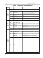
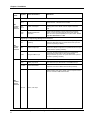
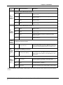
The Alarm Form C relay contacts change state when a MIC, AUX, or a DV (Digital Voice) message is active.
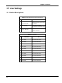
The AC Trouble Form C relay contacts change when primary power is missing or low. The System Trouble
Form C relay contacts change state when the panel goes into any trouble condition. For additional information,
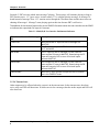
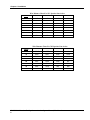
see Table 4-1. An AC Loss can be delayed 170 minutes before it is reported as a system trouble (SW2 – Position
2 set to ON).
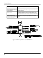
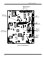
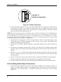
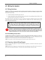
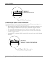
1. Connect the external alarm circuit to the proper Alarm (ALM) connections. See Figure 4-1, TB1, Section
1, for location.
2. Connect the external Trouble circuit to the proper Trouble (TRB) connections.
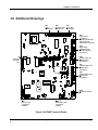
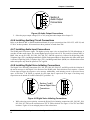
3. Connect the SP40S panel to earth ground, following the National Electrical Code and local codes for the
type of system being installed. Wire gauge selection of the earth ground wiring involves consideration of
all factors, including maximum allowable wire resistance and length. The panel is tied to earth ground by
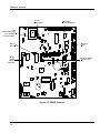
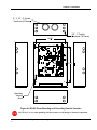
connecting the ground terminals to an earth ground. The location of the ground terminals within the
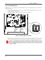
panel is shown in Figure 4-2.
CAUTION: Do not connect input voltage to any equipment until the field wiring has been
tested, inspected and approved.
4. Check the integrity of all field wiring. Confirm that the specified cable is installed, and that there is
continuity between required points (no open circuits), with no unwanted shorts to other conductors,
chassis, or earth ground.
a) Verify that the field wiring complies with the instructions of this manual and the detailed wiring
diagram prepared for this installation.
b) Ensure that no unwanted voltages are present on circuit conductors and ground.
c) Test all ungrounded connectors for electrical isolation from ground.
d) Measure and record the resistance of each NAC circuit. Conduct this test reversing polarity.
5. Perform Ground Fault Installation procedure as described in Section 4.7.
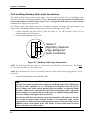
6. Calculate and install properly sized backup batteries as described in Section 4.8.3. The SP40S panel is
UL approved for 24VDC for a maximum of 33 Ah. Batteries greater than 12 Amp-Hour (Ah) are
required to be installed in a UL listed battery box. The enclosure can accommodate up to 12 Ah.
WARNING: Two different sources of power should be connected to this unit.
Disconnect both sources of power before servicing. Failure to disconnect both
power sources before servicing could result in serious injury, or death to you
and/or others.
WARNING: Always apply AC voltage before applying battery backup voltage.
Failure to do so may cause damage to the SP40S panel.
7. Perform System Checkout procedures as described in Section 4.6.
SP40S Multi-Function Facility Communication System Manual, Revision L
14