1
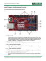
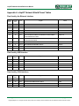
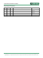
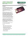
chipKIT™ Network Shield Board Reference Manual Revision: June 27, 2012 1300 NE Henley Court, Suite 3 Pullman, WA 99163 (509) 334 6306 Voice | (509) 334 6300 Fax Overview The chipKIT Network Shield is an input/output expansion board designed for use with the chipKIT Max32™. It provides the additional circuitry and connectors to allow the advanced communications features of the PIC32MX795F512L on the Max32 to be utilized. The Network Shield provides a 10/100 Mbps Ethernet PHY to allow connection to an Ethernet network. It provides the connectors and load switch to support use of the USB 2.0 OTG controller to implement USB device, USB host or OTG operation. It also provides two CAN transceivers and connectors to allow connection to two independent CAN networks. Connectors are provided to allow connection to two of the I2C busses supported by the Max32. In addition to the communications features, the Network Shield also adds a 256Kbit I2C EEPROM for non-volatile data storage and a 32.768Khz oscillator to allow use of the Real Time Clock/Calendar (RTCC) peripheral in the PIC32 microcontroller. The Network Shield is designed to the same form factor as the Max32 board. Features: SMSC LAN8720 10/100 Ethernet PHY RJ45 connector with integral magnetics USB Device and Host Connectors Two MCP2551 CAN Transceivers Two 12-pin header connectors for CAN Two I2C daisy chain connectors 256Kbit I2C EEPROM 32.768 Khz Oscillator Doc: 502-211 page 1 of 11 Copyright Digilent, Inc. All rights reserved. Other product and company names mentioned may be trademarks of their respective owners. chipKIT Network Shield Reference Manual chipKIT Network Shield Hardware Overview The Network Shield has the following hardware features: 1) USB Connectors The connector on the top of the board is a standard USB A type receptacle. This is used when the Max32/Network shield is used as a USB host. Immediately below this connector is a USB Micro-AB connector. Tis connector is used when the Max32/Network Shield is used as a USB device, or when using it as an On-The-Go (OTG) device. 2) Ethernet Connector with Integral Magnetics This connector is used to connect the Max32/Network Shield to an Ethernet network.. 3) JP4 – USB Host Connector Selection When the Max32/Network Shield is used as a USB host, this jumper is used to select which USB connector is being used. 4) J17 – Power Pass-through Connector This connector passes the power connector from the Max32 through the Network Shield board, and powers the Network Shield from the Max32. 5) J9 & J12 – Analog Signal Pass-Through Connectors These connectors pass the analog input pins on the Max32 through the Network Shield board. www.digilentinc.com page 2 of 11 Copyright Digilent, Inc. All rights reserved. Other product and company names mentioned may be trademarks of their respective owners. chipKIT Network Shield Reference Manual 6) CAN2 Connector This connector provides access to the signals for CAN2. 7) CAN1 Connector This connector provides access to the signals for CAN1. 8) Digital Signal Connector This connector provides most of the signals used by the Ethernet and USB interfaces from the Max32 board to the Network Shield board. The remaining signals are passed through the Network Shield. 9) J7 – I2C #1 Daisy Chain Connector This is a 2x4 pin header connector that provides access to the I2C signals SDA and SCL as well as power from the 3.3V power bus and ground. This can be used to extend the I 2C bus off of the board and to power external I2C device. Digilent has cables and a selection of I2C peripheral modules that can be accessed using this connector. 10) J7 – I2C #2 Daisy Chain Connector This is a 2x4 pin header connector that provides access to the I2C signals SDA and SCL as well as power from the 3.3V power bus and ground. This can be used to extend the I 2C bus off of the board and to power external I2C device. The jumpers for disabling the onboard pull-ups are adjacent to this connector. 11) Digital Signal Connectors Some of the signals used by the Network Shield are provided on these connectors. The rest of the signals are passed through the Network Shield. www.digilentinc.com page 3 of 11 Copyright Digilent, Inc. All rights reserved. Other product and company names mentioned may be trademarks of their respective owners. chipKIT Network Shield Reference Manual chipKIT Network Shield Hardware Description Introduction The following describes the hardware provided by the Network Shield and its use. Appendices at the end provide pin-out and connection tables. The Network Shield is designed to be used with the chipKIT Max32 board. When used in combination, the two boards provide the necessary supporting hardware and connectors to make use of all of the advanced communications and networking features of the PIC32MX795F512L microcontroller on the Max32. Ethernet Interface The Network Shield provides the ability to interface with 10Mbps or 100Mbps Ethernet networks. The PIC32MX795 microcontroller on the chipKIT Max32 board contains a 10/100 Ethernet Medium Access Controller (MAC). The Network Shield provides an SMSC LAN8720 Ethernet Physical Layer Transceiver (PHY). Together, the MAC and PHY provide a complete 10/100 Ethernet interface. The RJ45 connector, J1, provides the physical connection to an Ethernet network using a standard Ethernet cable. When the Ethernet controller is enabled in the PIC32 microcontroller, it takes over the use of a number of the microcontroller pins. All of the signals from these pins are taken from connector J10 on the Network Shield (connector J8 on the Max32). Three of these signals are also shared with connector J7 on the Max32 and are analog pins A11, A12, and A13. When the Ethernet interface on the Network Shield is being used, these pins are not available for other use, and nothing should be connected to them to avoid interference with the operation of the Ethernet interface. www.digilentinc.com All devices on an Ethernet network must have a unique address. This address is used to direct packets on the network to a specific device and to identify the device that originated a packet. An Ethernet MAC uses a 48-bit address value, commonly called the ‘MAC Address’. These address values are globally unique to ensure that no two devices on a network can have conflicting addresses. MAC addresses are assigned by the IEEE. The address to use with the Network Shield is printed on a sticker attached to the bottom of the board. The address is a twelve digit hexadecimal number of the form: 00183Exxxxxx, where xxxxxx represents six hexadecimal digits. This value is used to initialize the Ethernet Controller MAC Station Address registers in the Ethernet controller of the PIC32MX795 microcontroller. In order to connect to and operate with an Ethernet network, the PIC32 microcontroller must be running network protocol stack firmware. Normally, the TCP/IP (Transmission Control Protocol/Internet Protocol) network protocol is used and “TCP/IP Stack” software will be used. The Ethernet library provided for use with the Network Shield board provides the necessary stack support for use of the chipKIT Max32/Network Shield from within the MPIDE programming environment. If the board is being used outside the MPIDE programming environment, The Microchip Applications Library, available for download from the Microchip web site provides full protocol stack support compatible with the PIC32MX795 MAC and the LAN8720 PHY. Microchip also provides numerous example programs illustrating the use of their network protocol stack for various applications. When not using the either the chipKIT Ethernet library or the Microchip network protocol stack, refer to the manufacturer documentation for the PIC32MX795 and LAN8720, plus network page 4 of 11 Copyright Digilent, Inc. All rights reserved. Other product and company names mentioned may be trademarks of their respective owners. chipKIT Network Shield Reference Manual protocol documentation, for operation of the Ethernet interface. The PIC32MX795 microcontroller provides two alternate sets of pins that can be used to connect the MAC to the external PHY. It also provides two alternate standard MAC/PHY interface signaling conventions. The chipKIT Max32/Network Shield are designed to use the standard (not the alternate) pins, and to use the RMII (not the MII) interface signaling convention. These options are selected using the configuration variables in the PIC32 microcontroller and are specified using the #pragma config statement. To enable the Ethernet controller in the correct configuration, the following statements must appear in the main program module: #pragma config FETHIO=ON #pragma config FMIIEN=OFF The boot loader in the chipKIT Max32 board sets this configuration by default. When using the Network Shield within the MPIDE environment no additional work is necessary. When using it outside the MPIDE environment, these configuration settings must be made. The LAN8720 PHY has a reset signal, labeled NRST in the schematic, that is used to reset the PHY. This signal is connected to the INT2/RE9 pin on the PIC32 microcontroller. This pin is chipKIT digital pin 7 on the Max32 board. The NRST signal is active low. Configure the microcontroller pin as an output and drive it low to reset the PHY, or drive it high to allow the PHY to come out of reset and begin operation. The NRST signal is pulled low on the Network Shield board, so that the PHY is held in reset by default. To allow the PHY to operate, this pin must be driven high. This reset operation is not part of the Microchip network protocol stack, and so driving NRST high must be done before initializing the Microchip network stack. When using the chipKIT Ethernet library for the Network Shield, this is done automatically by the library. www.digilentinc.com USB Interface The PIC32MX795 microcontroller on the Max32 contains a USB 2.0 Compliant, Full Speed Device and On-The-Go (OTG) controller. This controller provides the following features: USB full speed host and device support Low speed host support USB OTG support Endpoint buffering anywhere in system RAM Integrated DMA to access system RAM and Flash memory. Connector J4 on the top left side of the board is a standard USB type A receptacle. This connector will generally be used when the Max32/Network Shield has been programmed to operate as a USB host. The USB device is connected either directly, or via cable to this connector. Connector J2, on the bottom left side of the Network Shield board is the Device/OTG connector. This is a standard USB micro-AB connector. Connect a cable with a micro-A plug (optionally available from Digilent) from this connector to an available USB port on a PC or USB hub for device operation. When the USB controller in the PIC32 microcontroller on the Max32 board is in use, it takes over the use of several of the pins. The signals provided by these pins appear on connector J13 on the Network Shield (connector J9 on the Max32). Two addition signals are used, when doing USB hosting. These signals appear on AN5 and digital pin 2. These pins are not available when using the USB interface. When operating as a USB device, the chipKIT Max32/Network Shield will normally be a self powered device. To operate as a self powered device, an external power supply should be connected to the external power connector, J2 on the Max32 board. If the external power supply is a regulated 5V supply, jumper JP1 on page 5 of 11 Copyright Digilent, Inc. All rights reserved. Other product and company names mentioned may be trademarks of their respective owners. chipKIT Network Shield Reference Manual the Max32 should be set in the BYP position to bypass the on-board 5V regulator. The Max32/Network Shield can also be operated as a self powered device powered by the USB connector, J1, on the Max32. This is the connector used by the USB Serial converter. When operated this way, the Max32/Network Shield will be a bus powered device from the perspective of the USB port connected to J1, and a self powered device from the perspective of the port connected to the USB connector J2 on the Network Shield. Operation of the Max32/Network Shield as a bus powered device is possible although not recommended in most cases. The USB bus voltage from USB connector J2 appears on pin 1 of jumper JP4. Remove the shorting block from JP4, and jumper from pin 1 to any point on the board that connects to the 5V bus, VCC5V0. The VCC5V0 bus can be accessed from power connector J17, pin 3. It can also be accessed from either pin of J14, the uppermost two pins on the connector on the right edge of the board. When operating the board in this way, be aware that if the USB serial converter on the Max32 is connected to a live USB port, the 5V power supplies of the two USB ports (the one connected to the Max32 and the one connected to the Network Shield) will be shorted together. If these are not the same power supply (i.e. both USB ports are on the same PC), one or both USB ports and/or the Max32/Network Shield may be damaged. When operating as a USB host, the Max32/Network Shield should be externally powered. Connect a power supply to the external power connector, J2, on the Max32. If the external supply is a regulated 5V supply, place JP1 on the Max32 in the BYP position to bypass the 5V regulator. The power supply used must be able to supply enough current to power both the Max32/Network Shield, and the attached USB device, as the Max32/Network Shield provides power to the attached USB device when operating as a host. www.digilentinc.com Jumper JP4 on the Network Shield is used to route power to the host connector being used. Place the shorting block in the “A” position when using the standard USB type A (host) Connector, J4. Place the shorting block in the “MICRO” position for use with the USB microAB (OTG) connector, J2. When operating as a USB host, the PIC32MX795 microcontroller controls application of power to the connected device via the VBUSON control pin (labeled VBUSON in the schematic). Bus power is applied to the USB bus by driving the VBUSON pin high. Power is removed from the bus by driving the VBUSON pin low. The VBUSON pin is accessed via bit 3 of the U1OTGCON register. The VBUSON signal is shared with same microcontroller pin as analog input A5 and digital pin 59. The VBUSON pin drives the enable input of a TPS2051B Current-Limited Power Distribution Switch to control the application of USB power to the host connector. This switch has overcurrent detection capability and provides an over-current fault indication by pulling the signal USBOC low. The over-current output pin can be monitored via the INT1/RE8 pin on the PIC32MX795 microcontroller. This signal appears on connector J14, pin 5 on the Max32 board, and is chipKIT digital pin 2. Details about the operation of the TPS2051B can be obtained from the data sheet available at the Texas Instruments web site. The VBUSON signal is shared with same microcontroller pin as analog input A5 and digital pin 59. This pin is not available for other uses when operating as a USB host. If the Max32/Network Shield is not being used as a USB host, the use of A5/pin 59 can be recovered by cutting the trace on the bottom of JP3. USB Host capability can be restored by soldering a two pin header to JP3 and installing a shorting block. The PIC32 USB controller can be accessed using the chipKIT USB libraries for use within the MPIDE environment. page 6 of 11 Copyright Digilent, Inc. All rights reserved. Other product and company names mentioned may be trademarks of their respective owners. chipKIT Network Shield Reference Manual When using the Max32/Network Shield outside the MPIDE environment, the Microchip Application Library provides USB stack code that can be used with the Max32/Network Shield. There are reference designs available on the Microchip web site demonstrating both device and host operation of PIC32 microcontrollers. These reference designs are suitable to use for developing USB firmware for the Max32/Network Shield. CAN Interfaces The Controller Area Network (CAN) is a control networking standard originally developed for use in automotive systems, but has since become a standard used in various industrial control and building automation networking applications as well. The PIC32MX795 microcontroller on the Max32 contains two independent CAN network controllers. These CAN controllers in combination with two Microchip MCP2551 CAN transceivers on the Network Shield allow the Max32/Network Shield to operate on one or two independent CAN networks. When not using the MPIDE environment, refer to the PIC32MX7XX data sheet and the PIC32 Family Reference Manual, plus CAN network documentation for information on operation of the CAN controllers and CAN networking in general. The PIC32MX795 microcontroller provides two sets of pins that can be used to connect the CAN controllers to the external transceivers. The Max32/Network Shield is designed to use the alternate (not the standard) pins. This selection is made using the configuration variables in the microcontroller, set using a #pragma config statement. To select the use of the alternate interface pins, the following statement must appear in the main program module: #pragma config FCANIO=OFF www.digilentinc.com When using the Max32/Network Shield within the MPIDE environment, the boot loader on the Max32 boards sets this configuration automatically, so nothing needs to be done in this case. When using the boards outside the MPIDE environment, this configuration setting is required. The pins on the PIC32MX795 microcontroller used by signals for the CAN1 controller to connect to its transceiver are shared with two of the signals for UART3B and SPI port 3A. These signals appear on pins 14 & 15 of connector J4 on the Max32 board. To recover the use of these pins if both CAN networks are not needed, jumpers JP1 and JP5 are provided on the Network Shield. There are cut-able traces on the bottom of the board between the pins of JP1 and JP5. Cut these traces to disconnect the transceiver for CAN1. To restore the connection, load two pin headers for JP1 and JP5 and install shorting blocks on the two jumpers. The pins on the PIC32MX795 microcontroller used by the signals for CAN2 appear on connector J13 on the Network Shield (connector J9 on the Max32), pins 15 and 16. These are digital pins 22 and 23. These pins are not available for other use when using CAN2. There is no standard connector for use with CAN networks. The Network Shield provides two 2x6 pin header connectors for access to the CAN signals. Connector J3 provides access to the signals for the CAN1 network controller, and connector J5 provides access to the signals for CAN2. Refer to the schematic for the Network Shield board or the tables at the end of this document for information on the connectors and signals. Digilent 6-pin or 2x6 to dual 6-pin cables can be used to daisy chain Digilent boards together in a CAN network. A Digilent 6-Pin cable in combination with a Digilent PmodCON1 Screw Terminal Connector module can be used to connect the Max32/Network Shield to other network wiring configurations. page 7 of 11 Copyright Digilent, Inc. All rights reserved. Other product and company names mentioned may be trademarks of their respective owners. chipKIT Network Shield Reference Manual The CAN network standard requires that the nodes at each end of a network provide 120 ohm termination. The Network Shield provides the termination resistors and jumpers to enable/disable them depending on the location of the board in the network. Jumper JP6 is used to enable/disable the termination resistor for the CAN1 network, and JP8 is used to enable/disable the termination resistor for CAN2. Install a shorting block on the jumper pins to enable the termination resistor, or remove the shorting block to disable the termination resistor. 2 I C Busses and Connectors The Inter-Integrated Circuit (I2CTM) Interface provides a medium speed (100K or 400K bps) synchronous serial communications bus. The I2C interface provides master and slave operation using either 7 bit or 10 bit device addressing. Each device is given a unique address, and the protocol provides the ability to address packets to a specific device or to broadcast packets to all devices on the bus. Refer to the Microchip PIC32MX7XX Data Sheet and the PIC32 Family Reference Manual for detailed information on configuring and using the I2C interface. The PIC32MX795 microcontroller on the Max32 provides for up to five independent I2C interfaces. The Network Shield is designed to provide access to two of these interfaces I2C #1 (SCL1, SDA1) and I2C #2 (SCL2, SDA2). I2C #1 is the bus accessed through the standard chipKIT Wire library. There are two sets of connectors on the board for access to the two I2C ports. Connector J7 provides access to I2C port #1 while connector J6 provides access to I2C port #2. The user should note that external interrupt 3 and SCL1 share the same pin on the PIC32MX795. External interrupt 4 and SDA1 also share the same pin. Therefore, external interrupts 3 and 4 should not be used simultaneously with I2C bus #1. www.digilentinc.com One I2C device is provided on the Network Shield. This is a 256Kbit EEPROM connected to the I2C #1 bus. I2C Connectors: Connectors J6 and J7 can be used to extend the I2C busses off of the board to connect to external I2C devices. These are standard 2x4 pin header connectors with 0.100” spaced pins. They provide access to the I2C signals, SCL and SDA, plus VCC3V3 and ground. The VCC3V3 can be used to power external I2C devices. The I2C bus uses open collector drivers to allow multiple devices to drive the bus signals. This means that pull-up resistors must be provided to supply the logic high state for the signals. The Network Shield provides 2.2Kohm pull-up resistors on I2C #1. As I2C #1 is the bus with the EEPROM, these pull-up resistors are permanently connected. Jumpers JP9 & JP12 are provided to allow I2C #1 to be disconnected from the Network Shield, if it not being used and is interfering with the use of the associated pins. There are cut-able traces on the underside of the board between the pins of these jumpers. Cut these traces to disconnect SCL1 and SDA1 from the Network Shield. To restore the connection, load two pin headers for JP9 and JP12 and install shorting blocks. If this is done, it is still possible to access the on-board EEPROM by connecting SCL and SDA from I2C #2 by installing jumper wires between connector J6 and J7. The EEPROM will then appear on I2C bus #2. The logic high pull-up for I2C #2 is provided by sourcing current mirrors instead of resistors. These current mirrors source approximately 1.7mA. The use of current mirrors provides faster rise times on the I2C signals and provides the ability to drive longer cable runs reliably than would be the case with simple pull-up resistors. Generally, only one set of pull-ups are used on the bus. Jumpers JP10 and JP11 can be used to disable the on-board pull-ups on I2C #2 if a page 8 of 11 Copyright Digilent, Inc. All rights reserved. Other product and company names mentioned may be trademarks of their respective owners. chipKIT Network Shield Reference Manual different value is needed or some other device on the bus is providing the pull-ups or if I2C #2 isn’t being used and the pull-ups are interfering with the use of the pins. The on-board pull-ups are enabled by install shorting blocks on JP10 and JP11. Removing the shorting blocks disables the pull-ups. Digilent has several small I/O modules available that can be connected using the I2C connector. These include a 3-axis accelerometer, 4-channel, 12-bit A/D converter, serial character LCD panel, 3-axis gyroscope, real-time clock/calendar, and I/O expander. EEPROM: A 256Kbit (32Kbyte), I2C EEPROM is provided using a Microchip 24LC256. This EEPROM, IC5, is located on the bottom of the board. The EEPROM is on I2C bus #1, and its seven bit I2C device address is ‘1010000’. Digilent provides a library for accessing this EEPROM. The library is available on the Digilent web site and in the third party libraries repository on github. For complete technical documentation on the 24LC256, refer to the data sheet available on the Microchip web site. 32.768Khz Oscillator A 32.768Khz oscillator is provided to use as a clock source for the Real Time Clock/Calendar (RTCC) peripheral in the PIC32MX796 microcontroller on the Max32 board. The output of this oscillator connects to pin 12 or connector J11. On the Max32 board, this signal connects to signal RC13, which connects to pin 73 on the PIC32 microcontroller. This pin provides the secondary oscillator input, which can be used to clock the RTCC in the PIC32 microcontroller. www.digilentinc.com page 9 of 11 Copyright Digilent, Inc. All rights reserved. Other product and company names mentioned may be trademarks of their respective owners. chipKIT Network Shield Reference Manual Appendix A: chipKIT Network Shield Pinout Tables Pins Used by the Ethernet Interface chipKIT Pin # PIC32 Pin # Pin Signal Notes 46 88 J10-8 C1TX/ETXD0/PMD10/RF1 ETXD0 45 87 J10-9 C1RX/ETXD1/PMD11/RF0 ETXD1 47 83 J10-7 ETXEN/PMD14/CN15/RD6 ETXEN 48 68 J10-6 RTCC/EMDIO/AEMDIO/IC1/RD8 EMDIO 49 71 J10-5 EMDC/AEMDC/IC4/PMCS1/PMA14/RD11 EMDC 53 14 J10-1 ERXCLK/AERXCLK/EREFCLK/AEREFCLK/SS2A/U2BRX/ U2ACTS/PMA2/CN11/RG9 EREFCLK 43 12 J10-11 ERXDV/AERXDV/ECRSDV/AECRSDV/SCL2A/SDO2A UATX/PMA3/CN10/RG8 ECRSDV 40 35 J10-14 AN11/ERXERR/AETXERR/PMA12/RB11 ERXERR 42 41 J10-12 AN12/ERXD0/AECRS/PMA11/RB12 ERXD0 41 42 J10-13 AN13/ERXD1/AECOL/PMA10/RB13 ERXD1 7 19 J11-15 AERXD0/INT2/RE9 NRST Pins Used by USB Interface chipKIT Pin # PIC32 Pin # Pin Signal 27 57 J13-11 USBD+/RG2 26 56 J13-12 USBD-/RG3 25 51 J13-13 USBID/RF3 A5/59 20 J9-6 AN5/C1IN+/VBUSON/CN7/RB5 2 18 J11-5 AERXD0/INT1/RE8 Notes Pins Used by CAN Interfaces chipKIT Pin # PIC32 Pin # Pin 14 39 J16-8 AC1TX/SCK3A/U3BTX/U3ARTS/RF13 CAN1 15 40 J16-7 AC1RX/SS3A/U3BRX/U3ACTS/RF12 CAN1 22 7 J10-16 T3CK/AC2TX/RC2 CAN2 23 8 J10-15 T4CK/AC2RX/RC3 CAN2 www.digilentinc.com Signal Notes page 10 of 11 Copyright Digilent, Inc. All rights reserved. Other product and company names mentioned may be trademarks of their respective owners. chipKIT Network Shield Reference Manual Pins Used by I2C Interfaces chipKIT Pin # PIC32 Pin # Pin 66 21 J16-1 AETXCLK/SCL1/INT3/RA14 I2C1 – also attached to EXT INT 3 67 20 J16-2 AETXEN/SDA1/INT4/RA15 I2C1 – also attached to EXT INT 4 58 12 J8-9 SCL2/RA2 I2C2 59 13 J8-11 SDA2/RA3 I2C2 www.digilentinc.com Signal Notes page 11 of 11 Copyright Digilent, Inc. All rights reserved. Other product and company names mentioned may be trademarks of their respective owners.