1
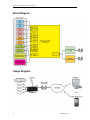
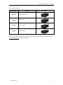
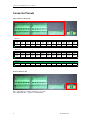
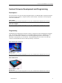
User Manual Connect Tech Inc. 42 Arrow Road Guelph, Ontario N1K 1S6 Tel: Toll: Fax: Email: Web: 519-836-1291 800-426-8979 (North America only) 519-836-4878 [email protected] [email protected] www.connecttech.com CTIM-000148 Revision 0.02 - August 20, 2012 Connect Tech RoadWarrior User Manual Limited Lifetime Warranty Connect Tech Inc. provides a lifetime warranty for all of our products. Should this product, in Connect Tech Inc.’s opinion, fail to be in good working order during the warranty period, Connect Tech Inc. will, at its option, repair or replace this product at no charge, provided that the product has not been subjected to abuse, misuse, accident, disaster or non Connect Tech Inc. authorized modification or repair. You may obtain warranty service by delivering this product to an authorized Connect Tech Inc. business partner or directly to Connect Tech Inc. along with proof of purchase. Product returned to Connect Tech Inc. must be pre-authorized by Connect Tech Inc. with an RMA (Return Material Authorization) number marked on the outside of the package and sent prepaid, insured and packaged for safe shipment. Connect Tech Inc. will return this product by prepaid ground shipment service. The Connect Tech Inc. lifetime warranty is defined as the serviceable life of the product. This is defined as the period during which all components are available. Should the product prove to be irreparable, Connect Tech Inc. reserves the right to substitute an equivalent product if available or to retract lifetime warranty if no replacement is available. The above warranty is the only warranty authorized by Connect Tech Inc. Under no circumstances will Connect Tech Inc. be liable in any way for any damages, including any lost profits, lost savings or other incidental or consequential damages arising out of the use of, or inability to use, such product. Copyright Notice The information contained in this document is subject to change without notice. Connect Tech Inc. shall not be liable for errors contained herein or for incidental consequential damages in connection with the furnishing, performance, or use of this material. This document contains proprietary information that is protected by copyright. All rights are reserved. No part of this document may be photocopied, reproduced, or translated to another language without the prior written consent of Connect Tech Inc. Copyright 2012 by Connect Tech Inc. Trademark Acknowledgment Connect Tech Inc. acknowledges all trademarks, registered trademarks and/or copyrights referred to in this document as the property of their respective owners. Not listing all possible trademarks or copyright acknowledgments does not constitute a lack of acknowledgment to the rightful owners of the trademarks and copyrights mentioned in this document. 2 Revision 0.02 Connect Tech RoadWarrior User Manual Table of Contents Limited Lifetime Warranty ............................................................................................................................................... 2 Copyright Notice............................................................................................................................................................... 2 Trademark Acknowledgment ............................................................................................................................................ 2 Table of Contents .............................................................................................................................................................. 3 Revision History ............................................................................................................................................................... 3 Customer Support Overview ............................................................................................................................................. 4 Contact Information .......................................................................................................................................................... 4 Introduction....................................................................................................................................................................... 5 Product Features ............................................................................................................................................................... 5 Block Diagram .................................................................................................................................................................. 6 Usage Diagram ................................................................................................................................................................. 6 Connector Pinouts ............................................................................................................................................................. 8 Custom Firmware Development and Programming .......................................................................................................... 9 Development ........................................................................................................................................ 9 Programming ...................................................................................................................................... 9 Microcontroller Mappings ...............................................................................................................................................10 Revision History Revision Date Author(s) Change(s) 0.00 01-03-2012 PD Initial Manual Revision Created 0.01 02-28-2012 HJ Firmware configuration and description added. 0.02 08-17-2012 PD Added Dimensioned Drawings and Power Consumption Details Revision 0.02 3 Connect Tech RoadWarrior User Manual Customer Support Overview If you experience difficulties after reading the manual and/or using the product, contact the Connect Tech Inc. reseller from which you purchased the product. In most cases the reseller can help you with product installation and difficulties. In the event that the reseller is unable to resolve your problem, our highly qualified support staff can assist you. Our support section is available 24 hours a day, 7 days a week on our website at: www.connecttech.com/sub/support/support.asp. See the contact information section below for more information on how to contact us directly. Our technical support is always free. Contact Information We offer three ways for you to contact us: Mail/Courier You may contact us by letter at: Connect Tech Inc. Technical Support 42 Arrow Road, Guelph, ON Canada N1K 1S6 Email/Internet You may contact us through the Internet. Our email and URL addresses on the Internet are: [email protected] [email protected] www.connecttech.com Note: Please go to the Download Zone or the Knowledge Database in the Support Center on the Connect Tech Inc. website for product manuals, installation guides, device driver software and technical tips. Submit your technical support questions to our customer support engineers via the Support Center on the Connect Tech Inc. website. Telephone/Facsimile Technical Support representatives are ready to answer your call Monday through Friday, from 8:30 a.m. to 5:00 p.m. Eastern Standard Time. Our numbers for calls are: Telephone: Telephone: Facsimile: 4 800-426-8979 (North America only) 519-836-1291 (Live assistance available 8:30 a.m. to 5:00 p.m. EST, Monday to Friday) 519-836-4878 (online 24 hours) Revision 0.02 Connect Tech RoadWarrior User Manual Introduction Connect Tech’s RoadWarrior enables remote monitoring, controlling and collecting of data from multiple I/O interfaces through a wireless cellular data link or Low Earth Orbit (LEO) satellite. RoadWarrior can be controlled from any Internet connected device. This product is designed for rugged mobile, mission-critical and industrial strength applications that require enhanced wireless M2M (machine-to-machine) connectivity. RoadWarrior can be configured to operate on any existing cellular network standard and frequency bands today, with drop-in replacement upgradeability to operate on future cellular networks. RoadWarrior also has the capability of operating on LEO satellite networks. With a wide range of interfaces including RS-232, RS-485, CAN, GPS, Bi-directional GPIO, High Voltage Isolated GPIO and ADC’s, RoadWarrior is ideal for many remote or mobile application environments including transportation and military applications. Product Features Specification Cellular Details Cellular Networks: o HSPA/EV-DO/UMTS/EDGE/GPRS/CDMA Frequency Bands: o 3G/3.5G: 850/1900/2100 MHz o 2G/2.5G: 850/900/1800/1900 MHz o Drop-in replacement for future mobile telephony o standards, networks and frequency band GPS NMEA-0183 V3.01 compliant GPS message Satellite Optional satellite communication capabilities via Low Earth Orbit (LEO) Satellites Serial 2 x RS-232, 2 x RS-485 CAN 2 x CAN 2.0b GPIO 16 bits +3.3V or +5V bi-direction GPIO 3 bits optically isolated outputs (0 ~ +40V DC) 3 bits optically isolated inputs (0 ~ +40V DC) Connectors 2.5mm pitch terminal block header Main Control Unit Microchip PIC32 Microcontroller (PIC32MX775) which can be optionally configured end-users application code Enclosure Rugged extruded aluminum enclosure with mounting flanges. 5.275” (width) x 2.000” (height) x 6.000” (length) Input Power +9 to +30V DC (ability to handle standard vehicle power) Operating Environment Industrial Temperature: -40ºC to 85ºC (-40ºF to 185ºF) Revision 0.02 5 Connect Tech RoadWarrior User Manual Block Diagram Usage Diagram 6 Revision 0.02 Connect Tech RoadWarrior User Manual Part Number Information Part Number Features RDG001 GSM / GPRS Model RDG002 HSPA Model RDG003 EV-DO Model RDG004 CDMA Model Board Image To order any of these part numbers or to inquire about the other available ordering options please contact [email protected] for further information. Revision 0.02 7 Connect Tech RoadWarrior User Manual Connector Pinouts I/O Connectors (P6, P7, P4) P6 (Left Connector) A1 GPIO0 B1 GPIO11 A2 GPIO1 B2 GPIO12 A3 GPIO2 B3 GPIO13 A4 GPIO3 B4 GPIO14 A5 GPIO4 B5 GPIO15 A6 GPIO5 B6 GND A7 GPIO6 B7 ANALOG_CH0 A8 GPIO7 B8 ANALOG_CH1 A9 GPIO8 B9 ANALOG_CH2 A10 GPIO9 B10 ANALOG_CH3 A11 A12 GPIO10 GND B11 B12 ANALOG_VREF+ ANALOG_VREF- P7 (Middle Connector) A1 A2 A3 A4 485_UART1_TX+ 485_UART1_TX- 485_UART1_RX+ 485_UART1_RXB1 B2 B3 B4 HV_OUT1 HV_OUT1_V+ HV_OUT1_VHV_OUT2 A5 GND B5 HV_OUT2_V+ A6 A7 A8 A9 485_UART2_TX+ 485_UART2_TX- 485_UART2_RX+ 485_UART2_RXB6 B7 B8 B9 HV_OUT2_VHV_IN0+ HV_IN0HV_IN1+ A10 HV_OUT0 B10 HV_IN1- A11 HV_OUT0_V+ B11 HV_IN2+ A12 HV_OUT0_VB12 HV_IN2- A10 CAN2_LOW A11 CAN2_HIGH A12 CAN2_GND P4 (Right Connector) A1 232_UART1_RX A2 232_UART1_TX A3 GND A4 232_UART2_RX A5 232_UART2_TX A6 GND A7 CAN1_LOW A8 CAN1_HIGH A9 CAN1_GND Power Connector (P3) Pin 1 (Left Side Pin) = Positive Terminal (+9 to +30V) Pin 2 (Right Side Pin) = Negative Terminal (GND) 8 Revision 0.02 Connect Tech RoadWarrior User Manual Custom Firmware Development and Programming Development All of the firmware code can be developed using MicroChips’s free MPLAB IDE in conjunction with their Full-featured ANSI-compliant C compiler for PIC32 microcontrollers. Information on the development tools can be found below. MPLAB IDE: http://www.microchip.com/stellent/idcplg?IdcService=SS_GET_PAGE&nodeId=1406&dDocName=en019469 MPLAB C Compiler: http://www.microchip.com/stellent/idcplg?IdcService=SS_GET_PAGE&nodeId=2615&dDocName=en532454 Programming Programming and configuration will can done using any of MicroChip’s PIC32 Debugging and emulation tools. These include the MPLAB ICD3 device or the MPLAB REAL ICE device, information on these products can be found below. With PIC devices the main programming interface is done through MicroChip’s own propretary two wire interface. The programming tools will connect via an RJ 6-Pin connector on the RoadWarrior labeled “ICD Programming” at location P1. MPLAB ICD3 (Recommended) Device List Price: ~$200 Website Link: http://www.microchip.com/stellent/idcplg?IdcService=SS_GET_PAGE&nodeId=1406&dDocName=en537580 MPLAB REAL ICE Device List Price: ~$500 Website Link: http://www.microchip.com/stellent/idcplg?IdcService=SS_GET_PAGE&nodeId=1406&dDocName=en028120 Revision 0.02 9 Connect Tech RoadWarrior User Manual Microcontroller Mappings Below is a complete listing of all of the peripheral interconnect to the microcontroller. PIC32 Name Signal Name (+3.3V or +5V) GPIO PORTA0 GPIO0 PORTA1 GPIO1 PORTA2 GPIO2 PORTA3 GPIO3 PORTA4 GPIO4 PORTA5 GPIO5 PORTA6 GPIO6 PORTA7 GPIO7 PORTD0 GPIO8 PORTD1 GPIO9 PORTD2 GPIO10 PORTD3 GPIO11 PORTD4 GPIO12 PORTD5 GPIO13 PORTD6 GPIO14 PORTD7 GPIO15 PORTB8 GPIO0-7 Direction PORTB9 GPIO8-15 Direction Notes 0 = Low | 1 = High 0 = Low | 1 = High 0 = Low | 1 = High 0 = Low | 1 = High 0 = Low | 1 = High 0 = Low | 1 = High 0 = Low | 1 = High 0 = Low | 1 = High 0 = Low | 1 = High 0 = Low | 1 = High 0 = Low | 1 = High 0 = Low | 1 = High 0 = Low | 1 = High 0 = Low | 1 = High 0 = Low | 1 = High 0 = Low | 1 = High 0 = sets GPIO Pins 0-7 as INPUTS | 1 = sets GPIO Pins 0-7 as OUTPUTS 0 = sets GPIO Pins 8-15 as INPUTS | 1 = sets GPIO Pins 8-15 as OUTPUTS USER LEDs PORTD8 PORTD9 PORTD10 PORTD11 PORTD12 PORTD13 USER_LED0 USER_LED1 USER_LED2 USER_LED3 USER_LED4 USER_LED5 Located at front at edge of board Located at front at edge of board Located on PCB Located on PCB Located on PCB Located on PCB Isolated GPIO PORTE0 PORTE1 PORTE2 PORTE4 PORTE5 PORTE6 HV_OUT0 HV_OUT1 HV_OUT2 HV_IN0 HV_IN1 HV_IN2 Isolated GPIO Output Bit-0 Isolated GPIO Output Bit-1 Isolated GPIO Output Bit-2 Isolated GPIO Input Bit-0 Isolated GPIO Input Bit-1 Isolated GPIO Input Bit-2 UARTs UART1A UART2A UART3A UART3B UART2B USM_UART 232_UART1 232_UART2 485_UART1 485_UART2 This UART is connected to the cellular modem (TX, RX, RTS, CTS) RS-232 Port #1 (TX, RX only) RS-232 Port #2 (TX, RX only) RS-485 Port #1 (TX, RX only) RS-485 Port #2 (TX, RX only) CAN CAN1 CAN2 CAN1 CAN2 CAN Controller #1 CAN Controller #2 ADC AN0 AN1 AN2 AN3 VREFVREF+ ANALOG_CH0 ANALOG_CH1 ANALOG_CH2 ANALOG_CH3 ANALOG_VREFANALOG_VREF+ ADC Input ADC Input ADC Input ADC Input ADC VREFADC VREF+ MISC PORTC1 USM_RESET# Cellular Modem Reset Signal 10 Revision 0.02 Connect Tech RoadWarrior User Manual Preloaded Firmware in RoadWarrior Target Audience The RoadWarrior User Manual assumes that the reader is familiar with programming using the C language, and the hardware platform. It is also assumes that the reader is familiar with the target operating system and related C development tools such as Borland, Visual Studio, or the GCC compiler. Configuration of Cell Modem To configure cell modem, connect UART1 to a serial port; use hyperterminal, putty, etc. for Windows and Minicom for Linux to communicate with the cell modem. Power on the cell modem. The firmware will emit the character ‘*’ for 30 seconds through UART1 while the firmware scans for a ‘password’ as login authentication. Once the password is entered from the application, (hyperterminal, putty etc.) the login prompt ‘>’ will appear. From this point forward, any character entered will be sent to the cell modem, and any character received from cell modem will sent to the application by UART1. To configure the cell, use ‘AT’ commands. Please refer to the following three documents to configure the modem: 1. 2. 3. Universal_IP_Ref_Guide_S000457I.pdf HSPA_AT_Command_Ref_Guide_S000483A.pdf GPRS_AT_Command_Ref_Guide_S000463C.pdf For the latest manuals, please visit www.multitech.com. Once the configuration is complete, enter: ‘Ctrl-q’ (0x11) This command will exit the cell modem configuration mode and the normal firmware booting will continue. Revision 0.02 11 Connect Tech RoadWarrior User Manual TCP Socket Configuration You will need to assign IP address for the modem that you get from the carrier service provider and a valid TCP port. Use #TCPSERV for setting IP address and #TCPPORT for setting TCP port. See ‘Chapter 5 – TCP Commands for All Universal IP Devices’ of Universal_IP_Ref_Guide_S000457I.pdf. Once the modem is configured for TCP server, the socket application can connect to the modem and send commands to the firmware to perform various operations on GPIO, ADC, RS-232/485 UARTs, CAN and GPS. Packet and Command Response All command packet will have to be terminated by ‘<’ character and all response packets will be terminated by the same character followed by ‘\r\n\>’. The general command format is as follows: 12 If the command has no configuration data then the following command format will apply: Command< If the command has configuration data then the following command format will apply: Command:’configuration data’< If the response has no data then the following response format will apply: Command:’status’< Where status is ‘DONE’ or ‘FAIL’ If the response has data then the following response format will apply: Command:’data’< Revision 0.02 Connect Tech RoadWarrior User Manual GPIO - Non-Isolated GPIO PORTA0 to PORTA7 are configured as output and PORTD0 to PORTD7 are configured as input. The following commands will read input from PORTD0 to PORTD7: GPIOA1R< read PORTD0 GPIOA2R< read PORTD1 GPIOA3R< read PORTD2 GPIOA4R< read PORTD3 GPIOA5R< read PORTD4 GPIOA6R< read PORTD5 GPIOA7R< read PORTD6 GPIOA8R< read PORTD7 The response will be one byte ‘0’ for low and ‘1’ for high. For example, “GPIOA2R:1<” means PORTD1 is high. The following commands will set output low from PORTA0 to PORTA7: GPIOB1W0< set low PORTA0 GPIOB2W0< set low PORTA1 GPIOB3W0< set low PORTA2 GPIOB4W0< set low PORTA3 GPIOB5W0< set low PORTA4 GPIOB6W0< set low PORTA5 GPIOB7W0< set low PORTA6 GPIOB8W0< set low PORTA7 The following commands will set output high from PORTA0 to PORTA7: Revision 0.02 GPIOB1W1< set high PORTA0 GPIOB2W1< set high PORTA1 GPIOB3W1< set high PORTA2 GPIOB4W1< set high PORTA3 GPIOB5W1< set high PORTA4 GPIOB6W1< set high PORTA5 GPIOB7W1< set high PORTA6 GPIOB8W1< set high PORTA7 13 Connect Tech RoadWarrior User Manual Isolated GPIO PORTE0 to PORTE2 are configured as output and PORTE4 to PORTE6 are configured as input. The following commands will read input from PORTE4 to PORTE6: GPIOC1R< read PORTE4 GPIOC2R< read PORTE5 GPIOC3R< read PORTE6 The following commands will set output low from PORTE0 to PORTE2: GPIOD1W0< set low PORTE0 GPIOD2W0< set low PORTE1 GPIOD3W0< set low PORTE2 The following commands will set output high from PORTE0 to PORTE2: 14 GPIOD1W1< set high PORTE0 GPIOD2W1< set high PORTE1 GPIOD3W1< set high PORTE2 Revision 0.02 Connect Tech RoadWarrior User Manual ADC The following command will read values from ADC1, ADC2 ADC3 and ADC4. ADC1R< ADC2R< ADC3R< ADC4R< The response is 4 bytes, returned as integer. Though ADC is 10 bit but 32 bits are returned; therefore the application will ignore the remaining bits. Following is a response: ADC1R:0a000000< Therefore, the ADC1 reads 0xa; the value will have to be multiplied with the proper voltage multiplier to get the voltage reading. Revision 0.02 15 Connect Tech RoadWarrior User Manual UART RS-232 and RS-485 All UARTs are configured with 8 data bits, 1 stop bit and no parity. The default baudrate of the firmware is 115200. The baudrate is settable and the command to set the baudrate to 9600 is as following Baudrate = 0x25800000 (4 bytes) UART1C:baudrate < it will set baudrate for UART1 UART2C:baudrate < it will set baudrate for UART2 UART3C:baudrate < it will set baudrate for UART3 UART4C:baudrate < it will set baudrate for UART4 The maximum packet length for UART read/write is 128 bytes. The following command will write data to UART: Data[5] = {“abcde”}; UART1W:Data[5]< it sends data ‘abcde’ to UART1 UART2W:Data[5]< it sends data ‘abcde’ to UART2 UART3W:Data[5]< it sends data ‘abcde’ to UART3 UART4W:Data[5]< it sends data ‘abcde’ to UART4 The following command will request data from UART: UART1R:< read data from UART1 UART2R:< read data from UART2 UART3R:< read data from UART3 UART4R:< read data from UART4 If there is any data, the response will be as following for UART1: UART1R:ABCDE< returned data is ABCDE If there is no data then the response will be as following UART1: UART1R:FAIL< 16 Revision 0.02 Connect Tech RoadWarrior User Manual CAN The following structure describes configuration structure: #pragma pack(1) typedef struct _can_cfg { unsigned long speed; //baudrate unsigned char extended; //extended/standard frame unsigned long code; // 11-bit or 29-bit acceptance code unsigned long mask; // 11-bit or 29-bit acceptance mask }can_config; #pragma pack() can_config cfg = {250000, 0, 0, 0}; The following commands will configure a CAN port: CAN1C:cfg< it will configure CAN1 port CAN2C:cfg< it will configure CAN2 port The successful completion of the command will provide the following response: CAN1C:DONE< Revision 0.02 17 Connect Tech RoadWarrior User Manual The CAN transmission packet has the following structure: typedef struct { // CAN TX Message Standard ID. This value should // be between 0x0 - 0x7FF. unsigned SID:11; unsigned :21; }CAN_TX_MSG_SID; typedef struct { // Data Length Control. Specifies the size of the // data payload section of the CAN packet. Valid // values are 0x0 - 0x8. unsigned DLC:4; // Reserved bit. Should be always 0. unsigned RB0:1; unsigned :3; // Reserved bit. Should be always 0. unsigned RB1:1; // Remote Transmit Request bit. Should be set for // RTR messages, clear otherwise. unsigned RTR:1; // CAN TX and RX Extended ID field. Valid values // are in range 0x0 - 0x3FFFF. unsigned EID:18; // Identifier bit. If 0 means that message is SID. // If 1 means that message is EID type. unsigned IDE:1; // Susbtitute Remote request bit. This bit should // always be clear for an EID message. It is ignored // for an SID message. unsigned SRR:1; unsigned :2; }CAN_MSG_EID; typedef union { struct { // This is SID portion of the CAN TX message. CAN_TX_MSG_SID msgSID; // This is EID portion of the CAN TX message. CAN_MSG_EID msgEID; // This is the data portion of the CAN TX message. BYTE data[8]; }; // This is CAN TX message organized as a set of 32 bit // words. UINT32 messageWord[4]; }CANTxMessageBuffer; 18 Revision 0.02 Connect Tech RoadWarrior User Manual The following sequence will send a CAN packet: CANTxMessageBuffer tx_message; //Initialize the structure tx_message.messageWord[0] = 0; tx_message.messageWord[1] = 0; tx_message.messageWord[2] = 0; tx_message.messageWord[3] = 0; tx_message.msgSID.SID tx_message.msgEID.IDE tx_message.msgEID.DLC tx_message.data[0] = 0x202; // ID code = 0; // standard ID = 1; // data length = 0x55; // data The following command will send the CAN packets CAN1W:tx_message< tx_message will be sent by CAN1 CAN2W:tx_message< tx_message will be sent by CAN2 The successful completion of the command will provide the following response: CAN1W:DONE< CAN2W:DONE< The CAN reception packet has the following structure: typedef struct { // SID of the Received CAN Message. unsigned SID:11; unsigned :21; }CAN_RX_MSG_SID; typedef union { struct { // This is SID portion of the CAN RX message. CAN_RX_MSG_SID msgSID; // This is EID portion of the CAN RX message CAN_MSG_EID msgEID; // This is the data payload section of the // received message. BYTE data[8]; }; // This is CAN RX message organized as a set of 32 bit // words. UINT32 messageWord[4]; }CANRxMessageBuffer; Revision 0.02 19 Connect Tech RoadWarrior User Manual The following command will receive the CAN packets: CAN1R< receive packet from CAN1 CAN2R< receive packet from CAN2 If there are CAN packets available then the following response will be delivered: CAN1R:CANRxMessageBuffer< CANRxMessageBuffer received from CAN1 CAN2R:CANRxMessageBuffer< CANRxMessageBuffer received from CAN2 If there is no CAN packet available then the following response will be delivered: 20 CAN1R:FAIL< no packet available for CAN1 CAN2R:FAIL< no packet available for CAN2 Revision 0.02 Connect Tech RoadWarrior User Manual GPS The following command will provide the GPS information: #GPSGETMESSAGE< The GPS information returned as: #GPSGETMESSAGE:GPS data< GPS Data The format of the message is described in Universal_IP_Ref_Guide_S000457I.pdf, Part 6 - GPS Message Syntax. The GPS data may not be latest; it is gathered when the socket connection is closed or during the boot of the firmware. To get the latest GPS data, connect to the modem and disconnect and connect again and issue GPS command. If this is not acceptable, then the modem has to be configured to have a GPS client where the server IP address and TCP port will have to be entered. Then the modem GPS client will connect the server and respond to GPS command. For more information consult ‘Chapter 16 – Commands for GPS-Enable Products’ of Universal_IP_Ref_Guide_S000457I.pdf. Revision 0.02 21 Connect Tech RoadWarrior User Manual Dimensions Front I/O Panel Rear Antenna Panel 22 Revision 0.02 Connect Tech RoadWarrior User Manual Top View Revision 0.02 23 Connect Tech RoadWarrior User Manual Power Consumption Input Power +9 to +30V DC Power Consumption Details The following was measured using a standard +12V nominal voltage source Standby Mode Description: Power ON, device is connected to cellular network but not actively transmitting or receiving data Current Consumption: 180mA Power: 2.16W Transmitting Mode Description: Power ON, device is connected to cellular network and is actively transmitting or receiving data Current Consumption: 500mA (max) Power: 6W 24 Revision 0.02