1
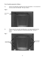
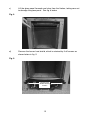
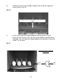
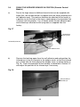
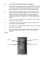
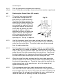
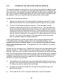
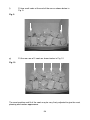
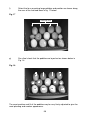
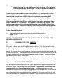
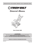
3.6
FIXING THE INFRARED SENSOR IN POSITION (Remote Control
Models)
a)
Due to the large amount of different fascia’s that can be supplied with
these fires, the infrared sensor is supplied from the factory attached to a
self adhesive pad. This pad can therefore be attached to the hearth in
a position to suit the form of the fret or contemporary trim assembly that
is chosen with the product. Fig. 37 below shows the self adhesive pad
and infrared eye attached to the flying lead, as supplied from the
factory.
Fig. 37
Infrared Eye
Flying Lead
Infrared Eye Sensor
Self Adhesive Pad
b)
Remove the backing paper from the self adhesive pad and position the
infrared eye in the air channels in the ashpan cover, so that the infrared
eye is flush with the front edge of the ashpan cover, as shown below in
Fig. 38. Check the operation of the handset, as detailed in Section 3.3
and adjust the position of the infrared eye if necessary.
Fig. 38
Final position of
infrared eye
33