1
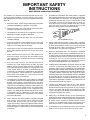
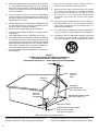
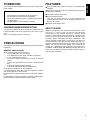
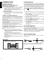
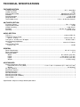
R
Model SR110 User Guide
Receiver
CAUTION
RISK OF ELECTRIC SHOCK
DO NOT OPEN
CAUTION: TO REDUCE THE RISK OF ELECTRIC SHOCK,
DO NOT REMOVE COVER (OR BACK)
NO USER-SERVICEABLE PARTS INSIDE
REFER SERVICING TO QUALIFIED SERVICE PERSONNEL
The lightning flash with arrowhead symbol, within an
equilateral triangle, is intended to alert the user to the
presence of uninsulated “dangerous voltage” within the
product’s enclosure that may be of suffi-cient magnitude
to constitute a risk of electric shock to persons.
The exclamation point within an equilateral triangle is
intended to alert the user to the presence of important
operating and maintenance (servicing) instructions in the
literature accompanying the appliance.
WARNING
TO REDUCE THE RISK OF FIRE OR ELECTRIC SHOCK,
DO NOT EXPOSE THIS APPLIANCE TO RAIN OR MOISTURE.
CAUTION: TO PREVENT ELECTRIC SHOCK, MATCH WIDE BLADE OF
PLUG TO WIDE SLOT, FULLY INSERT.
ATTENTION: POUR ÉVITER LES CHOCS ÉLECTRIQUES,
INTRODUIRE LA LAME LA PLUS LARGE DE LA FICHE DANS LA
BORNE CORRESPONDANTE DE LA PRISE ET POUSSER
JUSQU’AU FOND.
NOTE TO CATV SYSTEM INSTALLER:
This reminder is provided to call the CATV (Cable-TV) system installer’s attention to Article 820-40 of the NEC, that
provides guidelines for proper grounding and, in particular, specified that the cable ground shall be connected to the
grounding system of the building, as close to the point of cable entry as practical.
NOTE:
This equipment has been tested and found to comply
with the limits for a Class B digital device, pursuant to
Part 15 of the FCC Rules. These limits are designed
to provide reasonable protection against harmful
interference in a residential installation. This
equipment generates, uses and can radiate radio
frequency energy and, if not installed and used in
accordance with the instructions, may cause harmful
interference to radio communications. However, there
is no guarantee that interference will not occur in a
particular installation. If this equipment does cause
harmful interference to radio or television reception,
which can be determined by tuning the equipment off
and on, the user is encouraged to try to correct the
interference by one or more of the following
measures:
- Reorient or relocate the receiving antenna.
- Increase the separation between the equipment and
receiver.
- Connect the equipment into an outlet on a circuit
different from that to which the receiver is connected.
- Consult the dealer or an experienced radio/TV
technician for help.
NOTE:
Changes or modifications may cause this unit to fail
to comply with Part 15 of the FCC Rules and may
IMPORTANT SAFETY
INSTRUCTIONS
READ BEFORE OPERATING EQUIPMENT
This product was designed and manufactured to meet strict
quality and safety standards. There are, however, some installation and operation precautions which you should be particularly
aware of.
1.
Read Instructions - All the safety and operating instructions
should be read before the appliance is operated.
2.
Retain Instructions-The safety and operating instructions
should be retained for future reference.
3.
Heed Warnings-All warnings on the appliance and in the
operating instructions should be adhered to.
4.
Follow Instructions-All operating and use instructions
should be followed.
5.
Cleaning-Unplug this video product from the wall outlet
before cleaning. Do not use liquid cleaners or aerosol
cleaners. Use a damp cloth for cleaning.
6.
Attachments-Do not use attachments not recommended
by the video product manufacturer as they may cause
hazards.
7.
Water and Moisture-Do not use this video product near
water-for example, near a bath tub, wash bowl, kitchen
sink, or laundry tub, in a wet basement, or near a swimming
pool, and the like.
8.
Accessories-Do not place this video product on an
unstable cart, stand, tripod, bracket, or table. The video
product may fall, causing serious injury to a child or adult,
and serious damage to the appliance. Use only with a cart,
stand, tripod, bracket, or table recommended by the
manufacturer, or sold with the video product. Any mounting
of the appliance should follow the manufacturer’s
instructions, and should use a mounting accessory
recommended by the manufacturer.
9.
10.
Ventilation-Slots and openings in the cabinet are provided
for ventilation and to ensure reliable operation of the video
product and to protect it from overheating, and these
openings must not be blocked or covered. The openings
should never be blocked by placing the video product on a
bed, sofa, rug, or other similar surface. This video product
should never be placed near or over a radiator or heat
register. This video product should not be placed in a builtin installation such as a bookcase or rack unless proper
ventilation is provided or the manufacturer’s instructions
have been adhered to.
Power Sources-This video product should be operated
only from the type of power source indicated on the
marking label. If you are not sure of the type of power
supply to your home, consult your appliance dealer or local
power company. For video products intended to operate
from battery power, or other sources, refer to the operating
instructions.
11.
Grounding or Polarization-This video product is equipped
with a polarized alternating-current line plug (a plug having
one blade wider than the other). This plug will fit into the
power outlet only one way. This is a safety feature. If you
are unable to insert the plug fully into the outlet, try
reversing the plug. If the plug should still fail to fit, contact
your electrician to replace your obsolete outlet. Do not
defeat the safety purpose of the polarized plug.
AC POLARIZED PLUG
12.
Power-Cord Protection-Power-supply cords should be
routed so that they are not likely to be walked on or pinched
by items placed upon or against them, paying particular
attention to cords at plugs, convenience receptacles, and
the point where they exit from the appliance.
13.
Protective Attachment Plug - The appliance is equipped
with an attachment plug having overload protection. This is
a safety feature. See Instruction Manual for replacement or
resetting of protective device. If replacement of the plug is
required, be sure the service technician has used a
replacement plug specified by the manufacturer that has
the same overload protection as the original plug.
14.
Outdoor Antenna Grounding-If an outside antenna or cable
system is connected to the video product, be sure the
antenna or cable system is grounded so as to provide some
protection against voltage surges and built up static charges.
Section 810 of the National Electrical Code, ANSI/NFPA No.
70-1984, provides information with respect to proper
grounding of the mast and supporting structure, grounding
of the lead-in wire to an antenna discharge unit, size of
grounding conductors, location of antenna-discharge unit,
connection to grounding electrodes, and requirements for
the grounding electrode. See Figure 1.
15.
Lightning-For added protection for this video product
receiver during a lightning storm, or when it is left unattended and unused for long periods of time, unplug it
from the wall outlet and disconnect the antenna or cable
system. This will prevent damage to the video product due
to lightning and power-line surges.
16.
Power Lines-An outside antenna system should not be
located in the vicinity of overhead power lines or other electric
light or power circuits, or where it can fall into such power lines
or circuits. When installing an outside antenna system,
extreme care should be taken to keep from touching such
power lines or circuits as contact with them might be fatal.
17.
Overloading-Do not overload wall outlets and extension
cords as this can result in a risk of fire or electric shock.
i
18.
Object and Liquid Entry-Never push objects of any kind into
this video product through openings as they may touch
dangerous voltage points or short-out parts that could
result in a fire or electric shock. Never spill liquid of any kind
on the video product.
19.
Servicing-Do not attempt to service this video product
yourself as opening or removing covers may expose you to
dangerous voltage or other hazards. Refer all servicing to
qualified service personnel.
20.
Damage Requiring Service-Unplug this video product from
the wall outlet and refer servicing to qualified service
personnel under the following conditions:
a.
When the power-supply cord or plug is damaged.
b.
If liquid has been spilled, or objects have fallen into the
video product.
c.
If the video product has been exposed to rain or water.
d.
If the video product does not operate normally by following
the operating instructions. Adjust only those controls that
are covered by the operating instructions as an improper
adjustment of other controls may result in damage and will
often require extensive work by a qualified technician to
restore the video product to its normal operation.
e.
If the video product has been dropped or the cabinet has
been damaged.
f.
When the video product exhibits a distinct change in
performance-this indicates a need for service.
21.
Replacement Parts-When replacement parts are required,
be sure the service technician has used replacement parts
specified by the manufacturer or have the same
characteristics as the original part. Unauthorized
substitutions may result in fire, electric shock or other
hazards.
22.
Safety Check-Upon completion of any service or repairs to
this video product, ask the service technician to perform
safety checks to determine that the video product is in
proper operating condition.
23.
Carts and Stands-The appliance should be used only with
a cart or stand that is recommended by the manufacturer.
24.
An appliance and cart combination should be moved with
care. Quick stops, excessive force, and uneven surfaces
may cause the appliance and cart combination to overturn.
FIGURE 1
EXAMPLE OF ANTENNA GROUNDING ACCORDING TO
NATIONAL ELECTRICAL CODE INSTRUCTIONS
CONTAINED IN ARTICLE 810 - “RADIO AND TELEVISION EQUIPMENT”
ANTENNA
LEAD IN
WIRE
GROUND
CLAMP
ANTENNA
DISCHARGE UNIT
(NEC SECTION 810-20)
ELECTRIC
SERVICE
EQUIPMENT
GROUNDING CONDUCTORS
(NEC SECTION 810-21)
GROUND CLAMPS
POWER SERVICE GROUNDING
ELECTRODE SYSTEM
(NEC ART 250, PART H)
NEC - NATIONAL ELECTRICAL CODE
This Class B digital apparatus meets all requirements of the
Canadian Interference - Cansing Equipment Regulations.
ii
Cet appareil numérique de la Classe B respecte toutes les
exigences du Règlement sur le matériel brouilleur du Canada.
1
2
STANDBY
AUX
FM/AM
3
DISPLAY
MUTE
4
5
OPEN
1
CD
CDR
MD
SR110
2
6
3
5
F/P
RANDOM
7
NEWS/TA
VOLUME
REPEAT
7
4
6
STANDBY
8
9
10
11
12 13 14
DISPLAY
MUTE
8
10
VOLUME
AMP
BAND
+
9
11
12
13
MUTE
16
OPEN
CDR
DISPLAY
WOW
ENTER
TIMER
14
WOW
TIMER
PHONES
15
SLEEP
MEMO
TUNER
17
19
18
20
15
16
17
SYSTEM REMOTE CONTROLLER
RC110SR
MODEL NO. SR110
ANTENNA FM (75Ω)
CD
AUX
AM
IN
CDR
OUT
IN
MD OUT
SPEAKER
SYSTEM
REMOTE CONTROL
LEFT
IN
SELECTOR
SYSTEM
INT.
OUT
RIGHT
A
LEFT
RIGHT
B
C
D
E
F
G
H
I
iii
FEATURES
This section must be read before any connection is made to the
mains supply.
Easy operation with remote control bus in SYSTEM mode
operation
WARNINGS
High power output of the discrete configuration possesses a
high level of reliability.
ENGLISH
FOREWORD
30-Station random preset tuner
Do not expose the equipment to rain or moisture.
Do not remove the cover from the equipment.
Do not push anything inside the equipment through the
ventilation holes.
Do not handle the mains lead with wet hands.
System operation switch
This unit can be operated as a system component in
combination with the CD, CD-R and MD players from the
Marantz AV system.
Program Timer/Sleep Timer
EQUIPMENT MAINS WORKING SETTING
Your Marantz product has been prepared to comply with the
household power and safety requirements that exist in your
area.
SR110 can be powered by 120 V AC only.
PRECAUTIONS
The following precautions should be taken when operating the
equipment.
GENERAL PRECAUTIONS
When siting the equipment ensure that:
— the ventilation holes are not covered;
— air is allowed to circulate freely around the equipment
— it is on a vibration free-surface;
— it will not be exposed to interference from an external
source;
— it will not be exposed to excessive heat, cold, moisture or
dust;
— it will not be exposed to direct sunlight;
— it will not be exposed to electrostatic discharges
Never place heavy objects on the equipment.
If a foreign body or water does enter the equipment, contact
your nearest dealer or service centre.
Do not pull out the plug by pulling on the mains lead, hold the
plug.
It is advisable when leaving the house, or during a thunderstorm,
to disconnect the equipment from the mains supply.
ABOUT THE WOW
WOW is a proprietary new algorithm from SRS Labs, which
processes a stereo signal to provide extraordinary
enhancement to the listening experience. Ordinary stereo
present a rather limited spatial presentation, and often lackluster bass (low frequency) performance. Any sound system
including smaller multimedia speakers, headphones, mini
stereos, portable “boom boxes” or televisions can deliver an
audio performance with dramatically improved image size,
dynamics and immersion when playing a signal processed with
WOW. The procession of the spatial cues surrounds the
listener with a holographic representation of the performance.
In addition, TruBass builds upon WOW by providing bass that is
deep, rich and controlled, through means that don’t require a
large speaker or cabinet.
1
ENGLISH
CONTROL BUTTON ON THE
REMOTE CONTROL UNIT
q Power switch
Press this switch to turn the power of the unit ON. If components
of Marantz AV system are connected through the REMOTE
CONTROL bus, this will turn these components ON. Press this
switch again to turn the unit OFF, and the unit enters standby
mode.
w Function buttons
There are FM/AM, CD, CD-R, MD and AUX buttons. These
buttons are used to select the source to be played or recorded.
To switch the input selector of the receiver, press the button.
Function button control
on the remote
FM/AM
CD
CD-R
MD
AUX
Source to be played
FM or AM
CD player (CD110)
CD Recorder
MD deck
AUX (TV game, etc.)
e Numeric (ten keypad) button
These buttons are used to select the preset memory when FM/
AM function is selected.
These buttons are used to enter the track or program number
when CD or CD-R function is selected.
r NEWS/TA / REPEAT button
This button is used to repeat the disc, tracks or programme when
CD, CD-R or MD function is selected.
t F/P / RANDOM button
This button is used to display the frequency or preset channel.
This button is used to random play when CD, CD-R or MD function
is selected.
yu – VOLUME + button
These buttons are used to change the volume for listening.
Press the + button to increase and the – button to decrease the
volume.
i 3 (Play) button
This button is unavailable when FM/AM function is selected.
This button is used to play the source disc when CD, CD-R or MD
function is selected.
o ¢ button
This button is used to increase the number on the tuner preset
memory or advance to next track on CD, CD-R or MD.
!0 4 button
This button is used to decrease the number on the tuner preset
memory or return to previous tracks on CD, CD-R or MD.
!1 7 (Stop) button
This button is unavailable when FM/AM function is selected.
This button is used to stop the source disc playing/recording when
CD, CD-R or MD function is selected.
2
!2 ¡ button
This button is used to increase the frequency when FM/AM
function is selected.
This button is used to search forward when CD, CD-R or MD
function is selected.
!3 1 button
This button is used to decrease the frequency when FM/AM
function is selected.
This button is used to search backward when CD, CD-R or MD
function is selected.
!4 8 (Pause) button
This button is unavailable when FM/AM function is selected.
This button is used to interrupt the source disc playing/recording
when CD, CD-R or MD function is selected.
!5 WOW button
This button is used to change the WOW function level.
Each press of this button change the WOW function level following
order.
OFF → LOW → HIGH → OFF
Note:
When this button is pressed, the sound of speakers is muted
momentary. This is not malfunction.
!6 MUTE button
This button is used to mute the sound from the speakers. When
this button is pressed, the speakers’ sound level is muted and
“MUTE” appears on the display. Pressing this button again cancels
the muting function, and it can also be cancelled by pressing one
of the function buttons.
!7 SLEEP timer button
This button is used to set the sleep timer. Each press of this
button change the sleep time following order.
10 → 20 → 30 → 60 → 90 → OFF (original display)
The display is dimmed when the sleep timer is set. The setting
time passes, the power is turned off.
!8 TIMER program button
This button is used to activate the timer program.
!9 DISPLAY button
This button is used to change the display information (source,
and present time) or brightness.
Note:
A present time can be displayed when the FM/AM function is
set with function button. A present time can be also
displayed for 10 seconds in standby mode when the FM/AM
function is set with function button.
@0 ENTER button
This button is used to decide for the receiver’s JOG control.
ENGLISH
OPERATION OF REMOTE CONTROL UNIT
1. REMOTE CONTROL
The distance between the transmitter of the remote control unit
and the IR SENSOR of the SR110 should be less than about 5
meters. If the transmitter is pointed to a direction other than the
IR SENSOR or if there is an obstacle between them, remote
control may not be possible.
A
pp
ro
x
5
m
et
er
s
Remote-controllable range
°
0
6
2. LOADING BATTERIES
The life of the batteries used with the remote control unit is
about 6 months with normal use. Also be sure to replace
batteries earlier when you notice that they are getting weak.
1.
Remove the back cover.
2.
Insert the new batteries (AA type) with correct (+) and (–)
polarity.
3.
Close until it clicks.
3
ENGLISH
CONNECTORS AND CONTROLS
ON THE MAIN UNIT
A Terminal for FM antenna, 75 ohms
For connecting an external FM antenna with a circular plug, or for
connecting a cable network.
Terminals for AM antenna and
Grounding
To connect the supplied AM loop antenna, use the terminals
marked “AM” and “GND”.
In areas where the AM loop antenna gives unsatisfactory results,
it is recommended that the receiver be connected to an outdoor
antenna. Use the terminal marked ‘AM’ for this. A grounding lead
can be connected to the terminal marked ‘GND’ to further reduce
interference. In this case, it must be connected together with the
supplied loop antenna.
Press to turn power ON and press again to switch to STANDBY
mode. The indicator lights GREEN when power is ON, and lights
RED when in STANDBY mode. The indicator lights AMBER when
the timer program is set during STANDBY mode.
x DISPLAY button
This button is used to change the display for information such as
clock time.
A present time can be displayed for 10 seconds in standby mode
by pressing this button.
The brightness of the display can be changed to dimmer or normal
by pressing this button.
c MUTE button
Connect to the audio output jacks of a CD player.
This button is used to mute the sound from the speakers. When
this button is pressed, the speakers’ sound level is muted and
“MUTE” appears on the display. Pressing this button again cancels
the muting function, and it can also be cancelled by pressing one
of the function buttons.
C AUX input jacks
v Door OPEN button
Connect to the audio output jacks of the TV set, DVD player, etc.
This button is used to open the door.
D CD-R input/output jacks
b Front panel door
Connect the IN jacks to the output jacks of a CD-R player, and
the OUT jacks to its input jacks.
This door be opened by pressing the door OPEN button.
B CD input jacks
E MD input/output jacks
Connect the IN jacks to the output jacks of a MD player, and the
OUT jacks to its input jacks.
F REMOTE CONTROL jacks
Connect to a component equipped with remote control jacks.
(Refer to page 3.)
G System control switch
This switch selects the system operation mode. Set to SYSTEM
position when the unit is being used in combination with a CD
(CD110). If your component is not capable of system connection,
set this switch to INT position.
H AC power cord
Plug into an AC 120V household outlet.
I SPEAKER terminals
Connect the left and right speaker leads, observing the + and –
polarity of the leads and terminals.
4
z STANDBY/power switch and
indicator
n IR lens
You can operate the unit even if the receiver door is closed. The
infrared signal from the remote control enters the unit through
this lens and infrared sensor.
Note:
Never remove this lens. If you remove this lens, the receiver
cannot receive the infrared signal from remote control when
the SR110’s door is closed.
m JOG control
The JOG control can be used in the AMP, TUNER and TIMER
modes. Details of operation are as follows:
AMP mode: Source select (Usual setting)
Balance control (AMP button is pressed twice)
Treble control (AMP button is pressed three
times)
Bass control (AMP button is pressed four times)
(When the AMP button is pressed once, volume
control mode is set for volume control knob.)
TUNER mode: Frequency scan mode (last operation is
memorised)
Preset memory mode (last operation is
memorised)
Auto, Mono selecting Mode
TIMER mode: Program and confirm timer setting
For more detail, refer to the respective page.
⁄5 PHONES jack
The JOG control can be used in the TUNER, AMP or TIMER
modes. Press to change the mode of JOG control to AMP mode.
5 seconds after the previous JOG operation is finished, the mode
of JOG control will return to AMP mode automatically. You can
also use this button to return to AMP mode immediately. The
function of JOG control in AMP mode is changed as follows (except
the volume adjust mode):
SOURCE select mode: To select input mode.
(Volume adjust mode: To adjust the volume level by turning
the volume control.)
Balance control mode: To adjust the speaker balance.
BASS control mode: Tone control (Low frequency)
TREBLE control mode: Tone control (High frequency)
The AMP mode is used for tone control (BASS/TREBLE) and to
change also source for JOG control.
For connecting a pair of stereo headphones. When the
headphones are connected to this jack, the speaker sound is
turned off.
ENGLISH
, AMP button
Note:
Door cannot be closed when headphones connected.
⁄6 Display panel
This panel shows information on the status of the unit.
⁄7 Infrared sensor
The infrared signal from the remote control enters the unit through
this sensor.
. TUNER button
Press to select FM or AM tuner when another source is selected
and select the JOG operation for TUNER selection. Use this button
to select the JOG operation for a scan of frequency or preset
memory mode. The TUNER button changes modes as below.
FREQUENCY mode: To scan tuning by frequency by JOG
control.
PRESET mode: To scan tunings in the preset memory by
JOG control.
TUNER mode: To change FM broadcasting to MONO or
STEREO.
The “MONO” indicator lights up on the
display in MONO position, the “AUTO”
indicator lights up when there is no signal
and “STEREO” lights up when a stereo
signal is received.
Please refer to page 9 for tuner operations.
⁄0 TIMER button
This button is used to program and check the timer program.
Please refer to page 11 for timer program operation.
⁄1 BAND button
This button is used to change the reception band to FM or AM.
⁄2 MEMO button
This button is used to set the preset memory of the tuner or clock
time.
Please refer to the tuner and timer operations.
⁄3 WOW button
This button is used to change the WOW function level.
Each press of this button change the WOW function level following
order.
OFF → LOW → HIGH → OFF
Note:
When this button is pressed, the sound of speakers is muted
momentary. This is not malfunction.
⁄4 VOLUME control
To increase or decrease sound level. To increase the sound level
turn clockwise, and to decrease turn counter-clockwise.
5
ENGLISH
CONNECTIONS
SYSTEM OPERATION
SYSTEM CONNECTION
FEATURES OF SYSTEM CONNECTION
Synchronized power ON/OFF
By switching the power switch q/z, you can turn the CD
player, CD Recorder and MD deck connected through the
REMOTE CONTROL bus connection ON or OFF.
You cannot turn on and off by pressing the power switch of
connected components.
Auto source selection
When the CD in the CD110 starts playing by pressing the
play button on the CD110, the SR110 receiver will change
source automatically.
The remote control system can be used to control Marantz
system components equipped with REMOTE CONTROL (Bus)
jacks and SYSTEM (Bus) jacks, such as CD110. An example
procedure for system operation is described below. Here, we
take as an example the connection of a CD player (CD110) to
this receiver (SR110) through the REMOTE CONTROL jacks.
(The numbers of controls and buttons on the main unit are
enclosed in , and those on the remote control are enclosed in
.)
1.
2.
3.
CONNECT TO SYSTEM CONNECTION
This unit is equipped with the remote control bus function.
Connecting it to Marantz AV system components equipped with
REMOTE CONTROL jacks, such as a CD player (CD110),
means that these components can be remote controlled from
this unit (SR110).
Connect the REMOTE CONTROL jacks of this unit to the
REMOTE CONTROL jacks of another component using RCAtype pin lead provided.
To operate the SR110 in the SYSTEM mode, the leads from the
other components must be connected to the SR110.
The lead from OUTPUT terminal of other component is
connected to INPUT terminal of the SR110.
Set the REMOTE CONTROL selector of this unit (SR110) to
SYSTEM position. Set the REMOTE CONTROL selector of
connected components to EXT position.
Note:
– Plug into AC outlet after all connections are finished.
– When connecting the supplied audio cable, confirm the
red plugs are connected to R jacks and the white plugs
are connected to L jacks.
We recommend you use to supplied audio cable.
– When using the supplied digital optical cable, remove the
dust cover.
– Attach the dust cover to prevent dust when removing the
digital optical cable.
– When connecting the digital optical cable, make sure it is
fully inserted.
4.
5.
6.
7.
8.
Press the power switch q/z to turn the receiver power
ON.
All the components connected to the REMOTE CONTROL
jacks are turned ON.
Press the CD button w to select CD player as a source
and set the remote control to CD mode.
Press the “5” of the numeric button e to select track
number 5 of the CD.
The CD player (CD110) starts to play the CD.
Press the VOLUME buttons yu or turn the VOLUME
control ⁄4 to adjust the listening volume.
Press the 7 !1 button to stop the CD.
Press the power switch q/z to turn the power off and into
the standby mode.
The SR110 receiver and all the components connected to it
are turned OFF.
NO SYSTEM CONNECTION
You can use connected components as a single unit by setting
the system control switch to INT position.
When you use this unit in combination with other Marantz
components for which a system connections is not possible, or
components of other brands, you can use them independently
by setting the system control switch to INT position.
NOTE OF SPEAKER CABLE
When connecting the speaker cable, you use the cable as
following figures;
IMPORTANT
– When the system connection is setup, SR110 and CD110
should be stacked as following figures.
0.6 mm -1.5 mm
SR110
STANDBY
DISPLAY
MUTE
OPEN
Never use the cable as following figures. If you use the
following cable, the speaker terminal may be damaged.
SR110
STANDBY
OPEN
CD110
CD110
x mm >1.5 mm
6
ENGLISH
AM LOOP ANTENNA
FM FEEDER ANTENNA FM EXTERNAL ANTENNA
SPEAKER SYSTEM
(L)
F-type (for U version) / IEC type (for N version)
converter plug (attached)
When using the FM antenna
attach to this apparatus
(R)
MODEL NO. SR110
ANTENNA FM (75Ω)
CD
GND
AUX
IN
AM
CDR
OUT
IN
MD
OUT
SPEAKER
SYSTEM
REMOTE CONTROL
LEFT
IN
SELECTOR
SYSTEM
INT.
OUT
RIGHT
RIGHT
ANALOG OUT REMOTE CONTROL
LEFT
COAX.– DIGITAL OUT –OPT.
LEFT
MODEL NO. CD110
IN
RIGHT OUT
REMOTE EXT. INT.
CONTROL
SELECTOR
7
ENGLISH
BASIC OPERATIONS
NORMAL PLAY
1.
2.
Press the power switch q/z to turn the power ON.
Press the optimum function button w or turn JOG control
m in the SOURCE select mode to select the source to be
played. Please refer to the next table.
Function button control
on the remote
FM/AM
CD
CDR
MD
AUX
3.
FM or AM
CD player (CD110)
CD recorder
MD deck
AUX (TV game, etc.)
Start playing the source component. Adjust the listening
volume with the VOLUME control ⁄4 or VOLUME buttons
yu.
The source selector will change players automatically in
SYSTEM mode.
The speaker balance can be changed by JOG control.
1. Press the AMP button , twice to set the mode of the JOG
control m to BALANCE mode.
“BAL” is displayed.
3.
8
The Bass and Treble frequencies can be controlled by JOG
control.
1. Press the AMP button , three or four times to set the mode
of JOG control m to TONE control mode. “TRE” or “BASS” is
displayed.
Source to be played
TO ADJUST BALANCE
2.
TO ADJUST TONE CONTROL (BASS AND TREBLE)
Turn the JOG control m to adjust the speaker balance
within approx. 5 seconds.
Turn left to increase the “L” digit and decrease the output of
the right speaker. Turn right to increase the “R” digit and
decrease the output of the left speaker.
The balance step can be changed up to 13.
To set and return the original display, press the JOG
control m.
2.
Within approx. 5 seconds, turn the JOG control m to the
left to decrease, or to the right to increase step by step.
You can both increase and decrease the tone for 5 step
To set and return the original display, press the JOG
control m.
PRESET MEMORY OPERATION
TO LISTEN TO THE TUNER
The SR110 receiver can store up to 30 stations selected in the
FM and AM bands.
The preset memory function allows frequency, receiving mode
(STEREO or MONO) and also station name to be stored in the
memory. The preset memory can be stored in two ways:
5 2, 4
1
STANDBY
3 6
DISPLAY
MUTE
OPEN
VOLUME
AMP
BAND
+
TUNER
TIMER
Manual preset memory
3, 4
MEMO
WOW
ENGLISH
TUNER OPERATION
2
TM
R
PHONES
STANDBY
DISPLAY
MUTE
OPEN
VOLUME
BAND
AMP
1.
2.
+
Press the power switch q/z to turn the power ON.
Press the TUNER button . or FM/AM button w.
“TUNER” is displayed.
TUNER
MEMO
WOW
TIMER
TM
R
PHONES
TUNER
TUNER
1.
BAND
2.
3.
4.
5.
To select the band of reception, press the BAND button ⁄1
or the FM/AM w button on the remote control.
Press the TUNER button . to set the frequency.
“FREQ” is displayed.
Turn the JOG control m clockwise to increase or counterclockwise to decrease the frequency, or press ¡ button
!2 to increase or 1 button !3 to decrease.
3.
4.
Select the desired station, referring to “TUNER
OPERATION”.
Press the MEMO button ⁄2.
The “M” indicator will blink for approx. 5 seconds.
During this period.
Select the preset number by turning the JOG control m
right for up or left for down
Press the JOG control m to decide.
The preset number can be selected by directly entering it
with the numeric buttons on the remote control.
Auto preset memory
This allows a band to be scanned automatically, a station with
good reception to be found and to be stored in the preset
memory.
4 1
STANDBY
6.
Auto scan tuning
To start the auto scan tuning, turn the JOG control m or press
and hold 1/¡ button !2/ !3 for a while continuously. Auto
scan tuning stops automatically when a broadcasting station
is tuned in, and the “TUNED” display lights up. When SR110
receives stereo broadcasting, “STEREO” display also lights
up.
Adjust the volume with the VOLUME control ⁄4 or VOLUME
buttons yu.
To receive sound in monaural, press the TUNER button .
until “TUNERMOD” is displayed. Turn the JOG control m
to display “MONO”.
2
DISPLAY
MUTE
OPEN
VOLUME
AMP
BAND
TUNER
MEMO
+
WOW
TIMER
1.
TM
R
PHONES
Press the TUNER button . or FM/AM button w.
“TUNER” is displayed.
TUNER
MEMO
TUNER
2.
Note:
- “AUTO” is set at initial. In this case, the noise is muted
when SR110 tunes a frequency of FM band which has no
broadcasting.
- Muting of the FM band is not activated when the tuner
mode is set to MONO. Please take care with the volume.
3.
4.
Press and hold down the MEMO button ⁄2 for 3 seconds or
more.
The auto preset memory operation starts.
“AutoMemo” is blinking.
When a station is received, scanning pauses for 5
seconds.
Press the JOG control m to store the received station
within 5 seconds. The scanning restarts after pressing the
JOG control m.
If the JOG control m is turned within 5 seconds, scanning
restarts and the frequency being received is not stored in
the memory.
9
5.
ENGLISH
When up to 30 stations have been preset, the auto preset
memory function automatically stops.
To stop in mid-operation, press the MEMO button ⁄2 or the
“0” button e on the remote control.
Note:
- If you operate the auto preset memory again, new
received frequency is stored into the preset memory 01
to 30. The previous preset memories are replaced to
new one.
- Preset Memory is not erased. Preset memory can be
replaced only.
RECALLING A STATION FROM THE PRESET MEMORY
1 2
STANDBY
DISPLAY
MUTE
OPEN
VOLUME
AMP
BAND
TUNER
MEMO
+
TIMER
PHONES
1.
2.
WOW
TM
R
Press TUNER button . until “Preset” is displayed.
Turn the JOG control m or press the 4 !0 or the ¢
button !1 to select a station.
For direct selection with the remote control, press numeric
button.
MEMORY BACKUP
The preset memory is stored for 1 week if the AC plug is pulled
out the AC outlet. If this period is longer than 1 week, the
memory is cleared. In this time, you need to set the preset
memory again.
10
PROGRAMME TIMER SETTING
To operate the timer program, you must set the present time.
The clock time can be set 12-hour or 24-hour system.
The following shows as an example how to set the time as 2:30
PM.
The clock displays “0:00” at initial
Operation using the main unit
You can play marantz CD player CD110, when it is connected
with remote control bus correctly.
The timer function is built into this receiver allows you to
perform the following operations:
• Setting of ON time and OFF time;
ENGLISH
PRESENT TIME SETTING
• Setting of source: The source can be selected from tuner,
CD;
• It is possible to specify the preset number 1 to 30 or track
numbers of CD;
MEMO
DISPLAY
• Setting of single operation (Once) or everyday operation
(Everyday).
1.
2.
3.
Press the DISPLAY button x until the clock time is displayed.
Press the MEMO button ⁄2.
“12/24” is displayed.
Turn the JOG control m to select “12”.
When you select “24”, the clock is set 24-hour system.
The selected system blinks.
IMPORTANT:
- The timer setting with track number specified can be
used only when the system control switch is set to
SYSTEM position except when only using the tuner.
(Refer to page 6.)
In the following procedure, each button should be pressed
within 5 seconds after pressing the previous button.
1. Press the power switch z to turn the power of the unit ON.
2. Press the TIMER button ⁄0. The display indicates “ON TM”
and the timer section blinks.
3. Set the On time.
TIMER
4.
5.
6.
7.
TIMER
Press the JOG control m to desired the system.
The hour digit blinks.
Turn the JOG control m to set the digits displayed to the
left of the colon to “2:00 PM” and press the JOG control m.
The minute digit blinks.
Turn the JOG control m to set the minutes to “30”, and
press the JOG control m.
The display blinks.
Press the JOG control m to confirm the actual clock. The
clock now starts.
Operation using the remote control
TIMER
TIMER
TIMER
1 Turn the JOG control m to adjust the hour for the On
time and press the TIMER button ⁄0.
2 Turn the JOG control m to adjust the minutes for the On
time and press the TIMER button ⁄0.
The display indicates “OFF TM” and the timer section blinks.
4. Set the Off time.
TIMER
1.
2.
3.
Press the TIMER button !8 more than 3 seconds.
“12/24” is displayed.
Press the 4 ¢ button o !0 to select “12”.
When you select “24”, the clock is set 24-hour system.
The selected system blinks.
Press the TIMER button !8 to confirm the system.
The hour digit blinks.
TIMER
TIMER
TIMER
TIMER
1 Turn the JOG control m to adjust the hour for the Off
time and press the TIMER button ⁄0.
2 Turn the JOG control m to adjust the minutes for the Off
time and press the TIMER button ⁄0.
“TimePLAY” is displayed.
5. Select a timer mode.
TIMER
4.
5.
6.
Press the 4 ¢ button o !0 to set the digits displayed
to the left of the colon to “2:00 PM” and press the TIMER
button !8.
The minute digit blinks.
Press the 4 ¢ button o !0 to set minutes to “30”, and
press the TIMER button !8.
The display blinks.
Press the TIMER button !8 to confirm the actual time. The
clock now starts.
1 Select the “TimePLAY” by turning the JOG control m.
The recording mode is unavailable for this version.
2 Press the TIMER button ⁄0.
11
6.
Select a function (Play mode)
9.
ENGLISH
10.
TIMER
TIMER
1 Turn the JOG control m to select the source (TUNER or
CD) to be played.
2 Press the TIMER button ⁄0.
3 When you select “TUNER”, turn the JOG control m to
select a preset number to be received.
When you select “CD”, turn the JOG control m to select
a track number to be played.
4 Press the TIMER button ⁄0.
Note:
If you select a track number which is not on the CD, the play
mode will start track number 1 when the timer activates.
7. Adjust the volume level
Press the TIMER button ⁄0 to decide the setting.
“TIMER” lights up in red. The setting contents are scrolled.
Press the power switch z to set the timer standby mode.
This system (SR110 and the connected components) is set
standby mode and the displays are turned off. The power
switch of SR110 lights up in amber.
Note:
Timer will not be activate when the power is turned on. Set
the standby mode to activate the timer.
You can set the timer standby mode by pressing the power
switch z while scrolling the setting contents.
PROGRAMME TIMER SETTING WITH REMOTE
CONTROL
You can set the timer setting with the power, 4, ¢ and
TIMER buttons on the remote control.
Press the 4 or ¢ button o !0 instead of turning the JOG
control m.
Other procedures are same as “Programme Timer Setting”
with SR110.
Important
- Timer play mode cannot activate when no disc is inserted
in the selected source.
NOTE OF THE TIMER FUNCTIONS
TIMER
•
•
1 Turn the JOG control m to adjust the volume level.
2 Press the TIMER button ⁄0.
8. Set Once or Daily
If the displayed time blinks, the time is incorrect. You need
to set the correct time.
SR110 can save the present time for 5 minutes if the AC
plug is pulled out the AC outlet. If the AC plug is plugged
into the AC outlet within this period (5 minutes), the present
time data is hold. You do not need to set the present time
again.
CONFIRM AND CHANGE TIMER SETTING
TIMER
1.
2.
3.
1 Turn the JOG control m to select the “Once”, when you
use this programmed event only once.
Turn the JOG control m to select the “EveryDay”, when
you use this programmed event everyday.
2 Press the TIMER button ⁄0.
Note:
If you select the “TimerOff”, this setting is cancelled.
In recording mode, the power is turned on before 1
minute at timer setting time.
12
4.
Press the power switch q/z to turn the power of the unit
ON.
Display the contents of timer setting by pressing the TIMER
button !8/⁄0.
The following programmed contents are displayed by
pressing the TIMER button !8/⁄0.
You can change the displayed content with the JOG
control m if necessary.
Press the power switch q/z again.
Important
- Timer mode is cancelled if you quit confirming halfway
through a procedure.
- Never confirm the setting after play mode starts, this will
lead to the off timer setting is cancelled and the power is
not turned off.
1.
Press the power switch q/z to turn the power of the unit
ON.
TIMER
2.
3.
4.
ENGLISH
CANCEL TIMER SETTING
Press the TIMER button ⁄0 on the front panel until “Timer
ON/OFF” is displayed.
Turn the JOG control m to select “OFF”.
Press the JOG button m.
Important
- “TIMER” indicator is extinguished when TIMER button ⁄0
is pressed for 3 seconds or more in timer playing or
recording mode.
- Never set “Once” or “Everyday” in timer playing or
recording mode. If this is set, the off timer is concealed
and the power is not turned off. You should no operate
after you confirm the setting time, the display will return
original.
SLEEP TIMER SETTING (REMOTE CONTROL ONLY)
The sleep timer function allows the unit to be in standby mode
automatically after a specified period of time.
1. While the power is ON, press the SLEEP button !7 in the
AMP mode.
2. Press the SLEEP button !7 within 5 seconds. Each press
changes the sleep timer period in the order
10 → 20 → 30 → 60 → 90 → OFF(original display).
3. When the desired period is displayed, release the SLEEP
button !7. After that, setting of the sleep timer is completed
and the count starts.
4. Press the SLEEP button !7 during the sleep timer count to
display the remaining period in standby mode. To change
the setting after the sleep timer has started the count,
display the remaining time, press the SLEEP button !7
while the remaining period is displayed, and repeat steps 3
and 4 above.
5. To cancel the sleep timer, press SLEEP button !7 until
“OFF” is displayed.
13
ENGLISH
TROUBLE SHOOTING
Should faults occur, in many cases it is not necessary to consult
your dealer or a Marantz technical service department.
On the basis of the following checks you will be able to rectify a
number of faults yourself without difficulty.
If the fault cannot be remedied after the following checks,
please consult your dealer or nearest Marantz service agent.
Sound comes from only one side.
- Check the connections of the loudspeaker which is not
working.
- Check the connections between the sound source and the
receiver.
- If using headphones, check that the plug is properly
inserted into the jack.
There is hum, buzz or howl during recording or playing.
- Are the connection plugs pushed far enough into the jacks?
You cannot hear anything, and no indicator lights up.
- The receiver is not turned ON.
- The receiver is not connected to the mains power outlet.
- The mains power outlet is not live.
You cannot hear anything, but an indicator lights up.
- Are the function buttons in the correct positions?
- Is the selected sound source functioning properly?
- Is the volume control high enough? Do not keep it in the
maximum position! The display indicates the volume level
at the moment the power is turned ON.
- Are the loudspeakers connected properly?
The recording is unsuccessful.
- Is the signal source operated correctly?
The remote control is not working.
- Check that the batteries of the remote control unit are not
exhausted.
If they are, replace them with two new batteries.
Easy operation is not working.
When the CD or other component starts playing, the receiver
changes source automatically. If this function is not working –
- Check that the system control switch on the rear panel is
set to SYSTEM position
- Check the connections of the remote control bus in
SYSTEM mode (the system control switch set to SYSTEM
position).
Please refer to CONNECTION OF REMOTE CONTROL bus
page 6.
14
TECHNICAL SPECIFICATIONS
FM TUNER SECTION
Frequency Range ......................................................................................................................... 87.5 - 108.0 MHz
Usable Sensitivity ........................................................................................................................................... 0 dBµ
Signal to Noise Ratio ........................................................................................................... Mono/Stereo 70/65 dB
Distortion ............................................................................................................................. Mono/Stereo 0.2/0.3 %
Stereo Separation ................................................................................................................................ 1 kHz 40 dB
Image Rejection ................................................................................................................................ 98 MHz 80 dB
Tuner Output Level .................................................................................................... 1 kHz, ± 40 kHz Dev 500 mV
AM TUNER SECTION
Frequency Range ............................................................................................................................. 520 - 1710 kHz
Signal to Noise Ratio ...................................................................................................................................... 40 dB
Usable Sensitivity ................................................................................................................................ Loop 500 µV
Distortion .......................................................................................................................... 400 Hz, 30 % Mod. 0.5 %
Selectivity ........................................................................................................................................ ± 18 kHz 30 dB
AUDIO SECTION
THD 10 % ...................................................................................................................................... 6 ohms 25W / Ch
Continuous Power Output
(40 Hz - 20 kHz) ...................................................................................................................... 8 ohms 21W / Ch
THD (40 Hz - 20 kHz) at 21 W output ............................................................................................. 8 ohms 0.08 %
Input Sensitivity/Impedance
Linear ................................................................................................................................... 200 mV/ 47 Kohms
Signal to Noise Ratio
Linear (1 W) .............................................................................................................................................. 80 dB
GENERAL
Power Requirement ....................................................................................................................... AC 120 V 60 Hz
Power Consumption ........................................................................................................................................ 0.7 A
Dimension (MAX)
Width ............................................................................................................................... 8-1/4 inches (210 mm)
Height ............................................................................................................................ 2-3/4 inches (71.5 mm)
Depth .......................................................................................................................... 12-3/16 inches (310 mm)
Weight .......................................................................................................................................... 9.5 lbs(4.3 Kg)
ACCESSORIES
Remote Control Unit (RC110SR) .......................................................................................................................... 1
Dimension (W x H x D) (MAX) .............................................. 2-1/2 x 7-3/4 x 1-1/8 inches (57 x 196.5 x 27 mm)
Weight ............................................................................................................................................. 0.2 lbs(90 g)
AA Type Batteries ................................................................................................................................................ 2
FM Feeder Antenna .............................................................................................................................................. 1
FM Converter Plug ................................................................................................................................................ 1
AM Loop Antenna .................................................................................................................................................. 1
Warranty Card (for USA) ....................................................................................................................................... 1
Warranty Card (for CANADA) ............................................................................................................................... 1
User’s Guide .......................................................................................................................................................... 1
Specifications subject to change without prior notice.
COUNTRY
ALGERIE
ARMENIA
AUSTRALIA
AUSTRIA
BAHREIN
BANGLADESH
BELGIUM
BULGARIA
CANADA
CHINA
CYPRUS
CZECH REPUBLIC
DENMARK
DUBAI
EGYPT
ESTONIA
F.Y.R.O.M.
FINLAND
FRANCE
GERMANY
GREECE
HEADQUARTERS EUROPE:
HONG KONG
HUNGARY
ICELAND
INDIA
IRAN
IRELAND
ISRAEL
ITALY
IVORY COAST
JAPAN
KOREA
KUWAIT
LATVIA
LEBANON
LITHUANIA
MALAYSIA
MALTA
MAURITIUS
MILITARY MARKET EUROPE
NETHERLANDS
NEW ZEALAND
NORWAY
OMAN
POLAND
PORTUGAL
PROFESSIONAL EUROPE
PROFESSIONAL U.S.A.
QATAR
REUNION
ROMANIA
RUSSIA
SAUDI ARABIA
SINGAPORE
SLOVAKIA
SLOVENIA
SOUTH AFRICA
SPAIN
SRI LANKA
SWEDEN
SWITZERLAND
SYRIA
TAHITI
TAIWAN
THAILAND
TUNESIA
TURKEY
U.K.
U.S.A.
YUGOSLAVIA
EXPORT
www.marantz.com
WOW and the
COMPANY
Azur 2000
NGYIG Ltd.
Jamo Australia Pty. Ltd.,
Huber & Prohaska GmbH
Ambassador Stores
Target
Van der Heyden Audio N.V.
Ariescommerce GmbH
Lenbrook Industries Limited
Guang Chang Audio International Co., Ltd.
Empire Hifi systems Ltd.
Audio International
Audio Nord
V.V.& SONS
Solimco
HiFi Club Estonia
T.P. KODI
Audio Nord
Marantz France
Marantz Deutschland
Adamco S.A.
Marantz Europe B.V.
Marantz Asia Ltd.
Infovox Ltd.
ID Electronics Ltd.
NOVA Audio Private
Home Co.
Marantz Ireland
Elmor Ltd.
Marantz Italy
Hifivoir
Marantz Japan Inc.
Mk Enterprises Ltd.
alAlamiah Electronics Intl.
Ace Ltd.
AZ Electronics S.A., 1,
Accapella Ltd.
Wo Kee Hong Electronics Sdn. Bhd.
Doneo Co Ltd.
SKR Electronics Ltd.
PASCO GmbH
Marantz Domestic Sales
Wildash Audio Systems
Audio Nord
Mustafa & Jawad Trading CO.
Philips Polska Sp. z.o.o.
Corel2
Marantz Professional Products
Marantz Professional Products
Almana & Partners W.W.L.
Vision +
Nova Music Entertainment
Absolute Audio
Adawlia Univ. Electr. Apl
Forward Marketing (S) Pte. Ltd.
Bis Audio s.r.o.
Bofex
Coherent Imports (PTY) Ltd.
Marantz Spain
The listening Room
Audio Nord
Sound Company AG
Hamzeh & Partners
Covecolor
Pai-Yuing Co. Ltd.
MRZ Standard Co. Ltd.
Societe EDEVIG
Türk Philips Ticaret A.S.
Marantz Hifi UK Ltd.
Marantz America Inc.
ITM Company
Marantz Domestic Sales
ADDRESS
8, Lotissement Ben Hatadi, Alger, Algerie
47 A/75 St. Lalaiants, 375000 Yerevan, Armenia
24 Lionel Road, Mt. Waverley, VIC 3149, Australia
Taborstraße 95 / Ladestraße 1, Gebäude Hangartner, A-1200 Wien, Austria
P.O. Box 237,141, Government Avenue, Manama,Bahrein
1078, Ramjoy Mohanja Lane Asadgonj, Chittagong 4000, Bangladesh
Brusselbaan 278, 9320 Erembodegem, Belgium
Makedonia Blvd. 16, 1606 Sofia, Bulgaria
633 Granite Court, Pickering, Ontario
No.38 Yushan Road, ShiQiao, Pan Yu, Guang Dong, China
P.O. Box 5604, Nicosia, Cyprus
Sokolska 41, 67902 Rajecko, OKR,Blansko, Czech Republic
Dali Allé 1, 9610 Noerager, Denmark
P.O. Box 105, Dubai, U.A.E.
9, El Attibaa St. Doki, Cairo, Egypt
Ehte 4, 90503 Haapsalu, Estonia
ul.Cedomir Kantargiev 21a, Skopje, Former Yugoslavian Republic of Macedonija
Uudenmaankatu 4-6, Helsinki SF-00120, Finland
A division of Marantz Europe B.V., P.O. Box 301, 92 156 Suresnes Cedex, France
Hakenbusch 3, 49078 Osnabrück, Germany
188, Hippocratous Street, 11471 Athens, Greece
Building SFF-2, P.O. Box 80002, 5600 JB Eindhoven, The Netherlands
Unit 1706, Metroplaza II, 223 Hing Fong Road, Kwai Fong, N.T., Kowloon, Hong Kong
Terez Krt.31, 1067 Budapest, Hungary
Armula 38, 108 Reykjavik, Iceland
8,Punam Co-op.Society 29/30 Road#5, Union Park MUMBAI 400052, India
5th floor no 878 Philips Building Enghelab ave, P.O. 11365/7844 Tehran, Iran
Clonskeagh, Dublin 14, Ireland
52 Heh Beiyar Street, Kikar Hamedina, Tel Aviv, Israel
Via Casati 23, 20052 Monza (Milano), Italy, Servizio Consumatori 1678-20026, Numero Verde
B.P. 2428, Abidjan 01, Ivory Coast
35-1 Sagami Ohno 7-Chome, Sagamihara-shi, Kanagawa 228-8505, Japan
121-210, 2F Shinhan Bldg., 247-17 Seokyo-dong, Mapo-ku, Seoul, Korea
P.O. Box 8196, Salmiah 22052, Kuwait
61, LacPlesa Str., Riga LV 1011, Latvia
P.O. Box 11 2833, Beirut, Lebanon
Ausros, Vartu G/5, Pasazo SKG., 2001 Vilnius, Lithuania
102 Jalan SS 21/35, Damansara Utama, 47400 Petaling Jaya, Selangordarul Ehsan, Malaysia
78 The Strand, Sliema SLM07, Malta
P.O. Box 685, Bell Village, Port Louis, Mauritius
PO BOX 1280, Sandhausen 69200, Germany
A division of Marantz Europe B.V., Building SFF2, P.O. Box 80002, 5600 JB Eindhoven, The Netherlands
14 Malvern Road, Mt. Albert, Auckland, New Zealand
Sandkerveien 64, Oslo 0483, Norway
P.O. Box 1918, Ruwi, Oman
Al.Jerozolimskie 195b, 02 222 Warszawa, Poland
Comércio de Electrónica Lda., Av. Luís Bívar, No 85 A, 1050 Lisboa, Portugal
Kingsbridge House, Padbury Oaks, 575-583 Bath Road, Longford, Middlesex UB7 0EH, U.K.
Distributed by: Superscope Technologies Inc., 1000 Corporate Blvd. Ste.D, Aurora, Illino
P.O. Box 49, Doha, Qatar
180 Rue du Marechal Leclerc, 97400 Saint Denis, Ile de la Reunion
5, Zagazului Str. Bl.1G,apt.18, sector 1,Bucharest, Romania
7/2, Montazhnaya Street, 107497 Moscow, Russia
P.O. Box 2154, Alkhobar 31952, Saudi Arabia
Wo Kee Hong Centre, 29 Leng Kee Road, Singapore 159099, Singapore
Nam. SNP 10, 96001 Zvolem, Slovakia
Smartinska 152, HALA V/3, 61000 Ljubljana, Slovenia
P.O. Box 1614, Alberton, 1450, South Africa
Martinez Villergas 2, Apartado 2065, Madrid 28027, Spain
Mezzanine Floor, The Landmark 385, Galle Road, Colombo - 3, Sri Lanka
Almedalsvagen 4, Gotenborg 402-23, Sweden
Postfach, 8010 Zürich, Switzerland
Hafez Ibrahim Str. No 117, Damascus Shalan, Syria
Av. Prince Hinoi, Cours de l'union sacré, P.O. Box 2334, Papeete, Tahiti
6th No 148 Sung Kiang Road, Taipei 10429, Taiwan R.O.C.
746-750 Mahachai Road, Wangburapa, Bangkok 10200, Thailand
40, Avenue du Golfe Arabe, El Menzah, 1004, Tunesia
Yukari Dudullu Organize sanayi Bolgesi, 2.Cadde no.28, 81260 Umraniye-Istanbul, Turkey
Kingsbridge House, Padbury Oaks, 575-583 Bath Road, Longford, Middlesex UB7 0EH, U.K.
440 Medinah Road, Roselle, IL 60172, U.S.A.
Omladinskih Brigada 86, 11070 Belgrade, Yugoslavia
A division of Marantz Europe BV,Building SFF2, P.O. Box 80002, 5600 JB Eindhoven, The Netherlands
symbol are trademarks of SRS Labs, Inc. WOW technology is incorporated under license from SRS Labs, Inc.
R
Printed in China
is a registered trademark.
04/2001
MITi
323W851252