1
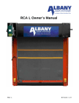
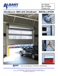
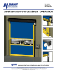
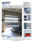
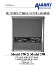
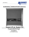
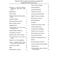
P/N:001449
Rev: 4/22/2010
Version 4.2
UltraTough M&I
OWNERS MANUAL
Doors are UltraRugged, UltraReliable, UltraAffordable.
Albany Door Systems - A Company of Albany International Corp. All Rights Reserved
1080 Maritime Drive, Port Washington, WI 53074 - 975-A Old Norcross Road, Lawrenceville, Georgia 30046
262-268-9885 www.albanydoors.com
STATEMENT OF WARRANTY
UltraTough M&I, UltraBig M&I, PosiDrive M&I High Speed Doors
EXCLUSIVE LIFETIME SBR FABRIC WARRANTY
Albany Door Systems warrants to the original owner of the door that the styrene-butadiene rubber (SBR) fabric door
panel (curtain) will be free of defects in materials and workmanship for the lifetime of the door. Door panels (curtains)
made of EPDM are warranted for a period of five (5) years. This warranty covers material failure under normal wear conditions; it does not cover labor, polyethylene terephthalate (PET) weave, windlok, roll strips, and windows after the first
twelve (12) months. Use of petroleum-based products on the door panel (curtain) will void this warranty.
ONE-YEAR WARRANTY ON MECHANICAL AND ELECTRICAL COMPONENTS
Albany Door Systems warrants to the original owner of the door that the mechanical and electrical components will be
free from defects in material and workmanship for a period of one (1) year from the date of shipment.. The warranty does
not cover fuses, heat lamp elements, bulbs, seals and straps.
Only defects brought to the attention of Albany Door Systems during the warranty period will be covered by this warranty.
Albany Door Systems will replace component parts covered by this warranty, which are found to be defective upon inspection by an Albany Door Systems representative. Installation or use of parts other than those authorized by Albany
Door Systems will void this warranty.
PARTS AND ASSEMBLIES sold separately by Albany Door Systems that fail due to defects in material or workmanship
within ninety (90) days from the date of shipment will be replaced under warranty provided installation has been carried
out in accordance with all Albany Door Systems procedures. This warranty is limited to providing a replacement part only.
This warranty does not cover freight, special charges, or any costs associated with the installation of the replacement part.
This warranty covers material failure under normal wear conditions; it does not cover damage caused by collision or other
abuse of the product. Adjustments made to the control panel or to the mechanical operation of the door without the authorization of Albany Door Systems will void this warranty. Any changes made to product configuration without the express
written approval from Albany Door Systems may null and void this warranty.
Albany Door Systems’ obligations under this warranty are limited to repairing or replacing the defective part including
labor and Albany Door Systems shall not be responsible for any other losses or damages due to the operation of any
door or parts covered by this warranty. Warranty parts will be shipped regular ground freight at the expense of Albany
Door Systems.
This warranty shall be void in its entirety if the failure of any product shall be caused by any installation, operation, or maintenance of the product which does not conform with the requirements set forth by the seller in the applicable product
manuals or is in the result of any cause other than a defect in the material or workmanship of the product.
No other oral or written representations made by Albany Door Systems or its agents are a part of this warranty unless
specifically set forth in writing by an authorized Albany Door Systems official.
THE ABOVE SET FORTH WARRANTY IS SELLER'S SOLE WARRANTY. SELLER MAKES NO OTHER WARRANTY
OF ANY KIND WHATSOEVER, EXPRESSED OR IMPLIED; AND ALL IMPLIED WARRANTIES OF MERCHANTABIL
ITY AND FITNESS FOR A PARTICULAR PURPOSE WHICH EXCEED THE AFORESTATED OBLIGATION ARE
HEREBY DISCLAIMED BY SELLER AND EXCLUDED FROM THIS AGREEMENT.
WARNING
Do not install, operate or service the product unless you have read and understand
the safety practices, warnings, installation and maintenance instructions contained
in this manual.
Albany Door Systems - A Company of Albany International Corp. All Rights Reserved
1080 Maritime Drive, Port Washington, WI 53074 - 975-A Old Norcross Road, Lawrenceville, Georgia 30045
262-268-9885 or 877-9252468
v4202010
1
Manual #001449
Version 4.2
High Speed Doors
Operation
TABLE OF CONTENTS
Introduction
3
Product Description
4
Safety Advice
5
Service & Repair
7
Troubleshooting
14
Drawings
19
Mechanical Procedures
23
Maintenance
31
ALBANY DOOR SYSTEMS CONTACT INFORMATION
Port Washington, WI
1080 Maritime Drive, Port Washington, WI 53074
Phone: 262-268-9885 Fax: 262-268-9895
Technical Support: 262-268-9885
[email protected]
www.albanydoors.com / [email protected]
Lawrenceville, GA
975 A Old Norcross Road, Lawrenceville, GA 30046
Phone: 800-252-2691 Fax: 262-268-9895
Technical Support: 262-268-9885
[email protected]
www.albanydoors.com / [email protected]
Rev. 4/9/2010
Manual #001449
2
INTRODUCTION
The contents of this manual are designed to help you operate and maintain Albany UltraTough™
high speed doors. DO NOT operate or perform maintenance on the high speed door unless
you have read through the instructions in this manual.
The safety alert symbol is used to identify safety information about hazards that can
result in personal injury. A signal word (DANGER, WARNING, or CAUTION) is
used with the safety alert symbol to indicate the likelihood and the potential severity
of injury. In addition, a hazard symbol may be used to represent the type of hazard.
DANGER indicates a hazard that, if not avoided, will
result in death or serious injury.
WARNING indicates a hazard that, if not avoided,
could result in death or serious injury.
CAUTION indicates a hazard that, if not avoided,
might result in minor or moderate injury.
CAUTION, when used without the alert symbol, indicates a situation that could result in damage to the
door.
NOTICE is used to inform you of a method, reference, or procedure that could assist with specific
operations or procedures.
Other symbols that may be used in this manual are:
Lock Out / Tag Out
3
Crushing
Fire
Manual #001449
Shock
Read Manual
Version 4.2
High Speed Doors
Operation
Product description
Function and design of this door
The model Re-Coil-Away is a vertically opening door.
Principle
The door assembly consists of left and right side frames and a header assembly. The header assembly contains the curtain and the drive system already attached. The bottom beam is already attached to the curtain. Door comes standard with a balance system and also available as an unbalanced option.
The Re-Coil-Away door rolls the curtain material directly on and off a barrel assembly. The edges of
this curtain are contained within the side frames via a patented windlok system while the curtain is
being rolled or unrolled off the barrel. These side frames guide the curtain also and provide a seal.
The bottom beam, located on the bottom of the curtain, contains a continuously monitored electrical
safety edge. Activation of this device will stop the door and cause the door to reverse to a fully open
position. The door also has a reversing photocell attached to the side frames of the door.
Control Unit
The Re-Coil-Away may be driven with the control unit ACS-50, UltraSmart or PLC with contactors.
The maximum opening speed depends on the size of the door and type of motor. See applicable
control panel manual for door operation and electrical troubleshooting guides.
Electric safety features
The Re-Coil-Away door utilizes a minimum of two safety features. This is comprised of safety photocells and electric reversing edge.
Additional Safety systems
Depending on the kind of application it may be useful to have additional sensors as safety features.
This is especially true for a door with a high volume of human traffic or with low sized doors with a
height under 10 feet (3m).
Albany Door Systems offers a variety of safety systems for high-speed doors. Some examples could
be any of the following: Light beam barriers, motion detectors, induction loops. For any other electrical requirement contact us at the factory.
Drives
The Re-Coil-Away is operated with an electrical drive. Drive side is chosen by the end-user. The
drive system could be either 1-speed or 2-speed depending on door size and customer requirements. The drive systems come in 3 different operating voltages: 208-240VAC, 440-480VAC, and
550-600VAC.
Rev. 4/9/2010
Manual #001449
4
Technical Data
Door principle:
Running direction:
Fitting position:
Drive:
Electric Power:
Maximum Horse power:
Control unit options:
Control voltage
Motor protection category:
Door frame:
Curtain:
Roll door
Vertical
External door
(also applicable as interior door)
24‟ wide x 27‟ high
48 inches per second @ 8 feet
(Depends on door size)
24 inches per second @ 8 feet
(Depends on door size)
Interior or external mounting
Electrical
240VAC, 440VAC, 575VAC
2.7 H.P.
ACS-50 / UltraSmart / PLC
24VDC
IP54 - NEMA 12
Painted Steel
SBR, EPDM
Door dimensions and fitting space
Fixing points:
See enclosed technical drawing
See fixing drawings
Application:
Maximum Sizes:
Maximum opening speed:
Maximum Closing speed:
Technical changes resulting of product maintenance are subject to
alterations
Safety advice
Area of application
The Albany Re-Coil-Away is used for the closing of door openings preferably in industrial buildings
that are highly used area of automobiles or heavy equipment.
It is a flexible exterior door with resistance to wind and weather conditions. It opens with a speed
that is especially suitable for heavy traffic throughways. It ensures a smooth transport flow and reduces collisions. The Albany Re-Coil-Away door may also be applied to interior areas.
5
Manual #001449
Version 4.2
High Speed Doors
Operation
Responsibilities of the operator
The Albany Re-Coil-Away door is designed and manufactured under consideration of safety technical specifications. This meets the highest standard of safety.
However, this safety can only be reached in operational practice if all necessary measures are met.
It is the duty of the operator of such door system to ensure all these measures and check it‟s status.
Please read the operation manual carefully and keep it in a safe place.
The operator of the door is held to ensure especially that:
Installation, first operation, inspection, servicing, repair work and dismantling are only done by
personnel that have been trained by the manufacturer.
Only to be operated by personnel that have been sufficiently assigned and authorized to operate
this door system.
The door is only used according to the determined application (see above).
The door must be only operated in a functional perfect state and especially the safety features
must be checked for function in regular intervals.
The operation manual should be kept at the site of the fitted door system in readable condition.
All safety and warning labels should not be removed from the machine and should also be kept
readable.
Do not drive through the door opening unless door is completely open.
In power loss condition the electrical drive for the door curtain can be unlocked using the disengagement chains and then the curtain hand chained upwards. When the disengage lever has
been engaged the control system has been disable.
During operation of the door do not stick your hands in the side frames. Keep hands and feet
clear of the door at all times. Stay clear of the door while it is operating.
Human traffic should be avoided within the working area of the door. Existing side doors for human traffic should be used instead.
Do not run through the door opening. Go upright and with normal pace.
Keep the working vicinity and the opening of the door in clear of obstructions. Maintain a clear
door opening at all times. Obstructions may cause accidents.
Do not climb up the door
For all kind of work on the door the main switch (main disconnect) must be set to the OFF position and locked out to prevent power from being reset.
When damage occurs to the door (mechanically or electrically) turn off operational power immediately. This is especially true if you have damage of the curtain or drive system.
USE EXTREME CAUTION when it is necessary to service the control panel or the auxiliary control box while it is energized. The door must only be operated with the correct voltage and frequency.
Use only the auxiliaries and devices authorized by the manufacturer of the door.
The STOP Button on the front of the panel is a momentary stop ONLY with the ACS-50 and UltraSmart panels. The door will only stop for that cycle; motion detectors, floor loops, or any
activating device can activate the door! To ensure that the door keeps from being activated,
use the rotary disconnect on the front of the panel.
DO NOT EVER USE PETROLUM BASED PRODUCTS ON THE CURTAIN, IF DONE THIS
VOIDS ALL WARRANTY ON THE CURTAIN MATERIAL.
Pay attention to the general safety advises mentioned under the core point SAFETY but also the
special safety advises mentioned in the other chapters of the operation manual.
Rev. 4/9/2010
Manual #001449
6
Service & Repair
Customer Service
In case of door maintenance/malfunctions or repair work, please contact the supplier or the manufacturer.
Address of Customer Services Department
1080 Maritime Drive, Port Washington, WI 53074
Phone: 262-268-9885 Fax: 262-268-9895
Technical Support: 262-268-9885
[email protected]
www.albanydoors.com / [email protected]
Inspection and maintenance
Before starting work on the door, the power must be disconnected by switching off the main power
disconnect and then locked out. Then the control box needs to be checked to verify that voltage
has been eliminated from the panel. Please observe that all used ladders, scaffoldings, or such,
correspond with the valid safety regulations.
The working area must be blocked for both vehicle and foot traffic. Lubrication oil on the floor, tools
and other material should be removed from the floor when work has been finished.
The necessary maintenance inspections, check-up and time intervals are listed in the
Inspection section.
Cleaning and maintenance of the door curtain
Do not ever use any petroleum-based products on the curtain.
Clean curtain with a citrus based cleaner or a cleaner specifically designed for cleaning SBR /
EPDM rubber materials. All cleaners are to be petroleum free and non-caustic.
Dust may be removed with a cloth. Harder dirt may be removed with water. Dirt, grease, or oil
on metal may be removed with a citrus cleaner.
7
Manual #001449
Version 4.2
Inertia Brake GFA FG220-15-60
High Speed Doors
Operation
Lock-Out Tag-out all electrical power supplied to the door before making
any electrical installations or connections. Also Lock-out Tag-out any
equipment near the installation site if that equipment may be inadvertently
operated into the area used to assemble and install the door. Failure to
properly deenergize electrical circuits and disable equipment during installation and/or maintenance could result in death or serious injury.
Rev. 4/9/2010
Manual #001449
8
Activation - Repair - Replacement
9
Manual #001449
Version 4.2
High Speed Doors
Operation
Rev. 4/9/2010
Manual #001449
10
11
Manual #001449
Version 4.2
High Speed Doors
Operation
Rev. 4/9/2010
Manual #001449
12
The picture shows all the
parts that are included in
the dampening plate repair
kit.
Situation B described in the
previous pages would be
the only time that a repair
kit would be needed.
6622T0023 Dampening plate repair kit
13
Manual #001449
Version 4.2
High Speed Doors
Operation
Troubleshooting
How to Wedge a Curtain
Why would a curtain need a wedge?
A wedge is used to correct uneven curtain build, which can be evidenced by the following symptoms:
(a)
Bottom bar tracks to either right or left thereby causing it to jam against the guide,
(b)
Bottom bar becomes out-of-level when door is in the open position,
(c)
Curtain tends to 'cone' in one direction on the barrel, as the door is rolling up.
What is a wedge?
A wedge is a piece of waste rubber (can be as large as 6" square by as much as 1/2" thickness),
which is strategically placed on the drive barrel between the curtain and the barrel. It is secured
with a self-tapping screw(s).
How to determine where to fasten a wedge.
It is normal for a curtain to 'float' slightly from side to side as the door rolls up and down. Wedging
is required only when there is a severe tracking problem such as listed above.
The placement of a wedge can be determined in several ways. For example, if the bottom bar
were tracking to the left as the door is opening, then the wedge would be fastened on the right end
of the barrel. The wedge would then make the curtain roll-up faster on the right side, thus making
the bottom bar track evenly between the guides. Should the door be tracking to the right, and then
obviously the wedge should be fastened to the left end of the barrel.
It is important to identify whether a door requires a wedge or if it has been installed out-of-level.
For instance, if a door rolls down with the bottom bar continually tracking to one side, eventually
jamming near the floor, yet the curtain does not appear to 'cone', then the door is most likely out-oflevel. To remedy the problem, it may be necessary to raise one of the end plates (which have slotted holes) to level the door.
Rev. 4/9/2010
Manual #001449
14
Removal and Re-installation of curtain in guides
1. Unbolt the hinged front guide plates of both the left and right guides. Swing the front guide
plates open and place them to the side.
1 In the event that only the upper portion is hinged, raise the curtain and bottom bar until the bottom bar front angle is just below the open hinged portion. Then, lift the curtain one end at a
time, out of the guides and set it outside the front guide plates.
2 Lower the curtain slowly and make sure that it does not catch on the guides. To re-install the
curtain, follow the above steps in reverse order. Be sure to close and bolt the front guide plates
prior to putting the door back into operation. Make sure that the guide gap is an even ½” from
top to bottom.
Removal and Re-installation of bottom bar
1. With the curtain and bottom bar supported on a flat surface, remove the bolts which secure the
bottom bar to the curtain.
2. Slip the curtain out of the bottom bar. To re-install the curtain back into the bottom bar, follow
the above steps in reverse order.
If the bottom bar is equipped with an electric reversing edge, be sure to unplug the connector when
removing the bottom bar. In addition, take extreme care not to damage the electric reversing edge
fabric. A puncture would allow moisture to penetrate it, thus causing premature failure of the reversing edge.
Repairs to rubber curtain – rips or perforations
In order to work on the ripped or perforated area, the curtain must be taken out of the guides and
lowered to the floor. Then, either work on an area supported by the floor or alternatively, a solid,
level surface provided by a heavy table, for example. Refer to Figure 31 and 32 for positioning of
the curtain prior to repairing it.
1. Using a utility knife, set it to a depth that will penetrate the rubber down to the nylon cord centre
of the curtain and cut a rectangular or square section approximately 2" wider than the sides of
the rip or perforation. Be careful not to cut the nylon cord itself (see Figure 31).
2. Using a screwdriver and pliers and starting at one corner of the cut, peel the surface from the
nylon cord centre within the perimeter of the cut.
3. Using coarse sandpaper or a wire brush, remove loose rubber particles from the nylon cord
centre. However, it is not necessary to have the fabric 100% bare.
4. Flip the curtain over to the other side of the rip or perforation and repeat Step 1 through Step 3.
5. From the 1/8" thick piece of repair rubber, cut some pieces to inlay into the prepared areas. Using a grinder with a sanding disc or a wire brush, roughen-up the inlay surfaces for bonding.
6. Mix the adhesive as per the manufacturer's instructions and apply a liberal coating to the nylon
cord fabric and the rough surfaces of the inlay rubber segments. Allow pieces to dry to the
touch (about 15 to 20 minutes) and apply a second coating. Allow to set until tacky. Place the
inlay segments into position and, using a rubber or rawhide mallet and a steel buckler, impact
the entire area of the patch repeatedly. A high degree of impact ensures proper adhesion.
Clamping is not acceptable. Allow the cement to cure thoroughly (1-1/2 to 2 hours) before moving the curtain.
7. Finally, raise the curtain to an open position, re-insert it into the guides, close and re-bolt the
guides, and resume normal operation.
15
Manual #001449
Version 4.2
High Speed Doors
Operation
Rev. 4/9/2010
Manual #001449
16
Maintenance Schedule
Due to the unique design features of your new "RE-COIL-AWAY", the need for continual maintenance normally associated with conventional door systems (i.e.: guide rollers, hinges, door track,
etc.) is virtually eliminated. The limited maintenance procedures listed below, when completed as
indicated, will assure many years of trouble-free operation.
MAINTENANCE
PROCEDURE
INITIAL
1,500 CYCLES
EVERY 25,000
CYCLES OR 3
MONTHS
EVERY 100,000 CYCLES
OR 12 MONTHS
LUBRICATE:
Flange Bearing (4)
NO
NO
Grease, 1 shot
Drive Chain
NO
OIL
OIL
ADJUSTMENTS:
(check & adjust if necessary)
17
Drive Chain Tension
YES
YES
YES
Guides, bottom bar &
header assembly for
rust or damage
YES
YES
YES
Guide Opening 1/2"
NO
YES
YES
All Fasteners (check
for tightness)
YES
YES
YES
Limit Settings
YES
YES
YES
Reversing Edge
(check for proper operation and any signs
of damage)
YES
EVERY MONTH
YES
Manual #001449
Version 4.2
High Speed Doors
Operation
Gearbox
The gear construction is maintenance-free and has lifetime lubrication. (The output shaft should be
kept rust free.)
Torque Specifications
The table below list the type of bolt, its use, and what its torque setting is
Size
5/8-11 x 2"
5/8-11 x 1-1/2"
5/8-11 x 1-1/2"
5/8-11 x 1-1/2"
1/2-13 x 2"
1/2-13 x 1-1/2"
1/2-13 x 1-1/2"
Type
Hex head bolt,
Grade 8
Hex head bolt,
Grade 8
Hex head bolt,
Grade 8
Hex head bolt,
Grade 8
Hex head bolt,
Grade 8
Hex head bolt,
Grade 8
Hex head bolt,
Grade 8
M16x2.0x40mm
T-bolt
M12x1.75x30mm
T-bolt
3/8-16 x 1-1/2"
3/8-16 x 1"
3/8-16 x 1-1/4"
5/16-18 x 1-1/2"
1/4-20 x 1-1/4"
Rev. 4/9/2010
Location
Torque (ftlb):
Drive barrel bearing to end plate
212
End plate to side frame
212
End plate to inertia brake bracket
212
End plate to spring mounting
brackets
212
Idler barrel bearing to end plate
106
Header assembly to truss/
spreader bars
Inertia brake bracket
to inertia brake
Operator to T-slot rail
(Large operator)
Operator to T-slot rail
(Small operator)
Hex head bolt,
Side frame angle to front cover
Grade 5
Socket head cap screw,
Bottom beam
grade 5
to aluminum extrusion
Button head screw,
Bottom beam angle
Grade 5
thru fabric to flat bar
Self tapping screw
Curtain to drum tube
Hex head bolt,
Break away bar on bottom beam
Grade 5
Manual #001449
106
106
59
89
31
31
31
15
8
18
M&I Re-Coil-Away Architectural Over 12’ x 12’ (Balanced)
19
Manual #001449
Version 4.2
High Speed Doors
Operation
M&I Re-Coil-Away Architectural Up To 12’ x 12’ (Balanced)
Rev. 4/9/2010
Manual #001449
20
M&I Re-Coil-Away Architectural Over 12’ x 12’ (Unbalanced)
21
Manual #001449
Version 4.2
High Speed Doors
Operation
M&I Re-Coil-Away Architectural Up to 12’ x 12’ (Unbalanced)
Rev. 4/9/2010
Manual #001449
22
M&I Re-Coil-Away XL Architectural Over 24’ x 27’
23
Manual #001449
Version 4.2
High Speed Doors
Operation
Albany Re-Coil-Away Door Mechanical Procedures
TRAVELLING WINDBAR ASSEMBLY
This is an optional accessory item which may not be applicable to model ordered.
Step 1
Step 2
Step 3
Step 4
Drive Barrel Kit Installation
Instructions for Guide-Mounted Windbar Assembly
Instructions for Jamb-Mounted Windbar Assembly
4” or 4-1/2” Windbar Tube Installation
6-5/8” or 8-5/8” Windbar Tube Installation
4” or 4-1/2” Windbar Tube Installation (cont‟d)
6-5/8” or 8-5/8” Windbar Tube Installation (cont‟d)
Travelling Windbar Part Identification
TRAVELLING WINDBAR ASSEMBLY – DRIVE BARREL
Rev. 4/9/2010
Manual #001449
24
STEP 1
Note: If your door was supplied from the factory with a Traveling Windbar, proceed directly to
Step 2.
With the door in the closed position, disconnect the power supply.
Determine dimension “A” and “B” from the chart and measure the drive barrel to the required
locations. From these locations, move to the closest center between curtain fasteners and
mark the barrel 2” from the curtain edge.
Drill a Æ 5/16” and tap 3/8 – 16 into the drive barrel at all locations.
Wrap a hold-down bar with the windbar strap (1-1/2 wraps) and pierce a hole through the strap
layers that aligns with the hole in the hold-down bar. Fasten the strap to the drive barrel with a
3/8-16NC x 5/8” LG BHCS and flat washer. Repeat this procedure with the remaining windbar
strap(s).
If you are installing a jamb-mount windbar, route the straps over the top of the curtain and down
between the curtain and the bulkhead. Check that the straps are not twisted.
If you are installing a guide-mount windbar, feed the strap between the drive barrel and the curtain. This procedure may require further closing of the door with the manual chain hoist to
loosen the curtain tension.
STEP 2
RE-COIL-AWAY WITH GUIDE-MOUNTED WINDBAR
Note: If your door was supplied from the factory with a guide-mount 6-5/8” or 8-5/8” Traveling
Windbar, proceed directly to STEP 3
If you are installing a 4” or a 4-1/2” O.D. windbar, fasten one (1) windbar track bracket to each
hole provided in the windbar tracks. Orient the windbar track bracket with the slot protruding
beyond the track edge opposite the curve. Fasten each bracket to the track using one (1) 3/816NC x 5/8” LG BHCS per bracket.
With the door in the open position, disconnect the power supply.
There is a left-hand and right-hand windbar track. Determine the appropriate location for each
track given, that the curved side is furthest from the curtain and the stop bolt holes are at the
bottom.
Determine the curtain to windbar track spacing required for your traveling windbar diameter (4”,
4-1/2”, 6-5/8” or 8-5/8” O.D.).
If you are installing a 4” or a 4-1/2” O.D. windbar, unbolt the respective guide fasteners which
align with the mounting brackets. Discard these fasteners and attach the windbar track using
the 3/8-16NC x 1-1/2” long HHCS and nuts provided.
If you are installing a 6-5/8” or an 8-5/8” O.D. windbar, position the windbar track to the guides
accordingly and weld each guide bracket to the outside of the guide back plate with two (2) 2”
long fillet welds.
25
Manual #001449
Version 4.2
High Speed Doors
Operation
TRAVELLING WINDBAR ASSEMBLY – WINDBAR TRACK
(Jamb-Mount)
STEP 2 – ALL JAMB-MOUNTED WINDBARS
Fasten one (1) windbar track bracket to each hole provided in the two (2) windbar tracks. Orient the windbar track bracket with the slot protruding beyond the track edge opposite the curve.
Fasten the bracket to the track using one (1) 3/8 – 16 NC x 5/8” long BHCS per bracket.
With the door in the open position, disconnect the power supply.
There is a left-hand and right-hand windbar track. Determine the appropriate location for each
track given, that the curved side is furthest from the curtain and the stop bolt holes are at the
bottom.
Determine the curtain to windbar track spacing required for your traveling windbar diameter
(4”, 4-1/2”, 6-5/8” or 8-5/8” O.D.).
Position the windbar track to the jamb accordingly and weld mounting bracket to the jamb or
fasten thru the slot provided.
Rev. 4/9/2010
Manual #001449
26
27
Manual #001449
Version 4.2
High Speed Doors
Operation
Rev. 4/9/2010
Manual #001449
28
TRAVELLING WINDBAR ASSEMBLY – WINDBAR TUBE INSTALLATION
STEP 3 - FOR 4” OR 4-1/2” DIAMETER WINDBARS
Determine dimensions “C” and “D” from the chart and mark the lintel (jamb mount) or the
spreader bar (guide mount) at these dimensions from the outside of the end plates.
If installing a jamb-mounted windbar, weld a lintel bracket at each mark on the lintel, 6” from the
curtain. If installing a guide-mounted windbar, temporarily center and clamp a “windbar strap
clamp” at the specified location on the lower front spreader bar to match drill the 5/16” diameter
holes.
TRAVELLING WINDBAR ASSEMBLY
STEP 3 (FOR 6-5/8” OR 8-5/8” DIAMETER WINDBARS)
OPENING WIDTH
(O.W.)
DISTANCE FROM OUTSIDE OF ENDPLATE
TO STRAP LOCATION
DIM ‘C’
DIM ‘D’
O.W. <= 120‟‟
120„‟ < O.W. <= 180‟‟
180„‟ < O.W. <= 240‟‟
240„‟ < O.W. <= 300‟‟
9 „‟
18‟‟
36‟‟
18‟‟
S/O
S/O
S/O
42‟‟
300„‟ < O.W. <= 360‟‟
27‟‟
48‟‟
360„‟ < O.W. <= 480‟‟
33‟‟
60‟‟
Determine dimensions “C” and “D” from the chart and mark the lintel (jamb-mount) or the truss
(guide-mount) at these dimensions from the outside of the end plates.
If installing a jamb-mounted windbar, weld a ratchet buckle at each mark on the lintel, 9” from
the curtain (see Detail B).
If installing a guide-mounted windbar, weld a ratchet buckle at each mark on the bottom of the
truss (see Detail A).
29
Manual #001449
Version 4.2
High Speed Doors
Operation
TRAVELLING WINDBAR ASSEMBLY
WINDBAR TUBE INSTALLATION
STEP 4 (FOR 6-5/8” OR 8-5/8” DIAMETER WINDBARS)
With the door in the closed position, disconnect the power supply.
Insert a roller wheel into each end of the windbar tube.
Lift the windbar into the bottom of the tracks. Insert one stop bolt (3/8-16NC x 3-1/2” LG HHCS)
into the holes at the bottom of each track and secure with 3/8-16NC hex nuts.
Route the windbar straps around the bottom of the windbar tube, then upward towards the lintel for
jamb-mount or spring truss for guide-mount. Check that there are no twists in the straps.
Route the loose end of each windbar strap through the slot in the spool of individual ratchets on
the lintel for jamb-mount or on the spring truss for guide-mount.
Carefully raise the door to the open position, examine the location of the windbar with respect to
the top of its tracks. If adjustments to the windbar straps are required, return the door to the closed
position to do so.
Once the adjustments are complete, trim excess strap material, leaving a minimum of three (3) full
wraps of strap on the spool of the ratchets.
Rev. 4/9/2010
Manual #001449
30
TRAVELLING WINDBAR ASSEMBLY
WINDBAR TUBE INSTALLATION
STEP 4 (FOR 4” OR 4-1/2” WINDBARS)
With the door in the closed position, disconnect the power supply.
*Note: Roller wheels may come factory-installed in windbar tube.
Insert a roller wheel into each end of the windbar tube. “Snuggly” install a set screw and nut
(nut supplied as a spacer) in both ends of the windbar tube (do not over-tighten). With set
screws in place, the roller wheels will extend and retract without separating from the windbar
tube.
Lift the windbar into the bottom of the tracks. Insert a stop bold (3/8-16NC x 3-1/2” LG HHCS)
into the hole at the bottom of each track and secure with a 3/8-16NC hex nut.
Route the windbar straps around the bottom of the windbar tube, then upward towards the lintel
(jamb-mount) or spreader bar (guide-mount). Check that there are no twists in the straps.
Route the loose end of each windbar strap between individual windbar strap clamps and temporarily fasten to the lintel bracket (jamb-mount) or spreader bar (guide-mount).
Carefully raise the door to the open position. Examine the location of the windbar with respect
to the top of its tracks. If adjustments to the windbar straps are required, return the door to the
closed position to do so.
Once adjustments are complete, secure the windbar strap and clamps to the lintel bracket
(jamb-mount) or spreader bar (guide-mount) with the fasteners provided. Trim excess strap
material leaving at least 1-1/2” of extra strap hanging below the strap clamps and fasteners.
31
Manual #001449
Version 4.2
High Speed Doors
Operation
Periodic Maintenance
Albany Door Systems high speed doors are engineered for low maintenance operation. The door
should be visually inspected daily for wear and tear, and operated to verify functions. Quarterly
maintenance should be performed to clean components and to check all safety functions and check
for mechanical and electrical integrity.
Daily Inspection
1. Inspect the door fabric for wear or damage.
2. Operate the door through several openings and closings. Verify that the door seats against the
floor and that the door fabric remains tight and does not wrinkle. Verify that the door opens fully,
slightly beyond the wall opening, and does not open too far.
If the door does not seat against the floor properly or opens to the wrong position, refer to
“Setting Door Limit Adjustments”.
If the door fabric has diagonal wrinkles the door fabric roll at the top of the door is not level
and perpendicular to the side rails. Leveling adjustments should be made as soon as possible to prevent wear or damage. Refer to the installation instructions or contact Albany
Door Systems.
3. With the door closing, place an object through the light curtain, or photo eyes, on each side of the
door. Verify that the door stops immediately.
4. If a multiple panel door is installed, check at each end of the ribs to verify that they are in place
and centered.
5. Inspect the coiled electrical wire for wear or damage.
6. Check the light curtain slots for dirt or dust accumulation and clean as necessary.
Do not stand under the door when performing the following inspection. If the bottom bar reversing switch is not functioning correctly injury can occur.
7. While the door is closing, tap the bottom of the door edge wand verify that the door stops and reverses to a fully open position.
8. See the applicable control panel or installation manual for operation details pertaining to the controls.
Rev. 4/9/2010
Manual #001449
32
Albany Door Systems - A Company of Albany International Corp. All Rights Reserved
1080 Maritime Drive, Port Washington, WI 53074 - 975-A Old Norcross Road, Lawrenceville, Georgia 30046
262-268-9885 www.albanydoors.com