1
Operating Manual
WA-1100 and WA-1600 Wavemeter
08115-M-00 (Rev. E)
Copyright © EXFO Burleigh Products Group Inc. 2002
All Rights Reserved
Wavemeter is a registered trademark of Burleigh Instruments, Inc., an EXFO company.
Table of Contents
Table of Contents....................................................................................................................................i
Assumptions .......................................................................................................................................ii
1. Introduction.......................................................................................................................................1-1
Overview.............................................................................................................................................1-1
Safety Considerations.........................................................................................................................1-2
Unpacking & Inspection......................................................................................................................1-2
Setup ..................................................................................................................................................1-3
Fiber End Cleaning .............................................................................................................................1-3
Cleaning a Fiber Optic ConnectorError! Bookmark not defined.Error! Bookmark not
defined.Error! Bookmark not defined. ...................................................................................1-4
Cleaning a Universal Connector ............................................................................................1-4
Fan Filter Cleaning .............................................................................................................................1-5
2. Front Panel Communications..........................................................................................................2-1
Front Panel Controls...........................................................................................................................2-1
Using the Front Panel Controls ..........................................................................................................2-2
Change Screens....................................................................................................................2-2
Change Parameter Values ....................................................................................................2-2
Save Parameter Values.........................................................................................................2-2
Restore Saved Parameter Values .........................................................................................2-3
Display Screens..................................................................................................................................2-3
Setup Screens ....................................................................................................................................2-5
3. Remote Communications ................................................................................................................3-1
Overview.............................................................................................................................................3-1
GPIB System Controller Settings........................................................................................................3-1
SCPI Communications Scheme .........................................................................................................3-2
SCPI Command Detail .......................................................................................................................3-6
Common Commands ............................................................................................................3-6
Measurement Instructions .....................................................................................................3-9
CALCulate Subsystem ..........................................................................................................3-11
DISPlay Subsystem ...............................................................................................................3-14
SENSe Subsystem ................................................................................................................3-16
STATus Subsystem...............................................................................................................3-19
SYSTem Subsystem .............................................................................................................3-21
TRIGger Subsystem. .............................................................................................................3-22
UNIT Subsystem ...................................................................................................................3-23
4. Theory of Operation & Calibration..................................................................................................4-1
Operating Principles ...........................................................................................................................4-1
Accuracy.............................................................................................................................................4-2
Accuracy Verification.......................................................................................................................... 4-6
Calibration .......................................................................................................................................... 4-6
Appendix A. Specifications & Labeling ............................................................................................... A-1
Dimensional Drawing ......................................................................................................................... A-2
Rack Mounting Option........................................................................................................................ A-2
Appendix B. Warranty & Service .......................................................................................................... B-1
Warranty............................................................................................................................................. B-1
Service ............................................................................................................................................... B-1
Appendix C. Error & Status Messages ................................................................................................ C-1
Error Messages.................................................................................................................................. C-2
Status Messages................................................................................................................................ C-3
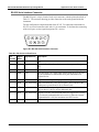
Appendix D. Rear Panel Controls ........................................................................................................ D-1
GPIB Port ........................................................................................................................................... D-1
RS-232 Serial Interface Connector .................................................................................................... D-2
Signal Monitor Connector................................................................................................................... D-3
Declaration of Conformity
Assumptions
This Operating Manual provides information for individuals who use the WA-1100 and
WA-1600.
Unless specifically stated, the information in this manual applies to both the WA-1100
and WA-1600.
This manual assumes familiarity with communication software and hardware interfaces
with an IBM, or compatible, personal computer.
WA-1100/WA-1600 Wavemeter Operating Manual
1 Introduction
1. Introduction
This section provides general information on the WA-1100/1600 and information on
unpacking and setting up the instrument.
Overview
WA-1100 and WA-1600 Wavemeter systems are instruments designed for simple,
automatic and accurate wavelength measurement of continuous wave (CW) laser
sources. Wavemeter systems count interference fringes produced by the input laser
radiation in a scanning Michelson interferometer and simultaneously count fringes from
a built-in reference laser. The ratio of the fringe counts of the input laser and the
reference laser provides the wavelength of the input laser.
The accuracy of the measured wavelength is dependent on the knowledge of the
reference laser wavelength. The WA-1100 uses a multi-mode HeNe reference laser with
an absolute wavelength accurate to within ± 500 MHz or ±1 part per million. The WA1600 uses a stabilized single frequency HeNe laser that is calibrated to an accuracy better
than ± 50 MHz relative to the Ne20 atomic line center. This corresponds to a reference
accuracy of ± 0.1 parts per million. Refer to Appendix A for complete specifications.
The WA-1100 and WA-1600 contain a rigid monolithic interferometer made from a
single piece of aluminum and housed in a compact and rugged package. This design
permits these instruments to be less susceptible to misalignment, more robust, faster and
less expensive than the previous generation of WA-1100/1600 and competitive
instruments.
Both the WA-1100 and WA-1600 products have microprocessor based electronics that
allow accurate counting and analysis of interference fringes. The microprocessor
computation automatically corrects for the refractive index of air, using data from builtin temperature and pressure sensors and converts the resulting measurement to units of
nm, cm-1 or GHz. The microprocessor also makes it possible for the instrument to
calculate and display the deviation between the measured wavelength and starting point,
or compute the average of up to 128 measurements. Refer to Section 4 for additional
information on the theory of operation.
Introduce laser light into the instrument by attaching your fiber optic cable to the fiber
optic connector on the front of the Instrument. The standard connector is FC/PC. An
FC/APC connector is available as an option at the time of order.
The ifront panel has controls to review data and review and change parameter values.
Refer to Section 2 for information on the controls and display and setup screens.
The instrument has a built-in bi-directional RS-232 interface and a GPIB interface for
transmitting data and remotely controlling the instrument. Refer to Section 3 for
information on these interfaces and the SCPI communication scheme.
08115-M-00 Rev E
1-1
WA-1100/WA-1600 Wavemeter Operating Manual
1 Introduction
The Monitor port on the back of the instrument provides access to the interferometer
fringe signals and timing signals that govern the wavelength measurement. Refer to
Appendix D for further information.
Safety Considerations
This product has been designed, manufactured and tested in accordance with EC
Standard EN61010-1, Safety Requirements for Electronic Measuring Apparatus, and has
been supplied in a safe condition. Make sure that you follow the recommendations in this
section to ensure safe operation of your instrument and to maintain the product in a safe
condition.
Laser Classification: This product is classified FDA Laser Class I (IEC Laser Class 1)
laser.
WARNING
THIS EQUIPMENT MUST BE USED AS SPECIFIED OR THE
PROTECTION PROVIDED BY THE EQUIPMENT MAY BE
COMPROMISED. YOU MUST USE THIS PRODUCT IN A NORMAL
MODE AND SHOULD NOT DEVIATE FROM THE WRITTEN
INSTRUCTIONS PROVIDED.
WARNING
THERE ARE NO OPERATOR SERVICEABLE PARTS INSIDE.
REFER SERVICING TO QUALIFIED PERSONNEL. TO PREVENT
ELECTRICAL SHOCK, DO NOT OPEN OR REMOVE COVERS.
WARNING
TO PREVENT ELECTRICAL SHOCK, TURN OFF THE POWER TO
THE INSTRUMENT BEFORE CLEANING. USE A DRY OR
SLIGHTLY DAMPENED (WITH WATER) CLOTH TO CLEAN THE
EXTERNAL PARTS. DO NOT ATTEMPT TO CLEAN ANYTHING
INSIDE THE MACHINE.
WARNING
THIS IS A SAFETY CLASS 1 PRODUCT . PLUG THE MAIN
POWER CORD INTO A SOCKET OUTLET PROVIDED WITH A
PROTECTIVE EARTH CONTACT. ALWAYS USE A THREEPRONG AC POWER CORD WITH THIS EQUIPMENT. FAILURE
TO ENSURE ADEQUATE GROUNDING MAY CAUSE
INSTRUMENT DAMAGE.
Unpacking & Inspection
The WA-1100 and WA-1600 are packed in a carton designed to give maximum
protection during shipment. If the outside of the shipping carton is damaged, notify your
shipping department immediately. Your shipping department may want to notify the
carrier.
1-2
08115-M-00 Rev E
WA-1100/WA-1600 Wavemeter Operating Manual
1 Introduction
If the external shipping carton is not damaged, carefully remove and identify all of the
components listed below. Contact EXFO or your local representative if any of the
components are missing. We recommend you save the shipping carton for future storage
or transportation.
WA-1100 and WA-1600 systems include the following components:
§
§
§
Wavemeter unit
Power cord
Operating manual
Setup
Setting up the WA-1100/1600 is a very simple operation as described in the procedure
below.
CAUTION
1.
Place the instrument on a firm horizontal surface.
2.
Attach the AC line cord. The instrument uses a universal power supply that works
with any line voltage 90-260 VAC, 50/60 Hz.
3.
Turn on the Power Switch. The system’s self-test takes approximately 30 seconds.
For WA-1600 models, the display indicates Laser Warm-up and the elapsed time, in
minutes, since the instrument was turned on. This message is displayed until the
reference laser inside the WA-1600 is stabilized. Typical laser warm-up time is
approximately 6 minutes (WA-1600 only).
4.
Ensure all fiber optic connectors are clean and dry (see below). Then connect your
fiber optic cable to the fiber optic connector on the instrument front panel. Make
sure the fiber end does not rub against any surface and do not overtighten.
Use care in handling fiber optic connectors. Always clean the fiber end
prior to insertion into the connector for optimum performance and to avoid
power measurement errors.
Fiber End Cleaning
To make good optical measurements, it is extremely important to clean the fiber optic
connector before each connection. Dirt on the connector can degrade the reliability of the
measurement and cause permanent damage to the connector resulting in an expensive
repair.
Modern fiber optic connectors rely on a glass-to-glass contact to reduce Fresnel
reflections at the connector interface. A dirty or damaged connector on the cable can
damage the input connector on the front panel. Always use a good quality cable
08115-M-00 Rev E
1-3
WA-1100/WA-1600 Wavemeter Operating Manual
1 Introduction
connector. If there is any question of the surface quality on the tip of the cable connector,
inspect it under a microscope for scratches or debris. Your instrument may use a Fiber
Optic Connector or a Universal Connector. Follow the appropriate procedure below.
Some general recommendations:
§
§
§
Never use a metal or other hard object for cleaning that would scrape the connector.
Do not apply index matching gel or oils.
Always keep connectors covered for protection when not in use.
Cleaning a Fiber Optic ConnectorError! Bookmark not defined.Error! Bookmark not
defined.Error! Bookmark not defined.
To clean the end of the connector on the fiber optic cable,
1.
Gently wipe the tip with a lint-free swab or lens paper dipped in isopropyl alcohol.
2.
Dry it by wiping gently with a clean dry lint-free lens paper.
3.
As soon as the connector is dry, insert it in the panel or cover it for later use.
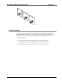
Cleaning a Universal Connector
NOTE
Refer to the illustration below.
To clean the end of the Universal Connector,
NOTE
1.
Unscrew the fiber from the Instrument and put a protective cap on it.
2.
Close the Universal protective fiber cap.
3.
Gently push in the universal connector and rotate it counter-clockwise ¼ turn.
4.
Pull out the fiber optic adapter.
5.
Gently wipe the tip with a lint-free swab or lens paper dipped in isopropyl alcohol.
6.
Dry it by wiping gently with a clean dry lint-free lens paper.
7.
As soon as the connector is dry, insert it in the WA-1100 or WA-1600 front panel or
cover it for later use.
The fiber optic adapter is keyed. Insert the adapter in the same position that you
removed it.
8.
1-4
Rotate the universal connector ¼ turn to lock it in.
08115-M-00 Rev E
WA-1100/WA-1600 Wavemeter Operating Manual
1 Introduction
Fan Filter Cleaning
The fan on the rear panel of the WA-1100/1600 provides important ventilation to
components inside the chassis. A filter covers the fan opening to keep out dust. This
filter should be cleaned periodically, especially if it becomes noticeably dirty.
To clean the dust filter,
08115-M-00 Rev E
1.
Pry off the plastic grill covering the filter with a small screwdriver.
2.
Use a small brush, plus soap and water if necessary to clean the filter.
3.
When the filter is dry, reposition it and snap the grill back in place.
1-5
WA-1100/WA-1600 Wavemeter Operating Manual
1-6
1 Introduction
08115-M-00 Rev E
WA-1100/WA-1600 Wavemeter Operating Manual
2 Front Panel Communications
2. Front Panel Communications
This section provides information on the front panel controls, describes the display and
setup screens and provides instructions on changing screen displays and parameter
values.
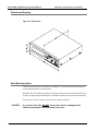
Front Panel Controls
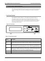
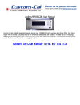
The front panel is shown in Figure 2.1. The controls are described in Table 2-1.
The display consists of an 8½ digit numerical readout and buttons for selecting
parameters that affect how the data is collected and how the information is displayed.
There are several different screens, each with different information as shown and
described later in this section.
Figure 2-1. Front Panel
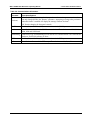
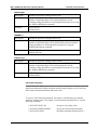
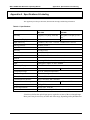
Table 2-1. Front Panel Controls
Control
Description
power
Switch turns the Instrument on and off.
LED
Indicator shows the power status. When lit, the unit is turned on, when not lit, the unit is
off.
display
Button cycles through the display screens: Main, Wavelength and Power. Display screens
contain parameters you can review and select as well as calculated or measured data for
review only. Refer to 'Display Information' later in this section for additional information.
setup
Button cycles through the setup screens: Measurement, Communications, System, Status
and Diagnostics. Setup screens contain a list of parameters for review and change. Refer
to 'Setup Information' later in this section for additional information.
select
Button "highlights" or selects parameters on the displayed screen.
↑ and ↓
Buttons change the value of the selected parameter.
08115-M-00 Rev E
2-1
WA-1100/WA-1600 Wavemeter Operating Manual
2 Front Panel Communications
Using the Front Panel Controls
Use the four display area controls to review information and make changes to the
available parameters. The headings below provide information on how to perform
various procedures using these front panel controls.
Change Screens
To change which display screen is shown, press display. The Instrument cycles between
the display screens.
To change which setup screen is shown, press setup. The instrument cycles between the
setup screens.
Change Parameter Values
Each display and setup screen contains parameters whose values you can change.
(Display screens also contain calculated or measured data.) Some parameters are located
below the line on the bottom of the display screens and other parameters are located
above the line, such as the wavelength and power units. Refer to Figures 2-2 through 2-4
for graphic illustrations of the parameters on each display screen.
To change a parameter value or status, press select to "highlight" the parameter field,
then press ↑ or ↓. The parameter's value or status changes.
NOTE
If the message "Remote Lockout" is displayed on the screen when you attempt
to change a parameter value, remote communications is enabled (On). When
enabled, you can use the front panel controls to review all parameter values, but
you cannot change any parameters except the status of the remote feature to
off.
Save Parameter Values
You may want to save parameter values that are appropriate for your application, so that
each time you power up the instrument, this information is automatically selected. Or, if
you have several instruments, you may want to set them all up the same way.
The only parameter for which you cannot save the current value is the gain. On power
up, the gain is set to the default status of "Auto".
To save parameter values, display the Configuration screen, press select to "highlight"
the Save All field, then press either ↑ or ↓. The current parameter values are saved.
2-2
08115-M-00 Rev E
WA-1100/WA-1600 Wavemeter Operating Manual
2 Front Panel Communications
Restore Saved Parameter Values
You may want to restore saved parameter values, for example, if you changed the value
for a parameter, or several parameters, to observe their effect, but then decide you want
to use the initial values.
To restore saved values, display the Setup Measurements screen, press select to
"highlight" the Restore All field. The saved values are restored.
Display Screens
The display screens provide measurement information as summarized below. Figures 2-2
through 2-5 show each display screen and Table 2-2 describes each item on these
screens.
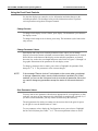
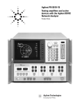
Main. Initially displays a start-up screen for approximately 30 seconds after you first
power on the unit. After a self-test and reference laser warm-up (WA-1600 only), the
screen is replaced with summary information on the current wavelength and power and
pertinent parameter values. For WA-1600s only, if the warm-up time is greater than 59
minutes, an exception occurs, which causes the wavelength to not be displayed, yet all
system functions are active. Typical warm-up time at room temperature (20°C) is less
than seven minutes
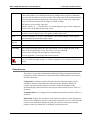
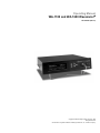
Wavelength. Displays wavelength information and two methods of calculating delta (∆)
for a comparative analysis. This screen shows the following numeric values: Current
wavelength, Start, ∆ (Current – Start), Maximum, Minimum, ∆ (Maximum – Minimum)
as well as the elapsed time and pertinent parameter values.
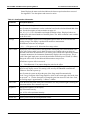
Power. Displays power information and two methods of calculating delta (∆) for a
comparative analysis. This screen shows the following numeric values: Current power,
Start, ∆ (Current – Start), Maximum, Minimum, ∆ (Maximum – Minimum) as well as the
elapsed time and pertinent parameter values.
Figure 2-2. Main Screen
Wavelength
Power
1552.5218 nm
-21.54 dBm
Error Message
Vac
08115-M-00 Rev E
Avg: 8
Gain: Auto
Poffs: Off
00:03:12
2-3
WA-1100/WA-1600 Wavemeter Operating Manual
2 Front Panel Communications
Figure 2-3. Wavelength Screen
1552.5218 nm
∆: 0.0006
Start:1552.5212
Min: 1552.5235
Max: 1552.5200
∆: 0.0035
Error Message
Vac
Avg: 8
Gain: Auto
Reset
00:03:12
Figure 2-4. Power Screen
-11.54 dBm
Max: -11.60
∆: -0.02
Start:-11.52
Min: -11.50
∆: -0.01
Error Message
Vac
Avg: 8
Gain: Auto
Reset
00:03:12
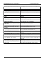
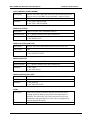
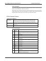
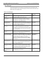
Table 2-2. Display Screen Information
Parameter
Description
Avg
Displays the number of previous measurements used to calculate the running average.
Calculation of the average wavelength and power uses the same average value. On the Main
and Wavelength screens, you can toggle the average between Off and the numeric value set
using the Measurement setup screen.
Off. Indicates averaging is not used.
Numeric value (2, 4, 8, 16, 32, 64, or 128). Change the numeric value on the Measurement
setup screen.
Gain
Displays the gain option used when measuring the wavelength and power. Change the gain
status on the Main display and Measurement setup screens.
Auto. Permits the system to adjust the gain automatically.
Fixed. Uses a fixed value, which is the current gain value at the time you pressed ↑ or ↓ on
the front panel to change the gain from "Auto" to "Fixed".
Medium
2-4
Identifies the medium in which the measurement occurs as standard air (20°C, 760 mm Hg
and 0% relative humidity) or vacuum. You can change the medium to vacuum on the Main
and Wavelength screens.
08115-M-00 Rev E
WA-1100/WA-1600 Wavemeter Operating Manual
Poffs
2 Front Panel Communications
Displays the power offset value applied to subsequent power measurements. The power
offset values enable you to obtain accurate power readings when you place an attenuator
external to the instrument. If you enter a power offset value equal to the external attenuator,
the instrument automatically displays the correct power. This is useful if the signal input
power exceeds the maximum allowed input of 10 mW (10 dBm).
Off indicates a power offset is not used.
Numeric value (1, 2, …, 20 in dB units). You cannot change the type of units. Change the
numeric value on the Measurement setup screen.
Power
The current laser power displayed in the selected units. You can change the type of units on
the Main or Power display screen. The options are dBm, mW or µW.
Reset
Restarts calculations of Current – Start and Max - Min. When actuated, it zeros elapsed
time, then displays the start and current values.
Error
Message
Indicates an error message, if any. Refer to Appendix C for messages and corrective action.
Vacuum
You can change the medium to standard air on the Main and Wavelength screens.
Wavelength
The current wavelength displayed in the selected units. You can change the units on the
Main or Wavelength display screen. The units are nm, cm-1 and GHz.
If an error has occurred, this area displays a status message.
Refer to Appendix C for messages and corrective action.
Presence indicates that an exception has occurred. Check the status screen or read the status
byte (see *STB Command on page 3-7). Refer to Appendix C for messages and corrective
action.
Setup Screens
The setup screens provide information that affects the display of measured values and
calculation of values. Each screen is summarized below and described in more detail in
the tables that follow.
Configuration. Contains parameters that affect how the instrument makes specific
calculations and how it determines the information on the instrument display, for
example, save and recall the parameter selections, change the brightness of the
instrument display, and reset the null value for power measurement. Refer to Table 2-3
for details.
Communications. Use to change remote communication parameters. Refer to Table 2-4
for details.
Information. Displays the instrument's serial number and software version information,
reference laser information, pressure, and internal temperature for review. The WA-1600
reference laser information includes the peak power, percent of peak power and the
minutes to warm up, and the WA-1100 displays just the peak power.
08115-M-00 Rev E
2-5
WA-1100/WA-1600 Wavemeter Operating Manual
2 Front Panel Communications
Status Displays the status codes that indicate the latest exceptions that have occurred.
See Appendix C for descriptions and corrective action.
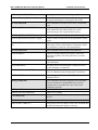
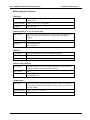
Table 2-3. Configuration Information
Parameter
Description/Options
Resolution
Identifies the wavelength resolution value.
Auto. Permits the instrument to set the resolution based on the calculated bandwidth of the
laser. See the description of auto-resolution on page 4-6.
.001, .01, 0.1, 1.0, 10.0. Selectable wavelength resolution values. Displayed values are
rounded off to the selected number of decimal places. The .0001 resolution is not available
for the WA-1100.
Average
Identifies the number of previous wavelength and power values to use to calculate the
running average. The display is updated with each new measurement.
Off. Indicates values are not averaged.
2, 4, 8, …, 128 (powers of 2). Selections for average values.
Power Offset
Displays the power offset (Poffs) value applied to subsequent power measurements. The
power offset values enable you to obtain accurate power readings when you place an
attenuator external to the instrument. If you enter a power offset value equal to the amount
of external attenuation, the instrument automatically displays the correct power. This is
useful if the signal input power exceeds the maximum allowed input of 10 mW (10 dBm).
Change the offset value on the Main and Measurement setup screens.
Off indicates a power offset is not used.
1, 2, …20 in dBm units. You cannot change the units for the offset.
Gain
Displays the gain option used when measuring the wavelength. You can change the gain
option on any display screen. This setting is not saved by the Save All command and
defaults to Auto-On at power up.
Auto. Permits the system to adjust the gain of the fringe amplifier automatically.
Fixed. Uses a fixed gain of the fringe amplifier, which is the current gain value at the time
you pressed ↑ or ↓ on the front panel to change the gain from Auto to Fixed. Once fixed,
the working range is approximately –3 dBm to + 6dBm.
Power Null
Resets the null value used in the power calculation. Use only when no light is entering the
instrument and the fiber connector cap is on.
Brightness
Changes the brightness of the display.
High. Maximum intensity.
Low. 62.5% of the maximum intensity.
Save All
Allows you to save the current parameter values.
Restore All
Allows you to restore the saved parameter values.
2-6
08115-M-00 Rev E
WA-1100/WA-1600 Wavemeter Operating Manual
2 Front Panel Communications
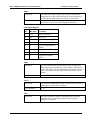
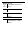
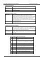
Table 2-4. Communications Information
Parameter
Description/Options
Remote
When enabled (On) you can use the front panel controls to review parameter values, but
can only change (disable) the "Remote" parameter. Attempting to change other parameters
when this feature is enabled will display the message "Remote Lockout".
(Lockout)
Off. Permits changing all front panel controls.
RS-232
Enables (On) and disables (Off) communications via the RS-232 port.
Baud
Identifies the baud rate for the RS-232 communications. The selections are: 1200, 2400,
4800, 9600 and 19200 baud.
Handshaking
Identifies the type of handshaking used for the RS-232 communications. The selections are
Hardware, Xon/Xoff (software) or None.
GPIB
Enables (On) and disables (Off) communications via the GPIB port.
Address
Identifies the address used for GPIB output. The selections are 0, 1, 2, …, 31.
08115-M-00 Rev E
2-7
WA-1100/WA-1600 Wavemeter Operating Manual
2-8
2 Front Panel Communications
08115-M-00 Rev E
WA-1100/WA-1600 Wavemeter Operating Manual
3.
3 Remote Communications
Remote Communications
This section discusses the use of remote communications to review and control the
instrument.
Overview
You can control the instrument remotely using either an RS-232 or a GPIB interface
using the SCPI communications scheme. Connections for both interfaces are provided on
the back of the instrument as shown later in this section.
You must use the instrument front panel controls to enable remote communications for
the specific type of interface. Refer to Table 2-4 in Section 2 of this manual for
information.
GPIB System Controller Settings
This section describes how to set up your GPIB system controller for proper message
termination and bus timing to communicate with the WA-1100 or WA-1600. Other
settings may also work, but these are the settings that we’ve found to work the best.
Set EOI at End of Write = Yes
This causes the system controller to assert the EOI signal during the last byte of a
message written to the instrument.
Set EOI With EOS on Write = No
The system controller should not assert the EOI signal when it writes an EOS character.
The system controller should instead assert the EOI signal when sending the last byte of
the message (which will be an EOS character anyway).
EOS Byte = 10
The instrument uses a linefeed character (10, 0x0a, or \n) to identify the end of a
message.
8-Bit EOS Compare = Yes
This causes the system controller to examine all eight bits of a received character to
determine if it is an EOS character.
Terminate Read on EOS = Yes
08115-M-00 Rev E
3-1
WA-1100/WA-1600 Wavemeter Operating Manual
3 Remote Communications
The instrument terminates all of its messages with an EOS character. It never uses the
EOS character within a message. Therefore, when the system controller receives an EOS
character from the instrument, it can assume that it has received the last character of the
message.
GPIB Bus Timing = 2000ns or 2µs
This sets the minimum time that the system controller will assert the DAV signal after
driving a byte onto the bus.
SCPI Communications Scheme
This topic provides information on the communication scheme that follows the Standard
Commands for Programmable Instruments (SCPI) Syntax and Style Guidelines.
Table 3-3 provides a summary of commands by subsystem and the information after the
table describes each command in detail.
Note: […] indicates an optional argument. {…|…|…} indicates a choice from a set of
arguments.
Table 3-3. SCPI Command Summary
Group & Command
Description
Common Commands
These commands are defined by IEEE 488.2 and control
some functions that are common to all IEEE 488.2
instruments.
*CLS
Clears all event registers and the error queue.
*ESE?
Queries the bits in the standard event status enable register.
*ESE <integer>
Sets the bits in the standard event status enable register.
*ESR?
Queries value standard event status register.
*IDN?
Queries instrument model number, serial number and
firmware version.
*OPC?
Queries the operation complete bit of the standard-event
status register.
*OPC
Sets operation complete bit of the standard event status
register.
*RCL
Restores instrument settings.
*RST
Resets instrument to default settings.
*SAV
Saves instrument settings.
*STB?
Queries the value of status byte.
3-2
08115-M-00 Rev E
WA-1100/WA-1600 Wavemeter Operating Manual
3 Remote Communications
Measurement Instructions
These commands configure and obtain measurements from
the instrument.
:CONFigure?
Queries the measurement subsystem for measurement type.
:CONFigure{:POWer | :ENVironment |
:WAVelength | :WNUM | :FREQuency}
Configures the MEASurement subsystem for power,
environment, wavelength, wavenumber or frequency.
:FETCh{:POWer | :ENVironment |
:FREQuency | :WAVelength | :WNUMber}?
Queries power, environment, wavelength, wavenumber and
frequency that have already been captured during the last
scan.
:MEASure{:POWer | :ENVironment |
:FREQuency | :WAVelength | :WNUMber }?
Queries power, environment, wavelength, wavenumber and
frequency that will be captured during the next scan.
Measure is the equivalent of ABORt; INITiate; FETch.
:READ{:POWer | :ENVironment |
:FREQuency | :WAVelength | :WNUMber}?
Queries power, environment, wavelength, wavenumber and
frequency that will be captured during the next scan.
READ is the equivalent of ABORt; INITiate; FETCh.
READ is interpreted to mean, "Initiate a new reading and
return the value when the reading is complete".
CALCulate Subsystem
These commands obtain calculated values from the
instrument. In general, calculated values are values derived
from actual measurements.
:CALCulate:DATA? {POWer | FREQuency |
WAVelength | WNUMber }
Used to set the type of data retrieved from the calculate
subsystem.
:CALCulate:DELTa[:STATe]?
Queries if DELTa is to be calculated.
:CALCulate:DELTa[:STATe] { ON | OFF }
Selects DELTa as the quantity to be calculated.
:CALCulate:DELTa:METHod?
Queries the method used for DELTa calculation (either
Current-Start or Max-Min).
:CALCulate:DELTa:METHod {STARt |
MAXMin}
Selects the method used for DELTa calculation (either
Current-Start or Max-Min).
:CALCulate:MAXimum[:STATe]?
Queries if MAXimum is to be calculated.
:CALCulate:MAXimum[:STATe] { ON | OFF Selects MAXimum as the quantity to be calculated. This is
}
the maximum value since the power-on or the last reset.
:CALCulate:MINimum[:STATE]?
Queries if MINimum is to be calculated.
:CALCulate:MINimum[:STATe] {ON | OFF}
Selects MINimum as the quantity to be calculated. This is
the minimum value since power-on or the last reset.
:CALCulate:RESet
Resets the CALCulate subsystem. This command resets the
Elapsed Time counter, sets the Min & Max values to the
Current value, and sets the Start value to the Current value.
:CALCulate:STARt[:STATe]?
Queries if STARt is to be calculated.
08115-M-00 Rev E
3-3
WA-1100/WA-1600 Wavemeter Operating Manual
3 Remote Communications
:CALCulate:STARt[:STATe] {ON | OFF}
Selects STARt as the quantity to be calculated. This is the
first good reading after power-on or last reset.
:CALCulate:TIMe[:ELAPsed]?
Returns the time since last power on or reset.
DISPlay Subsystem
These commands change the state of the instrument's front
panel.
:DISPlay:DIALog?
Queries the current display screen on the front of the
instrument.
:DISPlay:DIALog {MAIN | WAVelength |
POWer}
Selects the current display screen on the front of the
instrument.
:DISPlay:RESolution?
Queries the display resolution.
:DISPlay:RESolution {AUTO | .0001 | .001 |
.01 | .1 | 1.0 | 10.0}
Selects the display resolution. The .0001 resolution is not
available on the model WA-1100.
:DISPlay:UNITs:POWer?
Queries the power units used for display.
:DISPlay:UNITs:POWer {DBM | MICRowatts Selects the power units used for display.
| MILLiwatts}
:DISPlay:UNITs:WAVelength?
Queries the wavelength units used for display.
:DISPlay:UNITs:WAVelength {NM | GHZ |
WNUMber }
Selects the wavelength units used for display.
SENSe Subsystem
These commands are used to control factors which effect
the way in which the measurements are taken.
:SENSe:AVERage?
Queries the amount of averaging that is used in the
instrument.
:SENSe:AVERage {OFF | 2 | 4 | 8 | ... | 128}
Sets the amount of averaging that is used in the instrument.
:SENSe:MEDium?
Queries the type of medium in which the measurements are
being made.
:SENSe:MEDium {AIR | VACuum}
Selects the type of medium in which the measurements are
being made.
:SENSe:POWeroffset?
Queries the power offset for the measurements in dBm.
:SENSe:POWeroffset {OFF | 1 | ... | 20}
Selects the power offset for the measurements in dBm.
:SENSe:GAIN?
Queries the gain of the instrument’s fringe amplifier.
3-4
08115-M-00 Rev E
WA-1100/WA-1600 Wavemeter Operating Manual
3 Remote Communications
SENSe:GAIN {AUTO | FIXed}
Sets the gain of the instrument’s fringe amplifier.
:SENSe:REFerence[:PARameters]?
Returns information on the reference laser such as power
(% of peak, and minutes to warm-up for WA-1600).
STATus Subsystem
These commands are used to retrieve SCPI or instrument
status.
:STATus:QUEStionable:CONDition?
This command queries the SCPI Questionable register,
which contains bits that indicate that one or more
measurement types are of questionable accuracy.
:STATus:QUEStionable:ENABle?
This command queries the Questionable Enable register.
:STATus:QUEStionable:ENABle <integer>
Used to set and clear bits in the SCPI Questionable Enable
register.
:STATus:QUEStionable:HARDware:CONDiti This command queries the hardware to provide information
on?
on the status of some of the hardware components, which
may contribute to invalid or erred measurements.
SYSTem Subsystem
These commands control system-wide parameters.
:SYSTem:ERRor?
Reads error strings from the Error Queue. If the Error
Queue has any entries, the Error Queue bit is set in the
Status Byte.
:SYSTem:HELP:HEADers?
This query returns a list of all commands/queries supported
by the instrument.
:SYSTem:REMote?
This query checks if the front panel is enabled or not. If
ON, the front panel is locked out
:SYSTem:REMote {ON | OFF}
This command controls whether the front panel is enabled
or not. If in Remote mode, the front panel is locked out
:SYSTem:VERSion?
Returns the year and revision of the SCPI standard that the
instrument follows.
TRIGger Subsystem
These commands control the triggering of the instrument.
Since the instrument is fundamentally not a triggered
instrument, these commands have little effect on the
instrument's operation.
:TRIGger:ABORt
Aborts a current measurement.
:TRIGger:INITiate[:IMMediate]
Initiates a new reading.
UNIT Subsystem
This command effects the power units used by the SCPI
interface.
:UNIT:POWer?
Queries power units (dBm or watts).
:UNIT:POWer {DBM | W}
Selects power units to be dBm or watts. This command does
not affect the front panel display in any way.
08115-M-00 Rev E
3-5
WA-1100/WA-1600 Wavemeter Operating Manual
3 Remote Communications
SCPI Command Detail
This section provides detailed information for all instrument SCPI programming
commands. The commands are organized by subsystem.
Common Commands
*CLS
Description
The *CLS (clear status) command clears the event status register
and the error queue.
*ESE?
Description
Queries the bits in the event status enable register.
Query Response
Returns an integer which is the sum of all the bit values for those
bits that are set. (See Event Status Register Enable table below.)
*ESE <integer > mask from 0 to 255
Description
The *ESE (event status enable) command sets the bits in the event
status enable register and enables the corresponding events in the
event status register. For each bit that is set (equal to 1), it is
enabled in the event status register (ESR). <integer> is an integer
which is the sum of all of the bit values for those bits that are set.
Event Status Enable Register
3-6
Bit
Bit Value
Enables
7
128
Power On (PON)
6
64
Not Used
5
32
Command Error (CME)
4
16
Execution Error (EXE)
3
8
Device Dependent Error (DDE)
2
4
Query Error (QYE)
1
2
Not Used
0
1
Operation Complete (OPC)
08115-M-00 Rev E
WA-1100/WA-1600 Wavemeter Operating Manual
3 Remote Communications
*ESR?
Description
The *ESR (event status register) query returns a value which
encodes the bits in the event status register. If any bits are set in
the ESR, then the ESR summary bit will be set in the STB.
Query Response
Returns an integer which is the sum of all the bit values for those
bits that are set. (See Event Status Register table below.)
Event Status Register
Bit
Bit Value
Condition
7
128
Power On (PON)
6
64
Not Used
5
32
Command Error (CME)
4
16
Execution Error (EXE)
3
8
Device Dependent Error
(DDE)
2
4
Query Error (QYE)
1
2
Not Used
0
1
Operation Complete
(OPC)
*IDN?
Description
The *IDN (identification number) query returns a string value
which contains the instrument type, serial number, and firmware
version. The third value is the instrument serial number. The last
value is the software version and will reflect the actual version
number.
Query Response
BURLEIGH WAVEMETER, WA-1100, 1001, 1.0
*OPC?
Description
The operation complete query (*OPC?) returns a one (1) when all
pending device operations are complete.
Query Response
{0 | 1}
*OPC
Description
08115-M-00 Rev E
The *OPC (operation complete) command sets the operation
complete bit in the event status register when all pending
operations are complete.
3-7
WA-1100/WA-1600 Wavemeter Operating Manual
3 Remote Communications
*RCL
Description
The *RCL (recall) command restores instrument settings. It is the
same as using the Restore All function through the display.
*RST
Description
The *RST (reset) command returns the instrument’s settings to a
known state.
Commands affected by *RST
Command
Setting after an *RST
command
:CALCulate:DELTa[STATe]
OFF
:CALCulate:DELTa:METHo
d
STARt
:CALCulate:MAXimum[:STA
Te]
OFF
:CALCulate:MINimum
OFF
:CALCulate:STARt[:STATe]
OFF
:DISPlay:DIALog
MAIN
:DISPlay:RESolution
AUTO
:DISPlay:UNITs:POWer
DBM
:DISPlay:UNITs:WAVelength
WAVelengh
:SENSe:AVERage
OFF
:SENSe:MEDium
VACuum
:SENSe:POWeroffset
OFF
SENSe:GAIN
AUTO
:SYSTem:REMote
OFF
:UNIT:POWer
DBM
*SAV
Description
The *SAV command saves instrument settings. It is the same as
using the Save All function through the display.
*STB?
3-8
Description
The *STB (status byte) query returns the current value of the
instrument's status byte.
Query Response
Returns an integer which is the sum of all the bit values for those
bits that are set. (See the instrument Status Byte table.)
08115-M-00 Rev E
WA-1100/WA-1600 Wavemeter Operating Manual
3 Remote Communications
instrument Status Byte
Bit
Bit Value
Condition
5
32
a bit is set in the questionable register (see STATus
subsystem)
3
8
errors are in the error queue (see SYSTem subsystem)
2
4
a bit is set in the event status register
Measurement Instructions
Use the measurement instructions to return a reading to the computer. The four basic
measurement instructions are CONFigure, FETCh, READ, and MEASure. Functions for
these instructions are POWer, ENVironment, WAVelength, WNUMber, and
FREQuency.
A :FETCh will return a reading based on the last complete scan. Using :FETCh, it is
possible to get new measurements at the instrument's scan rate of up to 10 per second on
a WA-1100 and up to 1 per second on a WA-1600. However, if :FETCh queries are
made faster than the instrument's scan rate, it is possible to get the same reading twice.
Old readings are indicated by a bit in the questionable status register.
:MEASure and :READ get a new reading after the next complete scan. :MEASure and
:READ guarantee that each reading returned is a new one. However, because :MEASure
and :READ wait until after the next complete scan before returning a reading,
measurement rates will be about half the instrument's scan rate. If you want to get
multiple measurement types from a single scan (i.e. WAVelength, POWer, etc.), you
should use :READ followed by one or more :FETCh queries.
:MEASure and :READ are actually macros that execute multiple SCPI commands.
:READ is equivalent to:
:ABORt
:INITiate
:FETCh[:<function>]?
and :MEASure is equivalent to:
:ABORt
:CONFigure <function>
:READ?
For the instrument, :MEASure and :READ perform essentially the same function.
08115-M-00 Rev E
3-9
WA-1100/WA-1600 Wavemeter Operating Manual
3 Remote Communications
:CONFigure?
Description
Queries the current configuration of the measurement subsystem.
Query Response
{POWER | ENVIRONMENT | WAVELENGTH | WNUMBER |
FREQUENCY}
Example
:CONF?
:CONFigure{:POWer | :ENVironment | :WAVelength | :WNUMber | :FREQency}
Description
Configures the measurement subsystem for subsequent :FETCh?,
:MEASure?, or :READ? queries.
Examples
:CONF:WNUM
:CONF:POW
{:MEASure | :READ | :FETCh}{:POWer | :ENVironment | :WAVelength | :WNUMber | :FREQency}?
Description
Queries a reading of the given type from the measurement subsystem.
Query Response
(see below)
Examples
(see below)
Measurement Instruction Functions
:POWer?
Description
Returns a power reading in either Watts or dBm as specified by the
:UNIT:POWer function.
Query Response
A numerical value in scientific notation. (ex. -1.267E+001)
Examples
:READ:POW?
:FETC:POW?
:ENVironment?
3-10
Description
Returns the instrument's internal temperature in °C and pressure in
mmHG.
Query Response
Two numerical values with units separated by a comma. (ex. 28.5 C,
740 MMHG)
Examples
:MEAS:ENV?
:FETC:ENV?
08115-M-00 Rev E
WA-1100/WA-1600 Wavemeter Operating Manual
3 Remote Communications
:WAVelength?
Description
Returns an input laser reading in units of nm.
Query Response
A numerical value in scientific notation (ex. 1.5461108E+003). The
number of significant digits will be determined by the current
resolution setting. Resolution is set through the front panel or by using
the :DISPlay:RESolution command.
Examples
:FETC:WAV?
:READ:WAV?
:WNUMber?
Description
Returns an input laser reading in units of cm-1.
Query Response
A numerical value in scientific notation (ex.6.4646020E+003). The
number of significant digits will be determined by current resolution
setting. Resolution is set through the front panel or by using the
:DISPlay:RESolution command.
Examples
:FETC:WNUM?
:MEAS:WNUM?
:FREQuency?
Description
Returns an input laser reading in units of GHz.
Query Response
A numerical value in scientific notation (ex. 1.9367357E+005). The
number of significant digits will be determined by the current
resolution setting. Resolution is set through the front panel or by using
the :DISPlay:RESolution command.
Examples
:FETC:FREQ?
:MEAS:FREQ?
CALCulate Subsystem
Use the CALCulate subsystem to read and control the instrument's calculated values. The
instrument continuously updates minimum and maximum readings as well as deriving
deltas such as maximum-minimum and current-start.
To retrieve CALCulate subsystem data, first choose a calculate data type and then
perform a calculate query. For example, to read maximum-minimum power, issue the
following commands:
08115-M-00 Rev E
:CALC:DELT:STAT ON
(Set up to read a delta value.)
:CALC:DELT:METH MAXM
(Set up to read maximum-minimum.)
:CALC:DATA? POW
(Read the maximum-minimum power.)
3-11
WA-1100/WA-1600 Wavemeter Operating Manual
3 Remote Communications
The :DELTa, :MAXimum, and :MINimum functions are turned on and off with their
respective commands. When one of them is turned on, the others are automatically
turned off.
CALCulate Subsystem Functions
:DATA? {POWer | FREQuency | WAVelength | WNUMber}
Description
Gets a calculated value of a pre-selected data type. In order for this
function to return a result, you must first set up the CALCulate
subsystem using the :DELTa, :MAXimum, :MINimum, or :STARt
functions.
Query Response
A numerical value in scientific notation (ex. -1.62E+000). The number
of significant digits for a FREQuency, WAVelength, or WNUMber
reading will be determined by the current resolution setting.
Resolution is set through the front panel or by using the
:DISPlay:RESolution command.
Examples
:CALC:DATA? POW
:CALC:DATA? WAV
:DELTa[:STATe]?
Description
Queries the state of the :DELTa function.
Query Response
{0 | 1} Where 0 indicates OFF and 1 indicates ON.
Examples
:CALC:DELT:STAT?
:CALC:DELT?
:DELTa[:STATe] {ON | OFF}
Description
Sets the state of the :DELTa function to either ON or OFF.
*RST value
OFF
Examples
:CALC:DELT OFF
:CALC:DELT:STAT ON
:DELTa:METHod?
3-12
Description
Queries the state of the :METHod function.
Query Response
{START | MAXMIN}
Examples
:CALC:DELT:METH?
08115-M-00 Rev E
WA-1100/WA-1600 Wavemeter Operating Manual
3 Remote Communications
:DELTa:METHod {STARt | MAXMin}
Description
Sets the state of the :METHod function to either STARt (to get start current values) or MAXMin (to get maximum - minimum values).
*RST value
STARt
Examples
:CALC:DELT:METH STAR
:CALC:DELT:METH MAXM
:MAXimum[:STATe]?
Description
Queries the state of the :MAXimum function.
Query Response
{0 | 1} Where 0 indicates OFF and 1 indicates ON.
Examples
:CALC:MAX?
:CALC:MAX:STAT?
:MAXimum[:STATe] {ON | OFF}
Description
Sets the state of the :MAXimum function to either ON or OFF.
*RST value
OFF
Examples
:CALC:MAX ON
:CALC:MAX:STAT OFF
:MINimum[:STATe]?
Description
Queries the state of the :MINimum function.
Query Response
{0 | 1} Where 0 indicates OFF and 1 indicates ON.
Examples
:CALC:MIN?
:CALC:MIN:STAT?
:MINimum[:STATe] {ON | OFF}
Description
Sets the state of the :MINimum function to either ON or OFF.
*RST value
OFF
Examples
:CALC:MIN ON
:CALC:MIN:STAT OFF
:RESet
Description
Resets the minimum, maximum, and start values to the current
reading. Resets the deltas to zero, and sets the elapsed time to
00:00:00. This affects the CALCulate subsystem as well as the
instrument's front panel display. It is the same as using the Reset
function through the display.
Examples
:CALC:RES
08115-M-00 Rev E
3-13
WA-1100/WA-1600 Wavemeter Operating Manual
3 Remote Communications
:STARt[:STATe]?
Description
Queries the state of the :STARt function.
Query Response
{0 | 1} Where 0 indicates OFF and 1 indicates ON.
Examples
:CALC:STAR?
:CALC:STAR:STAT?
:STARt[:STATe] {ON | OFF}
Description
Sets the state of the :STARt function to either ON or OFF.
*RST value
OFF
Examples
:CALC:STAR ON
:CALC:STAR:STAT OFF
:TIMe[:ELAPsed]?
Description
Queries the elapsed time since the instrument was turned on or was
reset.
Query Response
A time in HH:MM:SS format.
Examples
:CALC:TIM?
:CALC:TIM:ELAP?
DISPlay Subsystem
The DISPlay subsystem is used to manipulate the instrument's front panel through the
serial or GPIB SCPI interface. These commands do not affect the readings from the SCPI
interface except for the :RESolution function.
3-14
08115-M-00 Rev E
WA-1100/WA-1600 Wavemeter Operating Manual
3 Remote Communications
DISPlay Subsystem Functions
:DIALog?
Description
Queries what display dialog is currently on the instrument's front
panel display. The return value for this function is invalid if the
instrument is on a setup dialog.
Query Response
{MAIN | WAVELENGTH | POWER}
Examples
:DISP:DIAL?
:DIALog {MAIN | WAVelength | POWer}
Description
Sets the dialog that is on the instrument's front panel display.
*RST value
MAIN
Examples
:DISP:DIAL MAIN
:DISP:DIAL POW
:RESolution?
Description
Queries the current resolution of the instrument.
Query Response
{AUTO | 0.0001 | 0.001 | 0.01 | 0.1 | 1.0 | 10.0 | 100.0}
Examples
:DISP:RES?
:RESolution {AUTO | 0.0001 | 0.001 | 0.01 | 0.1 | 1.0 | 10.0 | 100.0}
Description
Sets the resolution for wavelength, frequency, and wavenumber
readings. It is the same as using the Resolution function through the
display. The 0.0001 setting is valid only for the WA-1600 instrument.
*RST value
AUTO
Examples
:DISP:RES AUTO
:DISP:RES 0.0001
:UNITs:POWer?
Description
Queries the units being used for power values on the front panel
display.
Query Response
{DBM | MICROWATTS | MILLIWATTS}
Examples
:DISP:UNIT:POW?
08115-M-00 Rev E
3-15
WA-1100/WA-1600 Wavemeter Operating Manual
3 Remote Communications
:UNITs:POWer {DBM | MICRowatts | MILLiwatts}
Description
Sets the units being used for power values on the front panel display.
It is the same as changing the power units through the display. If the
units are set to MICRowatts or MILLiwatts, the display may switch to
MILLiwatts or MICRowatts due to the display's power auto ranging
feature.
*RST value
DBM
Examples
:DISP:UNIT:POW MICR
:DISP:UNIT:POW DBM
:UNITs:WAVelength?
Description
Queries the units being used for wavelength values on the front panel
display.
Query Response
{NM | GHZ | WNUMBER}
Examples
:DISP:UNIT:WAV?
:UNITs:WAVelength {NM | GHZ | WNUMber}
Description
Sets the units being used for wavelength values on the front panel
display. It is the same as changing the wavelength units through the
display.
*RST value
NM
Examples
:DISP:UNIT:WAV WNUM
:DISP:UNIT:WAV NM
SENSe Subsystem
The SENSe subsystem allows changes in how the instrument makes measurements and it
provides information on the reference laser.
3-16
08115-M-00 Rev E
WA-1100/WA-1600 Wavemeter Operating Manual
3 Remote Communications
SENSe Subsystem Functions
:AVERage?
Description
Queries the number of readings being averaged for wavelength and
power values.
Query Response
{OFF | 2 | 4 | 8 | 16 | 32 | 64 | 128}
Examples
:SENS:AVER?
:AVERage {OFF | 2 | 4 | 8 | 16 | 32 | 64 | 128}
Description
Sets the number of readings being averaged for wavelength and power
values. It is the same as using the Average function through the
display.
*RST value
OFF
Examples
:SENS:AVER OFF
:SENS:AVER 8
:MEDium?
Description
Queries the medium used for wavelength calculations.
Query Response
{AIR | VACUUM}
Examples
:SENS:MED?
:MEDium {AIR | VACuum}
Description
Sets the medium used for wavelength calculations. It is the same as
using the Medium function through the display.
*RST value
VAC
Examples
:SENS:MED AIR
:SENS:MED VAC
:POWeroffset?
Description
Queries the power offset being added to power values. It is the same
as using the Poffs function through the display. The power offsets are
in units of dBm.
Query Response
{OFF | 1 | 2 | 3 | ... | 19 | 20}
Examples
:SENS:POW?
08115-M-00 Rev E
3-17
WA-1100/WA-1600 Wavemeter Operating Manual
3 Remote Communications
:POWeroffset {OFF | 1 | 2 | 3 | ... | 19 | 20}
Description
Sets the power offset to be added to power values. The power offsets
are in units of dBm.
*RST value
OFF
Examples
:SENS:POW OFF
:SENS:POW 3
:GAIN?
Description
Queries the gain state of the instrument's fringe amplifier.
Query Response
{AUTO | FIXED}
Examples
:SENS:GAIN?
:GAIN {AUTo | FIXed}
Description
Sets the gain state of the instrument's fringe amplifier. It is the same as
using the Gain function through the display.
*RST value
AUTO
Examples
:SENS:GAIN AUTo
:SENS:GAIN FIX
:REFerence[:PARameters]?
3-18
Description
Queries the reference laser status.
Query Response
For the WA-1600, power in µW, % of peak power, and minutes to
warm up are returned separated by commas. (ex. 267.0 UW, 76 %, 7)
For the WA-1100, just the power in µW is returned. (ex. 267.0 UW)
Examples
:SENS:REF?
:SENS:REF:PAR?
08115-M-00 Rev E
WA-1100/WA-1600 Wavemeter Operating Manual
3 Remote Communications
STATus Subsystem
The STATus subsystem is used to retrieve status information from the instrument and to
mask or screen what status is able to be retrieved.
Status registers give information about the instrument and the latest measurement. Status
enable registers allow some status information to be ignored. Status information disabled
though the status enable registers will not show up in the status registers.
STATus Subsystem Functions
:QUEStionable:CONDition?
Description
Queries the SCPI Questionable register which contains bits that
indicate that one or more measurement types are of questionable
accuracy. The bits in the register are described in the table below.
Query Response
An integer which is the sum of the bit values for all bits in the register
that are set.
Examples
:STAT:QUES:COND?
Questionable Register
08115-M-00 Rev E
Bit
Bit
Value
Description
0
1
The wavelength has already been read for the current
scan.
1
2
(not used)
2
4
(not used)
3
8
The power value is outside the valid range of the
instrument.
4
16
The temperature value is outside the valid range of the
instrument.
5
32
The wavelength value is outside the valid range of the
instrument.
6
64
(not used)
7
128
(not used)
8
256
(not used)
9
512
The pressure value is outside the valid range of the
instrument.
10
1024
Indicates that at least one bit is set in the Questionable
Hardware Condition register.
3-19
WA-1100/WA-1600 Wavemeter Operating Manual
3 Remote Communications
:QUEStionable:ENABle?
Description
Queries the SCPI Questionable Enable register.
Query Response
An integer which is the sum of the bit values for all bits in the register
that are set.
Examples
:STAT:QUES:ENAB?
:QUEStionable:ENABle <integer>
Description
Used to set and clear bits in the SCPI Questionable Enable register.
This register contains bits that are used to mask one or more
conditions indicated in the Questionable register. Setting a bit causes
that condition to be masked so that, even if the condition is true, its
associated bit will not get set in the Questionable register. The
Questionable Enable register has the same format as the Questionable
register. (See table above)
Examples
:STAT:QUES:ENAB 1
:STAT:QUES:ENAB 1024
:QUEStionable:HARDware:CONDition?
Description
Queries the SCPI Questionable Hardware Condition register which
contains bits that indicate that one or more hardware problems exist.
These problems may contribute to invalid or erred measurements. The
bits in the register are described in the table below.
Query Response
An integer which is the sum of the bit values for all bits in the register
that are set.
Examples
:STAT:QUES:HARD:COND?
Questionable Hardware Condition Register
3-20
Bit
Bit Value
Description
0
1
Reference laser has not stabilized. (WA-1600
only)
1
2
Reference laser is over temperature. (WA-1600
only)
2
4
No reference laser fringes detected during scan.
3
8
Lost reference laser fringes during scan.
4
16
Analog to digital converter error.
5
32
Failed to read the EEPROM.
6
64
Failed to read or write to the SRAM.
7
128
The scan assembly has stopped moving.
8
256
The input laser fringe strength is too low.
9
512
Fringe counter error.
08115-M-00 Rev E
WA-1100/WA-1600 Wavemeter Operating Manual
3 Remote Communications
10
1024
Fringe counter overflow.
11
2048
Fringe counter invalid.
12
4096
The input laser fringe strength is too high.
13
8192
The reference laser % of peak power is out of
range. (WA-1600 only)
SYSTem Subsystem
The SYSTem subsystem supplies information and status about the SCPI command parser
and allows control over the instrument's front panel.
SYSTem Subsystem Functions
:ERRor?
Description
Reads error strings from the SCPI Error Queue. If the Error Queue has
any entries, the Error Queue bit is set in the Status Byte. The
instrument has a 30 entry, first-in, first-out queue. Repeatedly sending
the query :SYST:ERR? returns the error numbers and descriptions in
the order in which they occurred until the queue is empty. Any further
queries return 0, "No error" until another error occurs. A table of
possible errors is shown below.
Query Response
<integer>, <string> (ex. –104, “Data type error”)
Examples
:SYST:ERR?
SCPI Errors
08115-M-00 Rev E
Error Number
Description
0
No error
-101
Invalid character
-102
Syntax error
-103
Invalid separator
-104
Data type error
-220
Parameter error
-221
Settings conflict
-222
Data out of range
-230
Data corrupt or stale
3-21
WA-1100/WA-1600 Wavemeter Operating Manual
3 Remote Communications
:HELP:HEADers?
Description
Reads a list of all commands and queries supported by the instrument.
Each line of the response is terminated by a linefeed. The first line
indicates the number of bytes of help data that follow. The remaining
lines are strings of help data. All lines of data must be read before
continuing normal operations.
Query Response
#<integer>
<string>
<string>
<string>
...
<string>
Examples
:SYST:HELP:HEAD?
:REMote?
Description
Queries the state of the remote lockout feature.
Query Response
{ON | OFF}
Examples
:SYST:REM?
:REMote {ON | OFF}
Description
Sets the state of the remote lockout feature. When the state is ON,
front panel input is locked out and the instrument can only be operated
remotely using SCPI commands.
*RST value
OFF
Examples
:SYST:REM ON
:SYST:REM OFF
:VERSion?
Description
Returns the version of the SCPI specification that the instrument's
SCPI interface is based on. The first integer is the year and the second
integer is the approved revision number for that year.
Query Response
<integer>.<integer>
Examples
:SYST:VERS?
TRIGger Subsystem.
The instrument is unlike most SCPI instruments in that it is continuously taking readings
and when a reading starts is under the control of the scan engine and not the user. As a
result, the user should not attempt to control the instrument though the Trigger
subsystem. The commands below are listed only for the sake of completeness.
3-22
08115-M-00 Rev E
WA-1100/WA-1600 Wavemeter Operating Manual
3 Remote Communications
TRIGger Subsystem Functions
:ABORt
Description
Halts acquisition of the current reading and returns the instrument to
an idle state.
Examples
:ABOR
:INITiate[:IMMediate]
Description
Starts the acquisition of a new reading.
Examples
:INIT
:INIT:IMM
UNIT Subsystem
For the instrument, there is a single query and command in the UNIT subsystem. They
query and change the units that the SCPI interface uses for reporting power.
UNIT Subsystem Functions
:UNIT:POWer?
Description
Queries the state of the power units that will be used when the SCPI
interface returns power values.
Query Response
{DBM | W}
Examples
:UNIT:POW?
:UNIT:POWer {DBM | W}
Description
Sets the state of the power units that will be used when the SCPI
interface returns power values. This setting does not affect the front
panel display.
*RST value
DBM
Examples
:UNIT:POW DBM
:UNIT:POW W
08115-M-00 Rev E
3-23
WA-1100/WA-1600 Wavemeter Operating Manual
3-24
3 Remote Communications
08115-M-00 Rev E
WA-1100/WA-1600 Wavemeter Operating Manual
4.
4 Theory of Operation & Calibration
Theory of Operation & Calibration
This section reviews the theory behind wavelength measurement as it applies to the WA1100 and WA-1600 instruments. It also discusses the factors that influence the accuracy
of the measurement.
Operating Principles
A variety of techniques have been devised to determine the wavelength of lasers.
Interferometric techniques have proven to be the most practical, precise and reliable for
wavelength measurement instrumentation.
The WA-1100 and WA-1600 use a Michelson interferometer to generate sinusoidal
interference fringes from the input radiation. The input laser beam enters the instrument
through a fiber optic connector on the front panel. After collimation, the beam is directed
into the Michelson interferometer. At the beamsplitter, the input beam is divided into
two beams that follow separate optical paths. One beam reflects off of the moving retroreflector assembly and returns to the beamsplitter. The other beam reflects off of a fixed
retroreflector and returns to the beamsplitter where it interferes with the first beam. The
intensity reaching the input photodetector depends on the relative lengths of the two
paths which govern whether constructive or destructive interference occurs at the
beamsplitter. As the retro-reflector moves back and forth the detected intensity varies
sinusoidally.
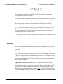
If the retro-reflector assembly moves a distance d, the number of fringes produced is
given by the equation:
mλ = 4nλ d
where:
m is the number of fringes generated by the input laser
λ is the wavelength of input laser beam
nλ is the refractive index of air at the wavelength λ.
The above equation can be used to determine the wavelength of the laser radiation in
vacuum by measuring d very accurately while counting the number of fringes m, and
substituting the refractive index of air.
The accuracy of such a measurement is limited to the precision in the measurement of d
and our knowledge of nλ. To determine d for high accuracy measurements, a reference
HeNe laser with an accurately known wavelength is built into the instrument. The
reference laser beam is directed along exactly the same path as the input laser through
the Michelson interferometer, but in the opposite direction so it can be detected on a
separate reference photodetector. For the reference laser beam, we can write the
equation:
mo λo = 4 no d
Combining the above two equations gives:
08115-M-00 Rev E
4-1
WA-1100/WA-1600 Wavemeter Operating Manual
4 Theory of Operation & Calibration
n
m
λ = é o mù é λ n ù λ o
êë
úû êë
oú
û
Therefore, the wavelength of the input laser beam is equal to the ratio of the number of
fringes recorded for each laser multiplied by a refractive index correction and the
wavelength of the reference laser beam.
The accuracy of the wavelength measurement is dependent on the terms in the equation
above:
mo / m - this ratio is calculated from the number of fringes generated for each laser over
the distance scanned by the retro-reflector assembly. If the fringes are accurately
subdivided, the numerator and denominator do not have to be integers.
nλ / no - this ratio accounts for the difference in optical distances traveled by two laser
beams with different wavelengths. Such a dispersion correction is necessary to determine
the wavelength relative to vacuum. It is dependent on the temperature, pressure and
humidity of the air inside the interferometer.
λo - is the reference laser vacuum wavelength. Its absolute accuracy is fundamental to the
accuracy of the measurement.
Accuracy
The accuracy of the instrument depends fundamentally on the absolute accuracy of the
reference laser, but several other factors can affect the accuracy of the measured
wavelength:
Fringe counting resolution: Computing a wavelength with high accuracy requires that
the precision in the numerator and denominator of the count ratio ( mo/m ) is statistically
sufficient. For the count ratio to have high precision, the number of fringes counted must
be large or the fringes must be accurately subdivided. The WA-1100 and WA-1600 use a
specially designed counter circuit to divide the interferometer fringes more than one
hundred times. This design ensures that the counting statistics are always much higher
than the number of fringes.
Dispersion in the Refractive Index of Air: The vacuum wavelength of the input
radiation is computed from the vacuum wavelength of the reference laser by correcting
for the dispersion (nλ/no) in the refractive index of air. In the WA-1100 and WA-1600,
the dispersion correction for temperature and pressure is calculated from the revised
Edlén equation from Birch and Downs (Metrologia, 30, 155 (1993). If the temperature,
pressure and humidity of the air are known, these calculations have an accuracy of better
than 5 parts in 108 at wavelengths between 600 and 1700 nm.
4-2
08115-M-00 Rev E
WA-1100/WA-1600 Wavemeter Operating Manual
4 Theory of Operation & Calibration
The temperature and pressure are measured inside the instrument and a correction factor
is applied when computing the wavelength. Although humidity is taken into account in
the index calculation, its effect is negligible in the infrared.
For reference, the error in parts per million (ppm) introduced by errors in the
temperature, pressure, or humidity is given approximately by:
∆(nλ/no) = 0.01∆T – 0.004 ∆ ppm
where:
∆T is the temperature error in °C
∆P is the barometric pressure error in mm Hg
Alignment: An accurate measurement depends on the reference laser beam and the input
laser beam passing along exactly the same path through the Michelson interferometer.
The fiber optic input connector is prealigned to ensure that the alignment error is less
than 1 part in 107.
Diffraction: If an aperture anywhere along the laser beam path is made small, diffraction
will change the direction of the light passing through the Michelson interferometer,
possibly causing an additional error. No small apertures are incorporated in the WA1100 and WA-1600 that would introduce diffraction errors greater than 1 part in 107 for
any of the wavelength ranges.
Coherence: In order to achieve a high accuracy wavelength measurement, the bandwidth
of the laser radiation must be narrow. This is because the generation of interference
fringes by a Michelson interferometer is dependent upon the coherence length: Lc = (2π
∆ν)-1, which is inversely proportional to the bandwidth (∆ν) in cm-1.
A narrow bandwidth laser, with a coherence length greater than a few centimeters,
generates a sufficient number of interference fringes to achieve the highest accuracy. If
the laser bandwidth is increased, resulting in a shorter coherence length, the number of
fringes that can be counted is reduced.
A low coherence laser source may have a broad linewidth or operate simultaneously on
two or more closely spaced lines. Three examples of Michelson interferometer fringe
patterns for different laser spectra are depicted in Figure 4-1, Figure 4-2 and Figure 4-3.
The instrument has a Monitor port on the rear panel where signals like these
corresponding to the actual input laser can be observed on an oscilloscope.
08115-M-00 Rev E
4-3
WA-1100/WA-1600 Wavemeter Operating Manual
4 Theory of Operation & Calibration
In these figures, the digital logic signals labeled Trigger, Zero Optical Path (ZOP), and
Window below each fringe pattern identify the timing and extent of each measurement
interval. These 5 volt logic signals can also be observed at the Monitor port. Trigger
defines the largest measurement range possible for the particular instrument model. The
rising transition of the ZOP signal defines the point in the scan where the two arms of the
interferometer are exactly equal in optical path length. The envelope of the fringe pattern
will always exhibit a maximum amplitude at the ZOP point, independent of the linewidth
or mode structure. Window is a signal that identifies where the envelope of the fringe
signal exceeds approximately 1 volt p-p amplitude. After a Window occurs that includes
the ZOP point, no further Windows will be generated. When multiple Windows occur,
such as in Figure 4-3, only one “Valid Window” that includes the ZOP point is used in
the measurement.
A narrow linewidth laser produces fringes throughout the entire Trigger interval as
shown in Figure 4-3. In this case, the Window interval is the maximum length allowed
by the Trigger interval, and the highest precision measurement is made.
Fringe Signal
Laser Spectrum
Monochromatic
Trigger
ZOP
Window
Figure 4-1.
Fringe signal and measurement window for a monochromatic input
laser with a narrow linewidth
Figure 4-2 shows that when the laser linewidth is broad, the envelope of the fringes does
not extend as far as the Trigger interval on either side of the ZOP point. The Window
interval is shortened to include only the number of fringes with sufficient amplitude to be
reliably counted and the precision of the measurement is reduced accordingly.
4-4
08115-M-00 Rev E
WA-1100/WA-1600 Wavemeter Operating Manual
Laser Spectrum
4 Theory of Operation & Calibration
Fringe Signal
Broad linewidth
Trigger
ZOP
Window
Figure 4-2.
Fringe signal and measurement window for a broad linewidth input
laser
Figure 4-3 shows an example of a bi-modal laser with two strong spectral lines. This
laser produces a fringe pattern that exhibits beating between the two laser frequencies.
Since the fringe amplitude goes to zero on either side of the ZOP, only the center fringe
envelope can be used. Prior to the valid Window surrounding the ZOP point, other
windows may occur but these are ignored for measurement purposes.
Laser Spectrum
Fringe Signal
Bi-modal
Trigger
ZOP
Window
Valid Window
Figure 4-3. Fringe signal and measurement window for a bi-modal input laser
When the number of fringes is reduced by increased bandwidth or lack of coherence in
the laser source, the accuracy of the wavelength measurement is also reduced. Typically,
an increased bandwidth limits the accuracy of measurement to about 10% of the laser
bandwidth for a single broad line as in Figure 4-2 or to 10% of the mode separation in a
multi-mode laser spectrum as in Figure 4-3. When a laser has a complex mode structure,
the measurement precision will be about 10% of the effective bandwidth and the
wavelength reported will correspond to the intensity weighted average of the spectral
distribution.
08115-M-00 Rev E
4-5
WA-1100/WA-1600 Wavemeter Operating Manual
4 Theory of Operation & Calibration
The WA-1100 and WA-1600 have an Auto-resolution feature that automatically adjusts
the precision of the wavelength or frequency measurement according to the laser
bandwidth. Insignificant digits after the decimal point are eliminated. If insignificant
digits occur ahead of the decimal point they are replaced by the “x” character on the
display. The reduction in resolution and number of digits displayed is demonstrated in
Table 4-4.
Table 4-4. Auto-resolution as a function of laser bandwidth.
Laser Bandwidth (∆
∆ν )
Coherence Length (Lc) Auto-resolution Display
∆ν ≤ 1.5 GHz (WA-1600 only)
> 32 mm
0.0001 nm
∆ν ≤ 15 GHz
> 3.2 mm
0.001 nm
∆ν ≤ 150 GHz
> 0.32 mm
0.01 nm
Accuracy Verification
Each WA-1100 and WA-1600 has been verified with a DFB diode laser locked to the
R(3) band of acetylene (12C2H2). The center of this absorption line has been characterized
to 196,832.341 GHz +/- 150 KHz by K. Nakagawa et al. in "Accurate optical frequency
atlas of the 1.5m bands of Acetylene", JOSA, B, 13, 2708 (1996) using an absorption
line of Rubidium as the reference standard. The absorption line along with the laser’s
frequency locking circuit has been characterized to provide accuracy verification to
within the limits required to verify the average wavelength reading to the accuracy
specified for each model.
Calibration
As described earlier, accuracy is assured by the built-in continuous calibration from the
on-board internal reference laser. In effect, the instrument is self-calibrating and can be
expected to give years of accurate data. However, factors such as alignment can affect
wavelength measurement. Although the rugged and compact optical housing is designed
to minimize misalignments or other factors affecting accuracy due to aging and repeated
handling, you may choose to consider a factory reverification. The decision to verify, if
at all, depends on your existing procedures considering industry certifications such as
ISO. If you do not have such procedures in place, consider the tradeoff between the time
and cost of reverification versus data uncertainty and discuss these with your EXFO
representative.
4-6
08115-M-00 Rev E
WA-1100/WA-1600 Wavemeter Operating Manual
Appendix A Specifications and Labeling
Appendix A. Specifications & Labeling
This Appendix provides specifications, dimensional drawings and labeling information.
Table A-1. Specifications
WA-1100
WA-1600
Accuracy
±1 ppm (± 1.5 pm @ 1550 nm)
±0.2 ppm (± 0.30 pm @ 1550
nm)
Resolution (Display)
0.001 nm
0.0001 nm
Input Sensitivity
-30 dBm (1µW) 1200 - 1700 nm, -20 dBm below 1200 nm
Max Input Power
10 dBm (10 mW)
Optical Power Measurement
Accuracy
±0.5dB (±10%)
Resolution
±0.05dB (±1%)
Max. Input Power
10 mW (100mW with external attenuator)
General
Design
Scanning Michelson interferometer design
Input
Fiber Optic Coupler, FC/APC standard
Wavelength Range
700-1700 nm
Measurement Rate
10 per second
Temperature Range
15-30 °C (ambient temperature)
Pressure Range
500 - 900 mm Hg
Dimensions
417 mm ×356 mm × 89 mm
Communications Interface
RS-232 and IEEE 488.2 standard
Electrical Power Consumption
45 Watts at 110 V
Weight
12 Kg (25 lbs)
Power Requirements
90-260 VAC, 50/60 Hz
Fuse
2A, 250 V, time-delay, 5 x 20mm (1/4" x 1 1/4")
1 per second
60 Watts at 110 V
*Sensitivity defines the optical input power required over most of the wavelength range.
More power may be necessary at either end of the range, depending on the photodetector.
08115-M-00 Rev E
A-1
WA-1100/WA-1600 Wavemeter Operating Manual
Appendix A Specifications and Labeling
Dimensional Drawing
Figure A-1. Dimensions
Rack Mounting Option
The WA-1100/1600 can be mounted in a standard 19" electronics rack by attaching the
rack mounting brackets as shown below.
When the WA-1100/1600 is mounted in an enclosed rack, be careful not to block the fan
on the rear panel and provide adequate ventilation inside the rack to prevent overheating.
For proper fit, you may want to remove the feet under the chassis.
CAUTION
A-2
If you remove the feet, DO NOT reinsert the screws or damage to the
internal components of the wavemeter can occur.
08115-M-00 Rev E
WA-1100/WA-1600 Wavemeter Operating Manual
Appendix B Warranty & Service
Appendix B. Warranty & Service
Warranty
The WA-1100 and WA-1600 are warranted against defects in material and workmanship
for a period of one year after date of delivery. Optical components are warranted for 90
days. During the warranty period, EXFO will repair, or at its option, replace parts that
prove to be defective when the instrument is returned prepaid to EXFO. Before
returning an instrument always call EXFO for return authorization. The warranty
will not apply if the instrument has been damaged by accident, misuse, or as a result of
modification by persons other than EXFO personnel.
It is important to call EXFO or your local sales representative in advance of returning a
unit, for a Return Authorization Number (RA#). This will ensure the prompt handling of
the repair, as well as provide important tracking information.
The liability of EXFO, (except as to title) arising out of supplying of said product, or its
use, whether under the foregoing warranty, a claim of negligence, or otherwise, shall not
in any case exceed the cost of correcting defects in the products as herein provided.
Upon expiration of the warranty period specified herein, all liability shall terminate. The
foregoing shall constitute the sole remedy of the buyer. In no event shall the seller be
liable for consequential or special damages.
Service
There are no user serviceable parts inside the WA-1100 and WA-1600. Adjusting parts
inside the instrument can affect the accuracy of the instrument. If you adjust parts, you
will need to verify the accuracy of the measurements.
08115-M-00 Rev E
B-1
WA-1100 & WA-1600 Wavemeter Operating Manual
B-2
Appendix B Warranty & Service
08115-M-00 Rev E
WA-1100/WA-1600 Wavemeter Operating Manual
Appendix C Error & Status Messages
Appendix C. Error & Status Messages
The instrument continually checks the quality of the signal it is analyzing and reports
messages for any unusual conditions that might affect the precision of the measurement.
There are two types of messages. In most cases, Error Messages will prevent data from
being reported. These are displayed in the Display Screens. The error messages will also
be reported as Status Messages that will be reported in the Status Screen or can be
queried through remote communications. Some other status messages may not prevent
data from being reported, and indicate that there may be unusual operation of the laser
under test and are to simply caution the user that a problem may exist.
08115-M-00 Rev E
C-1
WA-1100/WA-1600 Wavemeter Operating Manual
Appendix C Error & Status Messages
Error Messages
In the following table, the error messages are described with a cross-reference to the
status screen reference code. The error messages are shown in order of how there would
appear if there were multiple errors.
Table C-1. Error Messages
Display Message
Cause/Solution
Status Screen
Reference
“Loading Default
Settings”
Indicates the original calibration and set-up data has been
corrupted and default values will be used.
none
"Reference Laser: Over
Temperature"
WA-1600 only. The reference laser stabilization circuit is
indicating an over temperature condition. Turn the
instrument off, wait 15 minutes and power up again. If the
problem persists, contact EXFO Service.
00000002
"Reference Laser:
Calibration Error"
WA-1600 only, reference laser peak power outside of 6085% range necessary for proper operation. Recalibration
is necessary. Contact EXFO Service.
00040000
"Reference Laser: Not
Stabilized"
WA-1600 only. This message is normal on power up for
up to 7 minutes. The display shows warm-up time.
Turning power off and on again will restart the warm-up
timer. If this condition occurs after initial warm-up then
contact EXFO Service.
00000001
"Scan Engine: No
Trigger"
Interferometer scan motion error. Either the scan
assembly is not moving or the scan timing detector is
malfunctioning. Contact EXFO Service.
00000080
"Temperature/Pressure
Sensor: Out of Range"
The pressure or temperature reading is out of range; the
normal pressure range is 500 mm Hg to 900 mm Hg and
the normal temperature range is 1°C to 50°C. A
temperature or pressure reading of 0 usually indicates the
sensor is not connected or has a broken wire. Contact
EXFO Service.
00001000 and
00002000
"Reference Laser: No
Fringes Detected"
Detector failure or insufficient signal amplitude from the
00000004
reference laser. This may be due to a decrease in reference
laser power or a major misalignment of the internal
optics. Contact EXFO Service.
"Input Laser: Intensity
Too Low"
The input laser signal observed at the Monitor output
must exceed 1.5 volts p-p amplitude. Set gain to auto.
Check input laser power. Increase the intensity of the
input laser beam entering the instrument.
00000100
"Input Laser:
Wavelength Out Of
Range"
Check that the laser is operating within the specified
wavelength range: 700-1700 nm.
00008000
C-2
08115-M-00 Rev E
WA-1100/WA-1600 Wavemeter Operating Manual
Appendix C Error & Status Messages
Status Messages
The following table describes the complete set of status messages that can appear in the status
screen. The messages are listed in numerical order.
Table C-2. Status Messages
Status
Message
Description
Solution
Load default settings
Indicates the original calibration and set-up data has
been corrupted and default values will be used.
00000001
WA-1600 only, reference laser is not
stabilized.
This message is normal on power up of the WA1600. The display shows warm-up time. Turning
power off and on again will restart the warm-up
timer. If this condition occurs after initial warm-up
then contact EXFO Service.
00000002
WA-1600 only, reference laser is
over temperature.
The laser stabilization circuit is indicating an over
temperature condition. Turn the instrument off, wait
15 minutes and power up again. It the problem
persists, contact EXFO Service.
00000004
Detector failure or insufficient signal
amplitude from the reference laser.
This may be due to a decrease in reference laser
power or a major misalignment of the internal optics.
Contact EXFO service.
00000008
Intermittent signal from the reference
laser during the measurement
window.
Reference laser signal at the Monitor output should
exceed 2.0 volts p-p throughout the measurement
window.
This may be due to partial misalignment of the
instrument internal optics.
00000020
EEPROM read failure. Problem
occurs on power up or when
restoring.
Turn the instrument off, wait a few moments, and
turn the instrument back on.
00000040
Static RAM read/write failure. This
error may sometimes occur on power
up.
Turn the instrument off, wait a few moments, turn
the instrument back on. If the problem persists
contact EXFO Service.
00000080
Interferometer scan motion error.
Either the scan assembly is not moving or the scan
timing detector is malfunctioning. Contact EXFO
Service.
00000100
Input signal (fringe amplitude) is too
low.
The input laser signal observed at the Monitor output
must exceed 1.5 volts p-p amplitude. Set gain to
auto. Check input laser power. Increase the intensity
of the input laser beam entering the instrument.
00000200
00000400
00000800
Counting errors.
Check input laser for intensity or frequency
instability. If the error persists, contact EXFO
Service.
00001000
Pressure reading is out of range;
range is 500 mm Hg to 900 mm Hg.
If the problem persists contact EXFO Service.
08115-M-00 Rev E
If the problem persists contact EXFO Service.
C-3
WA-1100/WA-1600 Wavemeter Operating Manual
Appendix C Error & Status Messages
00002000
Temperature reading is out of range;
range is 1°C to 50°C.
A temperature reading of 0°C usually indicates the
temperature sensor is not connected or has a broken
wire. If the problem persists contact EXFO Service.
00004000
Input Laser Power error, power is out
of range
Check that the laser is operating within the specified
power range. If no wavelength is indicated, then
1550 nm is assumed in the power calculation.
00008000
The wavelength (or frequency)
measurement is out of the range for
the model setting.
Check that the laser is operating within the specified
wavelength range: 700-1700 nm.
00010000
Power Null failure.
The background power reading is above the
threshold for the power null function. Make sure an
input laser is removed from the instrument and the
fiber connector cap is on.
00040000
WA-1600 only, reference laser peak
power outside of 70-80% range
necessary for proper operation.
Recalibration is necessary. Contact EXFO Service.
00080000
Input power too high.
Check if input laser is above the specified maximum
input power.
00100000
00200000
00400000
00800000
Internal communications error.
If persistent, contact EXFO Service
C-4
08115-M-00 Rev E
WA-1100 & WA-1600 Wavemeter Operating Manual
Appendix D Rear Panel Controls
Appendix D. Rear Panel Controls
GPIB Port
The instrument has a GPIB communications port on the back panel as shown in Figure
D-1. The GPIB port uses the standard IEEE-488 connector, with the pinout described in
Table D-1.
Figure D-1. GPIB Interface Connector
Table D-1. Standard IEEE-488 Connector Pinout
08115-M-00 Rev E
Pin
Signal
Pin
Signal
Number
Name
Number
Name
1
DIO1
13
DIO5
2
DIO2
14
DIO6
3
DIO3
15
DIO7
4
DIO4
16
DIO8
5
EOI
17
REN
6
DAV
18
GND (TW W/ DAV)
7
NRFD
19
GND (TW W/ NRFD)
8
NDAC
20
GND (TW W/ NDAC)
9
IFC
21
GND (TW W/ FC)
10
SRQ
22
GND (TW W/ SRQ)
11
ATN
23
GND (TW W/ ATN)
12
SHIELD
24
SIGNAL GROUND
D-1
WA-1100 & WA-1600 Wavemeter Operating Manual
Appendix D Rear Panel Controls
RS-232 Serial Interface Connector
The RS-232 port is a 9-pin, female, D-sub style connector, with the pinout described in
Table 3-1. The connector housing provides connection to the earth ground inside the
instrument.
The pin configuration complements that of the PC/AT. To connect the instrument to a
PC/AT, use a serial extension cable with 1:1 pin correlation. To facilitate the connecting
of the serial port, use the signal descriptions (H = Active).
Figure D-2. RS-232 Serial Interface Connector
Table D-2. RS-232 Serial Port Pinout
Pin
Number
Signal
Name
Signal Source
Description
1
-
-
N/C
2
TxD
WA-1100/1600
Transmit Data. Data from the instrument is output on this signal
pin.
3
RxD
User
Receive Data. Data from the user is received on this signal pin.
4
DSR
User
Data Set Ready. This input signal must be held active by the user
for the instrument to consider the serial port connected to an
external device.
5
GND
-
Signal Ground. Required for proper RS-232 operation.
6
DTR
WA-1100/1600
Data Terminal Ready. This output signal is active whenever the
instrument is powered and is not in internal reset.
7
CTS
User
Clear To Send. An input signal indicates to the instrument when
the user device is able to accept additional data.
8
RTS
WA-1100/1600
Request To Send. The instrument makes this signal active as long
as its internal command buffer has room in it. When the internal
command buffer is full, the instrument sets RTS inactive.
9
-
-
N/C
D-2
08115-M-00 Rev E
WA-1100 & WA-1600 Wavemeter Operating Manual
Appendix D Rear Panel Controls
Signal Monitor Connector
The Signal Monitor connector on the back panel of the instrument provides a
combination of analog and digital signals for observing the fringe signals and
measurement timing signals using an oscilloscope. The signals have the characteristics
described in Table D-1.
The Signal Monitor output is a 15-pin, female, D-sub style connector shown in Figure D1 and with the pinout described in Table D-2.
Examples of these signals for different input laser characteristics are described and
shown in Section 4 of this manual.
Table D-3. Signal Monitor Characteristics
Analog Signals
Digital (TTL) Signals
Output Voltage
± 7 V maximum
VOL = 0.4V max,
Output Current
100 mA maximum
IOL = 16 mA max, IOH = -0.4 mA
Output Timing
NA
tr ≤ 7 nsec, tf ≤ 7 nsec
VOH = 2.4V min
Figure D-3. Signal Monitor Output Connector
08115-M-00 Rev E
D-3
WA-1100 & WA-1600 Wavemeter Operating Manual
Appendix D Rear Panel Controls
Table D-4. Monitor Pinout
Pin
Number
Signal Name
Signal
Type
Description
1
INPUT
Analog
Input laser sinusoidal fringe signal.
2
REFERENCE
Analog
Reference laser sinusoidal fringe signal.
3
VREF
TTL
Valid reference laser fringe amplitude.
4
ZOP1 Raw
5
TRIGGER
TTL
Scanning Window Trigger is a digital pulse with a duration that
defines the maximum measurement interval for the interferometer
scan. It goes active (H = active) during the allowed measurement
interval.
6
DGND
-
Digital Ground
7
1 TRIG
8
ZOP
TTL
Zero Optical Path (ZOP) is a digital pulse derived from the
interferometer scanner that produces a low to high transition at the
point in the scan where the difference between the two optical
paths in the interferometer is zero.
9
AGND
-
Analog Ground
10
AGND
-
Analog Ground
11
N/C
12
N/C
13
N/C
14
DGND
-
Digital Ground
15
WINDOW
TTL
Scanning Window digital output is derived from the amplitude of
the input laser fringe signal. When the p-p amplitude of this signal
exceeds 1 volt, within the Trigger interval and before or spanning
the ZOP transition, the Window is active (H = active). Depending
on the character of the input laser fringes, there may be several
Windows during a Trigger, but the first Window period to
terminate after the ZOP transition is the only “Valid Window” used
for the measurement.
D-4
08115-M-00 Rev E
WA-1100 & WA-1600 Wavemeter Operating Manual
lndex
Index
A
accuracy, 4-2
Address of GPIB port, 2-6
Auto
gain, 2-4, 2-5
resolution, 2-5
Average, 2-4, 2-5
Avg, 2-4
B
Baud, 2-6
Brightness, 2-6
C
change display information, 2-2
Cleaning
Fan Filter, 1-4
Fiber End, 1-3
Cleaning a Fiber Optic Connector,
1-3
Cleaning a Universal Connector,
1-3
Cleaning, fiber end, 1-3
Commands
CALCulate, 3-10
DISPlay, 3-12
Measurement, 3-8
SENSe, 3-14
STATus, 3-16
SYSTem, 3-18
TRIGger, 3-19
UNIT, 3-20
Communications setup screen, 2-5
components, 1-2
Configuration setup screen, 2-5
connector
GPIB, D-1
monitor, D-2
RS-232, D-2
D
display
on instrument, 2-1
screens, 2-3
DISPLAY Button, 2-1
E
Error Message, 2-4
error messages, C-1
08115-M-00 Rev E
F
Fan Filter Cleaning, 1-4
Fiber End Cleaning, 1-3
Fiber Optic Connector, 1-3
Fixed gain, 2-4, 2-5
front panel, 2-1
G
Gain, 2-4, 2-5
GPIB
connector, D-1
enable/disable, 2-6
H
Handshaking, 2-6
I
IEEE-488, D-1
Information setup screen, 2-5
L
laser power current, 2-4
lockout. See Remote Lockout
M
Main display screen, 2-3
Mediium, 2-4
monitor signal, D-2
P
Poffs, 2-4
Power, 2-4
current, 2-4
display screen, 2-3
offset, 2-4, 2-5
switch, 2-1
Power Null, 2-5
R
Rack Mounting Option, A-2
Remote Lockout, 2-2, 2-6
Reset, 2-4
Resolution, 2-5
Restore All, 2-6
restore parameters, 2-2
return authorization, B-1
RS-232
connector, D-2
enable/disable, 2-6
S
Save All, 2-6
save parameters, 2-2
I
Index
WA-1100 & WA-1600 Wavemeter Operating Manual
SCPI, 3-1
screens
display, 2-3
setup, 2-5
SELECT Button, 2-1
service, B-1
set up instrument, 1-2
SETUP Button, 2-1
Setup screens, 2-5
signal
GPIB, D-1
monitor, D-2
RS-232, D-2
specifications, A-1
standard air, 2-4
Status screen, 2-5
II
U
units. See specific parameter's
units
Universal Connector, 1-3
V
vacuum, 2-4
Vacuum, 2-4
W
warranty, B-1
Wavelength
current, 2-4
display screen, 2-3
X
Xon/Xoff, 2-6
08115-M-00 Rev E
Declaration of Conformity
Manufacturer’s Name:
EXFO Burleigh Products Group Inc.
Manufacturer’s Address:
7647 Main St. Fishers
Victor, NY 14564-8909
USA
declares this product:
Product Name:
Wavemeter
Model Number(s):
WA-1100
WA-1600
conforms to the following standards:
Safety: EN-61010-1: IEC 1010-1
EMC:
EN-50081-1: EN-55011; Group 1, Class A : Emissions
EN-50082-1: IEC 1000-4-2: ESD Immunity; 2kV CD, 2kV AD
IEC 1000-4-3: RFI Immunity; 3V/m, 27-500 MHz, Class II
IEC 1000-4-4: Electrical Fast Transient Immunity; 0.5 kV
IEC 1000-4-5: High Voltage Surge Immunity; 0.5 kV
Supplementary Information:
“The product complies with the requirements of
the Low Voltage Directive 73/23/EEC and
the EMC Directive 89/336/EEC.”
European Sales Office:
Scientifica Ltd.
9 Allied Business Center, Coldharbour Lane
Harpenden, Herts, AL5 4UT, UK
Date of Issue:
September, 1998
signed:
David J. Farrell, President
EXFO Burleigh Products Group Inc.
7647 Main Street Fishers
Victor, NY 14564-8909
Tel. (585) 924-9355
Fax. (585) 924-9072
WA1100/1600
08115-M-00