1
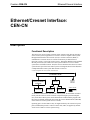
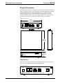
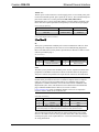
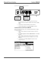
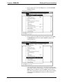
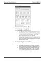
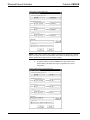
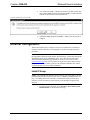
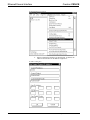
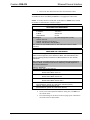
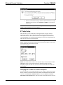
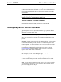
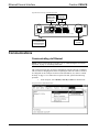
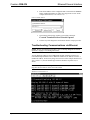
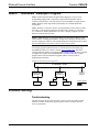
This document was prepared and written by the Technical Documentation department at:
Crestron Electronics, Inc.
15 Volvo Drive
Rockleigh, NJ 07647
1-888-CRESTRON
Crestron CEN-CN
Ethernet/Cresnet Interface
Contents
Ethernet/Cresnet Interface: CEN-CN
Description
Functional Description
Physical Description
Leading Specifications
Cresnet Network Wiring
Configuration Setup
Installing Crestron Development Tools
Obtaining Communications
Troubleshooting Communications
Updating the CEN-CN
Ethernet Configuration
Initial IP Setup
IP Table Setup
Hookup Diagram for Normal Operation
Communications
Communicating via Ethernet
Troubleshooting Communications via Ethernet
SIMPL™ Windows® Example Program
Problem Solving
Troubleshooting
Further Inquiries
Future Updates
Return and Warranty Policies
Merchandise Returns / Repair Service
CRESTRON Limited Warranty
Glossary of Terms
Operations Guide - DOC. 5721
1
1
1
2
4
5
6
6
7
10
11
13
13
16
17
18
18
19
20
20
20
21
21
22
22
22
23
Contents • i
Crestron CEN-CN
Ethernet/Cresnet Interface
Ethernet/Cresnet Interface:
CEN-CN
Description
Functional Description
The CEN-CN is used to connect Crestron remote control system (herein referred to
as the Cresnet system) equipment to a Crestron e-Control™ capable control system
through an Ethernet/local area network (LAN) or wide area network (WAN). A
combination of Crestron devices in a remote location may be hard-wired to a
CEN-CN to create a “CEN-CN Cresnet system”. Through an Ethernet using standard
Internet protocol (IP), the CEN-CN Cresnet system connects to a “host” control
system that is in another location. Thus, the devices attached to the CEN-CN Cresnet
system become part of the host control system. The diagram shown below illustrates
a sample Ethernet/Cresnet system that contains a CEN-CN.
e-Control Capable Cresnet System with CEN-CN
ETHERNET HUB
HOST CONTROL
SYSTEM (ETHERNET
CAPABLE)
CRESNET
PERIPHERAL
UPLINK TO
REST OF
ETHERNET
CEN-CN
CRESNET
PERIPHERAL
CRESNET
PERIPHERAL
WIRING LEGEND
CRESNET
ETHERNET
To establish communication with the host control system, IP information is loaded
locally into the CEN-CN via the Crestron Viewport through a personal computer
(PC). In the host control system, the IP information is loaded and the program with
the CEN-CN defined on Ethernet that contain the Cresnet identifications (NET IDs)
of the CEN-CN Cresnet system devices is loaded.
Operating power for the CEN-CN may be supplied either by the external AC power
pack (included) that provides 12 direct current volts (VDC) or supplied by 24VDC
via the 4-wire CEN-CN Cresnet system wiring.
Operations Guide - DOC. 5721
Ethernet/Cresnet Interface: CEN-CN • 1
Ethernet/Cresnet Interface
Crestron CEN-CN
Physical Description
The CEN-CN, shown below, is housed in a black enclosure with silk-screened labels
on the front and rear panels. On the front panel are six light-emitting diodes (LEDs)
for indicating the status of the unit, the attached device(s), and the connected
Ethernet. All connections are made through on the rear panel ports, a Crestron
6-conductor modular cable and two 4-pin connector plugs are provided. There are
four rubber feet on the base of the unit for stability and to prevent slippage.
CEN-CN Physical Views
7.07 in
(17.95 cm)
12VDC
.5A
PC
NET
NET
NET
24 Y Z G
24 Y Z G
ETHERNET
CRESTRON ELECTRONICS INC. ROCKLEIGH, N.J. 07647 USA
6.32 in
(16.06 cm)
ETHERNET/CRESNET INTERFACE
ETHERNET
PWR NET
RXD
CRESTRON
TXD
LNK
ERR
1.70 in
(4.32 cm)
CEN-CN
CEN-CN Ports
Each CEN-CN rear panel port has a silk-screened label. For the descriptions of the
ports, refer to the diagram below and following paragraphs.
CEN-CN Rear Panel
12VDC
.5A
PC
NET
NET
NET
24 Y Z G
24 Y Z G
ETHERNET
CRESTRON ELECTRONICS INC. ROCKLEIGH, N.J. 07647 USA
2 • Ethernet/Cresnet Interface: CEN-CN
Operations Guide - DOC. 5721
Crestron CEN-CN
Ethernet/Cresnet Interface
12VDC .5 A
This DC power socket connector is used to supply power via an external power pack.
Crestron recommends specific power packs for its devices. The recommended power
pack for the CEN-CN is Crestron part number PW-1205 (PWI-1210 for
international use). If a power pack other than this Crestron model is obtained, verify
that it meets the required specifications and polarity as shown after this paragraph.
Power Pack Specifications
CRESTRON POWER PACK
INPUT SPECS
OUTPUT SPECS
PW-1205
PWI-1210
120VAC~60 hertz (Hz)
230VAC~50Hz
12VDC .5A
12VDC 1A
Power Pack Output Connector Polarity
PC
This 6-pin, 6-position RJ11 modular jack is used to communicate with a PC when
performing the configuration of the CEN-CN or for troubleshooting diagnostics.
Refer to the table below for the pinouts. Specifications to fabricate a CEN-CN to PC
cable are provided on page 7.
PC Port Pinouts
PIN
DESCRIPTION
PIN
DESCRIPTION
1
2
3
CTS (Clear to Send)
GND
RxD (Received Data)
4
5
6
TxD (Transmitted Data)
RTS (Request to Send)
Not Connected
NET
The NET 6-pin, 6-position RJ11 modular jack is used for expansion to SmarTouch
peripheral(s) or modular Cresnet devices. Refer to the table below for the pinouts.
This port is connected in parallel to the 4-pin network connectors described below.
CAUTION: If making connections to RJ11 ports, use the Crestron 6-conductor
modular cable provided, DO NOT use 6-conductor telephone cables. Telephone
cables are wired in a crisscross fashion and are not compatible with Crestron
equipment. For further information, refer to the latest revision of Modular Cable
Requirements (Doc. 5682). This document can be obtained from the Downloads
page (CABLES and MANUAL Libraries) of Crestron’s website
(www.crestron.com). Search for MODULAR.PDF. New users are required to
register in order to obtain access to the FTP site.
6-Pin NET Port Pinouts
PIN
DESCRIPTION
PIN
DESCRIPTION
1
2
3
+24VDC
+24VDC
NET+ (Cresnet Y data)
4
5
6
NET- (Cresnet Z data)
GND
GND
NOTE: The +24VDC at this port is available only if supplied via Cresnet wiring connected to
the 4-wire NET port(s). The external AC power pack does not supply power to this port.
The two NET 4-pin network connectors are used to connect the 4-wire Cresnet
devices to the CEN-CN. Power can be provided via the NET connection and the
external power pack is not required. Refer to “Cresnet Network Wiring” on page 5
for wiring information.
Operations Guide - DOC. 5721
Ethernet/Cresnet Interface: CEN-CN • 3
Ethernet/Cresnet Interface
Crestron CEN-CN
ETHERNET
This 8-pin, 8-position RJ45 port connects the CEN-CN to a 10BaseT Ethernet/LAN
or WAN via a hub. Refer to the table below for the pinouts. A standard (straight,
non-cross-over type) Ethernet cable is required, but not supplied.
NOTE: This port should NOT be connected to the UPLINK port of an Ethernet hub.
Ethernet Port Pinouts
PIN
DESCRIPTION
PIN
DESCRIPTION
1
2
3
4
TX- (Transmit -)
TX+ (Transmit +)
RX+ (Receive +)
Not Connected
5
6
7
8
Not Connected
RX- (Receive -)
Not Connected
Not Connected
CEN-CN Indicators
There are six LED indicators located on the front panel of the CEN-CN. For the
descriptions of the front panel indicators, refer to the diagram below and the
following paragraphs.
CEN-CN Front Panel
ETHERNET/CRESNET INTERFACE
P W R NET
CRESTRON
ETHERNET
RXD
TXD
LNK
ERR
CEN-CN
PWR
This LED (green) illuminates when operating power is supplied to the CEN-CN.
Operating power may be supplied either by the external AC power pack (included)
that provides 12VDC or supplied by 24VDC via the 4-wire CEN-CN Cresnet system
wiring.
NET
This LED (yellow) illuminates when communication with the CEN-CN Cresnet
system devices and the CEN-CN is occurring. The connections to these devices are
made through the rear panel NET ports.
ETHERNET
These four front panel LEDs are active while the CEN-CN is connected to a LAN or
WAN through the rear panel ETHERNET port. The RXD (green) LED illuminates
during reception of Ethernet data and TXD (green) illuminates during transmission
of Ethernet data. The LNK (yellow) LED illuminates when there are attachments to
the Ethernet network and ERR (red) illuminates when an Ethernet protocol error is
detected.
Leading Specifications
The table on the next page provides a summary of leading specifications for the
CEN-CN. Dimensions and weight are rounded to the nearest hundredth unit.
4 • Ethernet/Cresnet Interface: CEN-CN
Operations Guide - DOC. 5721
Crestron CEN-CN
Ethernet/Cresnet Interface
Leading Specifications of the CEN-CN
SPECIFICATION
Power Requirements
Ethernet Network Type
Ethernet Network Protocols
SIMPL™ Windows®
CEN-CN Update File
CNMSX-AV/Pro Update File
CNRACKX-DP Update File
Dimensions & Weight
DETAILS
12VDC, external power pack or
24VDC, .25A, 6W, network
10BaseT
TCP/IP, UDP/IP, ICMP (Ping), & CIP
Version 1.52.00 or later. 1
Version 51189N.UPZ or later. 2
Version 51190X.UPZ or later. 2
Version 51190W.UPZ or later. 2
Height: 1.70 in (4.32 cm)
Width: 7.07 in (17.95 cm)
Depth: 6.32 in (16.06 cm)
Weight: 1.87 lb (0.85 kg)
1
Although the CEN-CN does not support a program being loaded, the version listed
is required by the host control system to support the CEN-CN. The latest software
version can be obtained from the Downloads page (SIMPLWIN Library) of
Crestron’s website (www.crestron.com). New users are required to register in order
to obtain access to the FTP site.
2
Filenames for update files have a UPZ extension and can be obtained from the
Downloads page (OPSYS Library) of Crestron’s website.
As of the date of manufacture, this unit has been tested and found to comply with
specifications for CE marking.
NOTE: This device complies with part 15 of the FCC rules. Operation is subject to
the following two conditions: (1) this device may not cause harmful interference, and
(2) this device must accept any interference received, including interference that may
cause undesired operation.
Cresnet Network Wiring
NOTE: If making category 5 connections to the Cresnet peripherals, refer to the
latest revision of the Cresnet Mini Network CAT 5 Interconnect Drawing (Doc.
5819). This document can be obtained from the Downloads page (CABLES and
MANUAL Libraries) of Crestron’s website (www.crestron.com). Search for
CAT5.PDF. New users are required to register to obtain access to the FTP site.
NOTE: If making modular connections to devices in the Cresnet system, review the
latest revision of the Network Modular Cable Requirements (Doc. 5682). This
document can be obtained from the Downloads page (CABLES and MANUAL
Libraries) of Crestron’s website (www.crestron.com). Search for MODULAR.PDF.
When calculating the wire gauge for a particular Cresnet run, the length of the run
and the load factor of each network unit to be connected must be taken into
consideration. If Cresnet units are to be daisy-chained on the run, the load factor of
each unit to be daisy-chained must be added together to determine the load factor of
the entire chain. If the unit is a home-run from a Crestron system power supply
Operations Guide - DOC. 5721
Ethernet/Cresnet Interface: CEN-CN • 5
Ethernet/Cresnet Interface
Crestron CEN-CN
network port, the load factor of that unit is the load factor of the entire run. The
length of the run in feet and the load factor of the run should be used in the following
resistance equation to calculate the value on the right side of the equation.
Resistance Equation
R <
40,000
L x LF
Where: R = Resistance (refer to next table).
L = Length of run (or chain) in feet.
LF = Load factor of entire run (or chain).
The required wire gauge should be chosen such that the resistance value is less than
the value calculated in the resistance equation. Refer to the table below.
Wire Gauge Values
RESISTANCE (R)
WIRE GAUGE
4
6
10
15
13
16
18
20
22
24 (Double-CAT 5)
NOTE: All 4-wire Cresnet wiring must consist of two twisted-pairs. One twisted
pair is the +24V conductor and the GND conductor and the other twisted pair is the
Y conductor and the Z conductor.
NOTE: When daisy-chaining Cresnet units via 4-wire Cresnet wiring, always twist
the ends of the incoming wire and outgoing wire which share a pin on the network
connector. After twisting the ends, tin the twisted connection with solder. Apply
solder only to the ends of the twisted wires. Avoid tinning too far up the wires or the
end becomes brittle. After tinning the twisted ends, insert the tinned connection into
the Cresnet connector and tighten the retaining screw. Repeat the procedure for the
other three conductors.
Configuration Setup
To configure the CEN-CN, a local PC that contains a Crestron Viewport is required.
The Viewport is one of the development tools that is part of Crestron’s SIMPL
Windows or VisionTools Pro-e (VT Pro-e) control software applications.
Installing Crestron Development Tools
Crestron control software is available in an electronic form; CD-ROM, email, or
from Crestron’s website. Regardless of how and from where the software is
obtained, this section provides the necessary installation steps.
NOTE: The latest versions of these applications are available from Crestron’s
website (www.crestron.com). Crestron ControlCD also contains a version (which
may not be as current as the website version). To obtain a free copy of the CD-ROM,
contact Crestron at 1-888-CRESTRON [1-888-273-7876]. Alternatively, complete a
literature request from the Crestron website to obtain one.
6 • Ethernet/Cresnet Interface: CEN-CN
Operations Guide - DOC. 5721
Crestron CEN-CN
Ethernet/Cresnet Interface
Before installing any development tools, confirm that all other applications such as
Microsoft® Office, etc. are closed. The website and CD provide instructions for
installing the various tools. When initiating a custom install from the CD, the user is
presented with a list of the software programs, documentation, and other resources.
For each item, set or clear a checkbox to the left of the item to direct the installation
program whether to install that component onto the hard drive. The size of the each
item installed determines how much disk space is required. Each development tool
contains a help file that can be opened from the Help pull-down menu. Refer to these
files for additional information.
Obtaining Communications
To configure the CEN-CN, it is necessary to first obtain communication with the
device. Communication can be established via the CEN-CN rear panel PC port. To
perform the configuration of the CEN-CN, the provided 6-conductor modular cable
and an RJ11 to DB9F adapter (not supplied) are required. The adapter is available
commercially or contact Crestron customer service for part number 15556. If
obtained, proceed to “Hookup Diagram for Configuration” on page 7.
Configuration Cable Fabrication Specifications
In the event that an RJ11 to DB9F adapter is not available, the table and the diagram
below are provided so that the cable can be fabricated on site.
RJ11 Modular Cable Pinouts
PIN
DESCRIPTION
PIN
DESCRIPTION
1
2
3
CTS (Clear to Send)
GND
RxD (Received Data)
4
5
6
TxD (Transmitted Data)
RTS (Request to Send)
Not Connected
CEN-CN to PC Cable Specification
TO PC
COM PORT
TO CEN-CN
PC PORT
1
PART #
641337
PART #
AWC10152-A
CTS
GND
RxD
TxD
RTS
n/c
1
2
3
4
5
6
REAR VIEW OF
CONNECTOR
2
3
5
6
7
8
9
7
8
1
2
3
4
5
(9-PIN FEMALE)
PART #
748047-1
Hookup Diagram for Configuration
When performing the configuration, refer to the figure on the next page for a typical
connection diagram. Complete the following steps in the order provided to ensure
proper connection.
NOTE: If an RJ11 to DB9F adapter and/or modular cables are not available, refer to
“Configuration Cable Fabrication Specifications” on page 7.
NOTE: Operating power for the CEN-CN may be supplied either by the external
AC power pack (included) that provides 12VDC or supplied by 24VDC via the
4-wire CEN-CN Cresnet system wiring.
Operations Guide - DOC. 5721
Ethernet/Cresnet Interface: CEN-CN • 7
Ethernet/Cresnet Interface
Crestron CEN-CN
Typical Connections When Configuring the CEN-CN
TO PC
COM PORT
PC
12VDC
.5A
NET
ETHERNET
NET
NET
24 Y Z G
24 Y Z G
CRESTRON ELECTRONICS INC. ROCKLEIGH, N.J. 07647 USA
FROM EXTERNAL
AC POWER PACK
TO CRESNET
NETWORK WIRING
(NOT REQUIRED IF OPERATING
POWER IS SUPPLIED
VIA CRESNET WIRING)
(NOT REQUIRED IF OPERATING
POWER IS SUPPLIED VIA
EXTERNAL AC POWER PACK)
1.
If a CEN-CN to PC cable is fabricated, proceed to the next step.
Attach one end of the 6-conductor modular cable to the RJ11 to DB9F
adapter.
2.
Attach the RJ11 connector to the PC port of the CEN-CN.
3.
Attach the DB9 connector to an available COM port on the PC.
Communication via PC Port of CEN-CN
Before performing this procedure, refer to “Obtaining Communications” on page 7
for cabling instructions.
1.
Make sure that no programs accessing the COM port of the PC are
running.
2.
Select Start | Programs | Crestron | SIMPL Windows to start SIMPL
Windows.
3.
SIMPL Windows responds with an opening splash screen and may
display the “What do you want to do?” dialog box. If so, close the
dialog box.
4.
As shown below, select Tools | Viewport to open the Crestron
Viewport dialog box.
Accessing the Viewport
8 • Ethernet/Cresnet Interface: CEN-CN
Operations Guide - DOC. 5721
Crestron CEN-CN
Ethernet/Cresnet Interface
5.
Refer to figure below. From the Setup menu, verify that Auto Baud
Search is checked.
Verifying Auto Baud Search
6.
Refer to figure below. While the Viewport is displayed, select Setup |
Communications (alternatively, depress Alt+D) to open the Port
Settings dialog box.
Accessing the Port Settings Dialog Box
7.
Operations Guide - DOC. 5721
Select the appropriate connection type. Verify that an available COM
port (COM 1 is shown on the next page) is selected. Set the baud rate to
38400, the parity to None, the data bits to Eight, and the stop bits to
One. Refer to the dialog box shown on the next page for the remaining
settings and click the OK button as shown to save the settings and
close the box.
Ethernet/Cresnet Interface: CEN-CN • 9
Ethernet/Cresnet Interface
Crestron CEN-CN
Port Settings Dialog Box
8.
Select Diagnostics | Check Operating System Version (alternatively,
depress F5) from the Viewport. The Viewport may display a window
as it scans various baud rates. Eventually, a message should appear in
the Incoming section showing a version number. Such a response
indicates that communications have been established.
If a “No Communications with Rack” error message opens, proceed to
“Troubleshooting Communications” on page 10. If the baud rate of the
CEN-CN was something other than 38400, the software automatically
adjusts the baud rate to 38400.
Troubleshooting Communications
If communications with the CEN-CN has not been established, follow the steps in
this section to help remedy the problem.
10 • Ethernet/Cresnet Interface: CEN-CN
1.
Verify that the cable being used is correct. (If cable is not available,
refer to “Configuration Cable Fabrication Specifications” on page 7.)
2.
Verify that the proper COM port on the PC has been selected. Some
PCs have more than one COM port, some of which may be internal
(e.g., for a modem). If verification can not be made, consult the PC
user’s manual or contact the manufacturer.
Operations Guide - DOC. 5721
Crestron CEN-CN
Ethernet/Cresnet Interface
Updating the CEN-CN
The CEN-CN contains an Operating System, a Monitor ROM, and TCP/IP Stack. All
three are separate components but packaged together in a Control System Update
File. Control system update files have the UPZ extension. It is often necessary to
update a control system if new features have been implemented (such as support for
new hardware or new language constructs) or if programming “bugs” have been
corrected.
NOTE: SIMPL Windows version 1.40.07 or later is required to update the UPZ.
When the UPZ is loaded, the program and SIMPL+ modules will be erased so they
must be reloaded after a UPZ is loaded.
The following procedure is recommended to load a new UPZ file into the CEN-CN.
1.
Establish communications with the CEN-CN by performing “Obtaining
Communications” on page 7.
2.
From the Crestron Viewport, select File Transfer | Update Control
System as shown below.
Accessing the Update Control System Dialog Box
3.
Operations Guide - DOC. 5721
The Update Control System dialog box, shown on the next page, offers
the option to enter the path name of a new update file. If the path name
is not known, use the Browse button to navigate to a list of available
update files. When browsing, choose only update files with a UPZ
extension.
Ethernet/Cresnet Interface: CEN-CN • 11
Ethernet/Cresnet Interface
Crestron CEN-CN
Update Control System Dialog Box
NOTE: After a file is selected, the “Update Control System” dialog box, as shown
below, will query the CEN-CN to determine what versions of the Operating system,
Monitor ROM, and TCP/IP Stack are currently running.
4.
To start the transfer, click the Send button as shown below. The
transfer dialog will display the progress in updating the selected
components.
Example Update Control System Dialog Box
12 • Ethernet/Cresnet Interface: CEN-CN
Operations Guide - DOC. 5721
Crestron CEN-CN
Ethernet/Cresnet Interface
5.
As a result of the update, a dialog box (similar to as shown below) may
open and the SIMPL program (and possibly SIMPL+ modules) must be
cleared. As shown below, click the Yes button.
6.
Upload the SIMPL program and SIMPL+ modules after the transfer is
complete.
Continue with transfer? Selection Box
Ethernet Configuration
This section explains how to configure a CEN-CN to communicate over Ethernet
using the TCP/IP. Connection to a LAN/WAN via a hub is not required for these
procedures.
NOTE: For configuration of the host control system, refer to the latest revision of
the appropriate Operations Guide and the “IP Table Setup” section of the Operations
& Installation guide for the CNXENET+ (Doc. 8153). The latest version can be
obtained from the Downloads page (MANUAL Library) of Crestron’s website
(www.crestron.com). New users are required to register in order to obtain access to
the FTP site. If the host control system uses the standard CNXENET card, contact
Crestron customer service for further information.
Initial IP Setup
NOTE: This initial IP setup MUST be done via the PC port of the CEN-CN. Before
performing the procedures in this section, refer to “Obtaining Communications” on
page 7 for cabling instructions. Thereafter, communications may be achieved by
using the Crestron Viewport to connect directly to the IP address assigned to the
CEN-CN.
1.
Operations Guide - DOC. 5721
From the Crestron Viewport, select Functions | Set Control System
IP Information, as shown on the next page.
Ethernet/Cresnet Interface: CEN-CN • 13
Ethernet/Cresnet Interface
Crestron CEN-CN
Set IP Information via Viewport
2.
Observe a dialog box similar to as shown below. As shown, the
CEN-CN does not have an IP address assigned to it.
IP Address Dialog Box
14 • Ethernet/Cresnet Interface: CEN-CN
Operations Guide - DOC. 5721
Crestron CEN-CN
Ethernet/Cresnet Interface
3.
Refer to the two tables below and enter the network IP values.
NOTE: If an invalid IP address is entered, the subnet mask may be CHANGED
AUTOMATICALLY BY THE EQUIPMENT to an appropriate subnet mask.
NOTE: To TURN OFF the TCP/IP stack, an IP address of 0.0.0.0 can be entered,
no IP Mask or Default Router would be required.
SETTINGS FOR NETWORK WITH
NON-CRESTRON EQUIPMENT
Recommended Settings
IP Address
172.16.X.Y
IP Mask
255.255.0.0
Default Router
0.0.0.0
(X, Y and Z range from 0 to 255)
Class Ranges:
Class A: 10.X.Y.Z
Class B: 172.16.X.Y to 172.31.X.Y
Class C: 192.168.0.X to 192.168.255.X
Other Crestron IP control/CEN devices on this LAN would conform to similar
parameters.
SETTINGS FOR NETWORK WITH
CRESTRON ONLY EQUIPMENT
If the CEN-CN is being placed on a corporate LAN or a LAN with other equipment
besides Crestron equipment, the IP Address, IP Mask, and Default Router (also
known as Gateway) will be provided from an MIS Department or other network
administrator.
Other Crestron IP control/CEN devices on this network would require that their IP
Address, IP Mask, and Default router also be obtained by the MIS department or
other network administrator.
Reference Guidelines
First Octet of Zero and 127 are reserved.
Class A: First octet ranges from 1 to 126
Default Subnet Mask: 255.0.0.0
Class B: First two octets range from 128.1 to 191.254
Default Subnet Mask: 255.255.0.0
Class C: First three octets range from 192.0.1 to 223.255.254
Default Subnet Mask: 255.255.255.0
Class D: 224.0.0.0 to 239.255.255.254
(Not available for general use, reserved for multicast systems.)
Class E: 240.0.0.0 to 255.255.255.254
(Not available for general use, reserved for IAB use.)
Operations Guide - DOC. 5721
4.
On the “Set Control System IP Address” dialog box, click OK to set
the entered values.
5.
The reboot dialog box as shown on the next page opens. Click Yes to
reboot the CEN-CN and continue.
Ethernet/Cresnet Interface: CEN-CN • 15
Ethernet/Cresnet Interface
Crestron CEN-CN
Reboot Dialog Box
6.
Observe a confirmation message that the IP information has been setup.
After the system reboots, select Function | Cold Boot, to view the IP
Information.
NOTE: If an error that the viewport could not setup the IP information opens,
contact Crestron customer service for assistance.
IP Table Setup
The CEN-CN may have the IP Table set through Crestron Viewport via direct
connection to the PC port or connected via TCP/IP once the IP Address of the
CEN-CN has been set. Just as each Cresnet device is assigned a Cresnet NET ID,
e.g. 03 through FE, to be used when programming, a CEN-CN is assigned an IP ID
which also may range from 03 through FE.
NOTE: Make sure that in the “Add IP Entry Table Dialog Box”, the “Set as
Master” checkbox is selected as shown below to specify the IP address of the system
to be designated as the host control system.
Add IP Entry Dialog Box
NOTE: The CEN-CN has a limit of one entry that may be entered into the IP table.
Although the entry may be placed anywhere in the table (position 03 to FE),
attempting to place more than one (1) non-zero entries in the table will result in an
error message.
Changing the IP Table via Crestron Viewport
You can modify the corresponding IP address for any IP ID by changing the IP table
directly. From the Crestron Viewport, first establish communications with the CENCN, then select Functions | Setup IP Table then click the Retrieve Current IP
Table from Control System button. This will extract the IP table from the CEN-CN
16 • Ethernet/Cresnet Interface: CEN-CN
Operations Guide - DOC. 5721
Crestron CEN-CN
Ethernet/Cresnet Interface
and list it in the dialog box. Modify or delete existing entries or add new ones. When
all the necessary changes have been made, save the new table to disk and/or load it
back into the unit. Do not overwrite the IP table in the CEN-CN the next time the
program is uploaded, unless the addresses in the program supercede those in the
current IP table.
NOTE: For more detailed information, refer to the SIMPL Windows help file by
selecting Help | Help Topics. Select the Index tab, type in IP table, then select
Changing IP Addresses without Changing the Program.
Crestron e-control™ IP Table Information
It is extremely important that the IP ID in the SIMPL Windows program match the
IP ID (sometimes called the Cres ID) in the IP Table of the CEN-CN.
Hookup Diagram for Normal Operation
When operating the CEN-CN under normal conditions, refer to figure on the next
page for a typical connection diagram. Other than making the power connection last,
complete the connections in any order.
CAUTION: When the ETHERNET port is connected to a larger network via a hub,
make sure that a straight (non-crossover type) Ethernet cable is used and that the
cable is NOT connected to the UPLINK port of an Ethernet hub. The cable is not
provided.
CAUTION: If making connections to the RJ11 NET modular port, use the Crestron
6-conductor modular cable provided, DO NOT use 6-conductor telephone cables.
Telephone cables are wired in a crisscross fashion and are not compatible with
Crestron equipment. For further information, refer to the latest revision of Modular
Cable Requirements (Doc. 5682). This document can be obtained from the
Downloads page (CABLES and MANUAL Libraries) of Crestron’s website
(www.crestron.com). Search for MODULAR.PDF. New users are required to
register in order to obtain access to the FTP site.
CAUTION: If making connections to the CEN-CN Cresnet peripherals from the
NET 4-wire ports, refer to “Cresnet Wiring” on page 5.
NOTE: Operating power for the CEN-CN may be supplied either by the external
AC power pack (included) that provides 12VDC or supplied by 24VDC via the
4-wire CEN-CN Cresnet system wiring.
NOTE: The RJ11 NET modular port provides +24VDC only if power is supplied
via Cresnet wiring connected to the 4-wire NET port(s). The external AC power
pack does not supply power to this port.
Operations Guide - DOC. 5721
Ethernet/Cresnet Interface: CEN-CN • 17
Ethernet/Cresnet Interface
Crestron CEN-CN
Typical Connections for Normal Operation
TO CRESNET
DEVICE OR
SMARTOUCH
MODULE
PC
12VDC
.5A
NET
TO CRESNET
DEVICES
ETHERNET
NET
NET
24 Y Z G
24 Y Z G
CRESTRON ELECTRONICS INC. ROCKLEIGH, N.J. 07647 USA
FROM EXTERNAL
AC POWER PACK
(OPTIONAL. OPERATING
POWER MAY BE SUPPLIED
VIA CRESNET WIRING)
TO LAN/WAN
VIA HUB
Communications
Communicating via Ethernet
NOTE: Before performing this procedure, refer to “Hookup Diagram for Normal
Operation” on page 17 for cabling instructions.
The Crestron Viewport may be used to communicate with the CEN-CN via Ethernet.
This is useful for changing the IP Table or updating the UPZ. The CEN-CN needs to
be configured via the serial port for the first time (IP Address, etc). Refer to “Initial
IP Setup” on page 13. To connect the Viewport to the unit, perform the following
procedure.
1.
In the Viewport, select Remote | TCP/IP | Connect as shown below.
Viewport Connect TCP/IP Function
18 • Ethernet/Cresnet Interface: CEN-CN
Operations Guide - DOC. 5721
Crestron CEN-CN
Ethernet/Cresnet Interface
2.
Enter the IP address of the configured CEN-CN and click the Connect
button. (Within the address, X and Y may range from 0 to 255. In the
example shown below, X is 1 and Y is 2.)
Connect TCP/IP Address
3.
The message shown below signifies a successful connection.
Crestron Terminal Protocol Console Opened
4.
Perform any of the diagnostics and features that the viewport provides.
Troubleshooting Communications via Ethernet
NOTE: Before performing this procedure, refer to “Hookup Diagram for Normal
Operation” on page 17 for cabling instructions.
You can PING the CEN-CN from a MS-DOS® prompt (Windows 95/98™) or a
Command Prompt (Windows NT™). When the CEN-CN is at address 192.168.1.2
(Within the address, X and Y may range from 0 to 255. In the example shown below,
X is 1 and Y is 2.), the unit should reply and there should be no packet loss, as
shown.
NOTE: Verify that the IP Settings of the CEN-CN are correct, and that the PC can
ping other devices that are on the CEN-CN's subnet.
MS-DOS or Command Screen
Operations Guide - DOC. 5721
Ethernet/Cresnet Interface: CEN-CN • 19
Ethernet/Cresnet Interface
Crestron CEN-CN
SIMPL™ Windows® Example Program
SIMPL (Symbol Intensive Master Programming Language) is an easy-to-use
programming language that is completely integrated and compatible with all
Crestron system hardware. The objects that are used in SIMPL are called symbols.
SIMPL Windows offers drag and drop functionality in a familiar Windows®
environment.
SIMPL Windows is Crestron's software for programming Crestron control systems.
It provides a well-designed graphical environment with a number of workspaces
(i.e., windows) in which a programmer can select, configure, program, test, and
monitor a Crestron control system.
NOTE: SIMPL Windows is not required directly by the CEN-CN. However, the
version listed in “Leading Specifications” on page 4 is required by the host control
system to support the CEN-CN. The example program is loaded into the host control
system which adds the CEN-CN as a device to the Cresnet system.
An example program (illustrated below) is available from the Downloads page
(EXAMPLES Library) of Crestron’s website (www.crestron.com). Search for
CenCnEx.ZIP that contains CEN-CN-EXAMPLE.SMW, associated macros required
to complete the program, and a README.TXT file that describes the example
program. Refer to the documentation supplied with the control system for
programming information.
Example Program Wiring and Configuration
ETHERNET HUB
CNMSX-PRO
192.168.1.1
VT-3500
NET ID 03
UPLINK TO
REST OF
ETHERNET
CEN-CN
192.168.1.2
VT-3500
NET ID 03
VT-3500
NET ID 04
WIRING LEGEND
CRESNET
ETHERNET
Problem Solving
Troubleshooting
The table shown on the next page provides corrective action for possible trouble
situations. If further assistance is required, please contact a Crestron customer
service representative.
20 • Ethernet/Cresnet Interface: CEN-CN
Operations Guide - DOC. 5721
Crestron CEN-CN
Ethernet/Cresnet Interface
CEN-CN Troubleshooting
TROUBLE
CEN-CN does
not communicate with
the LAN/
WAN.
CEN-CN does
not communicate with
the host
control
system.
POSSIBLE
CAUSE(S)
CORRECTIVE ACTION
Improper Ethernet cable Verify cable connections with LAN: proper
connections.
connection is used, cable intact, and
connections are secure.
Improper IP addresses Verify IP address and IP table contains valid
used.
settings.
Improper IP information Verify proper IP information in CEN-CN.
in CEN-CN.
Improper IP information Verify proper IP information in host control
in host control system. system.
SIMPL Windows
Verify the host control system SIMPL
program error in host
Windows program.
control system.
Further Inquiries
If after reviewing this Operations Guide, you cannot locate specific information or
have questions, please take advantage of Crestron's award winning customer service
team by calling:
•
In the US and Canada, call Crestron’s corporate headquarters at
1-888-CRESTRON [1-888-273-7876] or 1-201-767-3400.
•
In Europe, call Crestron International at +32-15-50-99-50.
•
In Asia, call Crestron Asia at +852-2341-016.
•
In Latin America, call Crestron Latin America at +525-260-4336.
For local support from exclusive Crestron factory-trained personnel call:
•
In Australia, call Soundcorp at +613-9488-1555.
•
In New Zealand, call Amber Technologies at +649-410-8382.
Future Updates
As Crestron improves functions, adds new features, and extends the capabilities of
the CEN-CN, additional information and programming examples may be made
available as manual updates. These updates are solely electronic and serve as
intermediary supplements prior to the release of a complete technical documentation
revision.
The Downloads page of the Crestron website (www.crestron.com) directs the reader
to the location and description of each update. Check the site periodically for update
availability and its subjective value.
Operations Guide - DOC. 5721
Ethernet/Cresnet Interface: CEN-CN • 21
Ethernet/Cresnet Interface
Crestron CEN-CN
Return and Warranty Policies
Merchandise Returns / Repair Service
1.
No merchandise may be returned for credit, exchange, or service
without prior authorization from CRESTRON. To obtain warranty
service for CRESTRON products, contact the factory and request an
RMA (Return Merchandise Authorization) number. Enclose a note
specifying the nature of the problem, name and phone number of
contact person, RMA number, and return address.
2.
Products may be returned for credit, exchange, or service with a
CRESTRON Return Merchandise Authorization (RMA) number.
Authorized returns must be shipped freight prepaid to CRESTRON,
Cresskill, N.J., or its authorized subsidiaries, with RMA number clearly
marked on the outside of all cartons. Shipments arriving freight collect
or without an RMA number shall be subject to refusal. CRESTRON
reserves the right in its sole and absolute discretion to charge a 15%
restocking fee, plus shipping costs, on any products returned with an
RMA.
3.
Return freight charges following repair of items under warranty shall
be paid by CRESTRON, shipping by standard ground carrier. In the
event repairs are found to be non-warranty, return freight costs shall be
paid by the purchaser.
CRESTRON Limited Warranty
CRESTRON ELECTRONICS, Inc. warrants its Cresnet products, denoted by a
"CN" prefix model number, to be free from manufacturing defects in materials and
workmanship for a period of three (3) years from the date of shipment to purchaser.
Disk drives and any other moving or rotating mechanical parts are covered for a
period of one (1) year. CRESTRON warrants all its other products for a period of
one year from the defects mentioned above, excluding touchscreen display
components which are covered for 90 days. Incandescent lamps are completely
excluded from Crestron's Limited Warranty. CRESTRON shall, at its option, repair
or replace any product found defective without charge for parts or labor. Repaired or
replaced equipment and parts supplied under this warranty shall be covered only by
the unexpired portion of the warranty.
CRESTRON shall not be liable to honor warranty terms if the product has been used
in any application other than that for which it was intended, or if it has been
subjected to misuse, accidental damage, modification, or improper installation
procedures. Furthermore, this warranty does not cover any product that has had the
serial number altered, defaced, or removed.
This warranty shall be the sole and exclusive remedy to the purchaser. In no event
shall CRESTRON be liable for incidental or consequential damages of any kind
(property or economic damages inclusive) arising from the sale or use of this
equipment. CRESTRON makes no other warranties nor authorizes any other party to
offer any warranty, expressed or implied, including warranties of merchantability for
this product. This warranty statement supersedes all previous warranties.
Trademark Information
All brand names, product names, and trademarks are the sole property of their respective owners.
Windows is a registered trademark of Microsoft Corporation. Windows95, Windows98 and WindowsNT
are trademarks of Microsoft Corporation.
22 • Ethernet/Cresnet Interface: CEN-CN
Operations Guide - DOC. 5721
Crestron CEN-CN
Ethernet/Cresnet Interface
Glossary of Terms
CIP
Cresnet (over) Internet Protocol is a combination of Cresnet and Internet protocols.
On a regular Cresnet network (such as a CNMSX talking to a CT-3000 touchpanel)
the low-level protocol that handles communications (such as "Digital 1 Pressed on
Cresnet ID 05") is called Cresnet Protocol. The same protocol is used when speaking
eControl devices (CEN-COM, CEN-IO, eControl touchpanels, TPS touchpanels over
ethernet, etc.), except that it is packaged into the IP protocol that is used on the
Internet and referred to as Cresnet over Internet Protocol.
CTP
Crestron Terminal Protocol is the protocol used when the viewport establishes a
connection via REMOTE -> TCP/IP CONNECT and only an IP Address is given.
The port number is assumed to be 41795, which is the port number that CTP uses for
communications.
CNX Control System
A CNX control system is any Crestron control processor in the CNX product line.
Currently, these include the integrated control systems CNMSX-PRO and the
CNMSX-AV and modular control system CNRACKX/-DP.
Cresnet ID
Cresnet ID, a unique identity code ranging from 03 to FE (in hexadecimal), is given
to all devices that communicate using the Cresnet network protocol.
Default Router
A default router is a router that sends packets within the local network to destinations
outside of the local network, or receives them from outside and propagates them onto
the local network. It is also referred to as a Gateway.
Ethernet Hub
Inexpensive four to 16 port devices that provide a way to physically tap into an
existing Ethernet connection and expand the plugs available, but do not perform any
packet routing.
Gateway
See Default Router above.
IP Address
Internet protocol address is a unique number that is used to represent every single
computer in a network. All the computers on the Internet have a unique IP address.
The format of the IP address is four numbers separated by dots (e.g., 198.168.0.1).
Operations Guide - DOC. 5721
Glossary of Terms • 23
Ethernet/Cresnet Interface
Crestron CEN-CN
IP ID
The IP ID is a two-digit hexadecimal number that is used to differentiate a given
device from a group of Ethernet devices in a control system with the same IP
address. Just as the Net ID is used to distinguish between identical devices within a
SIMPL Windows program, the IP address for a specific IP ID in the control system’s
IP table must be set to the IP address of the given device. Furthermore, the IP ID in
the given device’s static master table must be set to the IP address of the control
system.
IP Mask
An IP mask is a pattern of bits in IP address format (e.g. 255.255.255.0) which, when
"and"ed with your IP address, produces a network address. If an outgoing packet's
network address has the same network address as the source of the packet, it is sent
on the local network wire, to be received by a device on that local network.
Otherwise, it is sent to the gateway, to be routed to a device existing on another
network. The IP mask for any device should be assigned by whoever manages the
local network. An IP mask is also referred to as a Subnet Mask.
IP MTU
IP MTU is the maximum packet size that the device can transmit. It is not necessary
to change this value from 1500 for an all Ethernet network.
IP Table
An IP table lists IP IDs and their corresponding IP addresses. This table is
maintained inside each CNX control system, though it may be generated by a SIMPL
Windows program, or edited manually using the Viewport utility.
MAC Address
MAC address is a unique hardware address assigned to every network device in use.
The MAC address is assigned by Crestron at the factory and is never changed.
MASTER LIST
Master list is a list of Crestron Internet Protocol (CIP) enabled devices that will be
informed of any changes in the state of the controlled device. The device accepts
commands from the addresses of these masters.
Network Address
A network address is a pattern of bits in IP address format that is shared by all
network devices on a given local network. For example, network address
192.168.2.0 describes the local network where all devices have an IP address of
192.168.2.x, where x is any value from 1 to 254.
NMS TRAP CATCHER
NMS trap catcher is the address of a SNMP monitoring station that sends any alarm
messages that the monitored device wishes to send.
Router
Router is a communications device that routes data between networks.
Subnet Mask
See IP mask above.
24 • Glossary of Terms
Operations Guide - DOC. 5721
Crestron CEN-CN
Ethernet/Cresnet Interface
TCP/IP
TCP/IP stands for Transmission Control Protocol/Internet Protocol. It is quite simply
a standard set of protocols that govern the basic workings of the Internet that was
implemented in 1982.
The TCP part is all about ensuring that data is transmitted correctly between two
computers. If any errors occur these are detected and the data is retransmitted. The
data transmitted is split up into small portions called data packets. The IP part of
TCP/IP is how these data packets are moved from one point to another. Each
computer on the Internet has a unique IP address and the data packets are moved
from the source to the destination through many different computers which is
controlled via TCP/IP. This protocol is used on the Internet and also by computers
which are part of a LAN.
Operations Guide - DOC. 5721
Glossary of Terms • 25
Ethernet/Cresnet Interface
Crestron CEN-CN
This page intentionally left blank.
26 • Glossary of Terms
Operations Guide - DOC. 5721
Crestron CEN-CN
Ethernet/Cresnet Interface
This page intentionally left blank.
Operations Guide - DOC. 5721
Glossary of Terms • 27
Crestron Electronics, Inc.
15 Volvo Drive Rockleigh, NJ 07647
Tel: 888.CRESTRON
Fax: 201.767.7576
www.crestron.com
Operations Guide – DOC. 5721
11.00
Specifications subject to
change without notice.