1
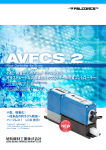
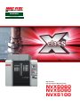
NVX5000
Machining Center
High-Precision,
High-Speed Vertical Machining Center
NVX5060
NVX5080
NVX5100
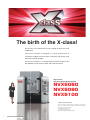
The birth of the X-class!
The X-class has evolved from our best selling N Series that sold
28,000 units.
The X-class machine is designed as a result of thousands of
customers’ feedback on the N Series, and offers high quality, high
precision and high reliability.
The X-class machine is a next-generation premium machine with
the flexibility to meet various needs and worth investment.
High-Precision,
High-Speed Vertical Machining Center
NVX5060
NVX5080
NVX5100
Compliance with safety standards
The X-class machine complies with safety standards of the respective
countries around the world. (CE marking, UL, ANSI and other standards)
CE marking: a conformance display
CE: Communauté Européenne
UL: Underwriters Laboratories Inc.
ANSI: American National Standards Institute
2
NVX5060/NVX5080/NVX5100
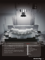
The NVX Series provides unparalleled high-speed, high-precision
CONTENTS
machining by taking comprehensive measures against thermal
04
Principal mechanisms, Original technology
displacement, including Mori Seiki’s new and original coolant
06
High precision
circulation technology and the heat-symmetrical structure that
07
Machining ability
evenly disperses heat in the spindle.
08
Environmental performance
With three machine variations, improved machine rigidity and
09
Improved convenience/Maintenance
10
Peripheral equipment
11
MAPPS Ⅳ
12
Diagrams
13
Specifications
environmental friendliness, the NVX Series offers excellent
performance in every aspect.
MAPPS: Mori Advanced Programming Production System
● Figures in inches were converted from metric measurements.
NVX5060/NVX5080/NVX5100
3
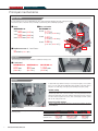
Original technology
Principal mechanisms
Principal mechanisms
Basic structure
By using slideways for all axes, the NVX5000 Series offers improved vibration damping performance and dynamic rigidity.
The machine features a wide work envelope and high-speed machining, while maintaining high rigidity.
■ Travel
■ Max. acceleration
NVX5080/40
X-axis800 mm (31.5 in.)
Y-axis 530 mm (20.9 in.)
Z-axis 510 mm (20.1 in.)
NVX5080/40
X-axis0.73 G
Z-axis
{7.15 m/s2 (23.46 ft/s2)}
Y-axis0.53 G
{5.19 m/s2 (17.03 ft/s2)}
Z-axis0.96 G
{9.41 m/s2 (30.87 ft/s2)}
X-axis
Y-axis
■ Rapid traverse rate <X, Y and Z axes>
30 m/min (1,181.1 ipm)
Variations
The X-axis travel is available in three variations to suit different workpiece sizes.
■ X-axis travel
NVX5060/40
NVX5080/40
NVX5100/40
600 mm
800 mm
1,050 mm
(41.3 in.)
(23.6 in.)
(31.5 in.)
Spindle
A spindle with a large-diameter bearing is used to improve rigidity. For the spindle
drive, we use the high-efficiency DDS (Direct Drive Spindle) motor which extracts
full power over a wide range, from high-speed machining to heavy-duty cutting.
Spindle cooling
The machine uses a spindle in which air and cooling oil pipes are arranged
symmetrically relative to the center of the spindle. This heat-symmetrical structure
minimizes thermal displacement in the spindle by dispersing heat evenly. We have
also taken measures against heat sources, with coolant piping around the spindle
and coil end cooling for the motor.
Improved spindle structure
We have enhanced the labyrinth structure to prevent any problems caused by
coolant infiltration.
Spindle variations
The NVX Series has three spindle variations to suit your
machining needs.
Standard
Max. spindle speed
Spindle drive motor
4
NVX5060/NVX5080/NVX5100
High speed
OP
High output
OP
12,000 min-1
15/11 kW
20,000 min-1
18.5/15/11 kW
8,000 min-1
30/22 kW
<10%ED/cont>
<10 min/30 min/cont>
<25%ED/cont>
(20/15 HP)
(24.7/20/15 HP)
(40/30 HP)
OP Option
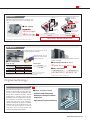
Chip disposal
Chip bucket
Hinge type+
drum filter type
Chip flush coolant and chip buckets are equipped as standard. The external chip conveyor is also available as an
option.
Spiral
conveyors
■ Tank capacity
NVX5080:
353 L (93.2 gal.)
584 L (154.2 gal.)
Chip flushing
coolant
OP
Chip bucket specifications
(standard)
(external chip conveyor specifications)
●
Y-axis protector with
front/rear washing
External chip conveyor
specifications OP
We recommend the spiral conveyor because a large amount of chips and
long chips cannot be discharged by chip flush coolant.
For details of the external chip conveyor, please refer to Page 10.
ATC, Magazine
An ATC arm with the self-return function allows
safe and high-speed tool change.
When the arm grabs a tool, the
holding lever rotates and then
the lock bar comes out.
■ Tool changing time
Chip-to-chip
Tool changing time
Adjacent <DIN>
Farthest <DIN>
<MAS>
●
●
●
Tool-to-tool
No. 40 taper
No. 40 taper
ATC standby mode OFF
ATC standby mode ON
3.49 sec.
3.49 sec.
3.45 sec.
2.98 sec.
2.96 sec.
2.98 sec.
1.3 sec.
The machine uses Mori Seiki’s original magazine, which has
a shutter as standard.
■ Tool storage capacity (No. 40 taper)
30 tools 60 tools
OP
OP
■ Max. tool diameter
Without adjacent tools
The time differences are caused by the different conditions (travel distances, etc) for each standard.
Depending on the arrangement of tools in the magazine, the chip-to-chip time may be longer.
ATC standby mode: open the ATC shutter using M code commands beforehand.
90 tools
With adjacent tools
*
150 mm (5.9 in.)
80 mm (3.1 in.)
* High speed (20,000 min-1): 125 mm (4.9 in.)
Original technology
Coolant circulation for casting parts
Mori Seiki has developed a new technology to
circulate coolant through the casting parts as a
measure against thermal displacement that
directly affects machining accuracy. Thermal
displacement is caused by various factors
including non-uniform expansion and contraction
due to difference in thickness of the casting;
uneven heat generation in the slideways;
operating environment; and changes in ambient
temperature due to season and time of day. The
coolant circulation maintains a uniform
temperature inside the casting parts, and
minimizes deformation in the machine.
OP
■ Effects of coolant circulatio
・Uniform thermal displacement
・Resistance to changes in ambient
temperature
・High-accuracy long-term machining
Coolant circulation pathway
NVX5060/NVX5080/NVX5100
5
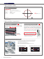
High precision
High-precision data
Roundness
90°+Y
NVX5080/40
Material <JIS>
: A5052 <outer diameter: 117 mm (4.6 in.)>
Tool
: A 16 mm (A 0.6 in.) solid carbide end mill <4 flutes>
Spindle speed
: 2,500 min-1
Feedrate
: 1,000 mm/min (39.4 ipm)
Depth of cut
: 0.1 mm (0.0039 in.)
180°
+X
−X
A5052: Aluminum
0°
Filter: 1–50
1.98 μm
(actual result)
10 μm
−Y 270°
The cutting test results indicated in this catalog are provided as examples. The results indicated in this catalog may not be obtained due to differences in cutting conditions and environmental conditions during measurement.
JIS: Japanese Industrial Standard
●
High-precision equipment
Direct scale feedback
Coolant cooling system (separate type)
OP
The absolute magnetic linear scale (full closed-loop control) made by
Magnescale is effective for high-precision positioning, and is available
as an option.
OP
Increase in the oil temperature, which is caused by heat generation
during machining or by coolant circulation, greatly affects the
dimensional accuracy of the workpieces and thermal displacement in
the machines. Please use this unit to prevent the coolant from
heating. When using oil-based coolant, the oil temperature can
become extremely high even with the standard
coolant pump, so please be sure to select this unit.
When using oil-based coolant, please be sure
to consult with your Mori Seiki representative.
Resolution
0.01 μm
While this unit is not the only way to completely control the
temperature of the coolant, it makes a major contribution to
preventing increases in the oil temperature.
●
The photo shows the NV4000 DCG
●
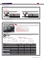
Z-axis drop prevention function ideal for blackouts
Raising the spindle slightly during blackouts prevents any contact between the tool and the workpiece caused by the spindle dropping.
Power off
※ The Z-axis drop prevention function is not available in the following situations.
1. When the feed axis servo alarm has gone off.
2. When the power supply module alarm has gone off.
3. When the communication alarm between the CNC and the amp has gone off.
Before blackout countermeasure
After blackout countermeasure (Z-axis raised)
Before
Beforeblackout
blackoutcountermeasure
countermeasure
After
Afterblackout
blackoutcountermeasure
countermeasure(Z-axis
(Z-axisraised)
raised)
TCMD
TCMD
250
250
0.24
0.24
200
200
0.20
0.20
150
150
0.16
0.16
100
100
0.12
0.12
50
50
0.08
0.08 TCMD
TCMD
Rise
Rise
00
0.04
0.04
Position
Position
-50
-50
0.00
0.00
-100
-100
-0.04
-0.04
Blackout
Blackout
-150
-150
-0.08
-0.08
0.95
0.950.955
0.9550.96
0.960.965
0.9650.97
0.970.975
0.9750.98
0.980.985
0.9850.99
0.990.995
0.995 1 1
Time
Time
(s)(s)
Position (mm)
Position (mm)
TCMD
TCMD
Position (mm)
Position (mm)
Re-machined surface
7.0
7.0
0.40
0.40
TCMD
TCMD
6.5
6.5
0.30
0.30
6.0
6.0
0.20
0.20
5.5
5.5
0.10
0.10
Position
Position
5.0
5.0
0.00
0.00
4.5
4.5
-0.10
-0.10
4.0
4.0
-0.20
-0.20
Blackout
Blackout
3.5
3.5
-0.30
-0.30
3.0
3.0
-0.40
-0.40
1.18
1.181.21.21.22
1.221.24
1.241.26
1.261.28
1.281.30
1.301.32
1.321.34
1.341.36
1.361.38
1.38
Time
Time
(s)(s)
TCMD: Torque command
Depending on how voltage drops (slowly or suddenly), it may not always be possible to detect a blackout.
●
6
NVX5060/NVX5080/NVX5100
OP Option
Machining ability
Cutting test
The NVX5000 series is suitable for a wide range of machining from heavy-duty cutting of castings to high-speed cutting of aluminum.
NVX5080/40
B 80 mm (B 3.1 in.) face mill <7 flutes>
Roughing end mill: B 20 mm (B 0.8 in.) <4 flutes>
Material <JIS>: S50C
●
Material <JIS>: S50C
Material removal rate
400 mL/min (24.4 in ./min)
Material removal rate
337 mL/min (20.6 in ./min)
Width of cut
56 mm (2.2 in.)
Width of cut
18 mm (0.7 in.)
Depth of cut
Spindle speed
Feedrate
3 mm (0.1 in.)
1,300 min-1
2,380 mm/min (93.7 ipm)
Depth of cut
Spindle speed
Feedrate
20 mm (0.8 in.)
1,300 min-1
936 mm/min (36.9 ipm)
3
3
The cutting test results indicated in this catalog are provided as examples. The results indicated in this catalog may not be obtained due to differences in cutting conditions and environmental conditions during measurement.
S50C: Carbon steel JIS: Japanese Industrial Standard
4-axis machining
Rotary table DDRT
OP
It is possible to equip the machine with the high-speed, high-accuracy DDRT SERIES rotary table which
incorporates the DDM (Direct Drive Motor). The high-efficiency machining using 4 axes and high-speed
and high-precision indexing realize process integration.
●
●
●
●
●
E quipped with DDM
Zero backlash
Achieves high-precision indexing
Offers stable machining through powerful clamping
Allows high-efficiency machining using 4 axes
Direct Drive Motor
Transmitting the drive power directly to the rotary axes without using gears eliminates backlash. Compared with conventional
worm gear systems, this dramatically improves transmission efficiency and offers high-speed feed.
■ Rotational speed of the table
Conventional
machine
DDRT-260
17 min
150 min
-1
■ Positioning accuracy
Compared with
conventional machine
Approx.
-1
Conventional
machine
9 times greater
■ Machine specifications
DDRT SERIES Compared with
conventional machine
20 sec. 5 sec.
4 times greater
DDRT-200
DDRT-260
DDRT-300
Table diameter
mm (in.)
200 (7.9)
260 (10.2)
300 (11.8)
Center height
mm (in.)
140 (5.5)
160 (6.3)
180 (7.1)
Nose hole diameter
mm (in.)
65 (2.6) H7
75 (3.0) H7
95 (3.7) H7
Through hole diameter
mm (in.)
50 (2.0)
50 (2.0)
50 (2.0)
Air
Air
Air
60/160 (44.3 /118.0)
105/280 (77.4 /206.5)
180/410 (132.8 /302.4)
Clamp system
Drive torque <cont/max.>
N·m (ft·lbf)
Rotational speed of the table
Repeatability
Positioning accuracy
min-1
250
150
120
Unclamped
sec.
2
2
2
Clamped
sec.
5
5
5
Unclamped
sec.
5
5
5
200 (440)
Mass of machine <rotary table>
kg (lb.)
120 (264)
155 (341)
Maximum work inertia <vertical>
kg·m2
0.45
0.678
1.6
kg (lb.)
100 (220)
150 (330)
175 (385)
Table loading capacity
Vertical load
Maximum thrust load
applicable on the table
Clamp torque
N·m (ft·lbf), F×L
800 (590.0)
1,000 (737.6)
1,000 (737.6)
Moment load
N·m (ft·lbf), F×L
1,500 (1,106.3)
3,000 (2,212.7)
4,000 (2,950.2)
NVX5060/NVX5080/NVX5100
7
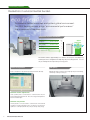
Environmental performance
Reduction in environmental burden
eco friendly
To conserve limited resources and protect global environment.
The NVX Series pursues a high “environmental performance”
that is required of machine tools.
Comparison of power consumption
Change in motor
configuration
☞
▲ 11.95
Power-saving function
(during standby)
☞
▲ 0.18
LED lighting
☞
kVA
kVA
▲ 5.5 W
Approx.
Reduced by
(kVA)
50
40
41.1 kVA
30
35 %
26.9 kVA
20
As a result...
10
0
Previous model
NVX5000
SERIES
The machine achieves approximately 35% reduction in total power consumption by
reviewing the motor configuration and improving the power-saving function. It is not
only eco-friendly, but also helps reduce your energy costs.
削減!
Power-saving function
Power consumption is reduced while operating the machine efficiently.
Automatic machine light function
If the operation panel is not touched for a certain amount of time, the
interior light automatically turns off. This saves energy and lengthens the
life of the machine lights.
Automatic sleep function
If the keyboard is not touched after a certain amount of time and NC
operation is not being performed, power is cut off to the servo motor, the
spindle, the coolant pump and the chip conveyor, thereby saving energy.
8
NVX5060/NVX5080/NVX5100
LED lighting
LED with high luminous efficiency offers a high light output at a low wattage,
contributing to reducing electricity use.
OP Option
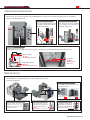
Improved convenience/Maintenance
Improved convenience
With an easy-to-access table and openable ceiling, the NVX5000 Series is designed to offer superior operability and ease of setup that are
required of vertical machining centers.
Swivel-type operation panel
Loading and unloading with a crane
The operation panel which can swivel
from 0 degree to 90 degrees improves
operability and visibility.
The ceiling part also opens, allowing
easy loading and unloading of
workpieces using a crane.
90°
Accessibility
With excellent access to the table and a wide door opening, setup operations such as fixture adjustment can be done smoothly.
Distance from table
243 mm (9.6 in.)
Door opening
920
mm
(36.2 in.)
Height of table top surface
900 mm (35.4 in.)
Maintenance
The NVX5000 Series is designed with features for ease of maintenance to increase
the machine operating rate.
Improved magazine design
A new magazine has a door and steps for easier
operation and maintenance.
Magazine step OP
Centralized layout of devices
Devices which need to be
inspected ever y day are
gathered together at the
side of the machine.
Slimmer electrical cabinet
A slim electrical cabinet closes the
proximity between you and the insides
of the machine during maintenance.
320 mm (12.6 in.)
<including doors>
magazine door OP
Replacement of spindle unit
By changing the spindle unit to a
cartridge, which even includes the
rear bearings, we have dramatically
reduced replacement time.
Spindle unit
NVX5060/NVX5080/NVX5100
9
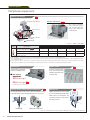
Peripheral equipment
Peripheral equipment
External chip conveyor
OP
Hinge type+drum filter type
Hinge type+drum filter type
Recommended
This conveyor can handle
various types and length of
chips. The built-in drum filter
helps to reduce frequency of
cleaning the tank.
Spiral conveyors
Y-axis protector with front/
rear washing
Chip transport route
Frequency
of
cleaning
Low
High
Specifications
Long
Steel
◎: Ideal ○: Suitable ×: Not suitable
Workpiece material and chip size
Cast iron
Aluminum/non-ferrous metal
Short
Short
Long
Short
◎
◎
○
◎
◎
Magnet scraper type
×
○
◎
×
×
Hinge type
○
×
×
○
×
Hinge type+drum filter type
Recommended
*
* Short chips may escape into the tank.
Chip size guidelines Short: chips 50 mm (2.0 in.) or less in length, bundles of chips A 40 mm (A 1.6 in.) or less Long: bigger than the above
The options table below the general options when using coolant. Changes may be necessary if you are not using coolant, or depending on the amount of coolant, compatibility with machines,
or the specifications required.
● Please select a chip conveyor to suit the shape of your chips. When using special or difficult-to-cut material (chip hardness HRC45 or higher), please consult with your Mori Seiki representative.
●
●
●
Chip conveyors are available in various types for handling chips of different shape and material. For details, please consult with your Mori Seiki representative.
Coolant tank
Shower coolant
A high capacity coolant tank
comes as a standard feature.
OP
As well as preventing chips
from scattering during
machining, this allows them
to fall smoothly.
■ Tank capacity
NVX5080:
353 L (93.2 gal.)
584 L (154.2 gal.)
OP
(external chip conveyor specifications)
Through-spindle coolant system (separate type)
OP
The through-spindle coolant system effectively eliminates chips,
cooling the machine point, and lengthening the lives of your tools.
Center through
NVX5060/NVX5080/NVX5100
Supplies air and oil mist to the cutting
tip. An environmentally friendly device
which reduces oil consumption. We
recommend using this unit together
with a mist collector.
OP
Misting
device
High-pressure coolant system
●
10
Semi dry unit
The colors and configurations shown in the photographs or illustrations may differ from those of the actual product.
MAPPS Ⅳ
OP Option
A New High-Performance Operating System
for Machining Centers
A new high-performance operating system that pursues ease of use, and combines
the best hardware in the industry with the advanced application/network systems.
▶ Outstanding operability thanks to upgraded hardware
▶ Enhanced functionality by using CAM software (option)
▶ New functions for easier setup and maintenance
▶ Machine interior and exterior can be monitored on the screen
(option)
Outstanding operability
Vertical soft-keys
The vertical soft-keys can be used as option buttons or shortcut keys
to which you can assign your desired screens and functions, allowing
you to quickly display the screen you want.
Keyboard
●
10.4-inch operation panel
A PC-type keyboard is used as standard, making key input easy. A
keyboard with a conventional key layout is also available as an option.
Faster creation of programs
Advanced hardware
Reduction of drawing time
Shorter drawing time was achieved thanks to increased CPU performance.
MAPPS Ⅲ
68 sec.
MAPPS Ⅳ 45 sec.
Approx.
Reduced by
33 %
User area
Interface
⃝ CAM software will be ready to use once your machine is installed
1 GB
⃝ Cost for introducing CAM software can be saved
1 GB
・USB 2.0 3 ports
(Screen side: 1, Back of operation panel: 2)
・LAN 2 ports (1000BASE-T)
Right 10 keys
⃝ ESPRIT® data can be modified on the machine
(through Remote Desktop connection*)
⃝ The software can be installed on multiple PCs on the network
(It cannot be simultaneously started up on more than one PC)
・Memory card slot
Soft-keys
OP
⃝ Postprocessor as standard
Main specifications
Main memory
CAM software
ESPRIT® allows you to create complex 3D programming with high-added value.
By just installing the software on your PC with connection to LAN, you will be
able to use it. (Once the software is started on the computer, it can be used for
up to 7 days without LAN connection.)
Bottom 12 keys
⃝ 2-year warranty support (including free update)
* Applicable Operating Systems: Windows Vista Business / Ultimate, Windows 7 Professional / Ultimate
● A PC is required to use ESPRIT®. Please prepare PCs by yourself.
Improved ease of setup and maintenance
MAPPS Ⅳ is packed with new functions for easier setup and maintenance,
including the File Display and Memo function that displays operating
instructions and manuals on the screen and the Alarm help function that
provides instructions when alarms occur.
File display and Memo function
Improved work efficiency
MAPPS Camera
OP
Please contact Mori Seiki
Images taken by cameras installed inside/outside the machine can be displayed
on the programming screen. This function is useful for maintenance.
Alarm help function
Possible camera
installation points
・Inside machine
(to check machining)
・Chip bucket
(to check chip accumulation)
・Tool magazine
(to check cutting tools)
・Other points requested by
customers
MAPPS: Mori Advanced Programming Production System
●
●
The photo shown may differ from actual machine.
Information about the screen is current as of October 2010.
NVX5060/NVX5080/NVX5100
11
OP Option
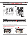
Diagrams
Installation diagrams(NVX5060, NVX5080, NVX5100)
Front view
Plan view
H
D
W1
W2
Q55272A04
mm(in.)
Width
W2
<Chip bucket specifications>
Hinge type+drum filter type OP
Depth
D
Machine only/Including chip conveyor
NVX5060
2,000 (78.7)
3,071 (120.9)
3,670 (144.5)/3,718 (146.4)
2,597 (102.2)
NVX5080
2,180 (85.8)
3,251 (128.0)
3,670 (144.5)/3,718 (146.4)
2,597 (102.2)
NVX5100
2,740 (107.9)
3,811 (150.0)
3,670 (144.5)/3,718 (146.4)
2,597 (102.2)
Machine type
W1
Height
H
Spindle speed torque/output diagrams
NVX5060/40, NVX5080/40, NVX5100/40
【 Standard 】
【 High output
Torque (N・m)
T=55.1 N・m (40.6 ft・lbf) <cont>
7.5 kW
<cont>
10
300
200
11.3
10
8.25
11 kW <cont>
T=304 N・m (224.2 ft・lbf) <15%ED>
100 T=147 N・m (108.4 ft・lbf)
<cont>
10
2448
Winding
switchover
point
1
10
100
1000 1300
Spindle speed (min-1)
12
600
30
Torque (N・m)
15 kW <10%ED>
■ Spindle
drive motor: 30/22 kW (40/30 HP) <25%ED/cont>
Output (kW)
T=110 N・m (81.1 ft・lbf) <10%ED>
NVX5060/NVX5080/NVX5100
】
■ Max. spindle speed: 8,000 min-1
■ Spindle drive motor: 15/11 kW (20/15 HP) <10%ED/cont>
100
OP
1
9000 12000
3500
10000
1.0
10
Q43498A01
30 kW <25%ED>
28
22 kW 20
<cont> 10
122 N・m
(90.0 ft・lbf)
T=143 N・m (105.5 ft・lbf)
<25%ED>
1200
100
50
690
1000
Spindle speed (min-1)
T=84 N・m
(62.0 ft・lbf)
<cont>
1466
Winding
switchover
point
7500
2500
1.0
Output (kW)
■ Max. spindle speed: 12,000 min
-1
0.1
8000
Q43629A01
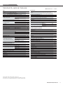
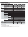
Specifications
Standard & optional features
● : Standard features ○: Options
主軸
Chip disposal
12,000min-1: 15/11 kW (20/15 HP) <10%ED/cont>
20,000 min-1: 18.5/15/11kW (24.7/20/15 HP)
<10 min/30min/cont> {high speed}
8,000 min-1: 30/22 kW (40/30 HP) <25%ED/cont> {high output}
BT40
Dual contact
Fan cooler type
Spindle cooling system
Inverter-controlled oil cooler
(separate type)
●
○
○
○
●
Tool storage capacity
ATC shutter
Magazine door
Sub table
Measurement
○
○
●
○
●
Through-spindle coolant system
(separate type) center through
●
Operation support device/function
T-slot
Solid
T-slot
●
Auto power off
Automatic door
○
Improved accuracy
○
Direct scale feedback for X, Y, Z-axis
Coolant circulation for casting parts
●
●
●
○
(R)
○
(M)
(R)
○
○
●
○
○
○
●
Safety features
●
Full cover
Door interlock system <incl. mechanical lock>:
front door/setup station door (for APC)
●
●
1.5 MPa (217.5 psi) <water-soluble>
7.0 MPa (1,015 psi)
Interface {1.5 MPa (217.5 psi)
<water-soluble>}
○
Interface <7.0 MPa (1,015 psi)>
○
Door interlock system: electrical cabinet door
Low air pressure detecting switch
Residual pressure exhaust valve
Interface <7.0 MPa (1,015 psi)>
○
Others
Through-spindle air specifications (only for air)
Coolant cooling system (separate type) for standard coolant system
125 mm (4.9 in.)
Mist collector interface (duct only)
150 mm (5.9 in.)
200 mm (7.9 in.)
Mist collector (HVS-220), including stand
Shower coolant
Additional coolant system for tool tip
Oil-hole drill coolant system
Oil skimmer
Semi dry unit (Tanaka Import)
Oil shot system
Oil mist system
○
T
he specifications vary depending on the manufacturers.
(R): Made by RENISHAW (M): Made by METROL
●
Coolant system
Chip flushing coolant
○
○
Optical type touch sensor
OMP60
Touch sensor
In-machine measuring system (table)
Touch sensor
●
○
In-machine measuring system (spindle)
BT40
MORI SEIKI 90° type
Coolant
Through-spindle coolant system
(unit on coolant tank) center through
Coolant gun for machining side
Chip conveyor (internal, spiral type)+Chip conveyor interface (external)
●
Table
Table
regularly used, air supply of more than
300 L/min (79.2 gpm) is separately required>
○
ATC
Type of tool shank
Type of retention knob
Tool tip <when the tool tip air blow is
Chip conveyor (internal, spiral type)+
Chip conveyor (external, hinge type+drum filter type)
Chip conveyor (internal, spiral type)
Chip bucket
Tool magazine
30 tools
60 tools
90 tools
Air blow
○
○
○
○
○
○
○
○
○
○
○
○
○
○
○
●
●
●
Built-in worklight (LED)
T-nuts for table slots
Leveling block
Hand tools
Signal tower 3 layers
Raised column
200 mm (7.9 in.)
Angle head
Dry anchor
Index table interface (M signal output from terminal block)
SMC Refrigerating type air dryer
Manual pulse generator (separate type)
Machine covers disassembled for export shipment
Additional in-machine light
Additional axis interface
Additional axis DDRT
●
●
●
●
○
○
○
○
○
○
○
○
○
○
○
The information in this catalog is valid as of October 2010.
Specifications, accessories, safety device and function are available upon request.
Some options are not available in particular regions. For details contact Mori Seiki.
NVX5060/NVX5080/NVX5100
13
Specifications
Numerical control unit specifications (MSX-853 Ⅳ)
Controlled axes
Feed functions
Controlled axes
X, Y, Z, MG
Simultaneously controlled axes 4 axes
Least input increment
0.001 mm (0.0001 in.)
Max. command value
Inch/metric conversion
Machine lock
Overtravel
Door interlock
Stored stroke check 1, 2
Load monitor function C
Programming resolution
multiplied by 1/10
●
●
●
±99,999.999 mm
(9,999.9999 in.)
●
G20/G21
●
●
●
●
●
Soft key type
3 axes (X, Y, Z)
●
○
Operation
DNC operation by the memory card
Sequence number comparison and stop
Program restart
Dry run
Single block
0−5,000 mm/min
Jog feed
(0−197.0 ipm) <20 steps>
Manual reference position return
Pulse handle feed
Manual pulse generator:
1 unit ×1, ×10, ×100
(per pulse)
Manual handle feed
×1, ×10, ×100
Z-axis neglect
Manual handle interruption
1 GB Program storage area
(for card DNC operation
function, for data backup)
<MAPPS>
Files up to 10 MB in size
can be edited
Synchronous peck tapping
○
○
○
●
●
●
Helical interpolation
Reference position return
Reference position return
check
Return from reference
position
●
Rapid traverse override
F0/1/10/25/100%
Feed per minute
Tangential speed constant control
Cutting feedrate clamp
Automatic acceleration/
deceleration
○
●
●
●
●
●
●
●
G28
●
G27
●
●
●
○
○
○
○
○
○
Linear type (rapid traverse)/
Exponential function type
(cutting feed)
Feedrate override
0−200% (10% increments)
Override cancel
Linear acceleration/deceleration after cutting feed interpolation
High accuracy control (look-ahead control)
Inverse time feed
High-speed and high accuracy controlⅠ(AI contour control)
High-speed and high accuracy control Ⅱ
(high-precision contour control)
●
●
●
●
●
●
○
○
○
●
±8 digits
●
4 digits (For an 8 digit
program number, a sequence
change is necessary)
●
G90/G91
●
Decimal point programming
or electronic calculator type
Decimal point programming
decimal point programming
can be set using parameters
Diameter/radius programming
Plane selection
G17, G18, G19
Rotary axis designation
Rotary axis roll-over
Coordinate system setting G92
Automatic coordinate system setting
Workpiece coordinate system G52−59
Programmable data input
G10
Optional chamfering/corner R
Sub-program call
Up to 8 nestings
Custom macro
Hole machining canned cycle G80−89
Programmable mirror image
Addition of optional block skip Soft key type (2−9)
Polar coordinate command
Workpiece coordinate system preset
Custom macro common
variables <in total>
300 variables
(#100 to #199, #500 to #699)
600 variables
(#100 to #199, #500 to #999)
Interruption type custom macro
Scaling
G50/G51
Coordinate system rotation G68/G69
Additional workpiece
48 sets
coordinate systems
MORI-POST advanced mode <MAPPS>
DXF import function <MAPPS>
Islands, open pockets <MAPPS>
Text engraving function <MAPPS>
●
●
●
●
●
●
●
●
●
○
●
●
●
●
○
○
○
○
○
○
○
○
○
○
○
○
○
Miscellaneous function/Spindle speed function
Miscellaneous function
(M function)
Auxiliary function lock
Spindle speed function
(S function)
Spindle speed override
Spindle orientation
Synchronous tapping
●
14
The information in this catalog is valid as of September 2010.
NVX5060/NVX5080/NVX5100
4-digit M code
8-digit T code
●
Number of tool offsets
200 sets
(diameter+length=1 set,
number of offsets indicates
that diameter and length
are displayed separately)
●
●
●
●
●
5-digit S code
●
50−150% (10% increments)
●
●
●
●: Standard ○: Options
Tool function (T function)
●
Program input
Absolute/incremental
programming
Optional 2 axes and other
1 axis
2nd reference position return G30 (used for ATC/APC)
Computer link B
Cylindrical interpolation
G7.1
Installation of high-speed skip terminal
Spiral/conical interpolation
Threading, synchronous cutting/Feed per revolution
Tool spindle Cs control
(Cs contour control+normal direction control)
1−5,000 mm/min
(0.01−196.9 ipm)
●
●
G29
Cutting feedrate
Program number
●
G61
G63
G64
G09
●
●
○
G00
Max. 60,000 mm/min
(2,362.2 ipm)
Optional block skip
Max. command value
Interpolation functions
Nano interpolation
Positioning
Single direction positioning
Exact stop mode
Tapping mode
Cutting mode
Exact stop
Rapid traverse rate
●
●
Tool offset
Tool offset memory C
D/H code, geometry/wear
Tool length offset
G43, G44, G49
Cutter radius offset
G40−G42
Tool length measurement
Tool position offset
G45−G48
MAPPS tool management system
●
●
●
○
○
●
MAPPS tool management system+
Tool IC (MAPPS software only)*
○
MAPPS tool management system+
Tool ID (MAPPS software only)*
○
*Separate consultation is required if hardware and software
are customized.
Mechanical accuracy compensation
Backlash compensation
±9,999.99 pulses
Rapid traverse/cutting feed backlash compensation
Stored pitch error compensation
Interpolation type pitch error compensation
●
●
●
○
Editing
125 kB/200 programs
Part program storage length 230 kB/400 programs
<in total>/
500 kB/1,000 programs
Registerable programs
1,000 kB/1,000 programs
<in total>
2,000 kB/1,000 programs
2,560
m (8,400 ft)
Part program storage length
<1 MB>+1,000 programs
<in total>+
Registerable programs
5,120 m (16,800 ft)
<in total>
<2 MB>+1,000 programs
Part program edit
Deletion, insertion, and
alteration
Program protect
Background editing
Undo/Redo function <MAPPS>
Line number display <MAPPS>
●
○
○
○
○
○
○
●
●
●
●
●
Operation and display
Status display
Clock function
Current position display
Program comment display 48 characters
Parameter setting display
Alarm display
Alarm history display
Operator’s message history display
Operation history display
Running time/Parts count display
Actual cutting feedrate display
Operating monitor screen
Load meter display etc.
Help function
Self-diagnosis
Includes alarm display,
I/O signal diagnosis and
ladder diagram
Operation panel:
10.4-inch TFT color LCD
display section
Multi-counter display <MAPPS>
●
●
●
●
●
●
●
●
●
●
●
●
●
●
●
○
I/O functions and units
Memory card input/output
●
USB
I/O interface
RS-232-C
Data server (excluding memory card)
Fast data server
100BASE-TX
Memory card for data server
Data server+memory card for data server
CF card (2 GB/512 MB)
Memory card for MAPPS
+ATA card
●
○
○
○
○
○
○
I95042A01
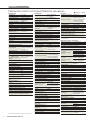
Specifications
Machine specifications
Item
Travel
Table
Spindle
Feedrate
ATC
X-axis travel <longitudinal movement of table> mm (in.)
Y-axis travel <cross movement of saddle> mm (in.)
Z-axis travel <vertical movement of spindle head> mm (in.)
Distance from table surface to spindle gauge plane mm (in.)
Distance from table surface to floor surface
mm (in.)
Working surface
mm (in.)
Table loading capacity
kg (lb.)
Table surface configuration <T slots width×pitch×No. of T slots>
Max. spindle speed
min-1
Number of spindle speed ranges
Type of spindle taper hole
Spindle bearing inner diameter
mm (in.)
Rapid traverse rate
mm/min (ipm)
Feedrate
mm/min (ipm)
Jog feedrate
mm/min (ipm)
Type of tool shank
Type of retention knob
Tool storage capacity
With adjacent tools
mm (in.)
Max. tool diameter
Without adjacent tools
mm (in.)
Max. tool length mm (in.)
Max. tool mass
kg (lb.)
Method of tool selection
s
Tool-to-tool
Tool changing time
The time differences are caused by
the different conditions (travel
distances, etc) for each standard.
●
Chip-to-chip
(ATC standby
mode OFF)
Depending on the arrangement of
tools in the magazine, the chip-to- Chip-to-chip
chip time may be longer.
●
(ATC standby mode)
Spindle drive motor
Motor
Power sources
<standard>
Tank capacity
Machine size
Feed motor
Coolant pump motor <50/60 Hz>
Electrical power supply <cont>
Compressed air supply
Coolant tank capacity
Machine height
Floor space <width×depth>
Mass of machine
12,000 min-1
[8,000 min-1]
[20,000 min-1]
<DIN>
s
<MAS>
s
<DIN>
s
<MAS>
s
kW (HP)
kW (HP)
kW (HP)
kW (HP)
kW (HP)
I94293EA01 kVA
MPa (psi), L/min (gpm)
L (gal.)
mm (in.)
mm (in.)
kg (lb.)
N V X 5060/ 40
N V X 5080/ 40
N V X 5100/ 40
600 (23.6)
800 (31.5)
1,050 (41.3)
530 (20.9)
510 (20.1)
150ー660 (5.9ー26.0)
900 (35.4)
900×600 (35.4×23.6)
1,100×600 (43.3×23.6)
1,350×600 (53.1×23.6)
800 (1,760)
1,000 (2,200)
1,200 (2,640)
18 mm×100 mm×6 (0.7 in.×3.9 in.×6)
12,000[8,000]
[20,000]
1
No. 40
80 (3.1) <12,000 min-1 specifications, 8,000 min-1 specifications>
X, Y, Z: 30,000 (1,181.1)
1ー30,000 (0.01ー1,181.1) <when using look-ahead control>
0ー5,000 (0ー197.0) <20 steps>
BT40[CAT40]
[DIN40]
[HSK-63A]
MORI SEIKI 90° type[45°(MAS-Ⅰ)
[60°
] (MAS-Ⅱ)
[
]DIN]
[HSK]
30[60]
[90]
80 (3.1)
150 (5.9)[125 (4.9) <high speed>]
300 (11.8)
8 (17.6)
[12 (26.4)]
Technical memory random
1.3
Adjacent:3.49
Farthest:3.49
3.45
Adjacent: 2.98
Farthest: 2.96
2.98
(ATC standby mode: Open the ATC shutter using M code commands beforehand.)
15/11(20/15) <10%ED/cont>
30/22 (40/30) <25%ED/cont>
18.5/15/11 (24.7/20/15) <10 min/30 min/cont>
X, Y: 3.0 (4) Z: 4.5 (6)
0.73×2/1.21×2 (1.0×2/1.6×2)
27.5
0.5 (72.5), 200 (52.8) <ANR>
320 (84.5) [535 (141.2)*]
353 (93.2) [584 (154.2)*]
443 (117.0) [734 (193.8)*]
2,597 (102.2)
2,000×3,670 (78.7×144.5)
2,180×3,670 (85.8×144.5)
2,740×3,670 (107.9×144.5)
[3,071×3,718 (120.9×146.4)*] [3,251×3,718 (128.0×146.4)*] [3,811×3,718 (150.0×146.4)*]
6,000 (13,200)
6,350 (13,970)
7,000 (15,400)
[ ]Option
*External chip conveyor specifications
Max. spindle speed: depending on restrictions imposed by the workpiece clamping device, fixture and tool used, it may not be possible to rotate at the maximum spindle speed.
Please use a flange tool when cutting at 15,000 min-1 or higher.
● ANR: ANR refers to a standard atmospheric state; i. e., temperature at 20 °C (68 ˚F), absolute pressure at 101.3 kPa (14.7 psi) and relative humidity at 65%.
● Power sources, machine size: the actual values may differ from those specified in the catalogue, depending on the optional features and peripheral equipment.
● Compressed air supply: please be sure to supply clean compressed air <air pressure: 0.7 MPa (101.5 psi), pressure dew point: 10 °C (50 °F) or below>.
● A criterion capacity to select a compressor is 90 L/min (23.8 gpm) per 0.75 kW (1 HP).
However, this figure may differ depending on the type of compressors and options attached. For details, please check the compressor specifications.
●
●
NVX5060/NVX5080/NVX5100
15
2-year warranty, twice the peace of mind.
●
Subject to limitations, Mori Seiki machines ordered after April 1, 2007
now have a 2-year warranty.
Please contact your sales representative for details.
For machines delivered outside of Japan, parts relating to machine breakdown will be guaranteed free for 2 years from the date of installation, and labor costs to repair will be free for 1 year.
<Precautions for Machine Relocation>
EXPORTATION: All contracts are subject to export permit by the Government of Japan. Customer shall comply with the laws and regulations of the exporting country governing the exportation or re-exportation
of the Equipment, including but not limited to the Export Administration Regulations. The Equipment is subject to export restrictions imposed by Japan and other exporting countries and the Customer will not
export or permit the export of the Equipment anywhere outside the exporting country without proper government authorization. To prevent the illegal diversion of the Equipment to individuals or nations that
threaten international security, it may include a “Relocation Machine Security Function” that automatically disables the Equipment if it is moved following installation. If the Equipment is so-disabled, it can only
be re-enabled by contacting Mori Seiki or its distributor representative. Mori Seiki and its distributor representative may refuse to re-enable the Equipment if it determines that doing so would be an unauthorized
export of technology or otherwise violates applicable export restrictions. Mori Seiki and its distributor representative shall have no obligation to re-enable such Equipment. Mori Seiki and its distributor
representative shall have no liability (including for lost profits or business interruption or under the limited service warranty included herein) as a result of the Equipment being disabled.
DCG, DDM, BMT and ORC are trademarks or registered trademarks of Mori Seiki Co., Ltd. in Japan, the USA and other countries.
If you have any questions regarding the content, contact your nearest Mori Seiki distributor or Technical Center.
The information in this catalog is valid as of October 2010. Designs and specifications are subject to changes without notice.
● Mori Seiki is not responsible for differences between the information in the catalog and the actual machine.
●
●
●
Nagoya Head Office
2-35-16 Meieki, Nakamura-ku, Nagoya City, Aichi 450-0002, Japan
Phone: (052) 587-1811
Tokyo Branch
Nara Campus No. 1 Plant
Nara Campus No. 2 Plant
Iga Campus
Chiba Campus
18th floor, Shinagawa Intercity Tower A, 2-15-1 Konan Minato-ku, Tokyo 108-6018, Japan
362 Idono-cho, Yamato-Koriyama City, Nara 639-1183, Japan
106 Kita-Koriyama-cho, Yamato-Koriyama City, Nara 639-1160, Japan
201 Midai, Iga City, Mie 519-1414, Japan
488-19 Suzumi-cho, Funabashi City, Chiba 274-0052, Japan
Phone: (03) 5460-3570
Phone: (0743) 53-1121
Phone: (0743) 53-1125
Phone: (0595) 45-4151
Phone: (047) 410-8800
NVX5000-EA01-1D
D.1010.CDT.0000
Created in Japan