1
Configuring User Authentication
This chapter provides the following information about configuring and monitoring user authentication on Enterasys® N‐Series, S‐Series®, and K‐Series modular switches, A‐Series, B‐Series, C‐Series stackable fixed switches, and D‐Series, G‐Series, and I‐Series standalone fixed switches.
Note: Through out this document:
• Use of the term “modular switch” indicates that the information is valid for the N-Series, S-Series,
and K-Series platforms.
• Use of the term “stackable fixed switch” indicates that the information is valid for the A-Series,
B-Series, and C-Series platforms.
• Use of the term “standalone fixed switch” indicates that the information is valid for the D-Series,
G-Series, and I-Series platforms.
For information about...
Refer to page...
What is User Authentication?
1
Why Would I Use It in My Network?
2
How Can I Implement User Authentication?
2
Authentication Overview
2
Configuring Authentication
14
Authentication Configuration Example
29
Terms and Definitions
34
What is User Authentication?
Authentication is the ability of a network access server, with a database of valid users and devices, to acquire and verify the appropriate credentials of a user or device (supplicant) attempting to gain access to the network. Enterasys authentication uses the RADIUS protocol to control access to switch ports from an authentication server and to manage the message exchange between the authenticating device and the server. Both MultiAuth and Multi‐user authentication are supported. MultiAuth is the ability to configure multiple authentication modes for a user and apply the authentication mode with the highest precedence. Multi‐user is the ability to appropriately authenticate multiple supplicants on a single link and provision network resources, based upon an appropriate policy for each supplicant. The Enterasys switch products support the following five authentication methods:
April 15, 2011
•
IEEE 802.1x
•
MAC‐based Authentication (MAC)
•
Port Web Authentication (PWA)
Page 1 of 36
Why Would I Use It in My Network?
•
Convergence End Point (CEP)
•
RADIUS Snooping
Note: The RADIUS Snooping user authentication feature is detailed in the Configuring RADIUS
Snooping feature guide. The RADIUS Snooping feature guide can be found at:
https://extranet.enterasys.com/downloads.
Enterasys switch products support the configuration of up to three simultaneous authentication methods per user, with a single authentication method applied based upon MultiAuth authentication precedence.
Why Would I Use It in My Network?
Network resources represent a major capital investment for your organization and can be vulnerable to both undesired resource usage and malicious intent from outside users. Authentication provides you with a user validation function which assures that the supplicant requesting access has the right to do so and is a known entity. To the degree a supplicant is not a known entity, access can be denied or granted on a limited basis. The ability of authentication to both validate a user’s identity and define the resources available to the user assures that valuable network resources are being used for the purposes intended by the network administrator.
How Can I Implement User Authentication?
Take the following steps to implement user authentication:
•
Determine the types of devices to be authenticated.
•
Determine the correct authentication type for each device.
•
Determine an appropriate policy best suited for the use of that device on your network.
•
Configure RADIUS user accounts on the authentication server for each device.
•
Configure user authentication.
Authentication Overview
Note: See the Enterasys Matrix X Core Router Configuration Guide for X-Series switch
authentication configuration information.
April 15, 2011
For information about...
Refer to page...
IEEE 802.1x Using EAP
3
MAC-Based Authentication (MAC)
3
Port Web Authentication (PWA)
3
Convergence End Point (CEP)
4
Multi-User And MultiAuth Authentication
4
Remote Authentication Dial-In Service (RADIUS)
8
Page 2 of 36
Authentication Overview
IEEE 802.1x Using EAP
The IEEE 802.1x port‐based access control standard allows you to authenticate and authorize user access to the network at the port level. Access to the switch ports is centrally controlled from an authentication server using RADIUS. The Extensible Authentication Protocol (EAP), defined in RFC 3748, provides the means for communicating the authentication information. There are three supported types of EAP: •
MD5 – EAP‐MD5 is a challenge‐handshake protocol over EAP that authenticates the user with a normal username and password.
•
TLS – EAP‐TLS provides a transport layer security based upon the presentation and acceptance of digital certificates between the supplicant and the authentication server. •
Protected – Protected Extensible Authentication Protocol (PEAP) optionally authenticates the authentication server to the client using an X‐509 certificate using a TLS tunnel, after which the client authentication credentials are exchanged.
All Enterasys platforms support IEEE 802.1x, which protects against unauthorized access to a network, DoS attacks, theft of services and defacement of corporate web pages. 802.1x configuration consists of setting port, global 802.1x parameters, and RADIUS parameters on the switches to point the switch to the authentication server. The Filter‐ID RADIUS attribute can be configured on the authentication server to direct dynamic policy assignment on the switch to the 802.1x authenticating end system.
MAC-Based Authentication (MAC)
MAC‐based authentication (MAC) authenticates a device using the source MAC address of received packets. The authenticator sends the authentication server a source MAC address as the user name and a password that you configure on the switch. If the authentication server receives valid credentials from the switch, RADIUS returns an Accept message to the switch. MAC authentication enables switches to authenticate end systems, such as printers and camcorder devices that do not support 802.1x or web authentication. Since MAC‐based authentication authenticates the device, not the user, and is subject to MAC address spoofing attacks, it should not be considered a secure authentication method. However, it does provide a level of authentication for a device where otherwise none would be possible.
The modular switch, stackable fixed switch, and standalone fixed switch devices support MAC‐based authentication.
Port Web Authentication (PWA)
Port Web Authentication (PWA) authenticates a user by utilizing a web browser for the login process to authenticate to the network. To log in using PWA, a user opens the web browser requesting a URL that either directly accesses the PWA login page or is automatically redirected to the login page. At the PWA login page, the user enters a login username and password. On the switch, either the Challenge Handshake Authentication Protocol (CHAP) or the Password Authentication Protocol (PAP) verifies the username and password credentials provided to the authentication server. If the credentials are validated, the authentication server returns a RADIUS Accept message, optionally containing Filter‐ID or tunnel attributes, to the switch.
PAP uses an unencrypted password. CHAP uses the password to generate a digest that is transmitted to the authentication server. If RADIUS determines that the digest matches the digest generated on the authentication server, access is granted. The acceptance message back to the April 15, 2011
Page 3 of 36
Authentication Overview
switch can contain any Filter‐ID attribute configured on the authentication server, allowing policy to be applied for the authenticating user.
PWA enhanced mode is supported. PWA enhanced mode allows a user on an un‐authenticated PWA port to enter any URL into the browser and be presented the PWA login page on their initial web access. When enhanced mode is disabled, a user must enter the correct URL to access login. The modular switches, B‐Series and C‐Series stackable fixed switches, and the standalone fixed switches support PWA. Note: For stackable fixed switches and standalone fixed switches:
• One user per PWA-configured port can be authenticated
• PWA authentication supports RFC 3580 VLAN authorization on B3, B5, C3, C5,and G3 devices
Convergence End Point (CEP)
CEP detects an IP telephony or video device on a port and dynamically applies a specific policy to the port. The switch detects a convergence end point by inspecting received packets for specific traffic attributes. CEP does not require a RADIUS configuration. The CEP implementation supports the following detection methods:
•
Cisco Phone Detection ‐ the firmware parses a Cisco Discovery Protocol (CDP) packet to identify the phone type. If it was sent by an IP phone, the firmware uses the phone type. A response is sent back to the phone, verifying authentication.
•
Siemens HiPath Phone Detection ‐ TCP/UPD port number snooping is used. Port 4060 is the default port for communication.
•
H.323 Phone Detection ‐ TCP/UDP port number snooping and reserved IP address snooping are used. Ports 1718 ‐ 1720 and IP address 224.0.1.41 are the default values. •
Session Initiation Protocol (SIP) Phone Detection ‐ TCP/UDP port number snooping and reserved IP address snooping are used. Port 5060 and IP address 224.0.1.75 are the default values.
The modular switches support CEP.
Multi-User And MultiAuth Authentication
This section will discuss multi‐user and MultiAuth authentication. Multi‐user and MultiAuth are separate concepts. The primary difference between the two is as follows: April 15, 2011
•
Multi‐user authentication refers to the ability to authenticate multiple users and devices on the same port, with each user or device being provided the appropriate level of network resources based upon policy. •
MultiAuth authentication refers to the ability of a single or multiple user(s), device(s), or port(s) to successfully authenticate using multiple authentication methods at the same time, such as 802.1x, PWA, and MAC, with precedence determining which authentication method is actually applied to that user, device, or port.
Page 4 of 36
Authentication Overview
Multi-User Authentication
Multi‐user authentication provides for the per‐user or per‐device provisioning of network resources when authenticating. It supports the ability to receive from the authentication server:
•
A policy traffic profile, based on the user account’s RADIUS Filter‐ID configuration
•
A base VLAN‐ID, based on the RFC 3580 tunnel attributes configuration, also known as dynamic VLAN assignment
When a single supplicant connected to an access layer port authenticates, a policy profile can be dynamically applied to all traffic on the port. When multi‐user authentication is not implemented, and more than one supplicant is connected to a port, firmware does not provision network resources on a per‐user or per‐device basis. Different users or devices may require a different set of network resources. The firmware tracks the source MAC address for each authenticating user regardless of the authenticating protocol being used. Provisioning network resources on a per‐user basis is accomplished by applying the policy configured in the RADIUS Filter‐ID, or the base VLAN‐ID configured in the RFC 3580 tunnel attributes, for a given user’s MAC address. The RADIUS Filter‐ID and tunnel attributes are part of the RADIUS user account and are included in the RADIUS Accept message response from the authentication server.
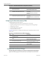
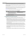
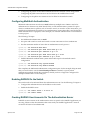
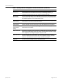
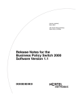
The number of allowed users per port can be configured using the set multiauth port numusers command. The show multiauth port command displays both the allowed number of users configured and the maximum number of users supported per port for the device. The allowed number of users defaults to the maximum number of supported users for the port for a modular switch platform and to 1 for the stackable fixed switch and standalone fixed switch platforms.
Note: Multi-user authentication on stackable fixed switch and standalone fixed switch platforms
requires that the switch be the point of authentication, in order to apply policy.
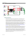
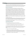
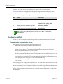
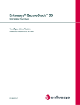
In Figure 1 each user on port ge.1.5 sends an authentication request to the RADIUS server. Based upon the Source MAC address (SMAC), RADIUS looks up the account for that user and includes the Filter‐ID associated with that account in the authentication response back to the switch (see section “The RADIUS Filter‐ID” on page 9 for Filter‐ID information). The policy specified in the Filter‐ID is then applied to the user. See section RFC 3580 on page 10 for information on dynamic VLAN assignment and tunnel attribute configuration.
April 15, 2011
Page 5 of 36
Authentication Overview
Figure 1
Applying Policy to Multiple Users on a Single Port
Authentication
Request
User 1
Switch
Authentication
Response
Radius Server
SMAC
00-00-00-11-11-11
Authentication
Credentials User 1
Authentication
Credentials User 2
Authentication
Request
Authentication
Credentials User 3
Authentication
Response
User 2
SMAC
00-00-00-22-22-22
Port ge.1.5
Authentication
Request
User 3
Dynamic Admin Rule
for Policy 1
SMAC = 00-00-00-11-11-11
ge.1.5
User1 Filter ID --> Policy X
Dynamic Admin Rule
for Policy 2
SMAC = 00-00-00-22-22-22
ge.1.5
User2 Filter ID --> Policy Y
Dynamic Admin Rule
for Policy 3
SMAC = 00-00-00-33-33-33
ge.1.5
User3 Filter ID --> Policy Z
Authentication
Response
SMAC
00-00-00-33-33-33
MultiAuth Authentication
Authentication mode support provides for the global setting of a single authentication mode 802.1X (strict‐mode) or multiple modes (MultiAuth) per user or port when authenticating. Strict mode is the appropriate mode when authenticating a single 802.1X user. All traffic on the port receives the same policy in strict mode. When authenticating PWA, CEP, or MAC, you must use MultiAuth authentication, whether authenticating a single or multiple supplicants.
MultiAuth authentication supports the simultaneous configuration of up to three authentication methods per user on the same port, but only one method per user is actually applied. When MultiAuth authentication ports have a combination of authentication methods enabled, and a user is successfully authenticated for more than one method at the same time, the configured authentication method precedence will determine which RADIUS‐returned Filter‐ID will be processed and result in an applied traffic policy profile. See “Setting MultiAuth Authentication Precedence” on page 21 for authentication method precedence details.
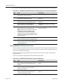
The number of users or devices MultiAuth authentication supports depends upon the type of device, whether the ports are fixed access or uplink, and whether increased port capacity or extra chassis user capacity MUA licenses have been applied. See the firmware customer release note that comes with your device for details on the number of users or devices supported per port.
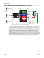
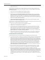
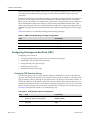
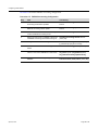
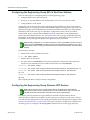
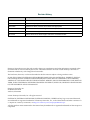
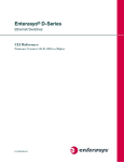
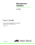
In Figure 2, multiple users are authenticated on a single port each with a different authentication method. In this case, each user on a single port successfully authenticates with a different authentication type. The authentication method is included in the authentication credentials sent to the RADIUS server. RADIUS looks up the user account for that user based upon the SMAC. The Filter‐ID for that user is returned to the switch in the authentication response, and the authentication is validated for that user.
April 15, 2011
Page 6 of 36
Authentication Overview
Figure 2
Authenticating Multiple Users With Different Methods on a Single Port
Authentication
Method
802.1x
Switch
Radius Server
User 1
SMAC
00-00-00-11-11-11
MAU Logic
Authentication
Method
PWA
User 2
SMAC
00-00-00-22-22-22
802.1X
User 1: 802.1X
Authentication
Credentials
PWA
User 2: PWA
Authentication
Credentials
MAC
User 3: MAC
Authentication
Credentials
Port
CEP
Authentication
Method
MAC
User1 Filter ID --> Policy Y
User2 Filter ID --> Policy X
User 3
SMAC
00-00-00-33-33-33
User3 Filter ID --> Policy Z
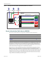
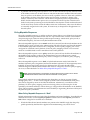
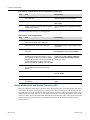
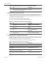
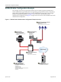
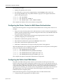
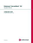
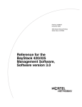
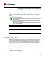
In Figure 3, full MultiAuth authentication takes place in that multiple users on a single port are validated for more than one authentication method. The applied authentication and policy are based upon the authentication method precedence level. On the far right column of the figure, the authentication methods are listed from top to bottom in order of precedence (the default order is displayed). User 1 is authenticating with both the 802.1x and PWA methods, with the Credit policy. Both the 802.1x and PWA authentication methods are validated, but only the 802.1x MultiAuth session is applied, because that has the highest precedence. User 2 is authenticating with both PWA and MAC methods, with the Sales policy. PWA, having a higher precedence than MAC, is the MultiAuth session applied for User 2. User 3 is a guest and is authenticating with the MAC method only. The MAC MultiAuth session, with the Guest policy is applied for User 3.
April 15, 2011
Page 7 of 36
Authentication Overview
Figure 3
Selecting Authentication Method When Multiple Methods are Validated
SMAC=User 1
SMAC=User 2
SMAC=User 3
Switch
MultiAuth Sessions
Auth. Agent
<User 1, 802.1x, Authenticated, PID=Credit, Applied>
802.1X
Credit
Policy Role
Port X
MAU Logic
Sales
Policy Role
<User 2, PWA, Authenticated, PID=Sales, Applied>
<User 1, PWA, Authenticated, PID=Credit, Not Applied>
PWA
<User 3, MAC, Authenticated, PID=Guest, Applied>
<User 1, MAC, Authenticated, PID=Guest, Not Applied>
MAC
<User 2, MAC, Authenticated, PID=Guest, Not Applied>
Guest
Policy Role
CEP
Remote Authentication Dial-In Service (RADIUS)
This section provides details for the configuration of RADIUS and RFC 3580 attributes.
For information about...
Refer to page...
How RADIUS Data Is Used
9
The RADIUS Filter-ID
9
RFC 3580
10
Policy Maptable Response
12
The Remote Authentication Dial‐In User Service (RADIUS) is an extensible protocol used to carry authentication and authorization information between the switch and the Authentication Server (AS). RADIUS is used by the switch for communicating supplicant supplied credentials to the authentication server and the authentication response from the authentication server back to the switch. This information exchange occurs over the link‐layer protocol. The switch acts as a client to RADIUS using UDP port 1812 by default (configurable in the set radius command). The authentication server contains a database of valid supplicant user accounts with their corresponding credentials. The authentication server checks that the information received from the switch is correct, using authentication schemes such as PAP, CHAP, or EAP. The authentication server returns an Accept or Reject message to the switch based on the credential validation performed by RADIUS. The implementation provides enhanced network security by using a shared secret and MD5 password encryption. April 15, 2011
Page 8 of 36
Authentication Overview
Required authentication credentials depend upon the authentication method being used. For 802.1x and PWA authentication, the switch sends username and password credentials to the authentication server. For MAC authentication, the switch sends the device MAC address and a password configured on the switch to the authentication server. The authentication server verifies the credentials and returns an Accept or Reject message back to the switch. How RADIUS Data Is Used
The Enterasys switch bases its decision to open the port and apply a policy or close the port based on the RADIUS message, the portʹs default policy, and unauthenticated behavior configuration. RADIUS provides accounting functionality by way of accounting packets from the switch to the RADIUS server, for such session statistics as start and end, total packets, and session end reason events. This data can be used for both billing and network monitoring purposes.
Additionally RADIUS is widely used by VoIP service providers. It is used to pass login credentials of a SIP end point (like a broadband phone) to a SIP Registrar using digest authentication, and then to the authentication server using RADIUS. Sometimes it is also used to collect call detail records (CDRs) later used, for instance, to bill customers for international long distance.
If you configure an authentication method that requires communication with an authentication server, you can use the RADIUS Filter‐ID attribute to dynamically assign either a policy profile or management level to authenticating supplicants.
The RADIUS Filter-ID
The RADIUS Filter‐ID attribute consists of a string that is formatted in the RADIUS Access‐Accept packet sent back from the authentication server to the switch during the authentication process. Each user can be configured in the RADIUS server database with a RADIUS Filter‐ID attribute that specifies the name of either a policy profile or management level the user should be assigned upon successful authentication. During the authentication process, when the authentication server returns a RADIUS Access‐Accept packet that includes a Filter‐ID matching a policy profile name configured on the switch, the switch then dynamically applies the policy profile to the physical port the supplicant is authenticating on.
The decorated Filter‐ID supports a policy attribute, a management access attribute, or both in the following formats:
Enterasys:version=1:policy=policyname
Enterasys:version=1:mgmt=access-mgmtType
Enterasys:version=1:mgmt=access-mgmtType:policy=policyname
policyname is the name of the policy to apply to this authentication.
access‐mgmtTypes supported are: ro (read‐only), rw (read‐write), and su (super‐user).
The un‐decorated Filter‐ID supports the policy attribute only in the following format:
policyname
The undecorated format is simply a string that specifies a policy profile name. The undecorated format cannot be used for management access authentication. Decorated Filter‐IDs are processed first. If no decorated Filter‐IDs are found, then undecorated Filter‐IDs are processed. If multiple Filter‐IDs are found that contain conflicting values, a Syslog message is generated.
April 15, 2011
Page 9 of 36
Authentication Overview
RFC 3580
Enterasys switches support the RFC 3580 RADIUS tunnel attribute for dynamic VLAN assignment. The VLAN‐Tunnel‐Attribute implements the provisioning of service in response to a successful authentication. On ports that do not support policy, the packet will be tagged with the VLAN‐ID. The VLAN‐Tunnel‐Attribute defines the base VLAN‐ID to be applied to the user.
Dynamic VLAN Assignment
The RADIUS server may optionally include RADIUS tunnel attributes in a RADIUS Access‐Accept message for dynamic VLAN assignment of the authenticated end system.
RFC 3580’s RADIUS tunnel attributes are often configured on a RADIUS server to dynamically assign users belonging to the same organizational group within an enterprise to the same VLAN, or to place all offending users according to the organization’s security policy in a Quarantine VLAN. Tunnel attributes are deployed for enterprises that have end system authentication configured on the network. For example, all engineers can be dynamically assigned to the same VLAN upon authentication, while sales are assigned to another VLAN upon authentication.
The name of the feature on Enterasys platforms that implements dynamic VLAN assignment through the receipt of RADIUS tunnel attributes is VLAN authorization. VLAN authorization depends upon receipt of the RFC 3580 RADIUS tunnel attributes in RADIUS Access‐Accept messages. VLAN authorization must be enabled globally and on a per‐port basis for the Tunnel attributes to be processed. When disabled per port or globally, the device will not process Tunnel attributes. The firmware supports VLAN authorization on the modular swithches, stackable fixed switches, and standalone fixed switches. By default, all policy‐capable Enterasys platforms will dynamically assign a policy profile to the port of an authenticating user based on the receipt of the Filter‐ID RADIUS attribute. This is not the case for RADIUS tunnel attributes in that, by default, VLAN authorization is disabled. The N‐Series, starting in firmware release 5.31.xx, the S‐Series, and K‐Series platforms support RFC 3580 RADIUS VLAN Tunnel attributes .
VLAN Authorization Attributes
Three Tunnel attributes are used for dynamic VLAN Authorization:
•
Tunnel‐Type attribute (Type=64, Length=6, Tag=0, Value=0x0D for VLAN)
•
Tunnel‐Medium‐Type attribute (Type=65, Length=6, Tag=0, Value=0x06 for 802 media)
•
Tunnel‐Private‐Group‐ID attribute (Type=81, Length>=3, String=VID in ASCII)
The Tunnel‐Type attribute indicates the tunneling protocol to be used when this attribute is formatted in RADIUS Access‐Request messages, or the tunnel protocol in use when this attribute is formatted in RADIUS Access‐Accept messages. Set Tunnel‐Type attribute parameters as follows:
April 15, 2011
•
Type: Set to 64 for Tunnel‐Type RADIUS attribute
•
Length: Set to 6 for six‐byte length of this RADIUS attribute
•
Tag: Provides a means of grouping attributes in the same packet which refer to the same tunnel. Valid values for this field are from 0x01 through 0x1F, inclusive. Set to 0 if unused. Unless alternative tunnel types are provided, it is only necessary for tunnel attributes to specify a single tunnel. As a result, where it is only desired to specify the VLAN‐ID, the tag field should be set to zero (0x00) in all tunnel attributes.
Page 10 of 36
Authentication Overview
•
Value: Indicates the type of tunnel. A value of 0x0D (decimal 13) indicates that the tunneling protocol is a VLAN.
Tunnel‐Medium‐Type indicates the transport medium to use when creating a tunnel for the tunneling protocol, determined from Tunnel‐Type attribute. Set Tunnel‐Medium‐Type attribute parameters as follows:
•
Type: Set to 65 for Tunnel‐Medium‐Type RADIUS attribute
•
Length: Set to 6 for six‐byte length of this RADIUS attribute
•
Tag: Provides a means of grouping attributes in the same packet which refer to the same tunnel. Valid value for this field are 0x01 through 0x1F, inclusive. Set to 0 if unused. Unless alternative tunnel types are provided, it is only necessary for tunnel attributes to specify a single tunnel. As a result, where it is only desired to specify the VLANID, the tag field should be set to zero (0x00) in all tunnel attributes.
•
Value: Indicates the type of tunnel. A value of 0x06 indicates that the tunneling medium pertains to 802 media (including Ethernet)
Tunnel‐Private‐Group‐ID attribute indicates the group ID for a particular tunneled session. Set the Tunnel‐Private‐Group‐ID attribute parameters as follows:
•
Type: Set to 81 for Tunnel‐Private‐Group‐ID RADIUS attribute
•
Length: Set to a value greater than or equal to 3.
•
Tag: Provides a means of grouping attributes in the same packet which refer to the same tunnel. Valid values for this field are from 0x01 through 0x1F, inclusive. Set to 0 if unused. Unless alternative tunnel types are provided, it is only necessary for tunnel attributes to specify a single tunnel. As a result, where it is only desired to specify the VLANID, the tag field should be set to zero (0x00) in all tunnel attributes.
•
String: Indicates the group. For the VLAN ID integer value, it is encoded as a string using ASCII. For example, the VLAN ID integer value 103 would be represented as 0x313033
VLAN Authorization Considerations
VLAN Authorization poses some operational and management issues on the network.
April 15, 2011
•
A VLAN is not a security container. It is a broadcast container and used to segment broadcast traffic on the network. ACLs implemented at the layer 3 routed interface for a VLAN only provide access control for traffic into and out of the VLAN. No access control mechanism for intra‐VLAN communications exists, therefore users within the VLAN are not protected from each other. Malicious traffic allowed onto a VLAN can potentially infect all traffic on the VLAN. Such an infection can consume valuable hardware resources on the infrastructure, such as CPU cycles and memory. Infections can be transmitted to other hosts within the VLAN and to the layer 3 routed boundary. This leads to the direct competition of malicious traffic with business critical traffic on the network.
•
End‐To‐End QoS cannot be truly guaranteed if QoS is implemented at the layer 3 routed interface for a network where business critical applications are classified and prioritized. •
If VLANs are implemented to group together users that are members of the same organizational group, then a VLAN must be configured everywhere in the network topology where a member of that organizational unit may connect to the network. For example, if an engineer may connect to the network from any location, then the Engineering VLAN must be configured on all access layer devices in the network. These VLAN configurations lead to over‐extended broadcast domains as well as added configuration complexity in the network topology.
Page 11 of 36
Authentication Overview
•
A problem with moving an end system to a new VLAN is that the end system must be issued an IP address on the new VLAN’s subnet to which it has become a member. If the end system does not yet have an IP address, this is not usually a problem. However, if the end system has an IP address, the lease of the address must time out before it attempts to obtain a new address, which may take some time. The IP address assignment process, implemented by DHCP, and the authentication process are not conjoined on the end system. Therefore, this leads to end systems possessing an invalid IP address after dynamic VLAN Authorization and lost IP connectivity until its current IP address times out. Furthermore, when a new IP address is eventually assigned to the end system, IP connectivity is disrupted for all applications on the end system.
Policy Maptable Response
The policy maptable response, or conflict resolution, feature allows you to define how the system should handle allowing an authenticated user onto a port based on the contents of the RADIUS Accept message reply. There are three possible response settings: tunnel mode, policy mode, or both tunnel and policy, also known as hybrid authentication mode.
When the maptable response is set to tunnel mode, the system will use the tunnel attributes in the RADIUS reply to apply a VLAN to the authenticating user and will ignore any Filter‐ID attributes in the RADIUS reply. When tunnel mode is configured, VLAN‐to‐policy mapping can occur if configured on a modular switch platform. VLAN‐to‐policy mapping will not occur in tunnel mode on a stackable fixed switch or standalone fixed switch platform. When the maptable response is set to policy mode, the system will use the Filter‐ID attributes in the RADIUS reply to apply a policy to the authenticating user and will ignore any tunnel attributes in the RADIUS reply. When policy mode is configured, no VLAN‐to‐policy mapping will occur.
When the maptable response is set to both, or hybrid authentication mode, both Filter‐ID attributes (dynamic policy assignment) and tunnel attributes (dynamic VLAN assignment) sent in RADIUS Accept message replies are used to determine how the switch should handle authenticating users. When hybrid authentication mode is configured, VLAN‐to‐policy mapping can occur, as described below in When Policy Maptable Response is “Both”.
Note: Hybrid authentication is supported by modular switch devices, B-Series and C-Series
stackable fixed switches and the G3 device for Releases 6.3 and greater.
Using hybrid authentication mode eliminates the dependency on having to assign VLANs through policy roles — VLANs can be assigned by means of the tunnel attributes while policy roles can be assigned by means of the Filter‐ID attributes. Alternatively, on modular switch platforms, VLAN‐to‐policy mapping can be used to map policies to users using the VLAN specified by the tunnel attributes, without having to configure Filter‐ID attributes on the RADIUS server. This separation gives administrators more flexibility in segmenting their networks beyond the platform’s policy role limits. When Policy Maptable Response is “Both”
Hybrid authentication mode uses both Filter‐ID attributes and tunnel attributes. To enable hybrid authentication mode, use the set policy maptable command and set the response parameter to both. When configured to use both sets of attributes:
•
April 15, 2011
If both the Filter‐ID and tunnel attributes are present in the RADIUS reply, then the policy profile specified by the Filter‐ID is applied to the authenticating user, and if VLAN Page 12 of 36
Authentication Overview
authorization is enabled globally and on the authenticating user’s port, the VLAN specified by the tunnel attributes is applied to the authenticating user. If VLAN authorization is not enabled, the VLAN specified by the policy profile is applied. See “RFC 3580” on page 10 for information about VLAN authorization.
•
If the Filter‐ID attributes are present but the tunnel attributes are not present, the policy profile specified by the Filter‐ID is applied, along with the VLAN specified by the policy profile.
•
If the tunnel attributes are present but the Filter‐ID attributes are not present, and if VLAN authorization is enabled globally and on the authenticating user’s port, then the switch will check the VLAN‐to‐policy mapping table (configured with the set policy maptable command):
–
If an entry mapping the received VLAN ID to a policy profile is found, then that policy profile, along with the VLAN specified by the policy profile, will be applied to the authenticating user.
–
If no matching mapping table entry is found, the VLAN specified by the tunnel attributes will be applied to the authenticating user.
–
If the VLAN‐to‐policy mapping table is invalid, then the etsysPolicyRFC3580MapInvalidMapping MIB is incremented and the VLAN specified by the tunnel attributes will be applied to the authenticating user.
If VLAN authorization is not enabled, the tunnel attributes are ignored.
When Policy Maptable Response is “Profile”
When the switch is configured to use only Filter‐ID attributes, by setting the set policy maptable command response parameter to policy:
•
If the Filter‐ID attributes are present, the specified policy profile will be applied to the authenticating user. If no Filter‐ID attributes are present, the default policy (if it exists) will be applied.
•
If the tunnel attributes are present, they are ignored. No VLAN‐to‐policy mapping will occur.
When Policy Maptable Response is “Tunnel”
When the switch is configured to use only tunnel attributes, by setting the set policy maptable command response parameter to tunnel, and if VLAN authorization is enabled both globally and on the authenticating user’s port:
•
If the tunnel attributes are present, the specified VLAN will be applied to the authenticating user. VLAN‐to‐policy mapping can occur on a modular switch platform; VLAN‐to‐policy mapping will not occur on a stackable fixed switch or standalone fixed switch platform.
•
If the tunnel attributes are not present, the default policy VLAN will be applied; if the default policy VLAN is not configured, the port VLAN will be applied. •
If the Filter‐ID attributes are present, they are ignored.
If VLAN authorization is not enabled, the user will be allowed onto the port with the default policy, if it exists. If no default policy exists, the port VLAN will be applied.
April 15, 2011
Page 13 of 36
Configuring Authentication
Configuring Authentication
This section provides details for the configuration of authentication methods, MultiAuth and RADIUS.
For information about...
Refer to page...
Configuring IEEE 802.1x
16
Configuring MAC-based Authentication
17
Configuring Port Web Authentication (PWA)
18
Configuring Convergence End Point (CEP)
19
Configuring MultiAuth Authentication
21
Configuring RADIUS
26
Table 1 lists Authentication parameters and their default values. Table 1
April 15, 2011
Default Authentication Parameters
Parameter
Description
Default Value
cep port
Enables or disables CEP for the
specified port.
Disabled.
dot1x
Enables and disables 802.1x
authentication both globally and per
port.
Globally: Disabled.
dot1x authconfig
Configures 802.1x authentication.
auto - auto authorization mode.
macauthentication
Globally enables or disables MAC
authentication on a device.
Disabled.
macauthentication
authallocated
Sets the number of MAC
authentication sessions supported on
the specified port
Based upon the device and license.
See the firmware release notes for
your device.
macauthentication port
Enables or disables MAC
authentication on a port
Disabled.
MultiAuth idle-timeout
Specifies the period length for which
no traffic is received before a MultiAuth
session is set to idle.
300 seconds.
MultiAuth mode
Globally sets MultiAuth for this device.
strict - authentication limited to 802.1x
for a single user on a port.
MultiAuth port mode
Specifies the MultiAuth port mode to
use for the specified port.
auth-opt - Authentication is optional
based upon global and port
configuration.
MultiAuth precedence
Specifies the authentication mode to
use when multiple authentication types
are successfully authenticated.
Precedence from high to low: 802.1x,
PWA, MAC, CEP.
MultiAuth
session-timeout
Specifies the maximum amount of time
a session can live.
0 - no timeout in effect.
Per Port: Enabled.
Page 14 of 36
Configuring Authentication
Table 1
April 15, 2011
Default Authentication Parameters (continued)
Parameter
Description
Default Value
pwa
Globally enables or disables PWA
authentication.
Disabled.
pwa enhancemode
Allows a user on an un-authenticated
port to enter any URL in the browser to
access the login page.
Disabled.
radius
Enable or disable RADIUS on this
device.
Disabled.
radius accounting
Enables or disables RADIUS
accounting for this device.
Disabled.
radius accounting
intervalminimum
Specifies the minimum interval before
sending updates for RADIUS
accounting.
600 seconds.
radius accounting retries
Specifies the number of times a switch
will attempt to contact an
authentication server for RADIUS
accounting that is not responding.
2.
radius accounting
timeout
Specifies the amount of time for a
switch to make contact with a RADIUS
server.
5 seconds.
radius accounting
updateinterval
Specifies the minimum interval
between interim updates for RADIUS
accounting.
1800 seconds.
radius retries
Specifies the number of times a switch
will try to establish with the
authentication server.
3.
radius timeout
Specifies the amount of time a switch
will wait to receive a response from the
authentication server before sending
another request.
20 seconds.
realm
Specifies authentication server
configuration scope.
Both: management-access and
network-access.
VLAN authorization
Enables or disables globally and per
port VLAN authorization.
Globally: Disabled.
Per Port: Enabled.
VLAN egress format
Determines whether dynamic VLAN
tagging will be none, tagged,
untagged, or dynamic for an egress
frame.
Untagged.
Page 15 of 36
Configuring Authentication
Configuring IEEE 802.1x
Configuring IEEE 802.1x on an authenticator switch port consists of:
•
Setting the authentication mode globally and per port
•
Configuring optional authentication port parameters globally and per port
•
Globally enabling 802.1x authentication for the switch
Procedure 1 describes how to configure IEEE 802.1x on an authenticator switch port. Unspecified parameters use their default values. Procedure 1
IEEE 802.1x Configuration
Step
Task
Command(s)
1.
Set the IEEE 802.1x authentication mode both
globally and per port:
set dot1x auth-config
{[authcontrolled-portcontrol {auto |
forced-auth | forced-unauth}]
[keytxenabled{false | true}] [maxreq value]
[quietperiod value] [reauthenabled {false |
true}] [reauthperiod value] [servertimeout
timeout] [supptimeout timeout] [txperiod
value]} [port-string]
• Auto - The switch will only forward
authenticated frames.
• Forced-auth - 802.1x authentication is
effectively disabled for this port. All received
frames are forwarded.
• Forced-unauth - 802.1x authentication is
effectively disabled on the port. If 802.1x is
the only authentication method on the port, all
frames are dropped.
Note: Before enabling 802.1x authentication on
the switch, you must set the authentication
mode of ports that will not be participating in
802.1x authentication to forced-authorized to
assure that frames will be forwarded on these
ports. Examples of this kind of port are
connections between switches and connections
between a switch and a router.
The setting of dot1x options other than
authcontrolled-portcontrol are optional.
April 15, 2011
2.
Display the access entity index values. Ports
used to authenticate and authorize supplicants
utilize access entities that maintain entity state,
counters, and statistics for an individual
supplicant. You need to know the index value
associated with a single entity to enable,
disable, initialize, or reauthenticate a single
entity.
show dot1x auth-session-stats
3.
Enable EAP on the stackable fixed switch or
standalone fixed switch. EAP is enabled on the
modular switch when enabling IEEE 802.1x. See
Step 4.
set eapol [enable | disable] [auth-mode
{auto | forced-auth | forced-unauth}
port-string
4.
Enable IEEE 802.1x globally on the switch.
Ports default to enabled.
set dot1x {enable | disable}
Page 16 of 36
Configuring Authentication
Procedure 1
IEEE 802.1x Configuration (continued)
Step
Task
Command(s)
5.
If an entity deactivates due to the supplicant
logging off, inability to authenticate, or the
supplicant or associated policy settings are no
longer valid, you can reinitialize a deactivated
access entity. If necessary, reinitialize the
specified entity.
set dot1x init [port-string] [index index-list]
6.
If the authentication for a supplicant times out or
is lost for any reason, you can reauthenticate
that supplicant. If necessary, reauthenticate the
specified entity.
set dot1x reauth [port-string] [index
index-list]
7.
Display IEEE 802.1x configuration.
show dot1x auth-config
Configuring MAC-based Authentication
Configuring MAC‐based authentication on a switch consists of:
•
Setting the global MAC authentication password for the switch
•
Optionally setting the number of MAC authentication sessions allowed on a port
•
Enabling MAC authentication on a port
•
Enabling MAC authentication globally
•
Setting the authentication mode to multi
•
Optionally reinitializing or reauthenticating existing sessions
Procedure 2 describes how to configure MAC‐based authentication. Unspecified parameters use their default values. Procedure 2
April 15, 2011
MAC-Based Authentication Configuration
Step
Task
Command(s)
1.
Optionally set or clear a global password on the
switch.
set macauthentication password password
2.
Set or clear the number of MAC authentication
sessions supported on a port. The modular
switch platform allows for the setting of the
number of MAC authentication sessions
supported on a port.
set macauthentication authallocated
number port-string
3.
Enable or disable MAC authentication on a port.
By default, MAC authentication is disabled for all
ports. MAC authentication must be enabled on
the ports that will use it.
set macauthentication port {enable |
disable}
4.
Enable or disable MAC authentication globally
on the device. By default, MAC authentication is
globally disabled on the device.
set macauthentication {enable | disable}
5.
Set the MultiAuth mode.
set multiauth mode multi
clear macauthentication password
password
Page 17 of 36
Configuring Authentication
Procedure 2
MAC-Based Authentication Configuration (continued)
Step
Task
Command(s)
6.
Display MAC authentication configuration or
status of active sessions.
show macauthentication
If a session or port requires reinitialization,
reinitialize a specific MAC session or port.
set macauthentication macinitialize
mac-address
7.
show macauthentication session
set macauthentication portinitialize
port-string
8.
If a session or port requires reauthentication,
reauthenticate a specific MAC session or port.
set macauthentication macreauthenticate
mac-address
set macauthentication portreauthenticate
port-string
Configuring Port Web Authentication (PWA)
Configuring PWA on the switch consists of:
•
Setting the IP address which the user will authenticate to on the switch
•
Optionally enabling PWA enhanced mode and configure guest networking privileges
•
Enabling PWA on the port
•
Globally enabling PWA on the switch
•
Setting the authentication mode
Procedure 3 describes how to configure PWA authentication. Unspecified parameters use their default values. Procedure 3
Port Web Authentication (PWA) Configuration
Step
Task
Command(s)
1.
Set the IP address for the end-station the
supplicant accesses.
set pwa ipaddress ip-address
2.
Optionally enable or disable PWA enhanced
mode.
set pwa enhancemode enable
Enable or disable PWA. PWA must be enabled
on the port for PWA to function.
set pwa portcontrol enable port-string
Globally enable or disable PWA on the switch.
set pwa enable
3.
4.
set pwa enhancemode disabled
set pwa portcontrol disable port-string
set pwa disabled
5.
Set the MultiAuth mode.
set multiauth mode multi
6.
Display PWA configuration.
show pwa
Optionally Enable Guest Network Privileges
With PWA enhanced mode enabled, you can optionally configure guest networking privileges. Guest networking allows an administrator to specify a set of credentials that will, by default, appear on the PWA login page of an end station when a user attempts to access the network. April 15, 2011
Page 18 of 36
Configuring Authentication
When enhanced mode is enabled, PWA will use a guest password and guest user name to grant network access with default policy privileges to users without established login names and passwords. In order to configure guest networking privileges, you need to set the guest status, user name, and password. You can set guest status for no authentication, RADIUS authentication, or disabled. When you set guest status to no authentication, guest status is provided with its associated policy, but no authentication takes place. When you set guest status to RADIUS authentication, guest status is provided only after a successful authentication takes place. If guest networking status is disabled, all supplicants must be authenticated with a valid user name and password at the login page.
Table 2 describes how to optionally enable guest networking privileges. Table 2
PWA Guest Networking Privileges Configuration
Task
Command(s)
Optionally enable guest status without authentication
set pwa gueststatus authnone
Optionally enable guest status with authentication.
set pwa gueststatus authradius
Optionally disable guest status
set pwa gueststatus disable
Configuring Convergence End Point (CEP)
Configuring CEP consists of:
•
Creating a CEP detection group for Non‐Cisco Detection CEP types
•
Enabling the CEP group for Cisco Detection
•
Setting the CEP policy per CEP type
•
Enabling CEP on the port
•
Setting the authentication mode
Creating a CEP Detection Group
CEP detection groups can be created, deleted, enabled, or disabled. You create a CEP detection group by associating an ID with the create command. Once a group is created, you associate a CEP type, IP address, protocol, and high or low protocol port to it. The type can be H.323, Siemens, or SIP. The IP address is the IP address of the CEP device. By default, H.323 will use 224.0.1.41 as its IP address and Siemens will have no IP address configured. The protocol can be TCP or UDP. The high or low protocol port is the maximum or minimum TCP or UDP port to be used by the group.
Procedure 4 describes the creation of a CEP detection group. Procedure 4
April 15, 2011
CEP Detection Group Configuration
Step
Task
Command(s)
1.
Create a new CEP detection group or enable,
disable, or delete an existing group.
set cep detection-id id {create | enable |
disable | delete}
2.
Specify the CEP type to be associated with the
this group.
set cep detection-id id type {h323 | siemens
| sip}
Page 19 of 36
Configuring Authentication
Procedure 4
CEP Detection Group Configuration (continued)
Step
Task
Command(s)
3.
Specify the CEP device IP address and mask or
set to unknown.
set cep detection-id id address {ip-address |
unknown} mask {mask | unknown}
4.
Set the CEP detection group protocol.
set cep detection-id id protocol {tcp | udp |
both | none}
5.
Set the maximum or minimum port for the TCP
or UDP group protocol.
set cep detection-id id {porthigh | portlow}
port
Procedure 5 describes the steps to configure CEP. Procedure 5
CEP Configuration
Step
Task
Command(s)
1.
Determine the policy profile index of the profile
you wish to associate with a CEP type.
show policy profile all
2.
Associate a policy profile with a CEP type.
set cep policy {cisco | h323 | siemens | sip}
policy-index
3.
Enable or disable the CEP device port for the
CEP type
set cep port port-string cep-type enable
set cep port port-string cep-type disable
4.
If you are using the Cisco discovery protocol,
enable the Cisco discovery protocol. You can
also optionally set the voice VLAN ID, whether
tagged traffic is trusted or untrusted, and 802.1X
priority transmitted to the Cisco IP phone to
format in the 802.1Q VLAN tag of its VoIP traffic.
set ciscodp port { [status {disable | enable}]
[ vvid {vlan-id | none | dot1p | untagged}]
[trust-ext {trusted | untrusted}] [cos-ext
value] } port-string
5.
If the Cisco discovery protocol is enabled on any
port, enable the Cisco discovery protocol
globally.
set ciscodp status
6.
Globally enable or disable CEP on the switch.
set cep enable
set cep disable
7.
Set the MultiAuth mode.
set multiauth mode multi
8.
Display CEP connections, detection, policy and
port settings.
show cep {connections | detection | policy
| port}
Setting MultiAuth Idle and Session Timeout for CEP
There is no means of detecting if a Siemens, SIP, or H323 phone goes away other than in the case of a link down. Therefore, if these types of phones are not directly connected to the switch port and the phone goes away, the switch will still see the phone connection and any configured policy will remain on the port. Detected CEPs will be removed from the connection table if they do not send traffic for a time equal to the MultiAuth authentication idle timeout value. CEPs are also removed if the total duration of the session exceeds the time specified in the MultiAuth authentication session timeout.
April 15, 2011
Page 20 of 36
Configuring Authentication
Procedure 6 describes setting the MultiAuth idle and session timeout for CEP. Procedure 6
DNS and DHCP Spoofing Configuration
Step
Task
Command(s)
1.
Optionally set the MultiAuth authentication idle
timeout for this switch.
set multiauth idle-timeout cep timeout
2.
Optionally set the MultiAuth authentication
session timeout for this switch.
set multiauth session-timeout cep timeout
Configuring MultiAuth Authentication
Configuring MultiAuth authentication consists of:
•
Setting MultiAuth authentication mode setting
•
Setting MultiAuth authentication precedence settings
•
Setting MultiAuth authentication port properties
•
Setting MultiAuth authentication idle timeout values
•
Setting MultiAuth authentication session timeout values
•
Setting MultiAuth authentication trap settings
Setting MultiAuth Authentication Mode
MultiAuth authentication mode can be set to MultiAuth or strict 802.1X single user mode. Set MultiAuth authentication to MultiAuth when multiple users need to be authenticated for 802.1X or in all cases for MAC, PWA, and CEP authentication.
Procedure 7 describes setting the MultiAuth authentication mode. Procedure 7
MultiAuth Authentication Configuration
Step
Task
Command(s)
1.
For a single user, single authentication 802.1x
port configuration, set MultiAuth mode to strict.
set multiauth mode strict
2.
For multiple user 802.1x authentication or any
non-802.1x authentication, set the system
authentication mode to use multiple
authenticators simultaneously.
set multiauth mode multi
3.
To clear the MultiAuth authentication mode.
clear multiauth mode
Setting MultiAuth Authentication Precedence
MultiAuth authentication administrative precedence globally determines which authentication method will be selected when a user is successfully authenticated for multiple authentication methods on a single port. When a user successfully authenticates more than one method at the same time, the precedence of the authentication methods will determine which RADIUS‐returned Filter‐ID will be processed and result in an applied traffic policy profile. MultiAuth authentication precedence defaults to the following order from high to low: 802.1x, PWA, MAC, and CEP (802.1x, PWA, and MAC on stackable fixed switch and standalone fixed April 15, 2011
Page 21 of 36
Configuring Authentication
switch devices). You may change the precedence for one or more methods by setting the authentication methods in the order of precedence from high to low. Any methods not entered are given a lower precedence than the methods entered in their pre‐existing order. For instance, if you start with the default order and only set PWA and MAC, the new precedence order will be PWA, MAC, 802.1x, and CEP. Given the default order of precedence (802.1x, PWA, MAC, and CEP), if a user was to successfully authenticate with PWA and MAC, the authentication method RADIUS Filter‐ID applied would be PWA, because it has a higher position in the order. A MAC session would authenticate, but its associated RADIUS Filter‐ID would not be applied.
Procedure 8 describes setting the order for MultiAuth authentication precedence. Procedure 8
MultiAuth Authentication Precedence Configuration
Step
Task
Command(s)
1.
Set a new order of precedence for the selection
of the RADIUS Filter-ID that will be returned
when multiple authentication methods are
authenticated at the same time for a single user.
set multiauth precedence {[dot1x] [mac]
[pwa] [cep] [radius-snooping]}
2.
Reset the order MultiAuth authentication
precedence to the default values.
clear multiauth precedence
Setting MultiAuth Authentication Port Properties
MultiAuth authentication supports the configuration of MultiAuth port and maximum number of users per port properties. The MultiAuth port property can be configured as follows:
April 15, 2011
•
Authentication Optional – Authentication methods are active on the port based upon the global and port authentication method. Before authentication succeeds, the current policy role applied to the port is assigned to the ingress traffic. This is the default role if no authenticated user or device exists on the port. After authentication succeeds, the user or device is allowed to access the network according to the policy information returned from the authentication server, in the form of the RADIUS Filter‐ID attribute, or the static configuration on the switch. This is the default setting.
•
Authentication Required – Authentication methods are active on the port, based on the global and per port authentication method configured. Before authentication succeeds, no traffic is forwarded onto the network. After authentication succeeds, the user or device gains access to the network based upon the policy information returned by the authentication server in the form of the RADIUS Filter‐ID attribute, or the static configuration on the switch. •
Force Authenticated – The port is completely accessible by all users and devices connected to the port, all authentication methods are inactive on the port, and all frames are forwarded onto the network.
•
Force Unauthenticated – The port is completely closed for access by all users and devices connected to the port. All authentication methods are inactive and all frames are discarded. Page 22 of 36
Configuring Authentication
Procedure 9 describes setting the MultiAuth authentication port and maximum user properties. Procedure 9
MultiAuth Authentication Port and Maximum User Properties Configuration
Step
Task
Command(s)
1.
Set the specified ports to the MultiAuth
authentication optional port mode.
set multiauth port mode auth-opt port-string
2.
Set the specified ports to the MultiAuth
authentication required port mode.
set multiauth port mode auth-reqd
port-string
3.
Set the specified ports to the MultiAuth
authentication force authenticated port mode.
set multiauth port mode force-auth
port-string
4.
Set the specified ports to the MultiAuth
authentication force unauthenticated port mode.
set multiauth port mode force-unauth
port-string
5.
Optionally set the maximum number of
authenticated users for the specified port.
set multiauth port mode numusers
numusers port-string
Notes: This value can be set to any value up to
the maximum number of MultiAuth users
supported for the device. See the firmware
release notes that come with your device for the
maximum number of supported MultiAuth users
the device supports.
6.
Reset the ports MultiAuth authentication port
clear multiauth port mode port-string
mode to the default value for the specified ports.
7.
Reset the ports MultiAuth authentication port
maximum number of users to the default value
for the specified ports.
clear multiauth port numusers port-string
Setting MultiAuth Authentication Timers
The idle timeout setting determines the amount of idle time in which no traffic transits the link for a user or device before the connection is removed from the connection table. The idle timeout can be set for any authentication method. The session timeout setting determines the maximum amount of time a session can last before being terminated. Procedure 10 describes setting the MultiAuth authentication timers. Procedure 10
April 15, 2011
MultiAuth Authentication Timers Configuration
Step
Task
Command(s)
1.
Optionally set the MultiAuth authentication idle
timeout value for the specified authentication
method.
set multiauth idle-timeout auth-method
timeout
2.
Reset the MultiAuth authentication idle timeout
value to its default value for the specified
authentication method.
clear multiauth idle-timeout auth-method
3.
Optionally set the maximum amount of time a
session can last before termination for the
specified authentication method.
set multiauth session-timeout auth-method
timeout
Page 23 of 36
Configuring Authentication
Procedure 10
MultiAuth Authentication Timers Configuration (continued)
Step
Task
Command(s)
4.
Reset the maximum amount of time a session
can last before termination to the default value
for the specified authentication method.
clear multiauth session-timeout
auth-method
Setting MultiAuth Authentication Traps
Traps can be enabled at the system and module levels when the maximum number of users for the system and module, respectively, have been reached. Traps can be enabled at the port level for authentication success, failure, termination and when the maximum number of users have been reached on the port or all supported traps.
The modular switch platforms support authentication traps
Procedure 11 describes setting the MultiAuth authentication traps. Procedure 11
MultiAuth Authentication Traps Configuration
Step
Task
Command(s)
1.
Optionally enable MultiAuth authentication
system traps.
set multiauth trap system {enabled |
disabled}
2.
Optionally enable MultiAuth authentication
module traps.
set multiauth trap module {enabled |
disabled}
3.
Optionally enable MultiAuth authentication port
traps.
set multiauth trap port port-string {all |
success | failed | terminated |
max-reached}
4.
Disable MultiAuth authentication traps for the
specified trap type.
clear multiauth trap trap-type {all | success
| failed | terminated | max-reached}
Displaying MultiAuth Configuration Information
MultiAuth authentication supports the display of system‐wide MultiAuth authentication values, MultiAuth authentication counters, port settings, end‐user MAC addresses, session information, idle timeout settings, session timeout settings, and trap settings.
Table 3 describes displaying of MultiAuth authentication settings and statistics. Table 3
April 15, 2011
MultiAuth Authentication Traps Configuration
Task
Command(s)
Display system-wide MultiAuth authentication values.
show multiauth
Display MultiAuth authentication counters.
show multiauth counters
Display MultiAuth authentication port settings for all or the
specified ports.
show multiauth port [port-string]
Display end-user MAC addresses per port for all MAC
addresses and ports or for those specified.
show multiauth station [mac-address]
[port-string]
Display MultiAuth authentication sessions for all sessions
or the specified authentication method, MAC address, or
ports.
show multiauth session [agent
auth-method] [mac-address] [port-string]
Page 24 of 36
Configuring Authentication
Table 3
MultiAuth Authentication Traps Configuration (continued)
Task
Command(s)
Display MultiAuth authentication idle timeout values.
show multiauth idle-timeout
Display MultiAuth authentication session timeout values.
show multiauth session-timeout
Display MultiAuth authentication trap settings.
show multiauth trap
Configuring VLAN Authorization
VLAN authorization allows for the dynamic assignment of users to the same VLAN. You configure VLAN authorization attributes within RADIUS. On the switch you enable VLAN authorization both globally and per‐port. VLAN authorization is disabled globally by default. VLAN authorization is enabled per port by default. You can also set the VLAN egress format per‐port. VLAN egress format defaults to un‐tagged. VLAN egress format can be set as follows:
•
none – No egress manipulation will be made.
•
tagged – The authenticating port will be added to the current tagged egress for the VLAN‐ID returned.
•
untagged – The authenticating port will be added to the current untagged egress for the VLAN‐ID returned.
•
dynamic – Egress formatting will be based upon information contained in the authentication response. The VLAN authorization table will always list any tunnel attribute’s VIDs that have been received for authenticated end systems, but a VID will not actually be assigned unless VLAN authorization is enabled both globally and on the authenticating port. Dynamic VLAN authorization overrides the port PVID. Dynamic VLAN authorization is not reflected in the show port vlan display. The VLAN egress list may be statically configured, enabled based upon the set vlanauthorization egress command, or have dynamic egress enabled to allow full VLAN membership and connectivity. Procedure 12 describes setting VLAN authorization configuration. Procedure 12
VLAN Authorization Configuration
Step
Task
Command(s)
1.
Enable or disable VLAN authorization both
globally and per port.
set vlanauthorization {enable | disable}
2.
Reset VLAN authorization configuration to
default values for the specified port-list or for all.
clear valanauthorization {port-list | all}
3.
Display VLAN authorization configuration
settings for the specified port-list or for all.
show vlanauthorization {port-list | all}
Setting Dynamic Policy Profile Assignment and Invalid Policy Action
Dynamic policy profile assignment is implemented using the policy mapping table. When VLAN authorization is enabled, authenticated users are dynamically assigned to the received tunnel attribute’s VID, unless preempted by a policy map‐table configuration entry. Dynamic policy profile assignment is supported by mapping a VID to a policy role upon receipt of a RADIUS tunnel attribute. April 15, 2011
Page 25 of 36
Configuring Authentication
If the authentication server returns an invalid policy or VLAN to a switch for an authenticating supplicant, an invalid action of forward, drop, or default policy can be configured.
Procedure 13 describes setting dynamic policy profile assignment and invalid policy action configuration. Procedure 13
Policy Profile Assignment and Invalid Action Configuration
Step
Task
Command(s)
1.
Identify the profile index to be used in the
VID-to-policy mapping.
show policy profile all
2.
Map the VLAN ID to the profile index.
set policy maptable {vlan-list profile-index |
response {tunnel | policy | both}}
3.
Display the current maptable configuration.
show policy maptable.
4.
Set the action to take when an invalid policy or
VLAN is received by the authenticating switch.
set policy invalid action {default-policy |
drop | forward}
Note: Dynamic policy profile assignment is supported on the Matrix E1 and modular
switch platforms.
Configuring RADIUS
You can set, clear, and display RADIUS configuration for both authentication and accounting. Configuring the Authentication Server
There are four aspects to configuring the authentication server:
•
State enables or disables the RADIUS client for this switch.
•
Establishment values configure a timer setting the length of time before retries, as well as the number of retries, before the switch determines the authentication server is down and attempts to establish with the next server in its list.
•
Server identification provides for the configuration of the server IP address and index value. The index determines the order in which the switch will attempt to establish a session with an authentication server. After setting the index and IP address you are prompted to enter a secret value for this authentication server. Any authentication requests to this authentication server must present the correct secret value to gain authentication. •
The realm provides for configuration scope for this server: management access, network access, or both.
Firmware supports the configuration of multiple ASs. The lowest index value associated with the server determines the primary server. If the primary server is down, the operational server with the next lowest index value is used. If the switch fails to establish contact with the authentication server before a configured timeout, the switch will retry for the configured number of times. Servers can be restricted to management access or network access authentication by configuring the realm option. April 15, 2011
Page 26 of 36
Configuring Authentication
Procedure 14 describes authentication server configuration. Procedure 14
Authentication Server Configuration
Step
Task
Command(s)
1.
Configure the index value, IP address, and
secret value for this authentication server.
set radius server index ip-address
[secret-value]
2.
Optionally set the number of seconds the switch
will wait before retrying authentication server
establishment.
set radius timeout timeout
3.
Optionally set the number of retries that will
occur before the switch declares an
authentication server down.
set radius retries retries
4.
Optionally set the authentication server
configuration scope to management access,
network access, or both for all or the specified
authentication server.
set radius realm {management-access |
network-access | any} {as-index | all}
5.
Globally enable or disable RADIUS on the
switch.
set radius {enable | disable}
6.
Reset the specified RADIUS setting to its default
value.
clear radius {[state] [retries] [timeout]
[server [index | all] [realm {index | all}]
7.
Display the current RADIUS authentication
server settings.
show radius [state | retries | authtype |
timeout | server [index | all]]
Configuring RADIUS Accounting
There are four aspects to configuring RADIUS accounting: •
State enables or disables RADIUS accounting
•
Update values allow the specification of the length of the period before accounting updates start and the interval between updates
•
Establishment values configure a timer setting the length of time before retries, as well as the number of retries, before the switch determines the RADIUS accounting server is down and attempts to establish with the next server in its list.
•
Server identification provides for the configuration of the RADIUS accounting server IP address and index value. The index determines the order in which the switch will attempt to establish with an accounting server. After setting the index and IP address you are prompted to enter a secret value for this accounting server. Firmware supports the configuration of multiple RADIUS accounting servers. The lowest index value associated with the server determines the primary server. If the primary server is down, the operational server with the next lowest index value is used. If the switch fails to establish contact with the primary server before a configured timeout, the switch will retry for the configured number of times. April 15, 2011
Page 27 of 36
Configuring Authentication
Procedure 15 describes RADIUS accounting configuration. Procedure 15
April 15, 2011
RADIUS Accounting Configuration
Step
Task
Command(s)
1.
Set the minimum interval at which RADIUS
accounting sends interim updates.
set radius accounting intervalminimum
interval
2.
Set the number of seconds between each
RADIUS accounting interim update.
set radius accounting updateinterval
interval
3.
Set the number of times a switch will attempt to
contact a RADIUS accounting server.
set radius accounting retries retries
4.
Set the amount of time to establish contact with
a RADIUS accounting server before timing out.
set radius accounting timeout timeout
{index | all}
5.
Configure the RADIUS accounting server.
set radius accounting server {index | all}
ip_address udp-port [server-secret]
6.
Enable or disable RADIUS accounting on this
switch.
set radius accounting {enable | disable}
7.
Reset RADIUS accounting parameters to default
values or clear server definitions on this switch.
clear radius accounting {[server {index |
all}] [retries {index | all}] [timeout {index |
all}] [intervalminimum] [updateinterval]}
8.
Display RADIUS accounting configuration or
statistics.
show radius accounting [updateinterval |
intervalminimum | state | server {index | all}]
Page 28 of 36
Authentication Configuration Example
Authentication Configuration Example
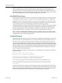
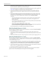
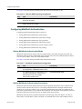
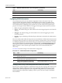
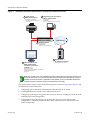
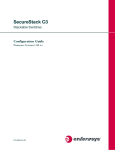
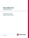
Our example covers the four supported modular switch and three supported stackable fixed switch authentication types being used in an engineering group: end‐user station, an IP phone, a printer cluster, and public internet access. For the stackable fixed switch devices, the example assumes C3 platform capabilities. See Figure 4 for an overview of the modular switch authentication configuration and Figure 5 on page 30 for an overview of the stackable fixed switch authentication configuration.
Figure 4
Modular Switch Authentication Configuration Example Overview
3
Engineering end-user stations
801.1x authentication
Enable 802.1x
Set non-Authentication ports to force-auth
5
4
Printer cluster
MAC Authentication
Enable MAC authentication
Set MAC authentication password
Enable Port
Engineering Group
Siemens CEP
Enable CEP
Associate Policy
Enable Port
LAN Cloud
1
Modular Switch Router
Configure policies
Enable RADIUS
Enable multi-user authentication
6
Public internet access
PWA Authentication
IP address: 10.10.10.101
2
Radius Server 1
IP address: 10.20.10.01
Create RADIUS user accounts
Enable PWA
Configure IP address
Enable Enhance Mode
Enable Guest Status for RADIUS Authentification
Set Guest ID and Password
Enable Port
April 15, 2011
Page 29 of 36
Authentication Configuration Example
Figure 5
Stackable Fixed Switch Authentication Configuration Example Overview
4
3
Printer cluster
MAC Authentication
Enable MAC authentication
Set MAC authentication password
Enable Port
Engineering end-user stations
802.1x authentication
Enable Eapol
Enable 802.1x
Set non-Authentication ports to force-auth
LAN Cloud
1
Stackable Switch
Configure policies
Enable RADIUS
Enable multi-user authentication
2
5
Public internet access
PWA Authentication
IP address: 10.10.10.201
Radius Server 1
IP address: 10.20.10.01
Create RADIUS user accounts
Enable PWA
Configure IP address
Enable Enhance Mode
Enable Guest Status for RADIUS Authentification
Set Guest ID and Password
Enable Port
Note: The modular switch and stackable fixed switch authentication examples are presented here
as a single discussion. Any input and information that is not applicable to both platform groups is
identified. All other information is applicable to both platform groups. The stackable fixed switch
example discussion assumes a C3 device authentication functionality.
Our configuration example consists of the following steps as shown in Figure 4 and Figure 5 and described in the sections that follow:
April 15, 2011
1.
Configuring policies, RADIUS, and MultiAuth authentication on the switch.
2.
Creating RADIUS user accounts on the authentication server.
3.
Configuring for the engineering group 802.1x end‐user stations, including the IP phone in the stackable fixed switch configuration.
4.
Configuring for the engineering group Siemens CEP devices for the modular switch configuration. Configuring the printer cluster MAC authentication for the stackable fixed switch configuration.
Page 30 of 36
Authentication Configuration Example
5.
Configuring the printer cluster MAC authentication for the modular switch configuration. Configuring the public area internet access for PWA for the stackable fixed switch.
6.
Configuring for the public area internet access for PWA for the modular switch.
Configuring MultiAuth Authentication
MultiAuth authentication must be set to multi whenever multiple users of 802.1x need to be authenticated or whenever any MAC‐based, PWA, or CEP authentication is present. For ports where no authentication is present, such as switch to switch, or switch to router connections, you should also set MultiAuth port mode to force authenticate to assure that traffic is not blocked by a failed authentication. For purposes of this example, we will limit authentication to a maximum of 6 users per port.
The following CLI input:
•
Sets MultiAuth authentication to multi.
•
Sets ports with switch to switch and switch to router connections to force authenticate.
•
Sets the maximum number of users that can authenticate on each port to 6.
System(rw)->set multiauth mode multi
System(rw)->set multiauth port mode force-auth ge.1.5-7
System(rw)->set multiauth port numusers 6 ge.1.5-7
System(rw)->set multiauth port mode force-auth ge.1.19-24
System(rw)->set multiauth port numusers 6 ge.1.19-24
•
Enables MultiAuth authentication system and module traps for the modular switch configuration.
System(rw)->set multiauth trap system enabled
System(rw)->set multiauth trap module enabled
This completes the MultiAuth authentication configuration piece for this example. Keep in mind that you would want to use the set multiauth precedence command, to specify which authentication method should take precedence, should you have a single user configured for multiple authentications on the same port.
Enabling RADIUS On the Switch
The switch needs to be informed about the authentication server. Use the following CLI input to •
Configure the authentication server IP address on the switch.
•
Enable the RADIUS server. System(rw)->set radius server 1 10.20.10.01
System(rw)->set radius enable
Creating RADIUS User Accounts On The Authentication Server
RADIUS account creation on the authentication server is specific to the RADIUS application you are using. Please see the documentation that comes with your RADIUS application. Create an account for all users to be authenticated.
April 15, 2011
Page 31 of 36
Authentication Configuration Example
Configuring the Engineering Group 802.1x End-User Stations
There are three aspects to configuring 802.1x for the engineering group:
•
Configure EAP on each end‐user station.
•
Set up an account in RADIUS on the authentication server for each end‐user station.
•
Configure 802.1x on the switch.
Configuring EAP on the end‐user station and setting up the RADIUS account for each station is dependent upon your operating system and the RADIUS application being used, respectively. The important thing the network administrator should keep in mind is that these two configurations should be in place before moving on to the 802.1x configuration on the switch. In an 802.1x configuration, policy is specified in the RADIUS account configuration on the authentication server using the RADIUS Filter‐ID. See “The RADIUS Filter‐ID” on page 9 for RADIUS Filter‐ID information. If a RADIUS Filter‐ID exists for the user account, the RADIUS protocol returns it in the RADIUS Accept message and the firmware applies the policy to the user.
Note: Globally enabling 802.1x on a switch sets the port-control type to auto for all ports. Be sure to
set port-control to forced-auth on all ports that will not be authenticating using 802.1x and no other
authentication method is configured. Otherwise these ports will fail authentication and traffic will be
blocked.
The following CLI input:
•
Enables EAP on the stackable fixed switch
C3(rw)->set eapol enable
•
Enables 802.1x on the switch
•
Sets port‐control to forced‐auth for all connections between switches and routers, because they do not use authentication and would be blocked if not set to forced‐auth.
System(rw)->set dot1x enable
System(rw)->set dot1x auth-config authcontrolled-portcontrol forced-auth ge.1.5
System(rw)->set dot1x auth-config authcontrolled-portcontrol forced-auth
ge.1.19
System(rw)->set dot1x auth-config authcontrolled-portcontrol forced-auth
ge.2.24
This completes the 802.1x end‐user stations configuration.
Configuring the Engineering Group Siemens CEP Devices
Note: CEP is supported on the modular switch platforms. Stackable fixed switch platforms
authenticate IP phone devices using either 802.1x or MAC authentication. 802.1x is used in this
stackable fixed switch authentication example for the IP phone implementation.
If a Siemens phone is inserted into a port enabled for Siemens CEP, the firmware detects communication on UDP/TCP port 4060. Use policy manager to configure a policy with a VLAN, CoS, and rate limit appropriate to VoIP. See the QoS Feature Guide Configuration Example section at: https://extranet.enterasys.com/downloads for a QoS VoIP policy configuration example. Once an existing policy is configured, the set cep policy command can be used to apply the policy. April 15, 2011
Page 32 of 36
Authentication Configuration Example
The following CLI input:
•
Enables CEP globally on the switch.
•
Sets CEP policy to a previously configured policy named siemens with an index of 9.
•
Sets ports ge.1.16‐18 to only accept default Siemens type phones and applies the Siemens policy to the specified ports.
System(rw)->set cep enable
System(rw)->set cep policy siemens 9
System(rw)->set cep port ge.1.16-18 siemens enable
This completes the Siemens CEP end‐user stations configuration.
Configuring the Printer Cluster for MAC-Based Authentication
Perform the following tasks to configure MAC‐based authentication for the printer cluster in our example:
•
Set up an account for each printer on the authentication server that contains the printer MAC address, the MAC authentication password configured on the switch, and a RADIUS Filter‐ID entry specifying the printer policy.
•
Configure a policy using the policy manager specifying the printer cluster VLAN and optionally configuring a CoS and rate limit.
•
Enable MAC authentication globally on the switch.
•
Enter the MAC authentication password as enterasys on the switch.
•
Set the MAC authentication significant‐bits to 24.
•
Enable MAC authentication on the ports used by the printer cluster: ge.1.3‐4
With the authentication server configured with a RADIUS account for each printer, and the printer policy preconfigured, enter the following CLI input:
System(rw)->set macauthentication enable
System(rw)->set macauthentication password enterasys
System(rw)->set macauthentication significant-bits 24
System(rw)->set macauthentication port enable ge.1.3-4
This completes the printer cluster MAC authentication configuration.
Configuring the Public Area PWA Station
The public area PWA station provides visitors to your business site with open access to the internet, while at the same time isolating the station from any access to your internal network. In order to provide a default set of network resources to communicate over HTTP, policy must be set to only allow DHCP, ARP, DNS, and HTTP. You may want to set a rate limit that would guard against excessive streaming. You will also need to set up RADIUS for the public station account on the authentication server. This configuration will include the guest name, password, and a RADIUS Filter‐ID for the public policy.
Perform the following tasks to configure the public station for PWA authentication:
•
April 15, 2011
Configure the policy appropriate to the public station.
Page 33 of 36
Terms and Definitions
•
Setup the RADIUS user account for the public station on the authentication server.
•
Enable PWA globally on the switch.
•
Configure the IP address for the public station.
•
Optionally set up a banner for the initial PWA screen.
•
Enable PWA enhancemode so that any URL input will cause the PWA sign in screen to appear.
•
Set PWA gueststatus to RADIUS authentication mode.
•
Set the PWA login guest name.
•
Set the PWA login password.
•
Enable PWA on the switch port where the public station is connected.
Once the policy and RADIUS account are configured, enter the following CLI input on the switch:
System(rw)->set pwa enable
System(rw)->set pwa ipaddress 10.10.10.101
System(rw)->set banner \”Enterasys Networks Public Internet Access Station\”
System(rw)->set pwa enhancemode enable
System(rw)->set pwa guestatus authradius
System(rw)->set pwa guestname guest
System(rw)->set pwa guestpassword password
System(rw)->set pwa portcontrol enable ge.1.6
This completes the Authentication configuration example.
Terms and Definitions
Table 4 lists terms and definitions used in this Authentication configuration discussion.
Table 4
April 15, 2011
Quality of Service Configuration Terms and Definitions
Term
Definition
Authentication
Server (AS)
An entity providing authorization services to an authenticator using RADIUS. The
authentication server may be on the same device or be at a remote location.
Authenticator
The switch seeking authentication from the authentication server for a supplicant.
Convergence End
Point (CEP)
A protocol capable of detecting an IP telephony or video device on a port and
dynamically applying a specific policy to the port.
Domain Name
System (DNS)
Serves as a means for the Internet to translate human-readable computer
hostnames, e.g. www.example.com, into the IP addresses.
Dynamic Host
Configuration
Protocol (DHCP)
A protocol used by networked clients to obtain various parameters necessary for the
clients to operate in an Internet Protocol (IP) network.
Extensible
Authentication
Protocol (EAP)
A protocol that provides the means for communicating the authentication information
in an IEEE 802.1x context.
Page 34 of 36
Terms and Definitions
Table 4
April 15, 2011
Quality of Service Configuration Terms and Definitions (continued)
Term
Definition
IEEE 802.1x
An IEEE standard for port-based Network Access Control that provides
authentication to devices attached to a LAN port, establishing a point-to-point
connection or preventing access from that port if authentication fails.
MAC-based
Authentication
A means of authenticating a device attempting to gain access to the network based
upon the device MAC address and a secret keyword known to the authenticator and
the RADIUS application on the authentication server.
MultiAuth
Authentication
The ability to authenticate multiple authentication modes for a user and applying the
authentication mode with the highest precedence.
Multi-user
Authentication
The ability to appropriately authenticate multiple supplicants on a single link and
provision network resources, based upon policy associated with each supplicant.
Port Web
Authentication
(PWA)
A means of authenticating a user by utilizing a web browser for the login process to
authenticate to the network.
RADIUS Filter-ID
An Enterasys proprietary string formatted in the RADIUS Access-Accept packet sent
back from the authentication server to the switch containing either the policy to apply
to the supplicant, the management type for the port, or both.
RADIUS Protocol
An AAA (Authentication, Authorization, and Accounting) protocol for controlling
access to network resources used by ISPs and corporations managing access to
Internet or internal networks across an array of access technologies.
Supplicant
The user or device seeking access to network resources.
Page 35 of 36
Revision History
Date
Description
05-14-2008
New document
07-11-2008
Added Enterasys Registration mark and fixed Version date in some footers.
02-04-2009
Spelled out D-Series, G-Series, and I-Series when appropriate.
04-29-2009
Clarified stackable fixed switch support. Provided hybrid authentication discussion.
06-23-2009
Clarified Multi-user support for stackable fixed switch devices.
04-15-2011
Added S-Series and K-Series support. Numerous miscellaneous edits.
Enterasys Networks reserves the right to make changes in specifications and other information contained in this document and its web site without prior notice. The reader should in all cases consult Enterasys Networks to determine whether any such changes have been made.
The hardware, firmware, or software described in this document is subject to change without notice.
IN NO EVENT SHALL ENTERASYS NETWORKS BE LIABLE FOR ANY INCIDENTAL, INDIRECT, SPECIAL, OR CONSEQUENTIAL DAMAGES WHATSOEVER (INCLUDING BUT NOT LIMITED TO LOST PROFITS) ARISING OUT OF OR RELATED TO THIS DOCUMENT, WEB SITE, OR THE INFORMATION CONTAINED IN THEM, EVEN IF ENTERASYS NETWORKS HAS BEEN ADVISED OF, KNEW OF, OR SHOULD HAVE KNOWN OF, THE POSSIBILITY OF SUCH DAMAGES.
Enterasys Networks, Inc.
50 Minuteman Road
Andover, MA 01810
2011 Enterasys Networks, Inc. All rights reserved.
ENTERASYS, ENTERASYS NETWORKS, ENTERASYS MATRIX, S‐SERIES and any logos associated therewith, are trademarks or registered trademarks of Enterasys Networks, Inc., in the United States and other countries. For a complete list of Enterasys trademarks, see http://www.enterasys.com/company/trademarks.aspx.
All other product names mentioned in this manual may be trademarks or registered trademarks of their respective companies.