1
Disclaimer
Control4® makes no representations or warranties with respect to this
publication, and specifically disclaims any express or implied warranties of
merchantability or fitness for any particular purpose. Control4 reserves the
right to make changes to any and all parts of this publication at any time,
without any obligation to notify any person or entity of such changes.
Trademarks
Control4, EZ ID, and the Control4 logo are trademarks or registered
trademarks of Control4 Corporation. Other product and company names
mentioned in this document may be the trademarks or registered
trademarks of their respective owners.
Legal Notice
Fraunhofer IIS and Thomson. MPEG Layer-3 audio coding technology
license from Fraunhofer IIS and Thomson. Supply of this product does not
convey a license nor imply any right to distribute content created with this
product in revenue-generating broadcast systems (terrestrial, satellite,
cable, and /or other distribution channels), streaming applications (via
Internet, intranets, and/or other networks), other content distribution
systems (pay-audio or audio-on-demand applications, and the like) or on
physical media (compact discs, digital versatile discs, semiconductor
chips, hard drives, memory cards, and the like).
Decisionmark is the service provider of analog and digital TV off-air cable
and satellite channel list.
Radio Locator is the service provider of AM/FM channel list.
© 2005 All Media Guide, LLC provides music and video recognition
technology that provides cover art and related text that enriches the
Control4 user interfaces.
Copyright
Copyright © 2004-2006 Control4. All rights reserved. No part of this
publication may be reproduced, photocopied, stored on a retrieval system,
or transmitted without the express written consent of the publisher.
Contact Us
Control4 Corporation
11734 S. Election Road
Salt Lake City, UT 84020 USA
http://www.control4.com
Media Controller Installation and User Guide
Part Number: 21-0050 Rev D
Hardware Model Number: AVM-MC1-B
Contents
Preface
Important Information ......................................... 1
Graphical Symbols on the Device........................... 1
Graphical Symbols in this Guide............................. 1
Important Safety Instructions .................................. 2
Additional Resources.............................................. 4
Chapter 1
Introduction to Media Controller ........................ 5
Role in a Control4 System ...................................... 5
Features and Benefits............................................. 6
Powerful Automation Controller ....................... 7
Easy to Set Up ................................................. 7
Requirements ......................................................... 7
What’s in the Box.................................................... 8
Front View with Door Opened.......................... 9
Back View ...................................................... 10
Specifications................................................. 12
Control4 Supported Devices................................. 13
Chapter 2
Install the System .............................................. 15
Plan the Equipment Layout................................... 15
Plan Control4 System Connections ............... 15
Meet Home Network Requirements............... 15
Plan Your System Connections ..................... 16
Determine Best Video Option ........................ 19
Connect to the Network ........................................ 19
Power Up the Media Controller............................. 20
Change Front Panel Information........................... 20
Connect Devices................................................... 23
Use Pluggable Terminal Block Connectors ... 23
Configure and Connect to the Serial Ports .... 24
Connect to the Contact Ports......................... 26
Connect to the Relay Ports ............................ 27
Add IR Receiver Capabilities to Remote
Locations ................................................. 27
Set Up IR Emitters ......................................... 28
Use Video Sense Loops ................................ 28
Chapter 3
Configure the System........................................ 29
Design and Setup the System .............................. 29
i
Interviewer ..................................................... 30
The Main Composer Interface ....................... 31
Set Up Media and Create Playlists ....................... 32
Program the Home Automation System ............... 33
Chapter 4
Use Media Controller......................................... 35
Control Devices and Use the System ................... 35
Media Controller Front Display ...................... 35
On-Screen Navigator ..................................... 36
System Remote Control with LCD ................. 38
Set up and Use External Storage Device ............. 38
Copy Music to the Digital Audio Player................. 39
Change On-screen Navigator Themes ................. 41
Chapter 5
Warranty and Regulatory Compliance............. 43
Warranty ............................................................... 43
Limited Hardware Warranty ........................... 43
Hardware Warranty Terms............................. 44
Software Agreement ...................................... 47
Regulatory Compliance ........................................ 48
North America ................................................ 48
CE Declaration of Conformity ........................ 50
Recycling ....................................................... 50
ii
PREFACE
Important Information
This preface provides the following information:
`
Graphical Symbols on the Device
`
Graphical Symbols in this Guide
`
Important Safety Instructions
`
Additional Resources
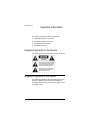
Graphical Symbols on the Device
The following information has been placed on the device:
Graphical Symbols in this Guide
The following symbols and their descriptions draw your
attention to important safe practices and additional
information that can help you avoid injury, death, or loss
of material or time.
1
WARNING! This indicates a potentially hazardous
situation that, if not avoided, may result in death or
serious injury. DO NOT IGNORE A WARNING!
CAUTION! This indicates a potentially hazardous
situation that, if not avoided, may result in minor or
moderate injury. DO NOT IGNORE A CAUTION!
IMPORTANT! This indicates information that will help
you avoid damage to your equipment, loss of materials, or
loss of time. PAY ATTENTION TO THESE
IMPORTANT STATEMENTS!
NOTE: This indicates a note about related information
on the current topic.
TIP: This indicates a tip that might save you time or
effort.
Important Safety Instructions
1. Read these instructions.
2. Keep these instructions.
3. Heed all warnings.
4. Follow all instructions.
5. Do not use this apparatus near water.
6. Clean only with dry cloth.
7. Do not block any ventilation openings. Install in
accordance with the manufacturer’s instructions.
2
8. Do not install near any heat sources such as
radiators, heat registers, stoves, or other apparatus
(including amplifiers) that produce heat.
9. Do not defeat the safety purpose of the polarized or
grounding-type plug. A polarized plug has two blades
with one wider than the other. A grounding type plug
has two blades and a third grounding prong. The
wide blade or the third prong are provided for your
safety. If the provided plug does not fit into your
outlet, consult an electrician for replacement of the
obsolete outlet.
10. Protect the power cord from being walked on or
pinched particularly at plugs, convenience
receptacles, and the point where they exit from the
apparatus.
11. Only use attachments/accessories specified by the
manufacturer.
12. Unplug this apparatus during lighting storms or when
unused for long periods of time.
13. Refer all servicing to qualified service personnel.
Servicing is required when the apparatus has been
damaged in any way, such as power-supply cord or
plug is damaged, liquid has been spilled or objects
have fallen into the apparatus, the apparatus has
been exposed to rain or moisture, does not operate
normally, or has been dropped.
14. This apparatus has no AC mains power switch. The
appliance coupler is the AC mains disconnect device.
As such, the appliance coupler must remain readily
operable; that is, it must be readily accessible, and
operation of the disconnect device must be free from
obstruction.
WARNING! To reduce the risk of fire or electrical shock,
do not expose this apparatus to rain or moisture.
3
WARNING! This CLASS I apparatus must be
connected to an AC mains socket outlet that has a
protective earthing connection (i.e., third-prong ground
conductor). DO NOT DEFEAT THE PROTECTIVE
EARTHING CONNECTION!
Additional Resources
The following resources are available to provide you with
additional support.
4
`
Your authorized Control4 reseller
`
Control4 Web Site: http://www.control4.com
`
Composer online help
`
Composer Media Edition online help
CHAPTER
1
Introduction to Media
Controller
This chapter introduces a Control4 home automation
system and explains the important role a Control4 Media
Controller plays in that system. It contains the following
information:
`
`
`
`
`
Role in a Control4 System
Features and Benefits
Requirements
What’s in the Box
Control4 Supported Devices
Role in a Control4 System
An essential component in every Control4 system is a
controller that acts as the central processor of the system.
Control4 controllers provide options for controlling lights,
home theaters, distributed audio systems, and other
devices controlled using various protocols, such as Infra
Red (IR), Serial, Contact, Relay, etc.
The Media Controller provides extensive media
management services for audio and video sources (such
as CDs, MP3 files, and DVDs). It has a large hard drive for
digital audio storage (such as imported CDs that have
been converted to MP3 files). It also allows you to use an
external storage device with USB support for media
storage.
During the importing process, the Media Controller
converts CDs to a compressed or non-compressed digital
format to provide convenient playback.
Once music has been imported to the Media Controller
hard drive, or other media has been stored in connected
devices, you can use the Media Controller to manage
5
your media collections, play music, or access other stored
media.
Features and Benefits
The Media Controller makes it easy to enjoy your favorite
music wherever you are. The Media Controller digitally
stores music collections and delivers simultaneous audio
streams over a wired or a wireless home network. The
Media Controller utilizes online music and movie
recognition. You can select music by artist, song, genre,
or even album cover art.
The Media Controller is the center of a complete home
automation system. It is also a platform to control lighting,
security, temperature and more throughout the home.
Music Server
6
`
Hard drive – Stores the entire family’s music
collections. The AVM-MC1-B has 80 GB of hard drive
space with room for approximately 1,000 CDs.
`
Multiple input options – Imports music using the
built-in CD Drive or a home network (wireless or
wired).
`
Multi-room audio – Distributes analog audio to three
separate zones.
`
Digital audio streaming – Provides digital audio
streaming throughout the home.
`
Catalog – Provides an entire digital music collection
to search by artist, genre, song, or album cover art.
`
Customized playlists – Easily creates playlists for
every occasion and mood.
Powerful Automation Controller
`
Complete theater control – Provides multiple IR
outputs and intelligent video sensing, making control
of the entire home theater easy.
`
Complete home control – Allows complete control of
the whole home using devices controlled by IR
contacts, relays, serial, IR, or other protocols.
`
Standards-based control – Devices throughout the
home are controlled via wired or wireless
communication (Ethernet or ZigBee 802.15.4 mesh
networking).
`
Seamless integration – Works with Control4 and a
comprehensive array of third party components.
Easy to Set Up
`
Easy configuration – Provides a software wizard on a
connected PC that guides users through the
installation process.
`
Connections made easy – Provides easy setup with
the included cables and clearly marked connectors on
the back panel.
Requirements
`
Wired Ethernet network in place, using a shielded
Ethernet cable to the Media Controller.
`
Media Controller measures 3 rack units high — 5.88”
with feet, standard rack width —17.24” with rack ears,
and 16.4” deep (this product).
`
System Remote Control and On-screen Navigation
(included).
`
A monitor or TV for on-screen navigation and control.
7
What’s in the Box
The following are included in your Media Controller box:
` Media Controller and On-screen Navigator
software
` Pluggable terminal block connectors (11)
` Control4 System Remote Control with LCD
Navigator display and 4 AAA batteries
` S-VIDEO cable
` Composite video cable
` IEC power cord
` IR emitters (8)
` Stereo RCA cable
` Media Controller Installation and User Guide
(this manual)
` On-Screen Navigator User Guide
` System Remote Control User Guide
This following sections include:
`
`
`
8
Front view with Door Opened
Backview
Specifications
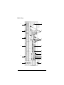
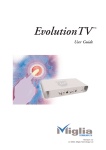
Front View with Door Opened
1. Front display area — For viewing settings, network addresses, playlist
and title sections, media information, receiver status, and system menus.
2. Buttons — For choosing options on the front display.
3. CD drive — For importing CDs into the system.
4. IR window — For capturing IR codes from third party devices from
hand-held devices, such as remote controls using the Driver Wizard
within Composer. The IR filter is designed to capture codes at or
close to 40 kHz.
5. Select Dial — For identifying the network address on the network
and for scrolling through menus and media lists on the front display.
6. USB port — For supported USB memory devices, such as FAT32
formatted devices, for storing MP3 files to utilize on the Control4
system.
7. Reset button — Resides behind the closed door for resetting the
Media Controller by holding the button for 10 seconds.
9
10
7
1
8
9 10
2
11
12
13
14
3
15
4
16
5
6
17
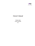
Back View
1. Serial 1- 2—Standard RS-232 serial ports with hardware flow
control available for controlling serial devices such as projectors or
DVD changers (DB9 connector type).
2. Contacts 1- 6—6 pin Pluggable Terminal Block connectors for up to
six dry contact closure, logic input connections, door contact
sensors, or motion sensors. Maximum voltage is 24 volt, AC or DC.
3. Relays 1- 6—6 pin Pluggable Terminal Block connectors for up to
six normally closed or normally opened switchable connections such
as blinds, fireplaces, or projector screens.
4. IR In 1- 4—Pluggable Terminal Block connectors provide support for
up to four hand-held IR devices, such as remote controls.
5. IR Out 1- 8—3.5 mm jacks for up to 8 IR output sensors. There are
two IR output types:
----IR outputs 1-4 are lower power (~10 ma)
----IR outputs 5-8 are higher power (~25 ma)
6. Video Sense Loop In-Out (pairs) 1-4—Composite port pairs for up
to four video sources, such as DVD players or VCRs, that allow the
system to determine the On/Off status of devices.
7. Serial 3- 4—9 pin Pluggable Terminal Block connectors for
configurable serial ports: RS-232, RS-422, or RS-485 for projectors
or other serial devices.
8. Ethernet—RJ-45 for a 10/100 BaseT Ethernet connection, using a
shielded Ethernet cable.
9. USB—Port to support external storage devices, such as USB
memory devices. Note: this is upside-down by most standards.
10. Modem—RJ-11 port for modem (currently disabled).
11. Digital Audio In—Optical connection (Toslink) for digital audio input.
12. Digital Audio Out—Optical connection (Toslink) for digital audio
output.
13. Audio In (Left-Right pairs) 1-3—RCA jack for stereo channel input
for up to three stereo analog sources.
14. Audio Out (Left-Right pairs) 1-3—RCA jack for stereo channel
line output for amplifiers or audio switches.
15. Video Out Options—VGA, Component, Composite or S-VIDEO
port for displaying navigation menus on a monitor or TV.
16. EZ ID™ Led’s—Every port on the Media Controller back panel is
supported by EZ ID Led’s that light at different times during the setup
process to identify ports and indicate signal activity.
17. Power plug port—IEC power cord.
11
Specifications
Model Numbers
AVM-MC1-B
Media Recognition
Connections
Audio Input: 3 analog, 1 digital
Audio Output: 3 analog, 1 digital
On-screen display output:
S-VIDEO, Composite, VGA,
Component
Video sense loop: 4 inputs and 4
outputs
AMG online CD/DVD recognition
and media information service
Audio Recording Formats
MP3: 192kbps
Audio Playback Formats
Uncompressed WAV and PCM:
44.1kHz, 16 bit stereo
MP3: 32kbps to 320kbps, CBR and
VBR
Serial: 2 RS232, DB9 connectors 2 Display
RS232 3-wire, RS422 or RS485,
Backlit LCD display
pluggable terminal blocks
Power Requirements
Contact: 6 Inputs, pluggable
100-120 / 200-240 VAC,
terminal blocks
60/50 Hz, 7/4 A
Relay: 6 outputs, normally closed
Dimensions
or normally open, pluggable
terminal blocks
H x W x D: 5.2” x 17” x 15.9” (or
IR: 4 inputs, 3-wire, pluggable
terminal blocks 8 outputs, 3.5mm
phone jacks
ZigBee (802.15.4 mesh networking
Ethernet 10/100baseT, RJ-45 jack
Modem: Disabled
USB: 1 front, 1 rear
Storage Capacity
80 GB hard drive
Approximately 1,000 CDs in
192kbps compressed MP3 format
12
132mm x 432mm x 404mm)
Weight: 17.5 lbs. (or 7.95 kg)
Shipping Weight: 23 lbs. (or 10.44
kg)
Control4 Supported Devices
For a list of Control4 supported devices and solutions, see
“Products” at http:/www.control4.com.
Typical devices include:
Speaker Point™
Wireless Dimmer
Mini Touch Screen
Wireless Switch
Touch Screen – 10.5”
Wireless 2, 3, & 6 Button
Keypads
Multi Channel Amplifier
Audio Matrix Switch
Wireless Thermostat
Wireless Outlet Dimmer
Wireless Outlet Switch
Wireless LCD Keypad
13
14
CHAPTER
2
Install the System
This chapter explains how to set up the Control4 home
automation system and how to make hardware connections.
The essential tasks include:
1.
Plan the Equipment Layout
2.
Power Up the Media Controller
3.
Connect to the Network
4.
Connect Devices
5.
Change Front Panel Information
Plan the Equipment Layout
When planning the equipment layout, follow these guidelines:
`
`
`
`
Plan Control4 System Connections
Meet Home Network Requirements
Plan Your System Connections
Determine Best Video Option
Plan Control4 System Connections
When setting up the Media Controller, you need to plan your
physical connections and within Composer define these
connections to mirror the actual connections.
For instructions on setting up the connections, refer to the
Composer Professional online help.
Meet Home Network Requirements
Ensure that your home network is in place before starting
your system setup. The Media Controller requires an Ethernet
connection in order to use all features as designed. When
connected, the Media Controller can access Web-based
media databases and can easily access Control4 system
updates.
15
Plan Your System Connections
When setting up the Media Controller, you need to plan the
physical connections. Then, at your preference you can either
use Interviewer (within Composer) to guide you through
setting up these connections, or you can set up the physical
connections first and then run Interviewer to tell the system
how things are physically connected.
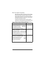
Complete the worksheet that follows to plan the system
connections. For more information, see the Composer online
help topic “Set up and Design a System with Interviewer.”
Table 2-1. Media Controller Connection Worksheet
Connection Options and Typical Use
Reserved for:
Serial 1-2 — Standard RS-232
serial ports with hardware flow
control available for controlling
serial devices such as projectors
or DVD changers (DB9 connector type).
1.
Serial 3-4 — 9 pin Pluggable
Terminal Block connectors
for configurable serial ports:
RS-232, RS-422, or RS-485
for projectors or other serial
devices. See “Configure and Connect to the Serial
Ports” on page 24 for more information.
1.
Contacts 1-6 — 6 pin Pluggable Terminal
Block connectors for up to six dry contact
closure, logic input connections, door
switches, or motion sensors. See
“Connect to the Contact Ports” on
page 26 for more information.
1.
2.
2.
2.
3.
4.
5.
6.
16
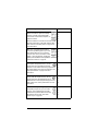
Connection Options and Typical Use
Reserved for:
Relays 1-6 — 6 pin Pluggable Terminal
Block connectors for up to six normally
closed or normally opened switchable
connections such as blinds, fireplaces, or
projector screens.
1.
Each set contains a connection for Common (COM)
Normally Closed (NC) or Normally Opened (NO).
See “Connect to the Relay Ports” on page 27 for
more information.
5.
IR In 1-4 — Pluggable Terminal Block
connectors provide support for up to four
hand-held IR devices, such as remote
controls. Each set of connections include
Power (+12v), Signal (SIG), and Ground
(GND). See “Add IR Receiver Capabilities
to Remote Locations” on page 27.
1.
IR Out: Low — 3.5 mm jacks for up to four
lower power IR outputs sensors (~10 ma).
These ports are for applications that may
experience cross talk or bleed through problems of
IR signals between two pieces of equipment. See
“Set Up IR Emitters” on page 28 for more
information.
1.
IR Out: High — 3.5 mm jacks for up to four
higher power IR outputs sensors (~25 ma).
These ports are for applications that require
additional drive current (brighter IR light) to the IR
LED emitters. See “Set Up IR Emitters” for more
information.
5.
Video Sense Loop In-Out (pairs) 1-4 —
Composite port pairs for up to four video
sources, such as DVD players or VCRs,
that allow the system to determine the On/
Off status of devices. See “Use Video
Sense Loops” on page 28.
1.
2.
3.
4.
6.
2.
3.
4.
2.
3.
4.
6.
7.
8.
2.
3.
4.
17
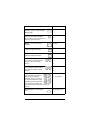
Connection Options and Typical Use
Reserved for:
Ethernet — RJ-45 for a 10/100 BaseT
Ethernet connection, using a shielded
Ethernet cable.
1.
USB — For supported USB memory
devices (such as FAT32 formatted
devices). One is on the back and one is
on the front (behind the door).
1.
2.
Modem — RJ-11 port (currently
disabled).
Disabled
Digital Audio In — Optical connection
(Toslink) for digital audio input.
In:
Digital Audio Out — Optical connection
(Toslink) for digital audio output.
Out:
Audio In (Left-Right pairs)
1-3 — RCA jack for stereo channel
input for up to 3 stereo analog
sources.
1.
Audio Out (Left-Right pairs)
1-3 — RCA jack for stereo channel
line output for amplifiers or audio
switches.
1.
Video Out Options —
VGA, Component, Composite or
S-Video port for displaying
navigation menus on a monitor or
TV. Second simultaneous outputs
available only if using combination
of Composite and S-VIDEO. See
See “Video Out Options Ranked by Quality” on
page 19.
1.
Power plug port — For IEC power
cord.
18
2.
3.
2.
3.
2. (Conditional)
For IEC power cord
Determine Best Video Option
If you have multiple connection options for a video
component, you need to determine the best connection
available. Table 2-2 provides a list of video connection
options that are ranked according to quality of video
performance.
NOTE: There are four Video Out format options
available on the Media Controller: VGA, Component,
Composite, and S-VIDEO. Only the combination of
S-Video and Composite can be used simultaneously.
Table 2-2. Video Out Options Ranked by Quality
Rank
Port
1
VGA
2
Component
3
S-Video
4
Composite
Connect to the Network
If you are using an Ethernet connection for the Media
Controller, plug the data cable from the home network
connection into the Media Controller RJ-45 port (labeled
“Ethernet”) and into the network port on the wall or at the
network switch.
19
Power Up the Media Controller
Plug the Media Controller power cord (provided) into an
electrical outlet.
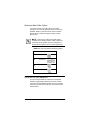
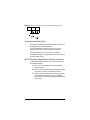
Change Front Panel Information
To view or change the system configuration:
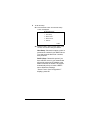
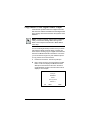
1. On the front panel, press the SETUP button. The
System Configuration screen plays:
SYSTEM CONFIGURATION
Host setme
DHCP Client
IP xx.xx.xx.xxx
MSK 255.255.0.0
MAC 00:0F:FF:00:01:30
EDIT
LCD
CANC
The menu options are:
EDIT: Press this to change the network setup.
LCD: Press this to set Brightness or Contrast
preferences for the LCD.
CANC: Press this to exit the screen without making
changes and return to the default system screen.
NOTE: The default configuration is DHCP Client. This
default setting assumes that your network system has a
device serving as the DHCP Server, such as a network
gateway, switch, or router. If there is not a DHCP server
in the network, you will need to choose another option.
20
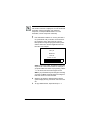
2. To edit the setup:
2a. Press the EDIT button. The Network Setup
screen is displayed:
NETWORK SETUP
1. Host Setup
2. DHCP Client
3. DHCP Server
4. Static IP
CANC
2b. Rotate the dial to select a setup option, press
the dial, then edit the settings as follows.
Host Setup: Choose this option to enter a
name server number for your DHCP Server.
Turn and press the dial to set a number,
then press OK.
DHCP Client: Choose this option if you
have a DHCP server in your network that
will provide a dynamic IP address to the
Media Controller as needed. The system
automatically will try to locate a DHCP
server. When the message
“Server Found. Save Configuration?”
displays, press OK.
21
DHCP Server: If the network does not have
a device serving as the DHCP Server (such
as a network gateway, switch, or router),
then you may use the Media Controller as
the DHCP server. The following screen with
default settings is displayed. These will
work for most Control4 system users.
DHCP SERVER SETUP
IP
10.
4.
4.
1
MSK
255.
255.
0.
0
GWY
.
.
.
BEG
10.
4.
4.
10
END
10.
4.
4.
100
OK
CANC
Static IP: Choose this option if you do not
plan to use a DHCP solution. If you choose
this option, you must provide an IP address,
Mask (MSK), and Gateway (GWY) number.
STATIC IP SETUP
IP
10.
4.
4.
1
MSK
255.
255.
0.
0
GWY
.
.
.
OK
CANC
3. To set LCD display preferences:
3a. Press the LCD button on the front panel. The
LCD Setup screen is displayed.
3b. Rotate the dial to select Brightness or Contrast
and then press the dial.
3c. Rotate the dial to adjust the setting and then
press the OK button.
4. Press the OK button to exit LCD Setup.
22
Connect Devices
You can use Interviewer within the Composer software on a
PC to walk you through the connection physical process or
you can set up the physical connections and then run
Interviewer to tell the Control4 system the applicable
connections.
Connect all applicable devices to the Media Controller using
one of the available connection methods, including those
described in Table 2-1,See “Media Controller Connection
Worksheet” on page 16..
The following sections contain additional information that may
be helpful during the setup process:
`
`
`
`
`
`
Use Pluggable Terminal Block Connectors
Configure and Connect to the Serial Ports
Connect to the Relay Ports
Add IR Receiver Capabilities to Remote Locations
Set Up IR Emitters
Use Video Sense Loops
Use Pluggable Terminal Block Connectors
Many Media Controller connections, including serial ports 3
and 4, contacts and relays, make use of pluggable terminal
block connectors—a removable plastic part with locking
latches for individual wires. The Media Controller ships with
one pluggable terminal block connector for every applicable
port.
To connect a device to a Pluggable Terminal Block:
1. Insert one of the wires required for your device into
the appropriate opening in the Pluggable Terminal
Block you reserved for that device (refer to Table 2-1
on page 16). For example, if you were adding a
motion sensor, you would connect the motion sensor
power input to +12V, its ground connector GND, and
its output signal to SIG. See the sections that follow
for instructions on connecting various protocols.
23
2. Lower the opening’s latch until it locks the wire in
place.
3. Repeat Steps 1-2 for all wires required for your
device.
NOTE: When you connect dry contact closure devices,
such as door switches, connect the switch between +12V
(Power) and SIG (Signal). See Contacts on Table 2-1.
Configure and Connect to the Serial Ports
The Media Controller provides four serial ports: Two that use
standard male DB9 connector and two that are configurable
as RS-232, RS-422, or RS-485 and provide hardware
handshake.
Wiring to one of the configurable ports depends on the wiring
requirements of the device you are connecting. Refer to your
device’s documentation and the following table and figures to
determine how to wire the port. Refer also to “Use Pluggable
Terminal Block Connectors” on page 23.
Table 2-3. Serial Port Configuration Options
Connector Type Transmit
Receive
Ground
RS-232
TX
RX
GND
RS-422
TX+TX-
RX+ RX-
RS-485
TX+ RX+
TX- RX-
24
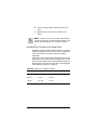
Figure 2-1.
Configure RS-232 for Configurable Port
TX
RTS
DB9 Pin #2
RX
CTS
RX+
RX-
TX-
TX+
DB9 Pin #3
GND
DB9 Pin #5
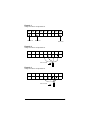
Figure 2-2.
Configure RS-422 for Configurable Port
TX
RTS
RX
CTS
RX+
RX-
TX-
TX+
GND
RX-
TX-
TX+
GND
CAT 3 or CAT 5
Figure 2-3.
Configure RS-485 for Configurable Port
TX
RTS
RX
CTS
RX+
CAT 3 or CAT 5
25
TIP: If you are having trouble communicating with
your device, make sure you have connected the
transmit and receiver wires correctly. Ensure that
the transmit line of the Media Controller is hooked to
the receiver line of the device, and that the receiver
line of the Media Controller is hooked to the transmit
line. Also, ensure that ground is hooked to the
ground.
Connect to the Contact Ports
The Media Controller provides six contact input ports.
See the following figures to determine how to connect the
device to a contact port. The maximum input voltage is 24 V
AC/DC.
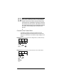
Figure 2-4. Connect Contact Port for Voltage Source (i.e. Motion Sensor)
12V
SIG
Provides
power for
Signal
small
devices Input
GND
Return
Path
Figure 2-5. Connect Contact for Dry Contact (i.e. Door Contact Sensor.
12V
SIG
Provides
power
back to Signal
Input
signal
input when
dry contact
closes
26
GND
Return
Path
Figure 2-6. Connect Contact for Self Powered Voltage Source Device
12V
SIG
Signal
Input
GND
Return
Path
Connect to the Relay Ports
The Media Controller provides one relay port as a subset of
the pluggable terminal block provided.
For most applications, attach one wire to the common
terminal and the other to the normally open terminal.
The relay switches close when the relay is activated.
The Media Controller can support applications that require a
normally closed contact.
Add IR Receiver Capabilities to Remote Locations
To add an IR-controlled receiver from a remote location to
your Media Controller:
1. Place your IR-controlled receiver at the remote
location needed.
2. Run the wires from the remotely located IR-controlled
receivers to the back of the Media Controller.
3. Connect the IR-controlled receiver wires (generally
power, signal, and ground) to one of the Media
Controller IR In connectors (pluggable terminal block
connectors).
27
Set Up IR Emitters
Your system might contain third-party products that are
controlled with IR commands (usually through remote
controls). To provide a way for the Media Controller to control
a device that only recognizes IR commands, complete the
following setup.
1. Plug the 3.5 mm connector end of one of the 8 IR
stick-on emitters provided into an IR Out port on the
Media Controller.
2. Place the stick-on emitter end over the IR receiver on
the media player, TV, or other target device to
transmit IR signals from the Media Controller to the
target.
Use Video Sense Loops
Video sensing can enhance the ability to sense the power
state of a device, such as whether the device is “on” or “off.”
If you need to add video signal sensing capabilities for a video
device (such as a TV, VCR, DVD player, etc.), connect one of
the device’s composite Video Out ports to a Media Controller
Video Sense In port. Then, use the companion Video Sense
Out port (where available) for the device’s video out as
needed.
For Video Sense only (no loop-through), connect a device’s
Composite Video Out port to one of the two Video Sense In
ports.
28
CHAPTER
3
Configure the System
The Composer interface and wizards are designed to help
you simplify the process to fully design, set up, and
program a Control4 system.
This chapter provides an introduction for how you can
configure a Control4 system using the Composer
software. The essential steps include:
1.
Design and Setup the System
2.
Set Up Media and Create Playlists
3.
Program the Home Automation System
For more detailed instructions and information, refer to the
Composer online help.
Design and Setup the System
Within Composer, there are two options that allow you to
design and set up Control4 systems, including:
`
`
Interviewer
The Main Composer Interface
TIP: You can go back and forth between the Interviewer
and Composer at any time during setup or at any time for
maintenance of the system after the initial setup.
29
Interviewer
The Home Automation Interviewer (Interviewer) is a
wizard that guides you through project configuration to set
up the Control4 system.
To launch Interviewer within Composer, from the File
menu, click Run Interview.
If it is your first time setting up a Control4 system or you
want to ensure you think of all the setup options, use the
Interviewer.
As you answer questions while going through Interviewer,
it configures a project. It takes you through successful
completion of setting up a project covering required setup
steps for adding devices and making connections.
Interviewer includes the following set up process:
30
`
System Design helps you define your project
information and the types of devices on the system.
`
Rooms helps you identify the rooms in your project
and each device in a given room.
`
Network helps you identify all the network
connections. Network connections are devices that
connect to the controller hardware using a network
address. These include devices like Control4
Dimmers, Switches, Keypads, Mini Touch Screens,
System Remote Controls, and any other device that
communicates ZigBee or TCP/IP.
`
Audio/Video helps you define all the audio/video
connections on the system. Audio/video connections
include any device’s inputs and outputs that carry
audio and/or video signals.
`
Control helps you define all the control connections
on the system. Control connections include devices
that use relay, contacts, IR, or serial for control.
Interviewer does not include media setup or programming
of devices or agents. For more information and example
implementations, see the Composer online help.
The Main Composer Interface
The main Composer interface allows you to set up and
program a Control4 system. Within Composer, you can
add devices, make connections, set up media, and
program using devices and agents.
31
Setting up with Composer, you have the flexibility to follow
any set up path you desire. When you become familiar
with the Control4 system, this is the quickest method for
setting up a system. When designing, setting up, and
making connections for a project, you will use the
following Composer views:
`
System Design View — Allows you to build the Project
Tree and identify the devices on the system.
`
Connection View — Allows you to identify all
connections (Room, Control, AV, Network).
For more information and example implementations, see
the Composer online help.
Set Up Media and Create Playlists
To use the supported Media Management features, you
need to have access to the media from either an external
storage device or other stored or broadcast media
available from other devices—such as a PC, disc
changer, tuner, or network. To set up an external storage
device, see the online help topic: “Use External Storage
Devices.”
To set up Media or create playlists on the system, you can
use Composer Media Edition or the Media view within the
Composer Professional Edition. For more information,
see the online help topic: “Set up Media and Create
Playlists.” For more information, see the online help topic:
“Set up Media and Create Playlists.”
You can also create custom playlists from the navigation
devices, such as On-screen Navigator (display monitor),
Mini Touch Screen, and Wireless Touch Screen. For more
information, see the documentation provided with your
navigation device.
32
Program the Home Automation System
The programming of the system includes
programming interactions between events on the
system and actions of other devices. You can program
the behavior of devices, such as when the projector is
turned on, the motorized screen comes down or when
the door is opened, the lights turn on.
To do programming on the system using the
Composer, drag and drop events and actions for
corresponding devices on to a programming script.
For more information, see the Composer online help.
33
34
CHAPTER
4
Use Media Controller
This chapter introduces interfaces and the common
system tasks you can perform with the Media Controller.
It contains the following information:
`
`
`
Control Devices and Use the System
Set up and Use External Storage Device
Copy Music to the Digital Audio Player
Control Devices and Use the System
Once the Media Controller is set up, any navigation
device associated with it (such as a Mini Touch Screen or
a System Remote Control) is dynamically maintained.
Any change made to the system is automatically reflected
on all navigation devices. These options include roomspecific menus and controls.
The following user interfaces are included with the Media
Controller:
`
`
`
Media Controller Front Display
On-Screen Navigator
System Remote Control with LCD
Additional user interfaces ship with other navigation
devices and are described in the documentation that
ships with them.
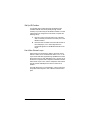
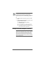
Media Controller Front Display
The information that displays on the Media Controller front
display depends on the action you choose with the front
panel buttons or with some other system navigation
35
device. See“Change Front Panel Information” on page 20
Control4
Fri, Apr 15 11:06:30
EJCT
CLOSE
SETUP
for more information.
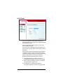
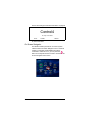
On-Screen Navigator
The Media Controller provides an on-screen system
called Control4 On-Screen Navigator. Once a Control4
system is configured and the Media Controller is
connected to a monitor or TV, you can press the
button on the System Remote Control to access the OnScreen Navigator home screen.
36
The On-Screen Navigator Home screen displays the
current location and provides access to other locations
and all subsystems.
`
Location (upper-left of screen): Displays current room
name that provides access to all available rooms in
the system when you click on it.
`
Radio: Allows you to browse all radio stations
available or just favorite stations. Play an AM, FM.
XM, Sirius, Satellite or Cable DMX, and radio
broadcast.
`
Music: Allows you to browse all stored music and filter
the collection by artist, genre, or alphabetically. Also,
provides on-screen controls for the Digital Audio
Player—the built-in device that plays the digital audio
files stored in the Media Controller.
`
TV: Allows you to browse all broadcast channels
(UHF/VHF, cable or satellite), then choose a channel.
`
Videos: Allows you to view all available videos (or
stored movies) and to control DVD players, VCRs, or
DVRs.
`
Comfort: Allows you to control all comfort-related
devices, such as fans, curtains, blinds, or fireplaces.
`
Lights: Provides controls for all lighting devices and
lighting scenes that are available in the current room.
`
House: Provides controls for security and
communication-related features. Currently displays
status information on contact switches (such as those
found on doors, windows, motion sensors, cameras,
and sprinklers).
`
Info: Displays information such as: network status,
screen savers, and other options.
For detailed information about using On-Screen
Navigator, refer to the On-Screen Navigator User Guide.
37
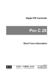
System Remote Control with LCD
The Control4 System
Remote Control that
ships with this product
includes an LCD for
system information and
feedback, in addition to
a variety of buttons for
accessing and
controlling system
components and
media. The information
that displays on the
remote control LCD
depends on the action
you choose with the remote control buttons and/or with
another system navigation device.
For detailed information on the remote control, refer to the
System Remote Control User Guide.
Set up and Use External Storage Device
When using the Media Controller as the primary controller
in the home, from the USB port (on the back), you can
store and access media from an external storage device,
such as a network hard drive or USB memory device.
For more information, see the Composer online help
topic: “Use External Storage Devices.”
38
Copy Music to the Digital Audio Player
Control4 audio systems make use of digital music files
that have been added to the Media Controller digital audio
player storage area and scanned into the system’s music
database.
NOTE: Control4 Composer software offers installers a
variety of methods for adding AND scanning music.
Refer to the Composer Professional or Media Edition
online help.
You can create digital backup versions of all your music
CDs using the Media Controller. When you back up a
music CD, the resulting copy is a digital music file that is
stored on the Media Controller’s hard drive. From there
you can access it through many user interface options.
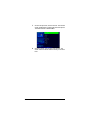
To copy a music CD to the hard drive:
1. Press the EJCT button. The CD tray will open.
2. Drop a music CD in the tray and press the CLOSE
button on the front display. The Media Controller
attempts to find a match for the CD in the online
media database provided. The first match found is
displayed. For example:
CD BACKUP
Kenny G
Breathless
Track 1
The Joy of Life
MATCH 1
OK
NEXT
CANC
39
NOTE: If the media database cannot identify the music
CD, the title “Unknown” is displayed. You can edit the CD
information using the Navigator user interfaces,
Composer, or Composer Media Edition. For more
information, see the Composer online help.
3. If the information in Match 1 is correct, press OK. If
not, press NEXT until you find the correct match or
the “Unknown” option, then press OK. The CD
backup will then begin and progress track-by-track
until the entire CD is saved in digital format to the
hard drive. For example:
CD BACKUP
Kenny G
Breathless
Track 02
Forever In Love
CANC
SKIP
CANC: If you press CANC, the backup process will
stop from the current track forward. For example, if
you press CANC when Track 3 is progressing, Tracks
1 - 2 are saved, but Track 3 and higher are not.
SKIP: If you press SKIP anytime during the recording
of a track, the Media Controller skips recording that
track and moves on to the next track.
4. When the CD backup is finished and the default
system display returns, press EJCT and remove the
CD.
5. To copy additional CDs, repeat the steps 2 - 4.
40
NOTE: If the message HARD DISK FULL displays, then
click OK and then click CANC to stop the backup
process. You will need to free up disk space on the Media
Controller before you can continue backing up CDs.
6. If you are finished copying CDs, press the CLOSE
button.
7. To free up disk space on the Media Controller, use the
Composer software interface:
7a. Start Composer and open this Media
Controller’s project.
7b. From the Media view, highlight Digital Audio.
7c. In the Album list, select one or more albums you
want to delete and then click Delete.
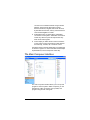
Change On-screen Navigator Themes
NOTE: The instructions in this manual are based on the
default theme, Radiant Blue. When you apply a different
theme, your process steps will deviate from the ones
documented in this manual. We recommend using the
manual to become familiar with the default user interface
before changing themes.
41
1. On the Info option bar, choose Themes. The Themes
screen is displayed, including a list of theme options.
The default theme is Radiant Blue.
2. Choose a theme, then choose Load Theme. The
screen will soon refresh with the theme you chose to
load.
42
CHAPTER
5
Warranty and Regulatory
Compliance
This chapter provides the following information:
` Warranty
` Regulatory Compliance
Warranty
This section provides the following information:
` Limited Hardware Warranty
` Hardware Warranty Terms
` Software Agreement
IMPORTANT! Warranty terms may be different with the
country of purchase; contact your Authorized Control4 Sales
and Service office for detailed product warranty information.
Limited Hardware Warranty
Control4 warrants its Media Controller product to be free from defects
in material and workmanship during the warranty period. If the Media
Controller proves to be defective in material or workmanship during the
warranty period, Control4 will, at its sole option, repair or replace the
product with a like product. The warranty extends only to products
purchased directly from an Authorized Control4 Dealer or Control4
Corporation.
Life of Warranty:
Control4 Media Controllers are warranted for one (1) year from the date
of the first consumer purchase.
What the warranty does not cover:
` Misuses; unauthorized modification; opening for any reason except
to perform an official upgrade using a proper tool/kit
43
` Operation or storage outside the environmental specifications for
the product
` In-transit damage and improper maintenance
` Physical damage to the unit, such as a cracked or broken screen or
defect resulting from use of improper software, accessories, media,
supplies, consumables, or such items not designed for use with the
product.
Hardware Warranty Terms
READ THESE WARRANTY TERMS CAREFULLY BEFORE
INSTALLING OR USING THE CONTROL4 SYSTEM OR
COMPONENTS. YOUR INSTALLATION AND USE OF THE SYSTEM
OR ANY OF ITS COMPONENTS INDICATES THAT YOU AGREE TO
BE BOUND BY THESE TERMS. IF YOU DO NOT AGREE TO ALL OF
THE TERMS OF THIS WARRANTY, RETURN THE PRODUCT TO
THE PLACE OF PURCHASE FOR A FULL REFUND.
ONE-YEAR LIMITED WARRANTY
1.
WARRANTY
Control4, Corporation. ("Control4") warrants that at the time of sale the
Media Controller (the “product”) will be free from defects in material and
manufacture and will conform to Control4's specifications for the
components. Control4 further warrants that for a period of 12 months
after sale the product will function in accordance with its specification,
PROVIDED THAT it is installed and maintained in accordance with
Control4's instructions and is not subjected to (a) alteration or
unauthorized repairs, (b) misuse or abuse, (c) Acts of God (including
without limitation hurricanes, tornadoes, floods, earthquakes, or other
severe weather or natural phenomena), or (d) improper storage or
handling or other treatment or installations for which it was not
intended. This warranty extends only to products purchased directly
from Control4 or an Authorized Control4 Dealer.
2.
DISCLAIMER OF OTHER WARRANTIES
The preceding warranties are the exclusive and sole express
warranties given by CONTROL4. They supersede any prior, contrary or
additional representations, whether oral or written. CONTROL4
HEREBY DISCLAIMS AND EXCLUDES ALL OTHER WARRANTIESWHETHER EXPRESS, IMPLIED, OR STATUTORY-INCLUDING ANY
ARISING FROM COURSE OF DEALING OR USAGE OF TRADE,
44
ANY WARRANTY OF MERCHANTABILITY AND ANY WARRANTY
OF FITNESS FOR A PARTICULAR PURPOSE, except that for product
purchased directly by a consumer, any implied warranties are limited in
duration to the term of the express warranties provided above.
Some states do not allow limitations on how long an implied warranty
lasts, so the above limitation may not apply to you.
3. EXCLUSIVE REMEDY FOR ANY
NONCONFORMITIES
If during the applicable Warranty Period, the product does not conform
to the preceding Warranties, the Owner shall notify Control4 as
provided below, and within a reasonable time Control4 will provide, at
its option, one of the following: (1) a replacement product for any
nonconforming or defective component (such replacement product
may be new or refurbished to be comparable in function and
performance to a new product) or (2) the price at which Control4 sold
the non-conforming product. In the event of repair or replacement,
there may be a loss of data in the memory of the product for which
warranty service is sought. Control4 will not provide, and will not be
liable for, labor, costs of removal or reinstallation of product, disposal,
freight, taxes, or other incidental charges.
THESE REMEDIES ARE THE EXCLUSIVE AND SOLE REMEDIES
FOR ANY BREACH OF WARRANTY.
For any breach of warranty, the Owner must notify Control4 in Section
7 below within thirty (30) days after discovering the nonconformity. The
notice must describe the location and nature of the nonconformity. The
owner must give Control4 a reasonable opportunity to the claimed
nonconformity before undertaking any repairs, removal or
replacement. All products returned to Control4 require a Return
Merchandise Authorization (RMA) number. The RMA number is
obtained from Control4 Customer Support Department. The RMA
number must be clearly marked on the outside of each box. The RMA
is valid for a 30-day period. After the 30-day period, the RMA will be
cancelled. Any shipments received not consistent with the RMA or after
the RMA is cancelled, will be refused. Control4 is not responsible for
products returned without a valid RMA number. Compliance with the
requirements of this paragraph is a condition to coverage under the
Warranty: If these requirements are not complied with, Control4 will
have no obligation to provide any remedy for any breach of warranty.
45
4. DISCLAIMER OF INCIDENTAL AND
CONSEQUENTIAL DAMAGES
IN NO EVENT SHALL CONTROL4 BE LIABLE FOR ANY
INCIDENTAL, SPECIAL, INDIRECT OR CONSEQUENTIAL
DAMAGES, WHETHER RESULTING FROM NONDELIVERY OR
FROM THE USE, MISUSE OR INABILITY TO USE THE PRODUCT
OR FROM DEFECTS IN THE PRODUCT OR FROM CONTROL4'S
OWN NEGLIGENCE. This exclusion applies even if the remedy
provided by Control4 fails of its essential purpose.
Some states do not allow the exclusion or limitation of incidental or
consequential damages, so the above limitation may not apply to you.
5.
APPLICABLE LAW
This Warranty will be interpreted, construed, and enforced in all
respects in accordance with the laws of the State of Utah, without
reference to its choice of law rules. The U.N. Convention on Contracts
for the International Sale of Goods will not apply to this Warranty.
6.
SEVERABILITY
If any provision of this warranty is found to be invalid or unenforceable,
then the remainder shall have full force and effect, and the invalid
provision shall be partially enforced to the maximum extent permitted
by law to effectuate the purpose of the agreement.
7.
ADDRESS FOR NOTICES TO CONTROL4
Control4 Corporation
11734 Election Road
Salt Lake City, UT 84020
http://www.control4.com/
This warranty gives you specific legal rights and you may also have
other rights which vary from State to State.
46
Software Agreement
The Control4 Media Controller contains pre-installed software. Please
read the following Control4 terms before proceeding:
NOTE: Carefully read this License Agreement and the
Limited Warranty statement before operating the equipment.
The rights to the software are licensed, not sold. Control4 or
its licensors continue to own all intellectual property rights to
the software, and you will be granted certain rights to use the
software upon your acceptance of this license. Rights in the
software are offered only on the condition that you agree to
all terms and conditions of the License Agreement.
Operating the equipment indicates your acceptance of these
terms and conditions. If you do not agree to the terms and
conditions of the License Agreement, return the complete
package for a full refund now.
Terms that Govern Software Use
You may only use the software as designed on the device on which it
comes pre-installed. You may not reverse, assemble, or decompile the
software.
Limited Software Warranty, Liability, and Remedy
IMPORTANT! This Control4 Software Limited Warranty
shall cover all software that is provided to you, the customer,
as part of the Control4 product, including any operation
system software.
The Remedies provided in this document are your sole and exclusive
remedies. In no event shall Control4 be liable for any direct, indirect,
special, incidental, or consequential damages (including lost profit),
whether based on warranty, contract, tort, or any other legal theory.
In no case shall Control4's liability exceed the purchase price for the
software and/or product. The limitations set forth above will apply
regardless of whether you accept the software.
47
Regulatory Compliance
North America
This product complies with standards established by the following
regulatory bodies:
Federal Communications Commission (FCC)
Industry Canada
Underwriters Laboratories Inc. (UL)
FCC
FCC ID: R33AVMMC11
This device complies with Part 15 of the FCC Rules. Operation is
subject to the following two conditions: (1) This device may not cause
harmful interference, and (2) this device must accept any interference
received, including interference that may cause undesired operation.
This equipment has been tested and found to comply with the limits for
a Class B digital device, pursuant to Part 15 of the FCC Rules. These
limits are designed to provide reasonable protection against harmful
interference in a residential installation. This equipment generates,
uses, and can radiate radio frequency energy and, if not installed and
used in accordance with the instructions, may cause harmful
interference to radio communications. However, there is no guarantee
that interference will not occur in a particular installation. If this
equipment does cause harmful interference to radio or television
reception, which can be determined by turning the equipment off and
on, the user is encouraged to try to correct the interference by one of
the following measures:
` Reorient or relocate the receiving antenna.
` Increase the separation between the equipment and receiver.
` Connect the equipment into an outlet on a circuit different from that
to which the receiver is connected.
` Consult the dealer or an experienced radio/TV technician for help.
IMPORTANT! Changes or modifications not expressly
approved by Control4 could void the user’s authority to
operate the equipment.
48
Industry Canada
This Class B digital apparatus complies with Canada ICES-003.
Cet appareil numérique de la classe B est conforme à la norme NMB003 du Canada.
Underwriters Laboratories Inc.
This product has been tested
by UL and has been found to
be in compliance with:
UL 60065:2003: Standard for
Audio, Video and Similar
Electronic Apparatus —
Safety Requirements
CAN/CSA-C22.2 No. 60065-03, First Edition
49
CE Declaration of Conformity
DeClaration OF CONFORMITY
Control4 Corporation, 11734 S. Election Road, Suite 200, Salt Lake City,
UT 84020-6432, Tel (801) 523-3100
Product: Media Controller, Model No: AVM-MC1-B
The undersigned hereby declares, on behalf of Control4 Corporation, that
the above-referenced product, to which this declaration relates, is in
conformity with the provisions of:
Council Directive 89/336/EEC (May 3, 1989) on Electromagnetic Compatibility
Council Directive 1999/5/EC (Mar 9, 1999) on Radio & Telecommunication Terminal
Equipment (R&TTE)
Council Directive 73/23/EEC (Feb 19, 1973) on Low Voltage Equipment Safety
Council Directive 93/68/EEC (Jul 22, 1993) Amending Directives 89/336/EEC and 73/23/EEC
and has been tested to the requirements of, and shown to be in compliance
with, the following requisite standards:
EMC
EN 301 489-1 V1.4.1 — Electromagnetic compatibility and Radio spectrum
Matters (ERM); ElectroMagnetic Compatibility (EMC) standard for radio
equipment and services–Part 1 Common technical requirements.
EN 301 489-17 V1.2.1 — Electromagnetic compatibility and Radio spectrum
Matters (ERM); ElectroMagnetic Compatibility (EMC) standard for radio
equipment and services; Part 17: Specific conditions for 2.4 GHz wideband
transmission systems and 5 GHz high performance RLAN equipment.
AS/NZS CISPR 22: 2002 — Information Technology Equipment – Radio
disturbance characteristics.
Radio
EN 300 328-2 V1.4.1 — Wide band transmission systems; data transmission
equipment operating in the 2.4GHz ISM band. Harmonised EN covering
essential requirements under Article 3(2) of the R&TTE Directive.
AS/NZS 4771: 2000 — Spread Spectrum Equipment using 900MHz, 2.4GHz and
5.8GHz bands.
Safety
IEC 60950-1: 2001 (1st Edition) and/or EN 60950-1: 2001 — Information
Technology Equipment—Safety with national and group differences in
accordance with CB Bulletin No. 109A December 2005: AS/NZS 60950-1: 2003.
The Technical Construction File required by these Directives is maintained
at the corporate headquarters of Control4, Salt Lake City, Utah, U.S.A.
Signed,
Paul E. Nagel—Vice President of Engineering, July 27, 2006
Recycling
For information on recycling, please go to www.control4.com/
recycling
50