1
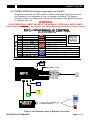
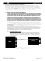
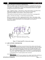
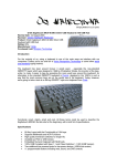
MFC-F (V Series)
INSTALLATION MANUAL
4/1/2006
/2006
MFC INSTALLATION MANUAL
Rev C, Issue 2
GENERATION III CAR CONTROL SYSTEMS
COPYRIGHT © 2006 Connect2Car, Inc. All rights reserved.
CONNECT2CAR.COM
Table of Contents
1.
INTRODUCTION ................................................................................................................... 3
1.1 Disclaimer ............................................................................................................ ………3
1.2 Copyright ................................................................................................................... 3
1.3 Safety Issues ............................................................................................................... 3
1.3.1 Recording And Saving The Installation Wiring Setup...................................................... 4
1.3.2 Simulation Mode For Recipes: ................................................................................ 4
1.3.3 Accessory Timeout Feature: .................................................................................. 4
1.3.4 Lost Connection Settings....................................................................................... 5
1.4 Technical Support......................................................................................................... 5
1.5 Glossary Of Terms And Abbreviations ................................................................................. 5
2.
SYSTEM OVERVIEW .............................................................................................................. 6
2.1 Possible Setups With The MFC .......................................................................................... 7
2.2 Phone Interface Setup.................................................................................................... 8
2.3 PDA Interface Setup ...................................................................................................... 9
2.4 PC Interface Setup ....................................................................................................... 10
3.
MFC
3.1
3.2
3.3
3.4
4.
COMMON INSTALLATION SETUP EXAMPLES WITH THE MFC............................................................14
4.1 Primary Car Control (Alarm Style With Remote Start) ............................................................ 14
4.2 Control Hydraulics(Another Unique Way To Use The MFC) ....................................................... 15
4.3 Control Hydraulics(Another Unique Way To Use The MFC) ....................................................... 16
5.
EXAMPLE ACCESSORY WIRING CONFIGURATIONS ........................................................................17
5.1 Remote Start Accessory Configuration ............................................................................... 17
5.1.1 Triggered Remote Start ....................................................................................... 17
5.1.2 Direct Remote Start ....................................................................................... 18-20
5.2 Door Lock/Unlock Accessory Configuration ......................................................................... 21
5.3 More Accessory Configurations ........................................................................................ 21
5.3.1 Parking Lights: .................................................................................................. 21
5.3.2 Radio Turn On: ................................................................................................. 22
5.3.3 Heater And Climate Controls:................................................................................ 22
5.3.4 Power Windows/Sunroof: ..................................................................................... 22
5.3.5 Trunk Release:.................................................................................................. 22
5.3.6 Air Ride Suspension: ........................................................................................... 22
5.4 The Sky Is The Limit: .................................................................................................... 22
FEATURES ..................................................................................................................11
General Features: ........................................................................................................ 11
Detailed Specifications:................................................................................................. 11
General Wiring Harness Configuration: .............................................................................. 11
Connector And Wiring Details.......................................................................................... 12
3.4.1 Main Harness Connector P1................................................................................... 12
3.4.2 Bluetooth Antenna Connection .............................................................................. 12
3.4.3 Serial Data Connector ......................................................................................... 13
3.4.4 PDA/Phone USB Chargers ..................................................................................... 13
3.4.5 Power And Serial Data LED Indicator ....................................................................... 13
3.4.6 Bluetooth LED Indicator....................................................................................... 13
MFC INSTALLATION MANUAL
Page 1 of 22
CONNECT2CAR.COM
Table of Figures
Figure 1: Overall MFC Capability ........................................................................... 7
Figure 2: POSSIBLE PHONE INTERFACE CONFIGURATIONS ............................................... 8
Figure 3: POSSIBLE PDA DEVICE CONFIGURATIONS ....................................................... 8
Figure 4: POSSIBLE PC/CARPC CONFIGURATIONS......................................................... 9
Figure 5: MFC CONNECTOR DIAGRAM...................................................................... 10
Figure 6: Main Connector (P) Detail ....................................................................... 12
Figure 7: MFC Example: Simple setup..................................................................... 14
Figure 8: Direct MFC Example: Setup with Alarm add-on .............................................. 15
Figure 9: MFC Example: Setup as Hydraulics Controller ............................................... 16
Figure 10: Triggered Remote Start ........................................................................ 17
Figure 11: Direct Remote Start ............................................................................ 18
Figure 12: Ignition Key Positions........................................................................... 20
Figure 13: Connecting MFC to factory door triggers .................................................... 21
MFC INSTALLATION MANUAL
Page 2 of 22
CONNECT2CAR.COM
1.
INTRODUCTION
This document describes the installation outline and detail for the Connect2Car MFC also
known as the Multi Function Controller Module is designed to provide multi-purpose
solutions for real-time control and management of vehicle accessories. The Multi
Functional Controller is a new type of flexible dynamic controller system geared
specifically towards car accessory management. The heart of the MFC unit lies in the
flexible user configurable software management and control system. Using a cell phone,
PDA or CarPC Computer system, the user or installer can specifically control any accessory
in any manner they wish, or use known preconfigured packages. Using the selected
configuration packages, the controller device (phone, PDA e.g.) establishes a two-way
communication with the hardware unit in the vehicle, and provides the user with virtual
dashboard of their controls of interest, based on their configurations. Furthermore, the
rich user interface skins also provide a more customized experience and local
personalization to taste.
1.1 Disclaimer
The information contained in this document is accurate at time of release. However,
as Connect2Car Inc, is committed to continued research and development activities,
these specifications may change from time to time.
The present manual by Connect2Car Inc reflects the present state of the art of the
products described therein. We have endeavored to give a description that is as
complete and clear as possible in order to make work with our products as easy as
possible for you. All the same, the manual may contain technical inaccuracies and
typing errors. As a result of the rapid advance in the art, we must also reserve the
right to incorporate technical alterations and developments without separate advance
notice.
That is why Connect2Car Inc, does not give any warranty for the contents of the
manual and for its continuing applicability. Nor is Connect2Car Inc. liable for any loss
that might result from consultation of this manual. Particularly, Connect2Car Inc is
not liable for damage, nor indirect damage (including damage caused by financial
loss, and similar consequences), arising from the use or improper use of this manual,
not even in the case where it was pointed out to Connect2Car Inc. or an agent of
Connect2Car Inc. that such damage might be sustained.
Contact your Connect2Car representative, should you require clarification on
information contained in this document or to request of copy of the latest version of
this document. You can also visit www.connect2car.com for all the latest
information/product manuals and documentation.
1.2 Copyright
The Connect2Car MFC Installation Manual is copyright by Connect2Car Inc. with all
rights reserved. No part of this manual may be reproduced in any form without the
prior written approval of Connect2Car Inc.
1.3 Safety Issues
It is recommended that you read these simple guidelines carefully before use, to
ensure the safe operation of the module. The MFC should be installed by a
professional automotive electronics installer.
The fact that there is unlimited control through the SOFTDASH interface software
could give rise to one putting the accessories in and unconditional or dangerous state.
MFC INSTALLATION MANUAL
Page 3 of 22
CONNECT2CAR.COM
(e.g. cranking the ignition of a manual transmission vehicle in gear, controlling
moving parts without caution, e.g. window, door poppers, hydraulics, linear
actuators, etc…) Because of this unforeseen multi-functionality, Connect2Car, Inc.
CANNOT VALIDATE NOR ENSURE THAT ANY OR ALL SAFETY REQUIREMENTS ARE MET
DURING INSTALLATION AND THEREFORE ACCEPTS NO RESPONSIBILTY FOR THE
INSTALLATION OR LOSS CAUSED BY THE INSTALLATION OR USE OF THE MFC MODULE
AND THE SOFTDASH INTERFACE.
Below are outlined safety features implemented in the MFC to minimize risk of
damage or unwanted use or control of an accessory with the MFC.
1.3.1 RECORDING AND SAVING THE INSTALLATION WIRING SETUP
The first thing you “user or installer” should do during installation is to label
the installation wiring in the SOFTDASH “Installer Wiring” menu. This
automatically uses this information to remind you of accessory configuration
mismatches. This also serves as a good reference point if you were to change
that accessory control in the future. Most times when people go to a different
installer to install or change some wiring in their vehicles, the installer
completely rips out and rejects the old wiring because it wasn’t done by them,
and charges for a totally new job. The main reason being that they do not want
to start retracing or following somebody else’s wiring. Sometimes the previous
job might be obviously bad. However, this installer menu helps to share this
installation data between old and new installers. You can input detailed
information about the wire, its color, type, comments on its usage/connection
etc. This helps to refresh things later, and also it is used to remind you when
changing controls in the SOFTDASH interface.
1.3.2 SIMULATION MODE FOR RECIPES:
If you are going to be configuring or trying out a custom recipe that is not
endorsed by Connect2Car, make sure you test it out in the software simulation
mode and observe and make sure the output effects on the accessory
indicators are what you expect. If you are not sure, consult your installer to
verify or test the Recipe, based on your current car Installation/configuration.
ALSO MAKE SURE TO CHECK THE ACCESSORY SETTINGS OF EACH RECIPE BEFORE
YOU USE THEM. THE ACCESSORY SETTING IN THE RECIPE HAS TO MATCH THE
SAME ACCESSORY LOCATION INSTALLED IN YOUR VECHILE. E.g. using a recipe
from somebody that runs a door controller accessory on ACC 1, might do
something else in your car if a different accessory is installed on ACC 1 in your
car. You will have to check your installation wiring diagram to make sure ACC 1
in your car runs the door lock control, or map it to the correct accessory
output.
1.3.3 ACCESSORY TIMEOUT FEATURE:
The accessory timeout feature forces the MFC unit to turn off any given
accessory, based on its timeout setting. This is to safeguard against unwanted
effects that can be caused by accidentally trying out or unexpectedly using an
unknown or badly configured Recipe (Accessory control configuration setting).
Before you try out or activate any recipes, make sure you configure the safety
timeout settings of each of the MFC accessory outputs. The time out settings
should reflect a realistic timeout of the maximum safe time that accessory
should be activated. Default setting is 5 seconds for all the accessory outputs.
MFC INSTALLATION MANUAL
Page 4 of 22
CONNECT2CAR.COM
It is also recommended that you use very short timeouts for accessories that
control electro-mechanical devices or features e.g. ignition, windows, sunroof,
linear actuators etc.
1.3.4 LOST CONNECTION SETTINGS
The SOFTDASH interface by default will automatically turn off all the accessory
outputs once the user control device has been disconnected either via data
cable or is out of Bluetooth connection range. This setting can be over ridden
from the configuration settings. It can be configured per accessory and a [WAIT
FOR RECONNECT] time can be set so as to control how long the unit will wait
for the user before engaging into the safe mode. It is recommended that you
do not disable the safe mode for accessories that control electro-mechanical
devices or features e.g. ignition, windows, sunroof, linear actuators etc.
1.4 Technical Support
For all technical support please contact Connect2Car Inc. via
[email protected]. Your questions will be prioritized and responded to in a
professional and prompt manner. Please also check out the FAQ section on the
website at www.connect2car.com
1.5 GLOSSARY OF TERMS AND ABBREVIATIONS
ABBREVIATION
DESCRIPTION
MFC
MULTI-FUNCTION-CONTROLLER UNIT
OEM
ORIGINAL EQUIPMENT MANUFACTURER
GND
ELECTRICAL VOLTAGE GROUND REFERENCE POINT
PDA
PERSONAL DIGITAL ASSISTANT
FAQ
FAVORITE ASKED QUESTIONS
MFC INSTALLATION MANUAL
Page 5 of 22
CONNECT2CAR.COM
2.
SYSTEM OVERVIEW
The MFC accessory customizable functionality is presented as vehicle data called RECIPES.
In the recipe you make a series of steps, and say what happens or gets activated through
each step. You set these based on timing (e.g. max time, min time etc) or tachometer
reading (e.g. if below certain RPM’s, if above certain RPM’s e.g.)
One can create recipes for practically almost any purpose since the hardware interface to
the vehicle is a universal blank multi-functional control device that has standard input and
output interfaces to most vehicles. The hardware unit performs remote functional
instructions contained in the Recipes. These Recipes are sent over the wireless or wired
link at runtime command by the user. These Recipes are also saved locally as XML
(Extensible Markup Language) formatted data files on the device, which describe the
functionality of the accessory.
The user interface to the vehicle is on the smart phone device. The mobile device or PC
acts as a tool to hold, configure and deploy the recipes which are actually run in real time
on the hardware controller while reporting status of activities back to the smart phone
device. Recipes can be made, shared or customized on the mobile device, and are created
to fit the interface of the accessory to be managed and also the functionality based on
user interaction.
Sample recipes include Car Alarms, Keyless Entry; Tachometer Shift light, Turbo timers,
Strobe/Emergency flashers, Engine cut-off, Window rollup/down, Remote Starter,
Fuel/Ignition Cut-off etc.
Administrators can setup package of Recipes for users/installers. E.g. Recipe packages
with Recipes specifically setup for a Ford Mustang security system installation, a custom
Turbo timer Recipe, hydraulics control recipe, or even a custom combo.
MFC INSTALLATION MANUAL
Page 6 of 22
CONNECT2CAR.COM
2.1 POSSIBLE SETUPS WITH THE MFC
Figure 1: Overall MFC Capability
NOTES:
• Refer to the Software Manual to see a list of compatible phones, PDA’s and PC devices. Also visit www.connect2car.com for the
latest updates in compatibility of devices.
MFC INSTALLATION MANUAL
Page 7 of 22
CONNECT2CAR.COM
2.2 PHONE INTERFACE SETUP
Figure 2: POSSIBLE PHONE INTERFACE CONFIGURATIONS
2.3 PDA INTERFACE SETUP
Figure 3: POSSIBLE PDA DEVICE CONFIGURATIONS
MFC INSTALLATION MANUAL
Page 8 of 22
CONNECT2CAR.COM
2.4 PC INTERFACE SETUP
Figure 4: POSSIBLE PC/CARPC CONFIGURATIONS
NOTES:
• Refer to the Software Manual to see a list of compatible phones, PDA’s and PC devices. Also visit www.connect2car.com for the
latest updates in compatibility of devices.
MFC INSTALLATION MANUAL
Page 9 of 22
CONNECT2CAR.COM
3.
MFC FEATURES
3.1
o
o
o
o
o
o
o
GENERAL FEATURES:
8 outputs - 4 are programmable accessory outputs (ACC 1-4)
(ACC 5-8 are negative triggers ONLY these are not programmable)
Tachometer input
Bluetooth Interface
Serial Interface
USB charger port, for mobile phone or PDA devices with USB charging cable
Status/Indicator LED’s showing power, active serial or Bluetooth Data status
3.2 DETAILED SPECIFICATIONS:
ACCESSORY
CONTROL
POWER
USB CHARGING
Bluetooth
Serial Port
PHYSICAL
DIMENSIONS
ACC 1-4
+/- Internal Relay (1-4) Output (Max 12v, 30A).
ACC 5-8
Negative Triggers (-500mA max) use external
relays if needed.
12-18V
5V (max 5amps)
Serial Port Profile (SPP) Only
Antenna Power
Class 2 (50ft)
Mechanical: 6’ 9-pin DSUB (FEMALE) connector
MFC UNIT
6.75” x 4” x 1.25”
Bluetooth
Antenna
Module
3” x 1.5” x .75”
(with a 3’ cable)
3.3 GENERAL WIRING HARNESS CONFIGURATION:
Top
RED (+) 12V DC Input
BLACK (-) Ground Input
GREEN (+/-) ACC1 Output
YELLOW (+/-) ACC2 Output
PINK (+/-) ACC3 Output
ORANGE (+/-) ACC4 Output
BROWN- Tachometer Input
WHITE ACC1-4 (+/-) Input
GRAY (-) 500ma ACC5 Output
LT. BLUE (-) 500ma ACC6 Output
BLUE (-) 500ma ACC7 Output
PURPLE (-) 500ma ACC8 Output
N/A
BLUETOOTH LED INDICATOR
POWER & SERIAL LED INDICATOR
BLUETOOTH ANTENNA
USB CHARGER (MAX 5A)
SERIAL DATA CONNECTOR
Figure 5: MFC CONNECTOR DIAGRAM
MFC INSTALLATION MANUAL
Page 10 of 22
CONNECT2CAR.COM
3.4.1a
3.4.1b
3.4.1c
3.4.1d
3.4.1e
3.4.1f
RED
BLACK
GREEN
YELLOW
PINK
ORANGE
BROWN
WHITE
GRAY
LT.BLUE
BLUE
PURPLE
+12V DC MAIN POWER USE 7 AMP FUSE
(-) CHASSIS GROUND INPUT
ACC1 30 AMP(+) OR (-)OUTPUT
ACC2 30 AMP(+) OR (-)OUTPUT
ACC3 30 AMP(+) OR (-)OUTPUT
ACC4 30 AMP(+) OR (-)OUTPUT
TACHOMETER INPUT
ACC(1-4)SOURCE INPUT(+)OR(-)
ACC5(-) OUTPUT / 500ma
ACC6(-) OUTPUT / 500ma
ACC7(-) OUTPUT / 500ma
ACC8(-) OUTPUT / 500ma
Figure 6: Main Connector (P) Detail
3.4 CONNECTOR AND WIRING DETAILS
3.4.1 MAIN HARNESS 12 PIN CONNECTOR
3.4.1a
Red (+) Constant Power Input
This wire supplies the main power for the MFC and must be fused. Before
connecting make sure P2-Black is wired to a solid chassis ground.
3.4.1b
Black (-) Chassis Ground
Connect this wire to a paint free metal chassis ground. Make sure wire has a
solid connection and does not move around
3.4.1c
Green/Yellow/Pink/Orange ACC1-4 (+) or (-) Outputs
These connectors are output from the 4 MFC internal relays (rated up to 12v
@ 30amps peak). These wires will be connected to the vehicle accessories
such as door locks, radio turn on, trunk release, etc... They can all either
send a (+) or (-) Signal depending on what the ACC source input wire is
connected to. (P8-white wire) See pg10 for details.
3.4.1d
Brown -Tachometer Input
With this wire connected to the vehicles tachometer signal wire, it will allow
you to get an RPM read out on the Connect2Car SOFTDASH Software running
on your controller device (e.g. phone, PC or PDA, etc). The RPM can be used
in REMOTE START recipes to synchronize with the RPM while starting (as well
as using a limited pulse time). It can also be set up to activate any specific
output based on the RPM (e.g. activate/deactivate an output below or above
a desired RPM level). For accurate performance of the tachometer readings,
the tachometer must be calibrated from the SOFTDASH software interface.
3.4.1e
White (+) or (-) ACC 1-4 Source Input
This is the input for the internal relays that control P3, P4, P5, and P6. If
connected to a 12V+ the outputs of Acc (1-4) will then be 12V+. If connected
to a (-) chassis ground the outputs will then be (-). This wire must be fused
with a 30A max fuse to protect the vehicle and MFC board in case of a short.
MFC INSTALLATION MANUAL
Page 11 of 22
CONNECT2CAR.COM
3.4.1f
Gray/Light Blue/Blue/Purple ACC 5-6 / 500ma (-) Outputs
These four wires will supply a 500ma (-) output and in most cases will require
the use of external relays. You can use these to connector to a direct
accessory that requires a 500ma (-) or less trigger. For any other type of
control, these outputs should be coupled with an external relay, where by
the relay coil is grounded by this output. See section 0, page 16 for details.
3.4.2 BLUETOOTH ANTENNA CONNECTION
Connect the Connect2Car MFC Bluetooth® antenna to this port (optionally
supplied in the box). Mount the Bluetooth antenna unit in a suitable location in
the vehicle that is not closed or boxed in by metal panels. A suitable location is
somewhere on/above the dashboard or panel height level or at least window/glass
level for best reception. With the Bluetooth antenna plugged in, you can now
perform all your MFC controlling via the wireless Bluetooth interface. The led
indicators on the Bluetooth antenna indicate active Bluetooth® status. Red only
(indicates power). Blue/flashing colors indicate live Bluetooth connection.
Note: The Bluetooth® data connection will be overridden / disabled if the serial
data cable is plugged in and the controlling computer/device has the serial port
activated.
3.4.3 SERIAL DATA CONNECTOR
This gives you local serial port control to the MFC device. Use standard DB9
(Female) cable provided in the box. An active serial port data connection with the
MFC unit overrides the Bluetooth® connection.
Note: The Bluetooth® data connection will be overridden and disabled if the serial data
cable is plugged in and the controlling computer/device has the serial port activated.
3.4.4 USB Chargers
The PDA/PHONE charger connector will charge devices with a USB charging
capability. The charger can handle up to 5A maximum @ 5v. Check your device
manufacturer for details.
3.4.5 POWER AND SERIAL DATA LED INDICATOR
The LED’s can be mounted anywhere for visible indication. The green LED
signifies a power connection and the yellow LED signifies active serial data
connection. If the yellow LED lights up, the Bluetooth® connection will be
automatically disabled/bypassed (See section 0, pg 12)
3.4.6 BLUETOOTH® LED INDICATOR
The alternate Bluetooth® LED indicator also indicates an active Bluetooth®
connection. This can also be mounted any where you wish to indicate a visible
Bluetooth® connection.
MFC INSTALLATION MANUAL
Page 12 of 22
CONNECT2CAR.COM
4.
COMMON INSTALLATION SETUP EXAMPLES WITH THE MFC
4.1 PRIMARY CAR CONTROL
MFC – V1
M
F
C
PIN#1
+ 12V DC
RED
PIN#2
- GROUND
BLACK
GROUND
PIN#3
ACC 1 OUT (max24V 30A)
GREEN
WINDOWS UP
PIN#4
ACC 2 OUT (max24V 30A) YELLOW WINDOWS DOWN
PIN#5
ACC 3 OUT (max24V 30A)
PIN#6
ACC 4 OUT (max24V 30A) ORANGE SUNROOF CLOSE
PINK
POWER
SUNROOF OPEN
PIN#7
TACHOMETER (In)
BROWN
PIN#8
ACC (1-4) Source + / -
WHITE
TACHOMETER INPUT
PINS (3-6) / ACC (1-4) SOURCE INPUT (+) OR (-)
PIN#9
ACC 5 OUT (-ve 500ma)
GRAY
RADIO POWER
PIN#10
ACC 6 OUT (-ve 500ma)
PIN#11
ACC 7 OUT (-ve 500ma)
BLUE
PIN#12
ACC 8 OUT (-ve 500ma)
PURPLE
LT. BLUE DOOR LOCK
DB9(M) SERIAL PORT
CABLE
+
Car
Battery
DOOR UNLOCK
TRUNK RELEASE
CONNECT TO DB9(M) (9 PIN MALE SERIAL PORT ON PC)
-
- GROUND (BLACK WIRE)
+ 12V
PIN#1
PIN#2
PIN#3
PIN#4
PIN#5
PIN#6
PIN#7
PIN#8
PIN#9
PIN#10
PIN#11
PIN#12
DB9(M) Serial
Connector
ACC 1 OUTPUT [Roll Windows Up]
ACC 2 OUTPUT [Roll Windows Down]
ACC3 OUTPUT (SUNROOF OPEN)
ACC 4 OUTPUT [SUNROOF CLOSE)
TACHOMETER (BROWN WIRE)
PINS (3-6) / ACC (1-4) SOURCE INPUT (+) OR (-)
ACC 5 OUTPUT [Radio Power]
ACC 6 OUTPUT [DOOR LOCK)
ACC 7 OUTPUT [DOOR ULOCK)
ACC 8 OUTPUT [TRUNK RELEASE)
TACH
Power
Serial
DB9(M) Serial
Connector On PC
Serial
Port
(Green)
Power
LED
(Yellow)
Serial
Data
LED
DB9(F) to DB9(F) Serial Cable
Be sure computer is properly connected with Power, VGA, and other hardware.
Figure 7: MFC Example: Simple setup
MFC INSTALLATION MANUAL
Page 13 of 22
CONNECT2CAR.COM
4.2 PRIMARY CAR CONTROL (WIRELESS)
MFC – V2
M
F
C
PIN#1
+ 12V DC
RED
PIN#2
- GROUND
BLACK
GROUND
PIN#3
ACC 1 OUT (max 24V 30A)
GREEN
WINDOWS UP
PIN#4
ACC 2 OUT (max 24V 30A) YELLOW
WINDOWS DOWN
PIN#5
ACC 3 OUT (max 24V 30A)
DOOR LOCK
PIN#6
ACC 4 OUT (max 24V 30A) ORANGE
PIN#7
POWER
PINK
DOOR UNLOCK
TACHOMETER (In)
BROWN
TACHOMETER INPUT
PIN#8
ACC (1-4) Source + / -
WHITE
PINS (3-6) / ACC (1-4) SOURCE INPUT (+) OR (-)
PIN#9
ACC 5 OUT (-ve 500ma)
GRAY
RADIO, A/C, or OTHER ACCESSORIES
PIN#10
ACC 6 OUT (-ve 500ma)
PIN#11
ACC 7 OUT (-ve 500ma)
BLUE
PIN#12
ACC 8 OUT (-ve 500ma)
PURPLE
LT. BLUE TRUNK RELEASE
+
Car
Battery
ENGINE START
ENGINE CUT-OFF
-
+ 12V
GROUND (BLACK WIRE)
PIN#1
PIN#2
PIN#3
PIN#4
PIN#5
PIN#6
PIN#7
PIN#8
PIN#9
PIN#10
PIN#11
PIN#12
BTA
Power
Serial
ACC 1 OUTPUT [Roll Windows Up]
ACC 2 OUTPUT [Roll Windows Down]
ACC 3 OUTPUT [Lock Doors]
ACC 4 OUTPUT [Unlock Doors]
TACH (BROWN WIRE)
PINS (3-6) / ACC (1-4) SOURCE INPUT (+) OR (-)
ACC 5 OUTPUT [Radio Power]
ACC 6 OUTPUT [Trunk Release]
ACC 7 OUTPUT [OPEN SUNROOF]
ACC 8 OUTPUT [CLOSE SUNROOF]
TACH
BL
(Blue)
Bluetooth
LED
(Green)
Power
LED
(Yellow)
Serial
Data
LED
To Wireless Bluetooth® Device
Figure 8: Direct MFC Example: Setup with Bluetooth Antenna add-on
MFC INSTALLATION MANUAL
Page 14 of 22
CONNECT2CAR.COM
4.3 CAR CONTROL (Alarm Style with Remote Start)
This is an example of a direct installation setup, however, in this setup; you waste a lot of
accessory output connections, due to the intermediate sections needed to achieve a single
functionality. Triggers in the picture are assumed to be setup depending on the purpose (i.e.
positive controlled or negative triggered setups).
Figure 8: Direct MFC Example: Setup with Alarm add-on
MFC INSTALLATION MANUAL
Page 15 of 22
CONNECT2CAR.COM
4.4 CONTROL HYDRAULICS (Another unique way to use the MFC)
Being able to show off your MFC couldn’t be better; this setup allows you to control
your hydraulics or air suspension in your car through a cell phone. The diagram
provided is based on a simple setup. You can use this setup if best applied to your car
or configure your own.
WARNING
HIGH POWER RELAYS MUST BE USED IF THE HYDRAULIC USES 24V & OVER 30 AMPS
HIGH POWER RELAYS MUST BE USED IF THE AIR SUSPENSION USES 24V & OVER 30 AMPS
Figure 9: MFC Example: Setup as Hydraulics Controller
MFC INSTALLATION MANUAL
Page 16 of 22
CONNECT2CAR.COM
5.
EXAMPLE ACCESSORY WIRING CONFIGURATIONS
Since the unit has the capability of controlling any 12V electronic device you want,
possibilities are pretty much endless. Below are a few examples of the many things you
can control. All the necessary software configurations for the accessory examples below
are included with the SOFTDASH software interface. You can also make your own custom
configurations for custom accessory controls (refer to the software manual).
5.1 REMOTE START ACCESSORY CONFIGURATION
The MFC can be used as a stand alone Remote Start or can also be used to activate an
external remote starter unit. By using ACC (1-4) and setting the Black/Red Input wire
to positive you can wire into the vehicles Ignition Harness to Remote start your car.
Making the right connections is important and should be done by a professional or a
person who has a good understanding of the vehicle electrical system that they are
working on. The recommended remote start configuration utilizes tachometer as well
as timed remote start. The tachometer timing/calibration is the basis of the ignition
crank, and the pulsed time out serves as the maximum possible crank time limit.
Connect2Car ACCEPTS NO RESPONSIBILTY FOR THE INSTALLATION OR CONFIGURATION
OF THE REMOTE
START FEATURE IN A MANUAL TRANSMISSION VEHICLE. The fact that there is no
guarantee that the transmission will be in a neutral position for manual transmission
vehicles puts your or the car at risk of damaging/injuring ones self or others in the
surrounding should the ignition crank while the car is in gear.
5.1.1 TRIGGERED REMOTE START
Setup any of the MFC accessory wires as a positive controlled or negative
controlled accessory wire, depending on the type of trigger on the external
remote start unit. Connect the final trigger wire to the trigger input of the
remote start unit.
Remote Start TRIGGER (Any ACC 1-8)
FACTORY/AFTERMARKET REMOTE
START UNIT
(* WITH TRIGGER INPUT)
MFC
Figure 10: Triggered Remote Start
MFC INSTALLATION MANUAL
Page 17 of 22
CONNECT2CAR.COM
Setup the software configuration for a single pulse on that accessory wire. On
the software, setup which convenient button on the device you want to use for
the remote start.
o SOFTWARE CONFIGURATION
The single pulse Recipe is included in the default download package of the
software. There is also a delayed single pulse recipe that makes sure you
hold down the button for a minimum delay before the pulse will be
triggered. You can use this if you want to filter random accidental key
press on the phone. You can adjust all the timing delays as needed from
the software interface.
For the trigger accessory line, set the maximum safety timeout for that
line to be 1sec. (This means that no matter what recipe/accessory
configuration is assigned to that line, the maximum time that output will
be activated is 1 sec)
5.1.2 DIRECT REMOTE START
In this setup, the MFC directly interfaces with all the necessary wires needed for a
remote Start, however in this configuration, you use up more accessory wires
compared to the triggered remote start. Also note that for this configuration to
work, some vehicles might require and ignition bypass kit to override an
electronic chipped key or any other type of factory security override.
Starter
AC/Heater
Controls
Ign.
Start
Acc.
Fuel Pump
Ign.
Off
2nd Ign.
Engine
ECU
Trans. ECU
Batt (+)
Blue (+)
Acc1
output
Black (-) Ground Input
Red (+) 12V DC Input
Figure 11: Direct Remote Start
MFC INSTALLATION MANUAL
Page 18 of 22
CONNECT2CAR.COM
o Finding the Starter wire.
The starter wire can be found in the ignition harness which will be coming off
of the Key cylinder. This wire when tested will read 12V+ only when the key is
in the crank/start position and will return to a ground (-) when the key is not in
the crank/start position.
o Finding the Ignition wire/wires
The Ignition wire/wires can also be found at the ignition harness. Some
vehicles may have more than one ignition wire and it is important that they all
receive power in order for the remote start to work. When testing an ignition
wire it will read ground (-) when in the key is in the accessory position and will
be 12V+ when the key is in the run position and also in the crank position.
o Finding the Accessory wire/wires
The Accessory wire/wires are not needed in order for the remote start to work,
however in order to turn on the Radio, Heater controls, and AC controls you
will also have to power up the accessory wire/wires. When testing accessory
wires they will read 12V+ when the key is in the accessory and run position,
and will shut down and read ground(-) when in the crank position.
MFC INSTALLATION MANUAL
Page 19 of 22
CONNECT2CAR.COM
The figure below shows each wires reading in relation with the key position.
Start
Acc.
Wire
Starter wire
Off
Reading when tested
Ground(-)
Ignition wire
Ground(-)
Accessory wire
Positive(+)
Ign.
Start
Acc.
Off
Wire
Reading when tested
Ground(-)
Starter wire
Ignition wire
Positive(+)
Accessory wire
Positive(+)
Ign.
Acc.
Off
Start
Wire
Reading when tested
Starter wire
Positive(+)
Ignition wire
Positive(+)
Accessory wire
Ground(-)
Figure 12: Ignition Key Positions
o Tachometer wiring
Connect the MFC tachometer wire to the cars tachometer output wire. Make
sure you run the tachometer calibration on the SoftDash software to ensure
optimal monitoring of the tachometer system.
o SOFTWARE CONFIGURATION
The direct Remote Start Recipe is included in the default download package of
the software. There are two types of button control settings included with the
package. One is a one touch remote start setup. Touch to Start, Touch to Stop,
and the other is a 2 stage self controlled remote start whereby the first stage
activates all the accessories, and the second stage cranks the ignition for a
start, using tachometer monitoring as well as pulsed timeout.
For the trigger accessory line of the ignition wire, set the maximum safety
timeout for that line to be 4 sec. (This means that no matter what
recipe/accessory configuration is assigned to that line, the maximum time
that output will be activated is 4 sec).
The other accessory lines can be set to infinite timeout or e.g. a 10minute
timeout, if you want the remote start to shut down after 10mins.
MFC INSTALLATION MANUAL
Page 20 of 22
CONNECT2CAR.COM
5.2 DOOR LOCK/UNLOCK ACCESSORY CONFIGURATION
There are 3 main of door lock types and it is important to determine what type your
vehicle has before making any connections. Incorrect connections may cause damage
to the MFC or the vehicle electric system. The information provided is only a guide
and may not be correct for your vehicle.
Type 1- Negative Trigger (-): Most Imports, newer General Motors, and newer Fords.
With Negative trigger door lock style, factory relays are controlled by a
negative/ground pulse from the switch or factory alarm module.
These wires can be found at the door lock switch, in the drivers or passenger kick
panels, at the door lock relays, or at the factory security module.
Below is an example of a factory negative pulse switch, relays, and actuator setup.
By using the factory relays you can avoid having to use your own, just simply connect
one of the (-) outputs from the MFC to Lock and another one to Unlock as
demonstrated below.
12V (+)
L
U
(-) Output From MFC (example) Gray ACC 5 500Ma (-)
(-) Output From MFC (example) Light Blue ACC 6 500Ma (-)
Figure 13: Connecting MFC to factory door triggers
5.3 MORE ACCESSORY CONFIGURATIONS
5.3.1 Parking Lights:
These wires can normally be found at the back of the switch n the kick panel
running towards the rear of the vehicle, or at the light itself. When run through
ACC 1-4, parking lights should be connected with an inline fuse based on the
vehicle fuse ratings. Do not attempt to draw more than 30A directly from the
MFC, use an intermediate RELAY. Also from software, it is recommended that
you do not rapidly flash filament bulbs, as this can increase the wear and tear
on the filament due to rapid expansion and contraction.
5.3.2 Radio Turn on:
By connecting the MFC to your accessory wire coming from the key cylinder you
will be able to turn your radio and heater controls on with the car off.
MFC INSTALLATION MANUAL
Page 21 of 22
CONNECT2CAR.COM
5.3.3 Heater and Climate controls:
These accessories can be accessed easily from their respective outputs on the
key cylinder.
5.3.4 Power windows/Sunroof:
You can wire up the windows to roll up and down with just the MFC. Window
control should be done through a standalone window roll/up down module, or
standalone sunroof control module. The MFC can trigger these modules into
activation for the window controllers. Some cars already come with a factory
window control system. E.g. most cars that control the windows when the
driver turns the key in the door hole for a few seconds etc, can piggy back on
the factory window controller, by just sending a longer pulse to the door lock
line.
You can also control windows directly by using Relays(internal or external) to
control window motors, however, it is not recommended, as the MFC does not
have a safety voltage monitor to monitor motor current overload when the
windows are completely rolled up. One would have to implement an external
cutoff (even if the MFC is timed for the average rollup/roll down time). It is
recommended you just use a standalone window module controller.
5.3.5 Trunk release:
If your vehicle has a power hatch/trunk release you can control it with your
MFC by just triggering the trunk release line (either negative or positive
triggered).
5.3.6 Air Ride or Hydraulic Suspension:
The MFC is a perfect replacement for those large switch panels. With
Bluetooth, you will be able to stand outside the vehicle and control the whole
air ride or hydraulic set up.
5.4 THE SKY IS THE LIMIT:
There is no limit of what you can control and with the Connect2Car Software on your
Bluetooth® enabled cell phone or Bluetooth® enabled PDA all the outputs are fully
programmable to use them whatever way you want. This unlimited customization
should be done by a professional ONLY.
You can always work with preset packages that work to do specifically what you
want. Visit www.connect2car.com to download specific configuration packages geared
towards different unique configurations. Also, consult your local Connect2Car dealer
or Installer for more details.
MFC INSTALLATION MANUAL
Page 22 of 22
®
connect2car.com
Connect2Car, Inc.
540 Nepperhan Avenue
Suite 580A
Yonkers • NY • USA
Tel: 914.751.6426
Fax: 914.239.3250
Connect2Car Tech Support
US: 914.239.3826
MFCFHM001
COPYRIGHT © 2006 Connect2Car, Inc. All rights reserved.