1
A
Serial port specifications
The ports are capable of operating at 1, 2, 4, or 8 Gbps and are able to autonegotiate to the
maximum link speed.
Serial port specifications
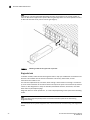
The serial port is located on the port side of the switch. The Brocade 5300 uses an RJ-45
connector for the serial port. An RJ-45 to DB9 adaptor cable is also provided with the switch.
NOTE
To protect the serial port from damage, keep the cover on the port when not in use.
The serial port can be used to connect to a workstation to configure the switch IP address before
connecting the switch to a fabric or IP network. The serial port’s parameters are fixed at 9600
baud, 8 data bits, and no parity, with flow control set to None.
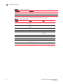
Table 12 lists the serial cable pinouts.
TABLE 12
Serial cable pinouts
PIN
Signal
Description
1
Not supported
NA
2
Not supported
NA
3
UART1_TXD
Transmit data
4
GND
Logic ground
5
GND
Logic ground
6
UART1_RXD
Receive data
7
Not supported
NA
8
Not supported
NA
Regulatory compliance
This section describes the regulatory compliance requirements for the Brocade 5300. It contains:
•
•
•
•
•
•
•
•
•
•
•
32
“FCC warning (US only),” next
“MIC statement (Republic of Korea)” on page 33
“VCCI statement Japan” on page 33
“Power cords (Japan Denan)” on page 33
“BSMI statement (Taiwan)” on page 33
“CE statement” on page 34
“Canadian requirements” on page 34
“Laser compliance” on page 34
“RTC battery” on page 34
“Electrical safety” on page 35
“Regulatory certifications” on page 35
Brocade 5300 Hardware Reference Manual
58-1000858-02