1
AMT ACCEL-5350
AMT ACCEL-5350
User's Guide
User's Guide
Document No. 397000 B
Document No. 397000 B
AMT ACCEL-5350
User's Guide
Document No. 397000 B
AMT ACCEL-5350
AMT ACCEL-5350
User's Guide
User's Guide
Unpacking
Unpacking
Set Up
Set Up
Loading Paper
Loading Paper
Control Panel
Control Panel
Cleaning & Maintenance
Cleaning & Maintenance
Solving Problems
Solving Problems
Bottom-Feed Tractors
Bottom-Feed Tractors
Bar Codes
Bar Codes
Interfaces
Interfaces
Code Sets
Code Sets
Specifications
Specifications
Document No. 397000
Revision B
AMT DATASOUTH CORP.
4765 Calle Quetzal
Camarillo, CA 93012-8546
TEL: (805) 388-5799
FAX: (805) 389-3657
Document No. 397000
Revision B
AMT DATASOUTH CORP.
4765 Calle Quetzal
Camarillo, CA 93012-8546
TEL: (805) 388-5799
FAX: (805) 389-3657
User's Guide
User's Guide
ii Preface
ii Preface
User's Guide
Preface
User's Guide
Preface
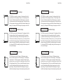
Thank you for selecting an AMT Datasouth® ACCEL™-5350 series
printer. Using an all-metal chassis, 24-wire dot-matrix printhead, stateof-the-art electronics, and simple user controls, your printer will provide
fast and reliable printing for years to come.
Printer Models
Thank you for selecting an AMT Datasouth® ACCEL™-5350 series
printer. Using an all-metal chassis, 24-wire dot-matrix printhead, stateof-the-art electronics, and simple user controls, your printer will provide
fast and reliable printing for years to come.
Printer Models
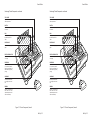
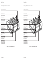
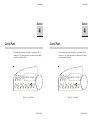
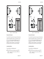
There are two models of AMT Datasouth ACCEL-5350 series printers.
They look different but operate the same. The 5350 has two paper paths
(top and rear) and the 5350d has three paper paths (top, rear and
bottom).
There are two models of AMT Datasouth ACCEL-5350 series printers.
They look different but operate the same. The 5350 has two paper paths
(top and rear) and the 5350d has three paper paths (top, rear and
bottom).
Preface iii
Preface iii
User's Guide
User's Guide
About This User's Guide
About This User's Guide
iv Preface
This user's guide provides information that will help you set up and
operate your printer. If you are using the printer for the first time, you
should perform the procedures in sections 1, 2 and 3 to set up the printer.
Then, use section 4 to learn how to use control panel functions. The rest
of the guide contains reference information that will help you get the
most from your printer.
The guide is divided into six sections and five appendixes:
The guide is divided into six sections and five appendixes:
Section 1, Unpacking, describes how to find a good place for your
printer and unpack it.
Section 1, Unpacking, describes how to find a good place for your
printer and unpack it.
Section 2, Set Up, points out the various components you use to
operate the printer and describes how to install the paper deflector,
ribbon cartridge and Intelli-card. It also describes how to check the
voltage select switch, attach the power cable, turn the printer on,
load paper, print a self test and attach the interface cables.
Section 3, Loading Paper, describes how to load various kinds of
media into the printer, including single sheets, pin-feed paper,
multipart forms, labels and transparencies.
Section 3, Loading Paper, describes how to load various kinds of
media into the printer, including single sheets, pin-feed paper,
multipart forms, labels and transparencies.
Section 4, Control Panel, describes how to use the control panel.
Section 4, Control Panel, describes how to use the control panel.
Section 5, Cleaning and Maintenance, describes how to keep your
printer in good shape and how to replace the ribbon cartridge, printhead and fuse.
Section 5, Cleaning and Maintenance, describes how to keep your
printer in good shape and how to replace the ribbon cartridge, printhead and fuse.
Section 6, Solving Problems, describes printer messages, provides a
troubleshooting guide, and shows how to run printer tests.
Section 6, Solving Problems, describes printer messages, provides a
troubleshooting guide, and shows how to run printer tests.
Appendix A, Bottom-Feed Tractors, describes how to use the
powered bottom-feed forms tractors.
Appendix A, Bottom-Feed Tractors, describes how to use the
powered bottom-feed forms tractors.
Appendix B, Bar Codes, provides information on printing bar codes.
Appendix B, Bar Codes, provides information on printing bar codes.
Appendix C, Interfaces, provides technical information on the
parallel and serial interfaces of the printer.
Appendix C, Interfaces, provides technical information on the
parallel and serial interfaces of the printer.
Appendix D, Code Sets, describes the printer's code sets.
Appendix D, Code Sets, describes the printer's code sets.
Appendix E, Specifications, lists printer specifications.
Appendix E, Specifications, lists printer specifications.
iv Preface
User's Guide
Conventions
User's Guide
Conventions
Some of the procedures in this guide contain special notices that
highlight important information:
Some of the procedures in this guide contain special notices that
highlight important information:
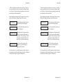
Notes
Indicate information that you should know to help
your printer run properly and efficiently.
Notes
Indicate information that you should know to help
your printer run properly and efficiently.
Cautions
Indicate guidelines that, if not followed, can cause
damage to equipment.
Cautions
Indicate guidelines that, if not followed, can cause
damage to equipment.
Warnings
Indicate a situation where there may be a danger to
yourself.
Warnings
Indicate a situation where there may be a danger to
yourself.
The use of the terms right and left assume that you are looking at the
front of the printer.
Technical Support
The use of the terms right and left assume that you are looking at the
front of the printer.
Technical Support
If you have a problem with your printer, refer to the Solving Problems
section for troubleshooting information. If you are unable to solve the
problem yourself, contact the Dealer that sold you the printer. The
Dealer should be able to assist you or tell you where to find additional
help.
Trademarks
AMT Datasouth is a registered trademark of Advanced Matrix
Technology, Inc. ACCEL, Intelli-card and Select-dial are trademarks of
Advanced Matrix Technology, Inc. All other brands and product names
are registered trademarks of their respective owners.
Preface v
AMT Datasouth is a registered trademark of Advanced Matrix
Technology, Inc. ACCEL, Intelli-card and Select-dial are trademarks of
Advanced Matrix Technology, Inc. All other brands and product names
are registered trademarks of their respective owners.
Preface v
User's Guide
User's Guide
Copyright
Copyright
© Copyright, 2000 by AMT Datasouth Corp. (AMT Datasouth). All
rights reserved. No part of this publication may be reproduced,
stored in a retrieval system, or transmitted, in any form or by any
means, mechanical, photocopying, recording or otherwise, without the
prior written permission of AMT Datasouth. No patent liability is
assumed with respect to the use of the information contained herein.
AMT Datasouth assumes no responsibility for errors or omissions.
Neither is any liability assumed for damages resulting from the use of
information contained herein. Changes are made periodically to the
information in this publication; these changes will be incorporated into
future editions. AMT Datasouth is without obligation to notify any
person of such revisions.
One-Year Limited Warranty
vi Preface
© Copyright, 2000 by AMT Datasouth Corp. (AMT Datasouth). All
rights reserved. No part of this publication may be reproduced,
stored in a retrieval system, or transmitted, in any form or by any
means, mechanical, photocopying, recording or otherwise, without the
prior written permission of AMT Datasouth. No patent liability is
assumed with respect to the use of the information contained herein.
AMT Datasouth assumes no responsibility for errors or omissions.
Neither is any liability assumed for damages resulting from the use of
information contained herein. Changes are made periodically to the
information in this publication; these changes will be incorporated into
future editions. AMT Datasouth is without obligation to notify any
person of such revisions.
One-Year Limited Warranty
AMT Datasouth Corp. ("AMT Datasouth") warrants your printer to be
free from defects in materials and workmanship for a period of one year
from the date of purchase from AMT Datasouth or an Authorized AMT
Datasouth Dealer. This warranty is limited to the original purchaser
("Purchaser") of the printer and is not transferable.
AMT Datasouth's obligation under this warranty is limited to replacing or
repairing, at its option, at its designated site, and by its designated agent,
any products or major assemblies that are returned to AMT Datasouth or
its agent within the warranty period that are found by AMT Datasouth to
be defective in proper usage. Purchaser may, at its option, return the
printer to AMT Datasouth or disassemble the printer and return to AMT
Datasouth only the major assembly needing repair, referencing in writing
the serial number of the major assembly needing repair and the serial
number of the product from which the assembly is removed. Purchaser
shall prepay transportation and insurance charges to AMT Datasouth's
designated site. If returned parts are repaired or replaced under the
terms of this warranty, AMT Datasouth will prepay transportation
charges back to Purchaser's location; otherwise, Purchaser shall pay
transportation and insurance charges in both directions.
vi Preface
User's Guide
User's Guide
Dated proof-of-purchase must be provided by the Purchaser when
requesting warranty work to be performed. (A warranty reply card is
included with the product and should be returned to AMT Datasouth
within 10 days of accepting the product.) The Purchaser may request
information on how to get warranty service by contacting an Authorized
AMT Datasouth Dealer or writing to AMT Datasouth, 4216 Stuart
Andrew Blvd. Charlotte, NC 28217 for further information.
THE FOREGOING LIMITED WARRANTY IS IN LIEU OF ALL
OTHER WARRANTIES WITH RESPECT TO THE PRODUCTS,
EITHER EXPRESSED OR IMPLIED, INCLUDING WITHOUT
LIMITATION ANY IMPLIED WARRANTY OF MERCHANTABILITY OR FITNESS FOR A PARTICULAR PURPOSE, AND
ANY OTHER OBLIGATION ON THE PART OF AMT.
THE FOREGOING LIMITED WARRANTY IS IN LIEU OF ALL
OTHER WARRANTIES WITH RESPECT TO THE PRODUCTS,
EITHER EXPRESSED OR IMPLIED, INCLUDING WITHOUT
LIMITATION ANY IMPLIED WARRANTY OF MERCHANTABILITY OR FITNESS FOR A PARTICULAR PURPOSE, AND
ANY OTHER OBLIGATION ON THE PART OF AMT.
THE FOREGOING LIMITED WARRANTY SHALL CONSTITUTE
THE SOLE AND EXCLUSIVE OBLIGATION AND LIABILITY OF
AMT. IN NO EVENT SHALL AMT BE LIABLE FOR INDIRECT,
INCIDENTAL OR CONSEQUENTIAL DAMAGES, AND IN NO
EVENT SHALL THE LIABILITY OF AMT ARISING IN CONNECTION WITH ANY PRINTER SOLD HEREUNDER (WHETHER
SUCH LIABILITY ARISES FROM A CLAIM BASED ON CONTRACT, WARRANTY, TORT OR OTHERWISE) EXCEED THE
ACTUAL AMOUNT PAID BY THE PURCHASER FOR THE
PRINTER.
Preface vii
Preface vii
User's Guide
User's Guide
Factory Service
Factory Service
viii Preface
If you suspect that your printer needs service, first contact the Dealer that
sold you the printer. The Dealer will ask you for the printer's model
number and serial number, the date you purchased the printer, and an
explanation of the problem. In the event that your Dealer is unable to
help you and the warranty period is in effect, contact AMT Datasouth,
4216 Stuart Andrew Blvd. Charlotte, NC 28217, phone 800-476-2450 and
press 4 for the Technical Support Department. Be ready to provide the
name of the Dealer that you contacted, the printer's model number and
serial number, the date you purchased the printer, and an explanation of
the problem.
If the AMT Datasouth Technical Support Representative is unable to
solve the problem on the phone, you will be issued a Return Materials
Authorization number (RMA number) and an address where to ship your
printer for service. You must write the RMA number on the outside of
the printer's shipping carton so that AMT Datasouth will accept the
printer when it arrives at the Service Center. You must also enclose a
copy of your purchase receipt or some other proof of the date of original
purchase. You must send your printer prepaid and with adequate insurance to the supplied address. If the printer is repaired under the terms of
the warranty, AMT Datasouth will prepay transportation charges back to
your location, provided that this location is within the continental United
States; otherwise, you must pay transportation and insurance charges in
both directions.
YOU MUST USE THE ORIGINAL PACKING MATERIAL TO SHIP
YOUR PRINTER; OTHERWISE, A CHARGE WILL BE INCURRED
FOR REPACKAGING.
YOU MUST USE THE ORIGINAL PACKING MATERIAL TO SHIP
YOUR PRINTER; OTHERWISE, A CHARGE WILL BE INCURRED
FOR REPACKAGING.
viii Preface
User's Guide
Agency Compliances
User's Guide
Agency Compliances
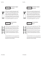
AMT Datasouth ACCEL-5350 and -5350d series printers have been
tested and found to comply with the application U.S. and Canadian
requirements of Underwriter's Laboratory Inc.®
AMT Datasouth ACCEL-5350 and -5350d series printers have been
tested and found to comply with the application U.S. and Canadian
requirements of Underwriter's Laboratory Inc.®
LISTED
EDP EQUIPMENT
94KO
LISTED
EDP EQUIPMENT
94KO
File Number E99947
File Number E99947
Information to the user for Class A digital device
Information to the user for Class A digital device
WARNING: This equipment has been tested and found to comply with
WARNING: This equipment has been tested and found to comply with
the limits for Class A digital device pursuant to Part 15 of the FCC
Rules. These limits are designed to provide reasonable protection
against harmful interference when the equipment is operated in a
commercial environment. This equipment generates, uses, and can
radiate radio frequence energy and, if not installed and used in
accordance with the instruction's manual, may cause inteference to radio
communications. Operation of this equipment in a residential area is
likely to cause interference in which case the user will be required to
correct the interference at his own expense.
The user is cautioned that changes and modifications made to the
equipment without approval of the manufacturer could void the user's
authority to operate this equipment.
The user is cautioned that changes and modifications made to the
equipment without approval of the manufacturer could void the user's
authority to operate this equipment.
It is suggested that the user use only shielded and grounded cables to
ensure compliance with FCC Rules.
It is suggested that the user use only shielded and grounded cables to
ensure compliance with FCC Rules.
AMT Datasouth ACCEL-5350 and -5350d series printers have been
tested and found to comply with the applicable requirements of the EPA
Energy Star guidelines for efficiency. The ENERGY STAR™ emblem does
not represent EPA endorsement of any product or service.
AMT Datasouth ACCEL-5350 and -5350d series printers have been
tested and found to comply with the applicable requirements of the EPA
Energy Star guidelines for efficiency. The ENERGY STAR™ emblem does
not represent EPA endorsement of any product or service.
Preface ix
Preface ix
User's Guide
User's Guide
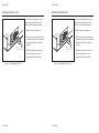
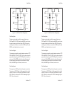
Power Precautions
Power Precautions
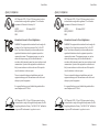
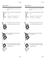
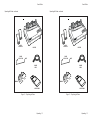
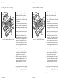
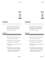
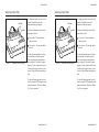
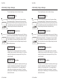
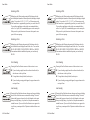
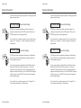
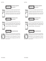
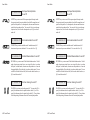
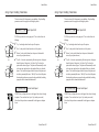
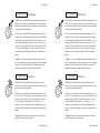
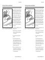
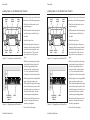
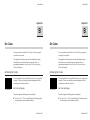
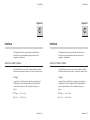
When installing and using the printer, be sure to take the following
precautions:
L
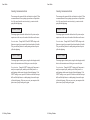
Use the appropriate power supply and voltage frequency. Be sure to
check the voltage select switch before the printer's first installation.
GND
When installing and using the printer, be sure to take the following
precautions:
L
Use the appropriate power supply and voltage frequency. Be sure to
check the voltage select switch before the printer's first installation.
GND
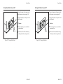
N
N
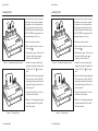
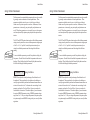
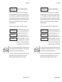
Make sure the total length of the power cord does not exceed 16.4
feet (5 meters). Using a longer power cord can result in reduced
voltage and possible malfunctions. Do not use an extension cord.
After turning the power off, always wait at least five seconds before
turning it back on.
OFF
0:05
Make sure the total length of the power cord does not exceed 16.4
feet (5 meters). Using a longer power cord can result in reduced
voltage and possible malfunctions. Do not use an extension cord.
After turning the power off, always wait at least five seconds before
turning it back on.
OFF
0:05
ON
x Preface
ON
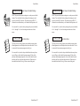
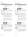
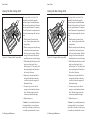
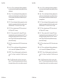
In case of smoke, odd smells, or other trouble, unplug the power
cord. Do not place furniture or other obstacles in front of the outlet.
In case of smoke, odd smells, or other trouble, unplug the power
cord. Do not place furniture or other obstacles in front of the outlet.
Caution: When unplugging the power cord, pull the plug, not
the cord.
Caution: When unplugging the power cord, pull the plug, not
the cord.
x Preface
User's Guide
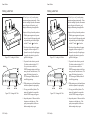
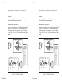
Operating Precautions
User's Guide
Operating Precautions
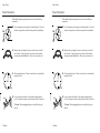
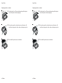
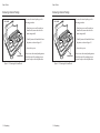
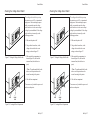
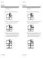
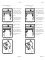
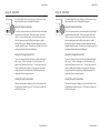
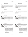
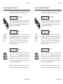
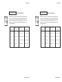
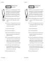
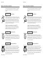
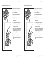
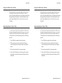
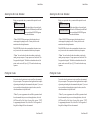
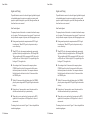
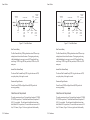
When installing and using the printer, be sure to take the following
precautions:
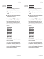
115° F
46° C
45° F
7° C
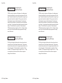
Use the printer only within the following temperature and humidity
ranges:
Ambient temperature: 7° to 46° Centigrade (45° to 115° F)
Relative humidity:
10% to 85% noncondensing
When installing and using the printer, be sure to take the following
precautions:
115° F
46° C
45° F
7° C
Use the printer only within the following temperature and humidity
ranges:
Ambient temperature: 7° to 46° Centigrade (45° to 115° F)
Relative humidity:
10% to 85% noncondensing
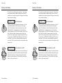
Avoid direct sunlight. Use a blind or heavy curtain to protect the
printer from direct sunlight when the printer is near a window.
Avoid direct sunlight. Use a blind or heavy curtain to protect the
printer from direct sunlight when the printer is near a window.
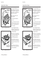
Do not install the printer near devices that contain magnets or
generate magnetic fields.
Do not install the printer near devices that contain magnets or
generate magnetic fields.
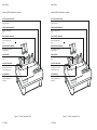
Place the printer on a flat, horizontal surface. Protect the printer
from strong physical shocks and vibrations. Lift the printer from
underneath and on both sides.
Place the printer on a flat, horizontal surface. Protect the printer
from strong physical shocks and vibrations. Lift the printer from
underneath and on both sides.
Preface xi
Preface xi
User's Guide
User's Guide
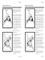
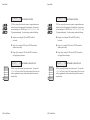
Operating precautions––continued
Operating precautions––continued
xii Preface
Keep the printer clean. Dust accumulation and paper fiber deposits
can cause the printer to function improperly.
Keep the printer clean. Dust accumulation and paper fiber deposits
can cause the printer to function improperly.
Do not place cups, books or other objects on top of the printer. Be
careful not to hang jewelry, clothes or hair near the paper entry slots.
Do not place cups, books or other objects on top of the printer. Be
careful not to hang jewelry, clothes or hair near the paper entry slots.
Do not install the printer near an air conditioner.
Do not install the printer near an air conditioner.
xii Preface
User's Guide
Contents
User's Guide
Contents
Preface
Printer Models .............................................................................
About This User's Guide .............................................................
Conventions ..................................................................................
Technical Support ........................................................................
Trademarks ..................................................................................
Copyright ......................................................................................
One-Year Limited Warranty .......................................................
Factory Service ............................................................................
Agency Compliances ...................................................................
Power Precautions .......................................................................
Operating Precautions .................................................................
iii
iii
iv
v
v
v
vi
vi
viii
ix
x
xi
Contents
xiii
Contents
xiii
Figures and Tables
xxi
Figures and Tables
xxi
Section 1—Unpacking
1-1
Section 1—Unpacking
1-1
Selecting a Good Place for the Printer ........................................
Unpacking the Printer ..................................................................
Removing Internal Packing .........................................................
1-1
1-2
1-4
Contents xiii
Selecting a Good Place for the Printer ........................................
Unpacking the Printer ..................................................................
Removing Internal Packing .........................................................
1-1
1-2
1-4
Contents xiii
User's Guide
User's Guide
Section 2—Set Up
Introducing Printer Components .................................................
Installing the Paper Deflector ......................................................
Installing the Ribbon Cartridge ...................................................
Checking the Voltage Select Switch ............................................
Attaching the Power Cord ...........................................................
Turning the Printer On and Off ...................................................
Printing a Self Test ......................................................................
Attaching the Interface Cable .....................................................
Setting Communications Parameters ...........................................
Configuring Software ...................................................................
Selecting the Correct Printer ..................................................
Selecting the Correct Output Port ...........................................
Section 3—Loading Paper
Choosing Paper ............................................................................
Paper Paths ..................................................................................
Selecting a Paper Path .................................................................
Loading Forms .............................................................................
Positioning a Form ..................................................................
Ejecting a Form.......................................................................
Loading Pin-Feed Report Paper ..................................................
Positioning Pin-Feed Report Paper .........................................
Advancing Pin-Feed Report Paper .........................................
Using the Demand Document Mode ......................................
Using Paper Park ....................................................................
Unloading Pin-Feed Report Paper ..........................................
Loading Multipart Forms ..............................................................
Loading Labels .............................................................................
Loading Transparencies ...............................................................
Aligning Preprinted Forms ...........................................................
Setting Page Length .....................................................................
Reviewing the Paper Handling Controls ......................................
Section 4—Control Panel
Understanding Display Messages ...........................................
Status ......................................................................................
Alternate Status .......................................................................
xiv Contents
2-1
Section 2—Set Up
2-1
2-5
2-6
2-7
2-8
2-9
2-10
2-11
2-12
2-13
2-13
2-13
Introducing Printer Components .................................................
Installing the Paper Deflector ......................................................
Installing the Ribbon Cartridge ...................................................
Checking the Voltage Select Switch ............................................
Attaching the Power Cord ...........................................................
Turning the Printer On and Off ...................................................
Printing a Self Test ......................................................................
Attaching the Interface Cable .....................................................
Setting Communications Parameters ...........................................
Configuring Software ...................................................................
Selecting the Correct Printer ..................................................
Selecting the Correct Output Port ...........................................
3-1
Section 3—Loading Paper
3-1
3-2
3-3
3-4
3-5
3-5
3-6
3-8
3-8
3-8
3-11
3-11
3-12
3-12
3-13
3-14
3-14
3-16
Choosing Paper ............................................................................
Paper Paths ..................................................................................
Selecting a Paper Path .................................................................
Loading Forms .............................................................................
Positioning a Form ..................................................................
Ejecting a Form.......................................................................
Loading Pin-Feed Report Paper ..................................................
Positioning Pin-Feed Report Paper .........................................
Advancing Pin-Feed Report Paper .........................................
Using the Demand Document Mode ......................................
Using Paper Park ....................................................................
Unloading Pin-Feed Report Paper ..........................................
Loading Multipart Forms ..............................................................
Loading Labels .............................................................................
Loading Transparencies ...............................................................
Aligning Preprinted Forms ...........................................................
Setting Page Length .....................................................................
Reviewing the Paper Handling Controls ......................................
4-1
Section 4—Control Panel
4-2
4-2
4-2
Understanding Display Messages ...........................................
Status ......................................................................................
Alternate Status .......................................................................
xiv Contents
2-1
2-1
2-5
2-6
2-7
2-8
2-9
2-10
2-11
2-12
2-13
2-13
2-13
3-1
3-1
3-2
3-3
3-4
3-5
3-5
3-6
3-8
3-8
3-8
3-11
3-11
3-12
3-12
3-13
3-14
3-14
3-16
4-1
4-2
4-2
4-2
User's Guide
Operator and Error ..................................................................
Setup Menu .............................................................................
Using the Select-Dial ...................................................................
Moving the Paper Up and Down ............................................
Moving the Carriage Back and Forth .....................................
Scrolling Through the Setup Menu ........................................
Using the Control Panel Buttons .................................................
Turning Printing On and Off ..................................................
Selecting a Printer Emulation .................................................
Selecting a Text Quality .........................................................
Selecting a Font ......................................................................
Selecting a Pitch .....................................................................
Selecting a Color ....................................................................
Form Feeding ..........................................................................
Line Feeding ...........................................................................
Setting the Top-Of-Form ........................................................
Moving the Bail ......................................................................
Parking the Paper ....................................................................
Clearing the Buffer .................................................................
Resetting the Printer ...............................................................
Printing a Self Test .................................................................
Printing a Printer Status Report ..............................................
Displaying the Setup Menu ....................................................
Using the Setup Menu .................................................................
Selecting Operations ....................................................................
Restore Printer Settings ..........................................................
Save Printer Settings ...............................................................
Select Power-On Default Settings ..........................................
Run Printer Tests ....................................................................
Selecting Print Modes ..................................................................
Set Printer Emulation ..............................................................
Turn Quiet Mode On and Off .................................................
Set Language ..........................................................................
Select Characters for Codes 128-255 .....................................
Turn Automatic Carriage Return Mode On and Off ..............
Turn Automatic Line Feed Mode On and Off ........................
Select Audible Alarm Mode ....................................................
4-2
4-2
4-3
4-3
4-3
4-3
4-4
4-4
4-5
4-5
4-5
4-6
4-6
4-6
4-6
4-7
4-7
4-7
4-7
4-8
4-8
4-9
4-9
4-11
4-16
4-16
4-16
4-17
4-17
4-18
4-18
4-18
4-19
4-20
4-22
4-22
4-22
Contents xv
User's Guide
User's Guide
Using Text Appearance Parameters
Set Print Quality ......................................................................
Set Font ...................................................................................
Set Pitch ..................................................................................
Set Character Cell Size ...........................................................
Set Number of Lines per Inch ................................................
Set Color .................................................................................
Turn Italic Mode On and Off ..................................................
Turn Double-High Mode On and Off .....................................
Turn Double-Wide Mode On and Off ....................................
Turn Super/Subscript Modes On and Off ...............................
Turn Underline Mode On and Off ..........................................
Turn Bold/Shadow Modes On and Off ...................................
Turn Zero Slashing On and Off ..............................................
Set Printing Direction .............................................................
Using Page Setup Paramaters .....................................................
Set Form Length .....................................................................
Set Maximum Print Width .......................................................
Set Top Margin .......................................................................
Set Bottom Margin ..................................................................
Set Left Margin .......................................................................
Set Right Margin .....................................................................
Turn Automatic Form Feed Mode On and Off ......................
Using Paper Handling Parameters ..............................................
Select Paper Path ...................................................................
Set Line Feed Speed ...............................................................
Turn Demand Document Mode On and Off ..........................
Turn Paper Jam Sensing On and Off .....................................
Select Page End Method ........................................................
Turn Preprinted Forms Alignment Mode On and Off ............
Turn Automatic Bail Mode On and Off ..................................
Set Print Density .....................................................................
Set Print Force ........................................................................
Specifying Communications Parameters .....................................
Select Interface .......................................................................
Specify Baud Rate ..................................................................
Specify Input Buffer Size ........................................................
Specify Handshaking Method .................................................
xvi Contents
Using Text Appearance Parameters
Set Print Quality ......................................................................
Set Font ...................................................................................
Set Pitch ..................................................................................
Set Character Cell Size ...........................................................
Set Number of Lines per Inch ................................................
Set Color .................................................................................
Turn Italic Mode On and Off ..................................................
Turn Double-High Mode On and Off .....................................
Turn Double-Wide Mode On and Off ....................................
Turn Super/Subscript Modes On and Off ...............................
Turn Underline Mode On and Off ..........................................
Turn Bold/Shadow Modes On and Off ...................................
Turn Zero Slashing On and Off ..............................................
Set Printing Direction .............................................................
Using Page Setup Paramaters .....................................................
Set Form Length .....................................................................
Set Maximum Print Width .......................................................
Set Top Margin .......................................................................
Set Bottom Margin ..................................................................
Set Left Margin .......................................................................
Set Right Margin .....................................................................
Turn Automatic Form Feed Mode On and Off ......................
Using Paper Handling Parameters ..............................................
Select Paper Path ...................................................................
Set Line Feed Speed ...............................................................
Turn Demand Document Mode On and Off ..........................
Turn Paper Jam Sensing On and Off .....................................
Select Page End Method ........................................................
Turn Preprinted Forms Alignment Mode On and Off ............
Turn Automatic Bail Mode On and Off ..................................
Set Print Density .....................................................................
Set Print Force ........................................................................
Specifying Communications Parameters .....................................
Select Interface .......................................................................
Specify Baud Rate ..................................................................
Specify Input Buffer Size ........................................................
Specify Handshaking Method .................................................
4-23
4-23
4-23
4-24
4-24
4-25
4-25
4-25
4-25
4-26
4-26
4-26
4-26
4-27
4-28
4-28
4-28
4-29
4-29
4-29
4-30
4-30
4-31
4-31
4-31
4-32
4-33
4-33
4-34
4-34
4-35
4-35
4-36
4-36
4-36
4-36
4-37
xvi Contents
4-23
4-23
4-23
4-24
4-24
4-25
4-25
4-25
4-25
4-26
4-26
4-26
4-26
4-27
4-28
4-28
4-28
4-29
4-29
4-29
4-30
4-30
4-31
4-31
4-31
4-32
4-33
4-33
4-34
4-34
4-35
4-35
4-36
4-36
4-36
4-36
4-37
User's Guide
Specify Number of Data Bits .................................................
Specify Number of Stop Bits ..................................................
Specify Parity ..........................................................................
Set DTR Signal Polarity ..........................................................
Specify STROBE Pulse Edge for Data Capture ....................
Reviewing the Setup Menu ..........................................................
Section 5—Cleaning and Maintenance
4-37
4-37
4-38
4-38
4-38
4-39
5-1
Removing and Installing the Top Cover ...................................... 5-2
Cleaning the Platen and Bail Rollers ........................................... 5-3
Cleaning the Main Carriage Shaft ............................................... 5-4
Cleaning the Printhead Wires ...................................................... 5-5
Cleaning Printer Surfaces ............................................................ 5-6
Replacing the Ribbon Cartridge .................................................. 5-7
Replacing the Fuse....................................................................... 5-7
Inspecting Printer Parts ................................................................ 5-8
Replacing the Printhead ............................................................... 5-10
Section 6—Solving Problems
6-1
Understanding Printer Messages .................................................
Correcting Operating Errors ...................................................
Correcting Programming Errors .............................................
Understanding Messages ........................................................
Understanding Warnings .........................................................
Correcting Communication Errors ..........................................
Correcting Printer Errors ........................................................
Troubleshooting Problems ............................................................
Running Printer Tests ..................................................................
Checking Memory ...................................................................
Checking Sensors and Switches .............................................
Checking Ribbon Alignment ....................................................
Checking Printing Alignment ..................................................
Re-Calibrating the Paper Sensor .................................................
Checking Carriage Movement .....................................................
Checking the Platen .....................................................................
Aligning the Ribbon ......................................................................
Fine-Adjusting the Top-Of-Form .................................................
Fine-Adjusting the Forms Tear-Off Position ...............................
6-1
6-2
6-4
6-5
6-7
6-8
6-10
6-12
6-21
6-21
6-22
6-24
6-25
6-26
6-27
6-28
6-29
6-30
6-30
Contents xvii
User's Guide
User's Guide
Fine-Adjusting the Carriage Home Position ................................
Fine-Adjusting the Paper Sensor .................................................
Changing User Names .................................................................
Locking Control Panel Functions .................................................
Disabling the Cover Open Interlock ............................................
Appendix A—Bottom-Feed Tractors
Selecting a Printer Stand ..............................................................
Activating the Bottom-Feed Tractors ..........................................
Accessing the Bottom-Feed Tractors ..........................................
Loading Paper in the Bottom-Feed Tractors ...............................
Using the Bottom-Feed Tractors .................................................
Alternating Between Paper Paths ...............................................
Troubleshooting ............................................................................
Appendix B—Bar Codes
Introducing Bar Codes .................................................................
Selecting the Bar Code Emulation ...............................................
Printing Bar Codes .......................................................................
Bar Code Specifications ..............................................................
Appendix C—Interfaces
Centronics Parallel Interface .......................................................
Voltages ..................................................................................
Signals and Timing ..................................................................
Cable/Connector Requirements ..............................................
Setting Parallel Parameters .....................................................
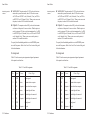
Pin Assignments ......................................................................
RS-232-C Serial Interface ...........................................................
Voltages ..................................................................................
Signals and Data Format .........................................................
Cable/Connector Requirements ..............................................
Setting Serial Parameters ........................................................
Handshaking Methods .............................................................
Pin Assignments ......................................................................
xviii Contents
6-31
6-31
6-32
6-33
6-34
Fine-Adjusting the Carriage Home Position ................................
Fine-Adjusting the Paper Sensor .................................................
Changing User Names .................................................................
Locking Control Panel Functions .................................................
Disabling the Cover Open Interlock ............................................
A-1
Appendix A—Bottom-Feed Tractors
A-2
A-2
A-3
A-4
A-5
A-5
A-6
Selecting a Printer Stand ..............................................................
Activating the Bottom-Feed Tractors ..........................................
Accessing the Bottom-Feed Tractors ..........................................
Loading Paper in the Bottom-Feed Tractors ...............................
Using the Bottom-Feed Tractors .................................................
Alternating Between Paper Paths ...............................................
Troubleshooting ............................................................................
B-1
Appendix B—Bar Codes
B-1
B-3
B-3
B-4
Introducing Bar Codes .................................................................
Selecting the Bar Code Emulation ...............................................
Printing Bar Codes .......................................................................
Bar Code Specifications ..............................................................
C-1
Appendix C—Interfaces
C-1
C-1
C-2
C-4
C-5
C-5
C-8
C-8
C-8
C-10
C-11
C-11
C-12
Centronics Parallel Interface .......................................................
Voltages ..................................................................................
Signals and Timing ..................................................................
Cable/Connector Requirements ..............................................
Setting Parallel Parameters .....................................................
Pin Assignments ......................................................................
RS-232-C Serial Interface ...........................................................
Voltages ..................................................................................
Signals and Data Format .........................................................
Cable/Connector Requirements ..............................................
Setting Serial Parameters ........................................................
Handshaking Methods .............................................................
Pin Assignments ......................................................................
xviii Contents
6-31
6-31
6-32
6-33
6-34
A-1
A-2
A-2
A-3
A-4
A-5
A-5
A-6
B-1
B-1
B-3
B-3
B-4
C-1
C-1
C-1
C-2
C-4
C-5
C-5
C-8
C-8
C-8
C-10
C-11
C-11
C-12
User's Guide
Appendix D—Code Sets
D-1
AMT and Diablo 630 Code Set ...................................................
Character Codes ......................................................................
Printing Characters Assigned to Control Codes ................
Printing International Characters .......................................
Control Codes and Escape Sequences ....................................
Epson JX, Epson LQ-2550 and IBM XL24 Code Set .................
Character Codes ......................................................................
Printing Characters Assigned to Control Codes ................
Printing International Characters .......................................
ECS Fonts ..........................................................................
Control Codes and Escape Sequences ....................................
Bar Code Escape Sequences ........................................................
ASCII Code Table .......................................................................
Appendix E—Specifications
D-2
D-2
D-2
D-4
D-4
D-21
D-21
D-21
D-23
D-23
D-23
D-49
D-50
E-1
User's Guide
Appendix D—Code Sets
AMT and Diablo 630 Code Set ...................................................
Character Codes ......................................................................
Printing Characters Assigned to Control Codes ................
Printing International Characters .......................................
Control Codes and Escape Sequences ....................................
Epson JX, Epson LQ-2550 and IBM XL24 Code Set .................
Character Codes ......................................................................
Printing Characters Assigned to Control Codes ................
Printing International Characters .......................................
ECS Fonts ..........................................................................
Control Codes and Escape Sequences ....................................
Bar Code Escape Sequences ........................................................
ASCII Code Table .......................................................................
Appendix E—Specifications
Warranty Registration
Warranty Registration
Request for Reader's Comments
Request for Reader's Comments
Contents xix
D-1
D-2
D-2
D-2
D-4
D-4
D-21
D-21
D-21
D-23
D-23
D-23
D-49
D-50
E-1
Contents xix
User's Guide
User's Guide
xx Contents
xx Contents
User's Guide
Figures and Tables
User's Guide
Figures and Tables
Figures
Figures
1-1
1-2
Unpacking the Printer .............................................................
Removing the Foam Blocks ....................................................
1-3
1-4
1-1
1-2
Unpacking the Printer .............................................................
Removing the Foam Blocks ....................................................
1-3
1-4
2-1
2-2
2-3
2-4
2-5
2-6
2-7
2-8
2-9
2-10
2-11
2-12
2-13
2-14
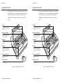
Printer Components, Front .....................................................
Printer Components, Internal ..................................................
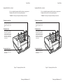
Printer Components, Rear .......................................................
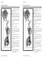
Installing the Paper Deflector .................................................
Hooking the Paper Deflector ..................................................
Installing a Ribbon Cartridge ...................................................
Setting the Voltage Select Switch ...........................................
Locating the Fuse Compartment .............................................
Attaching the Power Cord ......................................................
Turning On the Printer ............................................................
Loading a Cut Sheet ................................................................
Printing a Self Test .................................................................
Connecting the Parallel Cable .................................................
Connecting the Serial Cable ....................................................
2-2
2-3
2-4
2-5
2-5
2-6
2-7
2-7
2-8
2-9
2-10
2-10
2-11
2-11
2-1
2-2
2-3
2-4
2-5
2-6
2-7
2-8
2-9
2-10
2-11
2-12
2-13
2-14
Printer Components, Front .....................................................
Printer Components, Internal ..................................................
Printer Components, Rear .......................................................
Installing the Paper Deflector .................................................
Hooking the Paper Deflector ..................................................
Installing a Ribbon Cartridge ...................................................
Setting the Voltage Select Switch ...........................................
Locating the Fuse Compartment .............................................
Attaching the Power Cord ......................................................
Turning On the Printer ............................................................
Loading a Cut Sheet ................................................................
Printing a Self Test .................................................................
Connecting the Parallel Cable .................................................
Connecting the Serial Cable ....................................................
2-2
2-3
2-4
2-5
2-5
2-6
2-7
2-7
2-8
2-9
2-10
2-10
2-11
2-11
Contents xxi
Contents xxi
User's Guide
xxii Contents
User's Guide
3-1
3-2
3-3
3-4
3-5
3-6
3-7
3-8
3-9
Selecting a Paper Path ............................................................
Attaching the Support Extender .............................................
Loading a Form .......................................................................
Raising the Tractor Cover .......................................................
Unlocking the Tractors ...........................................................
Aligning the Left-Edge Tractor ..............................................
Loading Paper Into the Tractors .............................................
Making Sure the Paper is Taut ...............................................
Checking the Exit Path ...........................................................
3-3
3-4
3-4
3-6
3-6
3-6
3-7
3-7
3-7
3-1
3-2
3-3
3-4
3-5
3-6
3-7
3-8
3-9
Selecting a Paper Path ............................................................
Attaching the Support Extender .............................................
Loading a Form .......................................................................
Raising the Tractor Cover .......................................................
Unlocking the Tractors ...........................................................
Aligning the Left-Edge Tractor ..............................................
Loading Paper Into the Tractors .............................................
Making Sure the Paper is Taut ...............................................
Checking the Exit Path ...........................................................
4-1
4-2
4-3
Control Panel .......................................................................... 4-1
Sample Printer Status Report ................................................. 4-10
Setup Menu ............................................................................. 4-12
4-1
4-2
4-3
Control Panel .......................................................................... 4-1
Sample Printer Status Report ................................................. 4-10
Setup Menu ............................................................................. 4-12
5-1
5-2
5-3
5-4
5-5
5-6
5-7
5-8
5-9
5-10
Removing the Top Cover ........................................................ 5-2
Aligning the Platen Window and Top Cover ......................... 5-2
Cleaning the Platen and Bail Rollers ...................................... 5-3
Cleaning the Main Carriage Shaft .......................................... 5-4
Cleaning the Printhead Wires ................................................. 5-5
Cleaning the Printer Surfaces ................................................. 5-6
Cleaning the Forms Tractors .................................................. 5-6
Inspecting the Printer, Front ................................................... 5-8
Inspecting the Printer, Rear .................................................... 5-9
Replacing the Printhead .......................................................... 5-10
A-1
A-2
A-3
A-4
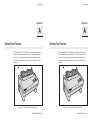
Printer With Bottom-Feed Tractors ........................................
Raising and Lowering the Printer ...........................................
Loading Paper in the Bottom Path ..........................................
Aligning Paper in the Bottom Path .........................................
A-1
A-3
A-4
A-4
A-1
A-2
A-3
A-4
Printer With Bottom-Feed Tractors ........................................
Raising and Lowering the Printer ...........................................
Loading Paper in the Bottom Path ..........................................
Aligning Paper in the Bottom Path .........................................
C-1
C-2
C-3
C-4
Parallel Data Transfer Timing Diagram ................................. C-3
Parallel Cable Assembly ......................................................... C-4
Serial Data Format .................................................................. C-10
Serial Cable Assembly ............................................................ C-11
xxii Contents
3-3
3-4
3-4
3-6
3-6
3-6
3-7
3-7
3-7
A-1
A-3
A-4
A-4
User's Guide
User's Guide
Tables
Tables
4-1
Setup Menu Summary ............................................................. 4-39
4-1
Setup Menu Summary ............................................................. 4-39
6-1
Troubleshooting Guide ........................................................... 6-12
6-1
Troubleshooting Guide ........................................................... 6-12
A-1 Troubleshooting the Bottom-Feed Tractors ...........................
A-6
A-1 Troubleshooting the Bottom-Feed Tractors ...........................
A-6
B-1 Bar Code Specifications .........................................................
B-4
B-1 Bar Code Specifications .........................................................
B-4
C-1 Parallel Pin Assignments ........................................................ C-5
C-2 Serial Pin Assignments ........................................................... C-12
C-1 Parallel Pin Assignments ........................................................ C-5
C-2 Serial Pin Assignments ........................................................... C-12
D-1
D-2
D-3
D-4
D-5
D-6
D-7
D-8
AMT and Diablo 630 Character Code Assignments ..............
AMT and Diablo 630 Control Codes .....................................
AMT and Diablo 630 Escape Sequences ...............................
Epson and IBM Character Code Assignments .......................
Epson and IBM Control Codes ...............................................
Epson and IBM Escape Sequences .........................................
Bar Code Escape Sequences ...................................................
ASCII Table ............................................................................
D-3
D-5
D-7
D-22
D-24
D-26
D-49
D-50
E-1
Specifications ..........................................................................
E-1
E-1
Specifications ..........................................................................
E-1
Contents xxiii
Contents xxiii
User's Guide
User's Guide
Section
Section
1
1
Unpacking
Unpacking
This section describes how to select a good place for the printer and
unpack it. If the printer is already set up, you can skip ahead to the
next section.
Selecting a Good Place for the Printer
This section describes how to select a good place for the printer and
unpack it. If the printer is already set up, you can skip ahead to the
next section.
Selecting a Good Place for the Printer
When selecting a place for your printer, observe the following guidelines:
When selecting a place for your printer, observe the following guidelines:
9 The site must be large enough to accommodate the printer: 24
inches (61 cm) wide by 19 inches (49 cm) deep.
9 The site must be large enough to accommodate the printer: 24
inches (61 cm) wide by 19 inches (49 cm) deep.
9 The printer must be close enough to the computer for your cable to
reach: 10 feet (3 meters) for parallel or 50 feet (15 meters) for serial.
9 The printer must be close enough to the computer for your cable to
reach: 10 feet (3 meters) for parallel or 50 feet (15 meters) for serial.
9 The printer must be on a flat, solid surface––never on a chair or any
other unstable support.
9 The printer must be on a flat, solid surface––never on a chair or any
other unstable support.
9 Choose a place that is clean and free from excessive heat (including
direct sunlight), moisture, and dust.
9 Choose a place that is clean and free from excessive heat (including
direct sunlight), moisture, and dust.
9 Use a grounded outlet––one that has three holes to match the power
plug on the printer. Don't use an adapter plug or an extension cord.
9 Use a grounded outlet––one that has three holes to match the power
plug on the printer. Don't use an adapter plug or an extension cord.
Unpacking 1-1
Unpacking 1-1
User's Guide
User's Guide
Selecting a Good Place for the Printer––continued
Selecting a Good Place for the Printer––continued
9
Avoid outlets on the same circuit with large motors, such as copiers
or postage machines, or other appliances that might disturb the
power supply.
9
Avoid outlets on the same circuit with large motors, such as copiers
or postage machines, or other appliances that might disturb the
power supply.
9
Leave several inches of empty space in front, behind, and on both
sides of the printer for good air flow.
9
Leave several inches of empty space in front, behind, and on both
sides of the printer for good air flow.
9
Leave proper clearances for your paper loading needs.
9
Leave proper clearances for your paper loading needs.
Unpacking the Printer
Unpacking the Printer
To unpack the printer, use the following procedure:
1-2 Unpacking
To unpack the printer, use the following procedure:
1. Cut the packing tape and open the shipping carton.
1. Cut the packing tape and open the shipping carton.
2. Remove the printer components from the top foam cap.
2. Remove the printer components from the top foam cap.
3. Lift out the top foam cap.
3. Lift out the top foam cap.
4. Remove the other items in the shipping carton.
4. Remove the other items in the shipping carton.
5. Carefully lift the printer out of the carton and place it on the site
you selected.
5. Carefully lift the printer out of the carton and place it on the site
you selected.
6. Remove the protective plastic covering from the printer.
6. Remove the protective plastic covering from the printer.
7. Peel off the tape that secures the wire locking loops on the parallel
interface connector. The parallel interface connector is located on
the back of the printer.
7. Peel off the tape that secures the wire locking loops on the parallel
interface connector. The parallel interface connector is located on
the back of the printer.
8. Verify that you have all of the items shown in figure 1-1. If anything is missing or damaged, contact the Dealer that sold you the
printer.
8. Verify that you have all of the items shown in figure 1-1. If anything is missing or damaged, contact the Dealer that sold you the
printer.
9. Fill in the Warranty Registration Card at the back of this guide and
mail it to AMT. Returning this card ensures that you will be
notified of the latest printer news and enhancements.
9. Fill in the Warranty Registration Card at the back of this guide and
mail it to AMT. Returning this card ensures that you will be
notified of the latest printer news and enhancements.
10. Be sure to save all of the packing materials in case you need to ship
or store the printer later.
10. Be sure to save all of the packing materials in case you need to ship
or store the printer later.
1-2 Unpacking
User's Guide
Unpacking the Printer––continued
User's Guide
Unpacking the Printer––continued
PAPER
SUPPORTS
PAPER
SUPPORTS
PRINTER
PAPER
DEFLECTOR
PRINTER
PAPER
DEFLECTOR
POWER
CORD
RIBBONS
POWER
CORD
RIBBONS
USER'S GUIDE
Figure 1-1. Unpacking the Printer
USER'S GUIDE
Figure 1-1. Unpacking the Printer
Unpacking 1-3
Unpacking 1-3
User's Guide
User's Guide
Removing Internal Packing
Removing Internal Packing
To remove the internal packing, use the
following procedure:
TOP COVER
FOAM BLOCKS
Figure 1-2. Removing the Foam Blocks
1-4 Unpacking
To remove the internal packing, use the
following procedure:
TOP COVER
1. Raise the top cover and locate the two
foam blocks (one on each side of the
main carriage shaft).
1. Raise the top cover and locate the two
foam blocks (one on each side of the
main carriage shaft).
2. Carefully remove the foam blocks from
the printer, as shown in figure 1-2.
2. Carefully remove the foam blocks from
the printer, as shown in figure 1-2.
3. Lower the top cover.
3. Lower the top cover.
Be sure to save the internal packing materials with the rest of the packaging in case
you need to ship or store the printer later.
FOAM BLOCKS
Figure 1-2. Removing the Foam Blocks
1-4 Unpacking
Be sure to save the internal packing materials with the rest of the packaging in case
you need to ship or store the printer later.
User's Guide
User's Guide
Section
Section
2
2
Set Up
Set Up
This section points out the various printer components that you use to
operate the printer and describes how to install the paper deflector and
ribbon cartridge. This section also describes how to check the voltage
select switch, attach the power cord, turn the printer on and off, load
paper, print a self test, and attach the interface cables.
Introducing Printer Components
You should familiarize yourself with the printer components that are
shown in the figures on the following pages. They are referred to in the
procedures throughout this guide.
Set Up 2-1
You should familiarize yourself with the printer components that are
shown in the figures on the following pages. They are referred to in the
procedures throughout this guide.
Set Up 2-1
User's Guide
User's Guide
Introducing Printer Components––continued
Introducing Printer Components––continued
SELECT-DIAL CONTROL PANEL
SELECT-DIAL CONTROL PANEL
Provides easy setup and configuration of the printer
Provides easy setup and configuration of the printer
FORMS THICKNESS INDICATOR
FORMS THICKNESS INDICATOR
Shows the current forms thickness
Shows the current forms thickness
TRACTOR SELECT INDICATOR
TRACTOR SELECT INDICATOR
Shows whether the rear forms
tractors are engaged or disengaged
Shows whether the rear forms
tractors are engaged or disengaged
PAPER SUPPORT EXTENDERS
PAPER SUPPORT EXTENDERS
Provide additional support for
long, single sheets
Provide additional support for
long, single sheets
PAPER SUPPORT
PAPER SUPPORT
Guides single sheets into the
printer
Guides single sheets into the
printer
PLATEN ACCESS COVER
PLATEN ACCESS COVER
Permits access to the platen
shaft and gears for mounting
paper handling accessories
Permits access to the platen
shaft and gears for mounting
paper handling accessories
PLATEN WINDOW
PLATEN WINDOW
Lets you see printing in progress
and helps guide paper as it exits the printer
Lets you see printing in progress
and helps guide paper as it exits the printer
Figure 2-1. Printer Components, Front
2-2 Set Up
Figure 2-1. Printer Components, Front
2-2 Set Up
User's Guide
User's Guide
Introducing Printer Components––continued
Introducing Printer Components––continued
TOP COVER
TOP COVER
Opens to reveal the carriage,
ribbon and printhead
Opens to reveal the carriage,
ribbon and printhead
PLATEN
PLATEN
Provides a firm print impression surface
Provides a firm print impression surface
BAIL
BAIL
Holds paper firmly against
the platen with pressure
rollers
Holds paper firmly against
the platen with pressure
rollers
PAPER SCALE
PAPER SCALE
Provides an easy way to align
paper
Provides an easy way to align
paper
PRINT LINE INDICATOR
PRINT LINE INDICATOR
Shows the current print line
on the page
Shows the current print line
on the page
PRINTHEAD
PRINTHEAD
Impacts the ribbon and paper to produce printed images (user-replaceable and
has 24 wires for high-quality
printing)
Impacts the ribbon and paper to produce printed images (user-replaceable and
has 24 wires for high-quality
printing)
CARRIAGE
CARRIAGE
Carries the printhead and ribbon cartridge from side-toside
Carries the printhead and ribbon cartridge from side-toside
RIBBON
RIBBON
Holds the continuous-loop
inked ribbon and is userreplaceable (black and color
ribbons are available)
Holds the continuous-loop
inked ribbon and is userreplaceable (black and color
ribbons are available)
Figure 2-2. Printer Components, Internal
Figure 2-2. Printer Components, Internal
Set Up 2-3
Set Up 2-3
User's Guide
User's Guide
Introducing Printer Components––continued
Introducing Printer Components––continued
INTERFACE CONNECTORS
INTERFACE CONNECTORS
Receives parallel and serial
interface cables
Receives parallel and serial
interface cables
FORMS TRACTORS
FORMS TRACTORS
Guides pin-fed paper into
the printer
Guides pin-fed paper into
the printer
TRACTOR COVER
TRACTOR COVER
Helps to reduce noise and
guide paper; snaps into the
raised position to allow access to forms tractors
Helps to reduce noise and
guide paper; snaps into the
raised position to allow access to forms tractors
VOLTAGE SELECT SWITCH
VOLTAGE SELECT SWITCH
Lets you set up the printer
to receive U.S. or international input power
Lets you set up the printer
to receive U.S. or international input power
AC POWER RECEPTACLE
AC POWER RECEPTACLE
Receives the power cable
Receives the power cable
POWER SWITCH
POWER SWITCH
Lets you turn the printer on
and off
Lets you turn the printer on
and off
FUSE COMPARTMENT
FUSE COMPARTMENT
Contains the main power
fuse and a spare fuse
Contains the main power
fuse and a spare fuse
PAPER DEFLECTOR
PAPER DEFLECTOR
Hooks onto the rear tractor
support shaft and deflects
pin-fed paper away from the
power and interface cables
Hooks onto the rear tractor
support shaft and deflects
pin-fed paper away from the
power and interface cables
Figure 2-3. Printer Components, Rear
2-4 Set Up
Figure 2-3. Printer Components, Rear
2-4 Set Up
User's Guide
Installing the Paper Deflector
Installing the Paper Deflector
The paper deflector hooks onto the rear
tractor support shaft to keep pin-feed paper
away from the interface and power cables.
To install the paper deflector, use the
following procedure:
TRACTOR
COVER
PAPER
DEFLECTOR
Figure 2-4. Installing the Paper Deflector
User's Guide
The paper deflector hooks onto the rear
tractor support shaft to keep pin-feed paper
away from the interface and power cables.
To install the paper deflector, use the
following procedure:
TRACTOR
COVER
1. To gain access to the forms tractors,
raise the tractor cover until it snaps into
the raised position. Then, align the
paper deflector, as shown in figure 2-4.
1. To gain access to the forms tractors,
raise the tractor cover until it snaps into
the raised position. Then, align the
paper deflector, as shown in figure 2-4.
2. Hook both ends of the deflector onto the
rear tractor support shaft, as shown in
figure 2-5.
2. Hook both ends of the deflector onto the
rear tractor support shaft, as shown in
figure 2-5.
3. Lower the tractor cover.
PAPER
DEFLECTOR
Figure 2-4. Installing the Paper Deflector
Figure 2-5. Hooking the Paper Deflector
3. Lower the tractor cover.
Figure 2-5. Hooking the Paper Deflector
Set Up 2-5
Set Up 2-5
User's Guide
User's Guide
Installing the Ribbon Cartridge
Installing the Ribbon Cartridge
Both black and color ribbon cartridges
install the same way. To install a ribbon
cartridge, use the following procedure:
PRINTHEAD
SHIELD
KNOB
Both black and color ribbon cartridges
install the same way. To install a ribbon
cartridge, use the following procedure:
PRINTHEAD
SHIELD
KNOB
1. Make sure the printer is off, raise the top
cover, and slide the carriage to the center
of the printer.
2. If a ribbon cartridge is already installed,
remove it by gently pushing outwards on
the retaining tabs and lifting the cartridge
out of the printer.
RETAINING
TABS
Figure 2-6. Installing a Ribbon Cartridge
2-6 Set Up
3. Remove a new ribbon cartridge from its
packaging. Be sure to remove the red
ribbon lock from the bottom of the ribbon cartridge. Also, remove any slack in
the ribbon fabric by turning the ribbon
knob on the cartridge counterclockwise.
1. Make sure the printer is off, raise the top
cover, and slide the carriage to the center
of the printer.
2. If a ribbon cartridge is already installed,
remove it by gently pushing outwards on
the retaining tabs and lifting the cartridge
out of the printer.
RETAINING
TABS
Figure 2-6. Installing a Ribbon Cartridge
3. Remove a new ribbon cartridge from its
packaging. Be sure to remove the red
ribbon lock from the bottom of the ribbon cartridge. Also, remove any slack in
the ribbon fabric by turning the ribbon
knob on the cartridge counterclockwise.
4. Insert the exposed portion of the ribbon
between the printhead and the shield, as
shown in figure 2-6.
4. Insert the exposed portion of the ribbon
between the printhead and the shield, as
shown in figure 2-6.
5. Push down the ribbon cartridge until the
retaining tabs snap into place. You may
need to turn the ribbon knob slightly to
get the cartridge to seat properly.
5. Push down the ribbon cartridge until the
retaining tabs snap into place. You may
need to turn the ribbon knob slightly to
get the cartridge to seat properly.
6. Slide the carriage from side-to-side and
make sure the ribbon knob turns. Make
sure the exposed ribbon is between the
printhead and the shield. Then, lower
the top cover.
6. Slide the carriage from side-to-side and
make sure the ribbon knob turns. Make
sure the exposed ribbon is between the
printhead and the shield. Then, lower
the top cover.
If you try to print without a ribbon cartridge
installed or if the cartridge is installed incorrectly, the message RIBBON ERROR will
appear on the control panel to warn you.
If you try to print without a ribbon cartridge
installed or if the cartridge is installed incorrectly, the message RIBBON ERROR will
appear on the control panel to warn you.
2-6 Set Up
User's Guide
Checking the Voltage Select Switch
Figure 2-7. Setting the Voltage Select Switch
User's Guide
Checking the Voltage Select Switch
The voltage select switch lets you set up
the printer to receive U.S. or international
input power. Before attaching the power
cable, you must make sure the voltage
select switch is set to the correct ac input
voltage for your installation. If the voltage
select switch is set incorrectly, use the
following procedure:
1. Make sure the printer is off.
1. Make sure the printer is off.
2. Using a slotted screwdriver, set the
voltage select switch to the correct
setting, as shown in figure 2-7.
2. Using a slotted screwdriver, set the
voltage select switch to the correct
setting, as shown in figure 2-7.
3. Slide open the fuse compartment, as
shown in figure 2-8, and check the
innermost fuse (the other fuse is a
spare).
Figure 2-7. Setting the Voltage Select Switch
)Note: The serial number label on the
side or rear of the printer shows the
correct fuse rating for the printer.
FUSE
3. Slide open the fuse compartment, as
shown in figure 2-8, and check the
innermost fuse (the other fuse is a
spare).
)Note: The serial number label on the
side or rear of the printer shows the
correct fuse rating for the printer.
4. Close the fuse compartment.
4. Close the fuse compartment.
You are now ready to attach the power cord
and turn on the printer.
You are now ready to attach the power cord
and turn on the printer.
SPARE
FUSE
FUSE
Figure 2-9. Locating the Fuse Compartment
SPARE
FUSE
Figure 2-9. Locating the Fuse Compartment
Set Up 2-7
Set Up 2-7
User's Guide
User's Guide
Attaching the Power Cord
Attaching the Power Cord
Figure 2-9. Attaching the Power Cord
2-8 Set Up
After checking the voltage select switch,
you are ready to attach the power cord.
To do so, use the following procedure:
After checking the voltage select switch,
you are ready to attach the power cord.
To do so, use the following procedure:
1. Make sure the power switch is off.
1. Make sure the power switch is off.
2. Take the power cord and plug the threehole connector into the power receptacle
at the rear of the printer, as shown in
figure 2-9.
2. Take the power cord and plug the threehole connector into the power receptacle
at the rear of the printer, as shown in
figure 2-9.
3. Plug the three-prong connector at the
other end of the power cord into a
properly grounded ac power outlet.
3. Plug the three-prong connector at the
other end of the power cord into a
properly grounded ac power outlet.
Figure 2-9. Attaching the Power Cord
2-8 Set Up
User's Guide
Turning the Printer On and Off
User's Guide
Turning the Printer On and Off
To turn on the printer, set the power switch
to the I position, as shown in figure 2-10.
To turn on the printer, set the power switch
to the I position, as shown in figure 2-10.
To turn off the printer, set the power switch
to the O position.
To turn off the printer, set the power switch
to the O position.
, Cautions:
, Cautions:
9 Do not unplug the power cord with the
printer turned on.
9 Do not unplug the power cord with the
printer turned on.
9 Wait at least five seconds after turning
off the printer before turning it back on.
9 Wait at least five seconds after turning
off the printer before turning it back on.
Figure 2-10. Turning On the Printer
Figure 2-10. Turning On the Printer
Set Up 2-9
Set Up 2-9
User's Guide
User's Guide
Printing a Self Test
Printing a Self Test
Figure 2-11. Loading a Cut Sheet
DISPLAY
COURIER LQ TEST
TEST
BUTTON
READY
BUTTON
Figure 2-12. Printing a Self Test
Self test lets you verify normal printing
operation and inspect print quality. Print a
test after installing the printer, after maintenance, after periods of inactivity, and
during troubleshooting when applicable.
Self test lets you verify normal printing
operation and inspect print quality. Print a
test after installing the printer, after maintenance, after periods of inactivity, and
during troubleshooting when applicable.
To print a self test, perform this procedure:
To print a self test, perform this procedure:
1. With the paper support raised, squeeze
the rear clip on the left paper edge guide
and position the guide so that it aligns
with the "0" mark ( ) on the ruler.
1. With the paper support raised, squeeze
the rear clip on the left paper edge guide
and position the guide so that it aligns
with the "0" mark ( ) on the ruler.
2. Set a sheet of paper between the paper
edge guides, as shown in figure 2-11.
Squeeze the rear clip of the right paper
edge guide and position it against the
right side of the paper.
2. Set a sheet of paper between the paper
edge guides, as shown in figure 2-11.
Squeeze the rear clip of the right paper
edge guide and position it against the
right side of the paper.
3. To print an 8-inch-wide test, press the
Test button, as shown in figure 2-12.
(Or, to print a test as wide as the
WIDTH parameter setting on the Setup
menu, press the Test button twice.) The
paper will feed into the printer, the
TEST message will blink, and the self
test will begin printing.
4. While printing, move the form thickness
indicator to optimize the print quality.
5. To stop, press the Ready button. The
printer will complete the current line
and the PAUSE message will appear.
Figure 2-11. Loading a Cut Sheet
DISPLAY
COURIER LQ TEST
TEST
BUTTON
Figure 2-12. Printing a Self Test
6. Inspect the printout. Make sure that the
characters are dark and crisp. If the
quality is unacceptable, install a new
ribbon cartridge and try again.
2-10 Set Up
READY
BUTTON
3. To print an 8-inch-wide test, press the
Test button, as shown in figure 2-12.
(Or, to print a test as wide as the
WIDTH parameter setting on the Setup
menu, press the Test button twice.) The
paper will feed into the printer, the
TEST message will blink, and the self
test will begin printing.
4. While printing, move the form thickness
indicator to optimize the print quality.
5. To stop, press the Ready button. The
printer will complete the current line
and the PAUSE message will appear.
6. Inspect the printout. Make sure that the
characters are dark and crisp. If the
quality is unacceptable, install a new
ribbon cartridge and try again.
2-10 Set Up
User's Guide
Attaching the Interface Cable
WIRE LOCKING
LOOPS
Figure 2-13. Connecting the Parallel Cable
User's Guide
Attaching the Interface Cable
The printer has a Centronics®-compatible
parallel interface and an EIA RS-232-Ccompatible serial interface for communications with computers.
The printer does not come with an interface
cable, since the correct cable to use depends
on your computer. If you do not already
have an interface cable, you can obtain one
at a local computer supply store. If you are
going to use the parallel interface, the cable
must have a 36-pin male Centronics-type
connector on the printer end. If you are
going to use the serial interface, the cable
must have a 25-pin male DB-25 connector
on the printer end. The Interfaces appendix
provides more details.
WIRE LOCKING
LOOPS
Figure 2-13. Connecting the Parallel Cable
To connect an interface cable, use the
following procedure:
SCREWS
1. Make sure that both your computer and
printer are turned off.
3. Connect the other end of the interface
cable to the appropriate connector on
your computer.
Set Up 2-11
The printer does not come with an interface
cable, since the correct cable to use depends
on your computer. If you do not already
have an interface cable, you can obtain one
at a local computer supply store. If you are
going to use the parallel interface, the cable
must have a 36-pin male Centronics-type
connector on the printer end. If you are
going to use the serial interface, the cable
must have a 25-pin male DB-25 connector
on the printer end. The Interfaces appendix
provides more details.
To connect an interface cable, use the
following procedure:
SCREWS
2. If you are going to use the parallel
interface, plug a parallel cable into the
parallel receptacle (see figure 2-13)
and lock it into place with the wire
locking loops. If you are going to use the
serial interface, plug a serial cable into
the serial receptacle (see figure
2-14) and use a small slotted screw-driver
to tighten the screws that secure the cable
to the printer.
Figure 2-14. Connecting the Serial Cable
The printer has a Centronics®-compatible
parallel interface and an EIA RS-232-Ccompatible serial interface for communications with computers.
1. Make sure that both your computer and
printer are turned off.
2. If you are going to use the parallel
interface, plug a parallel cable into the
parallel receptacle (see figure 2-13)
and lock it into place with the wire
locking loops. If you are going to use the
serial interface, plug a serial cable into
the serial receptacle (see figure
2-14) and use a small slotted screw-driver
to tighten the screws that secure the cable
to the printer.
Figure 2-14. Connecting the Serial Cable
3. Connect the other end of the interface
cable to the appropriate connector on
your computer.
Set Up 2-11
User's Guide
User's Guide
Setting Communications Parameters
Setting Communications Parameters
2-12 Set Up
When the printer comes from the factory, it is ready to use the parallel
interface. To use the parallel port, no further action is necessary. If you
want to use the serial interface, however, you may need to first set the
serial communications parameters on the printer's Setup menu. You'll
need to set them so that they match the serial protocol that your computer
uses.
The serial communications parameters consist of the following:
The serial communications parameters consist of the following:
9 INTRFCE. Lets you select the active interface: parallel or serial.
9 INTRFCE. Lets you select the active interface: parallel or serial.
9 BAUD. Lets you specify the serial baud rate (that is, the speed of
data transmission) that your computer uses.
9 BAUD. Lets you specify the serial baud rate (that is, the speed of
data transmission) that your computer uses.
9 PARITY. Lets you specify the method of parity error checking that
your computer uses.
9 PARITY. Lets you specify the method of parity error checking that
your computer uses.
9 DATA BITS. Lets you specify the number of data bits in each serial
data byte sent from your computer.
9 DATA BITS. Lets you specify the number of data bits in each serial
data byte sent from your computer.
9 STOP BITS. Lets you specify the number of stop bits in each serial
data byte sent from your computer.
9 STOP BITS. Lets you specify the number of stop bits in each serial
data byte sent from your computer.
9 HNDSHK. Lets you specify the handshaking protocol (that is, the
method of printer busy notification) that your computer recognizes.
9 HNDSHK. Lets you specify the handshaking protocol (that is, the
method of printer busy notification) that your computer recognizes.
Refer to the Control Panel section of this guide for more information on
setting communications parameters.
Refer to the Control Panel section of this guide for more information on
setting communications parameters.
2-12 Set Up
User's Guide
Configuring Software
User's Guide
Configuring Software
Your printer is now ready to receive and print data sent from your
computer. Configuring most software applications to work with the
printer requires only two steps: 1) select the correct printer, and 2) select
the correct output port.
Your printer is now ready to receive and print data sent from your
computer. Configuring most software applications to work with the
printer requires only two steps: 1) select the correct printer, and 2) select
the correct output port.
Selecting the Correct Printer
Selecting the Correct Printer
Most software applications let you specify the type of printer you're
using so that the application can take full advantage of all the printer's
features. Many programs provide an installation or setup section that
includes a list of printers from which to choose. To print data from your
software application, be sure to select one of the following printers from
the list of supported printers:
9
9
9
9
9
9
9
9
9
9
9
9
AMT
Diablo 630
Xerox 4020
Epson JX or LQ-2550
IBM XL24 Proprinter
ASCII text printer
AMT
Diablo 630
Xerox 4020
Epson JX or LQ-2550
IBM XL24 Proprinter
ASCII text printer
Selecting the Correct Output Port
Selecting the Correct Output Port
Most software applications let you specify the output port where your
printer is attached, so that the application knows where to send printer
output. You normally specify the output port at the same time you
specify the correct printer. You must specify the correct output port,
otherwise printing cannot occur.
If a program does not permit you to specify an output port, it almost
always sends data to the computer's line printer port (that is, the first
parallel port). Using the proper operating system command, you can
redirect all output that goes to the line printer port to any other port.
Refer to your operating system manual for further information.
Set Up 2-13
Set Up 2-13
User's Guide
User's Guide
2-14 Set Up
2-14 Set Up
User's Guide
User's Guide
Section
Section
3
3
Loading Paper
Loading Paper
This section describes how to load various kinds of media into the
printer, including single sheets, pin-feed paper, multipart forms,
labels, and transparencies. If your printer has bottom-feed tractors,
refer to the Bottom-Feed Tractors appendix.
Choosing Paper
This section describes how to load various kinds of media into the
printer, including single sheets, pin-feed paper, multipart forms,
labels, and transparencies. If your printer has bottom-feed tractors,
refer to the Bottom-Feed Tractors appendix.
Choosing Paper
The printer can accommodate many different sizes and types of paper:
The printer can accommodate many different sizes and types of paper:
9 Media can be from 4 to 17 inches wide. Single sheets must be at
least 3 inches long and can be up to 0.015 inch thick.
9 Media can be from 4 to 17 inches wide. Single sheets must be at
least 3 inches long and can be up to 0.015 inch thick.
9 Pin-feed paper must be from 3 to 16.5 inches wide including the
perforated edge strips, and can be up to 0.015 inch thick.
9 Pin-feed paper must be from 3 to 16.5 inches wide including the
perforated edge strips, and can be up to 0.015 inch thick.
9 Multipart forms can have up to seven parts with carbons, and can be
up to 0.024 inch thick.
9 Multipart forms can have up to seven parts with carbons, and can be
up to 0.024 inch thick.
9 Labels and transparencies must also conform to the preceding
dimensions. Transparencies require an ink-absorbent coating and
paper backing sheets. You can purchase dot-matrix transparency
material at most computer and printer supply outlets.
9 Labels and transparencies must also conform to the preceding
dimensions. Transparencies require an ink-absorbent coating and
paper backing sheets. You can purchase dot-matrix transparency
material at most computer and printer supply outlets.
Loading Paper 3-1
Loading Paper 3-1
User's Guide
User's Guide
Paper Paths
Paper Paths
3-2 Loading Paper
The printer has three separate paper paths that you can use to load
various types of paper.
The printer has three separate paper paths that you can use to load
various types of paper.
9 Top path. You use this path to feed single sheets and forms.
9 Top path. You use this path to feed single sheets and forms.
9 Rear path. You use this path to feed pin-feed media from the rear of
the printer. This rear path is best for up to four-part forms.
9 Rear path. You use this path to feed pin-feed media from the rear of
the printer. This rear path is best for up to four-part forms.
9 Bottom path. If your printer has bottom-feed forms tractors, you use
this path to feed pin-feed media from the bottom of the printer. This
bottom path is ideal for thick multipart forms that do not bend easily.
The bottom path supports paper movement in both directions.
9 Bottom path. If your printer has bottom-feed forms tractors, you use
this path to feed pin-feed media from the bottom of the printer. This
bottom path is ideal for thick multipart forms that do not bend easily.
The bottom path supports paper movement in both directions.
3-2 Loading Paper
User's Guide
Selecting a Paper Path
User's Guide
Selecting a Paper Path
BUTTONS
LEVER
Figure 3-1. Positioning the Paper Support
To change paper paths, you need to set the
positions of both the tractor select
indicactor and the paper support.
The tractor select indicator shows which
paper path is selected:
BUTTONS
LEVER
To change paper paths, you need to set the
positions of both the tractor select
indicactor and the paper support.
The tractor select indicator shows which
paper path is selected:
Rear position: The top and bottom
paths are selected.
Rear position: The top and bottom
paths are selected.
Front position: The rear paper path is
selected.
Front position: The rear paper path is
selected.
To select the paper path, move the tractor
select indicator to the desired position.
Then, release the paper support buttons,
shown in figure 3-1, and move the paper
support up for the cut sheets and form sets
fed through the top path or down, over the
tractors, for pin-fed forms through the rear
path.
To select the bottom paper path, you also
have to change the PATH parameter on the
printer's Setup menu. Refer to the BottomFeed Tractors appendix.
Loading Paper 3-3
Figure 3-1. Positioning the Paper Support
To select the paper path, move the tractor
select indicator to the desired position.
Then, release the paper support buttons,
shown in figure 3-1, and move the paper
support up for the cut sheets and form sets
fed through the top path or down, over the
tractors, for pin-fed forms through the rear
path.
To select the bottom paper path, you also
have to change the PATH parameter on the
printer's Setup menu. Refer to the BottomFeed Tractors appendix.
Loading Paper 3-3
User's Guide
User's Guide
Loading Forms
Loading Forms
Figure 3-2. Attaching the Support Extenders
Figure 3-3. Loading a Form
3-4 Loading Paper
You load forms from the top of the printer.
After loading a form, the printer automatically positions it to the first printable line.
After printing, the printer ejects the form.
If the printer has more information to print,
the LOAD PAPER message appears on the
control panel display to notify you.
You load forms from the top of the printer.
After loading a form, the printer automatically positions it to the first printable line.
After printing, the printer ejects the form.
If the printer has more information to print,
the LOAD PAPER message appears on the
control panel display to notify you.
To load a form, use this procedure:
To load a form, use this procedure:
1. Move the tractor select lever to activate
the top path ( ).
1. Move the tractor select lever to activate
the top path ( ).
2. Raise the paper support. If necessary for
long forms, attach the paper support
extenders, as shown in figure 3-2.
2. Raise the paper support. If necessary for
long forms, attach the paper support
extenders, as shown in figure 3-2.
3. Squeeze the rear clip on the left paper
edge guide and position the guide so that
it aligns with the "0" ( ) on the paper
scale.
Figure 3-2. Attaching the Support Extenders
3. Squeeze the rear clip on the left paper
edge guide and position the guide so that
it aligns with the "0" ( ) on the paper
scale.
4. Set a sheet into the left paper edge guide.
Then, squeeze the rear clip on the right
paper edge guide and position the guide
up against the right edge of the form, as
shown in figure 3-3.
4. Set a sheet into the left paper edge guide.
Then, squeeze the rear clip on the right
paper edge guide and position the guide
up against the right edge of the form, as
shown in figure 3-3.
5. Press the Form Feed button. The form
will advance into the printer.
5. Press the Form Feed button. The form
will advance into the printer.
) Note: Use of the right paper edge guide
is highly recommended for long, multisheet forms printing.
) Note: Use of the right paper edge guide
is highly recommended for long, multisheet forms printing.
Figure 3-3. Loading a Form
3-4 Loading Paper
User's Guide
Loading Forms––continued
User's Guide
Loading Forms––continued
)Note: To load sheets wider than 16 inches, don't use the paper edge
guides. Just set a sheet into the paper entry slot behind the platen and let
it rest against the paper support. If necessary, you can remove the edge
guides.
)Note: To load sheets wider than 16 inches, don't use the paper edge
guides. Just set a sheet into the paper entry slot behind the platen and let
it rest against the paper support. If necessary, you can remove the edge
guides.
,Caution: When loading a cut sheet, do not turn off or reset the printer
until the sheet is capture under the bail. If you do, a paper jam may
result during the next form feed.
,Caution: When loading a cut sheet, do not turn off or reset the printer
until the sheet is capture under the bail. If you do, a paper jam may
result during the next form feed.
You can load forms with pin-fed report paper already loaded, provided
that the pin-fed report paper is in the parked position. You'll learn more
about paper park later in this section.
You can load forms with pin-fed report paper already loaded, provided
that the pin-fed report paper is in the parked position. You'll learn more
about paper park later in this section.
Positioning a Form
Positioning a Form
If necessary, you can reposition a form after loading it. To do so, press
the Ready button to disable printing. Then, turn the Select-dial either
clockwise to advance the form or counterclockwise to reverse feed the
form. Then, press the Ready button again to enable printing.
If necessary, you can reposition a form after loading it. To do so, press
the Ready button to disable printing. Then, turn the Select-dial either
clockwise to advance the form or counterclockwise to reverse feed the
form. Then, press the Ready button again to enable printing.
Ejecting a Form
Ejecting a Form
The printer ejects a form under any of the following conditions:
The printer ejects a form under any of the following conditions:
9 When instructed by your software application.
9 When instructed by your software application.
9 When printing reaches the last print line on the form.
9 When printing reaches the last print line on the form.
9 When printing reaches the number of lines you or your software
application specified for a form.
9 When printing reaches the number of lines you or your software
application specified for a form.
9 When automatic form feeding is on and printing reaches a half-inch
from the bottom of the page.
9 When automatic form feeding is on and printing reaches a half-inch
from the bottom of the page.
9 When you press the Form Feed button on the control panel.
9 When you press the Form Feed button on the control panel.
Loading Paper 3-5
Loading Paper 3-5
User's Guide
User's Guide
Loading Pin-Fed Report Paper
Loading Pin-Fed Report Paper
Figure 3-4. Raising the Tractor Cover
To load pin-fed report paper in the printer,
use the following procedure:
To load pin-fed report paper in the printer,
use the following procedure:
1. Select the rear path ( ).
1. Select the rear path ( ).
2. Raise the paper support and tractor
cover, as shown in figure 3-4.
2. Raise the paper support and tractor
cover, as shown in figure 3-4.
1
2
3
4
5
6
7
8
9
0
1
2
3
4
5
6
7
8
9
Figure 3-5. Unlocking the Tractors
3. Unlock both tractors by moving the
locking levers, as shown in figure 3-5.
3. Unlock both tractors by moving the
locking levers, as shown in figure 3-5.
4. Slide the left-edge tractor as needed so
that the pin belt aligns with the circles
on the paper scale. Then, lock the leftedge tractor into place, as shown in
figure 3-6.
4. Slide the left-edge tractor as needed so
that the pin belt aligns with the circles
on the paper scale. Then, lock the leftedge tractor into place, as shown in
figure 3-6.
Figure 3-5. Unlocking the Tractors
5. Open both tractor doors.
1
2
3
4
5
6
7
8
9
0
1
2
3
4
5
6
7
8
9
3-6 Loading Paper
5. Open both tractor doors.
0
Figure 3-6. Aligning the Left-Edge Tractor
The printer contains two built-in, lowprofile tractors that are easy to load.
Normally, you load pin-fed report paper
from the back of the printer. After loading
the paper, the printer automatically advances the paper to the first printable line.
When printing is completed on the first
page, the printer advances the paper to the
next sheet, again to the first printable line.
This cycle continues for as long as the
paper supply lasts.
0
Figure 3-4. Raising the Tractor Cover
The printer contains two built-in, lowprofile tractors that are easy to load.
Normally, you load pin-fed report paper
from the back of the printer. After loading
the paper, the printer automatically advances the paper to the first printable line.
When printing is completed on the first
page, the printer advances the paper to the
next sheet, again to the first printable line.
This cycle continues for as long as the
paper supply lasts.
Figure 3-6. Aligning the Left-Edge Tractor
3-6 Loading Paper
User's Guide
Loading Pin-Fed Report Paper––continued
Figure 3-7. Loading Paper Into the Tractors
User's Guide
Loading Pin-Fed Report Paper––continued
6. Mount the paper onto the first three pins
of both tractors, as shown in figure 3-7,
and close the tractor doors. You'll need
to slide the right-edge tractor left or right
as needed until its pin belt aligns with the
paper holes.
6. Mount the paper onto the first three pins
of both tractors, as shown in figure 3-7,
and close the tractor doors. You'll need
to slide the right-edge tractor left or right
as needed until its pin belt aligns with the
paper holes.
7. Slide the right-edge tractor as needed to
make the paper just slightly taut between
the tractors, as shown in figure 3-8.
Then, lock the right-edge tractor into
place.
7. Slide the right-edge tractor as needed to
make the paper just slightly taut between
the tractors, as shown in figure 3-8.
Then, lock the right-edge tractor into
place.
Figure 3-7. Loading Paper Into the Tractors
8. Lower the tractor cover and paper
support.
8. Lower the tractor cover and paper
support.
9. Press the Form Feed button on the
control panel. The printer advances the
paper to the first printable line. After
printing begins, make sure the paper exits
the printer over the paper support, as
shown in figure 3-9.
9. Press the Form Feed button on the
control panel. The printer advances the
paper to the first printable line. After
printing begins, make sure the paper exits
the printer over the paper support, as
shown in figure 3-9.
Figure 3-8. Making Sure the Paper is Taut
Figure 3-8. Making Sure the Paper is Taut
Figure 3-9. Checking the Exit Path
Figure 3-9. Checking the Exit Path
Loading Paper 3-7
Loading Paper 3-7
User's Guide
3-8 Loading Paper
User's Guide
Positioning Pin-Fed Report Paper
Positioning Pin-Fed Report Paper
Although it is usually unnecessary, you can move pin-fed report paper
forward or backward after loading it. To move the paper, press the
Ready button to disable printing and then turn the Select-dial. Turning
the dial clockwise advances the paper; turning the dial counterclockwise
reverse feeds the paper. After positioning the paper, press the Ready
button again to re-enable printing. If you want the printer to feed subsequent pages to the same position, hold down the Alt button and press the
Set Top (top-of-form) button on the control panel.
Advancing Pin-Fed Report Paper
Advancing Pin-Fed Report Paper
The printer advances pin-fed report paper to the next page under any of
the following conditions:
The printer advances pin-fed report paper to the next page under any of
the following conditions:
9 When instructed by your software application.
9 When instructed by your software application.
9 When printing reaches the number of lines you or your software
application specified.
9 When printing reaches the number of lines you or your software
application specified.
9 When automatic form feeding is on and printing reaches a half-inch
from the bottom of the page.
9 When automatic form feeding is on and printing reaches a half-inch
from the bottom of the page.
9 When you press the Form Feed button on the control panel.
9 When you press the Form Feed button on the control panel.
Using the Demand Document Mode
Using the Demand Document Mode
A special feature of the printer is the demand document mode. Demand
document lets you remove a sheet of pin-fed report paper without wasting the next sheet. This is especially useful when printing serialized or
pre-printed reports where you must account for each page.
A special feature of the printer is the demand document mode. Demand
document lets you remove a sheet of pin-fed report paper without wasting the next sheet. This is especially useful when printing serialized or
pre-printed reports where you must account for each page.
With demand document mode on, pressing the Ready button on the control panel disables printing, flashes the DEMND message (instead of the
PAUSE message), and advances the bottom of the last printed page to
the top edge of the platen window. You can then tear off and remove
the page.
With demand document mode on, pressing the Ready button on the control panel disables printing, flashes the DEMND message (instead of the
PAUSE message), and advances the bottom of the last printed page to
the top edge of the platen window. You can then tear off and remove
the page.
3-8 Loading Paper
User's Guide
Using the Demand Document Mode––continued
User's Guide
Using the Demand Document Mode––continued
The printer automatically senses whether or not you tear off the page.
Pressing the Ready button again causes one of the following actions:
The printer automatically senses whether or not you tear off the page.
Pressing the Ready button again causes one of the following actions:
9 If you removed the last printed page, the paper reverse feeds to the
next top-of-form, the READY message reappears, and printing
continues.
9 If you removed the last printed page, the paper reverse feeds to the
next top-of-form, the READY message reappears, and printing
continues.
9 If you did not remove the last printed page, the paper reverse feeds to
its original position, the READY message reappears, and printing
continues at the point where it left off.
9 If you did not remove the last printed page, the paper reverse feeds to
its original position, the READY message reappears, and printing
continues at the point where it left off.
Normally, the demand document mode is off. To turn on the demand
document mode, use the following procedure:
Normally, the demand document mode is off. To turn on the demand
document mode, use the following procedure:
With the printer paused or idle, press the
Setup button on the control panel to access
the Setup menu.
OPERATIONS
With the printer paused or idle, press the
Setup button on the control panel to access
the Setup menu.
OPERATIONS
35) DEMAND: Off
Turn the Select-dial until the DEMAND
parameter appears on the display.
35) DEMAND: Off
Turn the Select-dial until the DEMAND
parameter appears on the display.
35) DEMAND:
On
While holding down the Alt button, turn the
Select-dial until On appears. Then, release
the Alt button.
35) DEMAND:
On
While holding down the Alt button, turn the
Select-dial until On appears. Then, release
the Alt button.
COURIER LQ READY
Press the Setup button again to return to the
status message display.
COURIER LQ READY
Press the Setup button again to return to the
status message display.
Loading Paper 3-9
Loading Paper 3-9
User's Guide
User's Guide
Using the Demand Document Mode––continued
Using the Demand Document Mode––continued
3-10 Loading Paper
Instead of selecting On at the DEMAND parameter, you can select Beep,
Tear or Auto. These options also select the demand document mode, but
with special options:
Instead of selecting On at the DEMAND parameter, you can select Beep,
Tear or Auto. These options also select the demand document mode, but
with special options:
9 Beep causes the printer to begin beeping 15 seconds after you press
the Ready button to pause printing. This beeping serves as a reminder to press the Ready button again to re-enable printing.
9 Beep causes the printer to begin beeping 15 seconds after you press
the Ready button to pause printing. This beeping serves as a reminder to press the Ready button again to re-enable printing.
9 Tear causes the printer to reverse feed the paper to the next top-ofform when you re-enable printing, whether or not you actually tear
off the last printed sheet. This option is useful when printing thick
multipart forms that jam when the leading edge of the form is reverse
fed below the printhead.
9 Auto causes the printer to advance the bottom of the last printed page
to the tear bar whenever the printer is idle—you don't have to press
the Ready button. As soon as the printer receives subsequent data to
print, the paper reverse feeds as usual.
9 Auto causes the printer to advance the bottom of the last printed page
to the tear bar whenever the printer is idle—you don't have to press
the Ready button. As soon as the printer receives subsequent data to
print, the paper reverse feeds as usual.
If you want to stop printing mid-form without advancing the perforation
to the tear bar, press the Ready button twice in succession. This disables
printing and displays the PAUSE message. Pressing the Ready button
again re-enables printing and displays the READY message. These are
the normal ready/pause conditions of the printer. You'll learn more
about them in the Control Panel section of this guide.
3-10 Loading Paper
User's Guide
User's Guide
Using Paper Park
Using Paper Park
With the paper park feature, reversing pin-fed report paper out of the
printer is quick and easy. Reloading paper is even easier.
With the paper park feature, reversing pin-fed report paper out of the
printer is quick and easy. Reloading paper is even easier.
To park pin-fed report paper, use the following procedure:
To park pin-fed report paper, use the following procedure:
1. Tear off the last printed report page at the perforation.
1. Tear off the last printed report page at the perforation.
2. Press the Paper Park button on the control panel. The printer reverse
feeds the paper until the leading edge of the first sheet is halfway
through the tractors.
2. Press the Paper Park button on the control panel. The printer reverse
feeds the paper until the leading edge of the first sheet is halfway
through the tractors.
To reload the pin-feed paper, press the Form Feed button on the control
panel. The printer advances the paper to the first printable line.
To reload the pin-feed paper, press the Form Feed button on the control
panel. The printer advances the paper to the first printable line.
To load a single sheet through the top paper papth, move the tractor
select indicator to the rear position ( ). Then, load the sheet in the usual
way (refer to Loading Single Sheets in this section).
To load a single sheet through the top paper papth, move the tractor
select indicator to the rear position ( ). Then, load the sheet in the usual
way (refer to Loading Single Sheets in this section).
To load pin-fed forms on models with bottom-feed tractors, move the
tractor select to the rear position ( ). Then, set the BIN parameter to
the Bottom setting. Refer to the Bottom-Feed Tractors appendix.
To load pin-fed forms on models with bottom-feed tractors, move the
tractor select to the rear position ( ). Then, set the BIN parameter to
the Bottom setting. Refer to the Bottom-Feed Tractors appendix.
Unloading Pin-Fed Report Paper
Unloading Pin-Fed Report Paper
To unload pin-fed report paper, tear off all printed pages that have exited
the printer and press the Park button on the control panel. Then, press
the Ready button to pause the printer and turn the Select-dial counterclockwise until the pin-fed paper is clear of the tractors.
To unload pin-fed report paper, tear off all printed pages that have exited
the printer and press the Park button on the control panel. Then, press
the Ready button to pause the printer and turn the Select-dial counterclockwise until the pin-fed paper is clear of the tractors.
Loading Paper 3-11
Loading Paper 3-11
User's Guide
User's Guide
Loading Multipart Forms
Loading Multipart Forms
The printer can handle individually-cut or pin-fed forms containing up to
seven parts and carbons. The procedures for loading multipart forms are
the same as those for loading single forms and pin-fed report paper,
except for the following precautions:
The printer can handle individually-cut or pin-fed forms containing up to
seven parts and carbons. The procedures for loading multipart forms are
the same as those for loading single forms and pin-fed report paper,
except for the following precautions:
9 Forms are thicker than normal paper. You must adjust the forms
thickness indicator. Always start with the indicator all the way
towards the front of the printer, then slowly push it back until print
density is optimized.
9 Forms are thicker than normal paper. You must adjust the forms
thickness indicator. Always start with the indicator all the way
towards the front of the printer, then slowly push it back until print
density is optimized.
9 If your printer has bottom-feed tractors, load forms from the bottom
of the printer, especially forms that do not bend easily or tear apart
when you bend them. When forms enter the printer from the bottom,
they feed straight through the printer without having to bend around
the platen.
9 If your printer has bottom-feed tractors, load forms from the bottom
of the printer, especially forms that do not bend easily or tear apart
when you bend them. When forms enter the printer from the bottom,
they feed straight through the printer without having to bend around
the platen.
Loading Labels
3-12 Loading Paper
Loading Labels
Your printer can handle individual labels or those with a pin-fed backing
sheet. The procedures for loading labels are the same as those for loading
single forms or pin-fed report paper, except for the following precautions:
Your printer can handle individual labels or those with a pin-fed backing
sheet. The procedures for loading labels are the same as those for loading
single forms or pin-fed report paper, except for the following precautions:
9 Labels are thicker than normal paper. You must adjust the forms
thickness indicator. Always start with the indicator all the way
towards the front of the printer, then slowly push it back until print
density is optimized.
9 Labels are thicker than normal paper. You must adjust the forms
thickness indicator. Always start with the indicator all the way
towards the front of the printer, then slowly push it back until print
density is optimized.
9 When feeding labels, do not use reverse feed, paper park, or the
demand document mode. When labels reverse feed, they can peel off
the backing and jam in the printer. To avoid reverse feeding when
you are ready to remove labels from the printer, tear them off at
aperforation that has not yet entered the printer. Then, press the Form
Feed button to eject any labels remaining in the printer.
3-12 Loading Paper
User's Guide
Loading Labels––continued
User's Guide
Loading Labels––continued
9 If your printer has bottom-feed tractors or you have a top-mounted
pull tractor option, load labels from the bottom of the printer,
especially labels that easily peel off the backing. When labels enter
the printer from the bottom, they feed straight through the printer
without having to bend around the platen.
Loading Transparencies
Your printer can handle individually-cut or pin-feed transparencies made
for dot-matrix printers. Dot-matrix transparencies contain an inkabsorbent coating to reduce smearing and a paper backing so printer
sensors can detect when a transparency is loaded. The procedures for
loading transparencies are the same as those for loading single forms or
pin-fed report paper, except for the following precautions:
9 Transparencies are thicker than normal paper. You must adjust the
forms thickness indicator. Always start with the indicator all the
way towards the front of the printer, then slowly push it back until
print density is optimized.
9 Transparencies are thicker than normal paper. You must adjust the
forms thickness indicator. Always start with the indicator all the
way towards the front of the printer, then slowly push it back until
print density is optimized.
9 For best results when printing on transparencies, use a fairly new
ribbon. A ribbon that is more than half way through its useful life
may not transfer enough ink onto the transparency for acceptable
projection.
9 For best results when printing on transparencies, use a fairly new
ribbon. A ribbon that is more than half way through its useful life
may not transfer enough ink onto the transparency for acceptable
projection.
Loading Paper 3-13
Loading Paper 3-13
User's Guide
User's Guide
Aligning Preprinted Forms
Aligning Preprinted Forms
When you print on preprinted forms, forms alignment is critical. To
align a preprinted form in the printer, use the following procedure:
When you print on preprinted forms, forms alignment is critical. To
align a preprinted form in the printer, use the following procedure:
1. Load the preprinted form into the printer.
1. Load the preprinted form into the printer.
2. With the printer idle, press the Ready button on the control panel to
pause printing. Turn the Select-dial to move the paper up or down to
align the form.
2. With the printer idle, press the Ready button on the control panel to
pause printing. Turn the Select-dial to move the paper up or down to
align the form.
3. Press the Ready button again.
3. Press the Ready button again.
4. Press the Setup button to access the Setup menu. Turn the Selectdial until the LFT MAR parameter appears on the display.
4. Press the Setup button to access the Setup menu. Turn the Selectdial until the LFT MAR parameter appears on the display.
5. While holding down the Alt button, turn the Select-dial as needed to
position the printhead over the first print position on the form. Then,
release the Alt button.
5. While holding down the Alt button, turn the Select-dial as needed to
position the printhead over the first print position on the form. Then,
release the Alt button.
6. Press the Setup button again.
6. Press the Setup button again.
)Note: You can also set the RGT MAR parameter to keep the
printhead on the form and keep it from catching on the edge.
)Note: You can also set the RGT MAR parameter to keep the
printhead on the form and keep it from catching on the edge.
Setting Page Length
3-14 Loading Paper
Setting Page Length
If the printer's page length setting does not reflect the actual current page
length, the following problems can occur:
If the printer's page length setting does not reflect the actual current page
length, the following problems can occur:
9 Printing may continue beyond the bottom edge of the page.
9 Printing may continue beyond the bottom edge of the page.
9 The page may eject before printing is finished.
9 The page may eject before printing is finished.
9 Pin-fed report paper may not advance to the correct top-of-form
position. Typically, the amount of error increases in proportion to
the number of pages you feed.
9 Pin-fed report paper may not advance to the correct top-of-form
position. Typically, the amount of error increases in proportion to
the number of pages you feed.
3-14 Loading Paper
User's Guide
Setting Page Length––continued
User's Guide
Setting Page Length––continued
Ordinarily, software applications set page length for you. If you experience one of these problems, you may have to set the page length manually.
Ordinarily, software applications set page length for you. If you experience one of these problems, you may have to set the page length manually.
To set the page length, use the following procedure:
To set the page length, use the following procedure:
1. Press the Setup button on the control panel to access the Setup menu.
Then, turn the Select-dial until the LENG parameter appears on the
display.
1. Press the Setup button on the control panel to access the Setup menu.
Then, turn the Select-dial until the LENG parameter appears on the
display.
2. While holding down the Alt button, turn the Select-dial until the
LENG setting equals the actual page length in 1/6-inch increments.
For example, if the actual page length is 14 inches, the setting would
be 84 (14" x 6). Then, release the Alt button.
2. While holding down the Alt button, turn the Select-dial until the
LENG setting equals the actual page length in 1/6-inch increments.
For example, if the actual page length is 14 inches, the setting would
be 84 (14" x 6). Then, release the Alt button.
3. Press the Setup button to return to the status message.
3. Press the Setup button to return to the status message.
)Note: The page length setting is defined in one-sixth inch increments
regardless of the current lines per inch setting.
)Note: The page length setting is defined in one-sixth inch increments
regardless of the current lines per inch setting.
Loading Paper 3-15
Loading Paper 3-15
User's Guide
User's Guide
Reviewing the Paper Handling Controls
Reviewing the Paper Handling Controls
3-16 Loading Paper
Here's a brief review of the paper handling controls:
Here's a brief review of the paper handling controls:
9 Tractor select indicator shows which paper path is selected. When
loading pin-feed paper from the rear, the indicator must be towards
the front of the printer. When loading single sheets or pin-feed paper
from the bottom, the indicator must be towards the rear of the
printer. You select a paper path by manually moving the indicator.
9 Forms thickness indicator shows the current forms thickness. You
move this indicator manually to optimize print quality.
9 Forms thickness indicator shows the current forms thickness. You
move this indicator manually to optimize print quality.
9 Form Feed button feeds a single sheet to the top-of-form, ejects a
single sheet, and advances pin-feed paper to the next top-of-form.
After a form feed, the line count is zero, except when a top margin
is set.
9 Form Feed button feeds a single sheet to the top-of-form, ejects a
single sheet, and advances pin-feed paper to the next top-of-form.
After a form feed, the line count is zero, except when a top margin
is set.
9 Line Feed button advances the paper one line space. The actual distance the paper moves for one line space is set by software or from
the control panel. You can hold down the Line Feed button for continuous line feeding. With each line feed operation, the line count
increases by one.
9 Line Feed button advances the paper one line space. The actual distance the paper moves for one line space is set by software or from
the control panel. You can hold down the Line Feed button for continuous line feeding. With each line feed operation, the line count
increases by one.
9 Set Top button sets the top-of-form at the current print line. The
printer recognizes the current print line as the first line on the page
(line 0) and starts counting lines from there.
9 Set Top button sets the top-of-form at the current print line. The
printer recognizes the current print line as the first line on the page
(line 0) and starts counting lines from there.
3-16 Loading Paper
User's Guide
Reviewing Paper Handling Controls––continued
User's Guide
Reviewing Paper Handling Controls––continued
9 Bail button engages and disengages the bail. During paper loading,
bail motion is automatic so you will rarely use this button. Pressing
the button moves the bail away from the platen so you can clear a
paper jam or clean the platen. Pressing the button again moves the
bail back against the platen.
9 Paper Park button reverse feeds pin-feed paper until the leading
edge of the first sheet is halfway through the tractors. Paper park is
the easiest way to unload pin-feed paper from the printer, although it
should not be performed with labels or multipart forms. To reload
the paper, just press the Form feed button.
9 Select-dial has these paper handling functions:
9 Select-dial has these paper handling functions:
z
z
With printing paused, turning the dial clockwise advances the
paper through the printer; turning the dial counterclockwise
reverse feeds the paper.
With printing paused, holding down the Alt button and turning
the Select-dial moves the printer carriage. Turning the dial
clockwise moves the carriage right; turning the dial counterclockwise moves the carriage left.
Loading Paper 3-17
z
z
With printing paused, turning the dial clockwise advances the
paper through the printer; turning the dial counterclockwise
reverse feeds the paper.
With printing paused, holding down the Alt button and turning
the Select-dial moves the printer carriage. Turning the dial
clockwise moves the carriage right; turning the dial counterclockwise moves the carriage left.
Loading Paper 3-17
User's Guide
User's Guide
3-18 Loading Paper
3-18 Loading Paper
User's Guide
User's Guide
Section
Section
4
4
Control Panel
Control Panel
This section describes how to use the printer's control panel, which is
shown below. The control panel consists of a sixteen-character display,
twelve buttons and a Select-dial.
This section describes how to use the printer's control panel, which is
shown below. The control panel consists of a sixteen-character display,
twelve buttons and a Select-dial.
COURIER LQ READY
Form
Feed
Alt
Line
Feed
Bail
Set Top
COURIER LQ READY
Paper
Park
Clear
Reset
Form
Feed
Test
Status
Font
Pitch
Quality
Emul
Ready
Color
Setup
Alt
Figure 4-1. Control Panel
Line
Feed
Bail
Set Top
Paper
Park
Clear
Reset
Test
Status
Font
Pitch
Quality
Emul
Ready
Color
Setup
Figure 4-1. Control Panel
Control Panel 4-1
Control Panel 4-1
User's Guide
User's Guide
Understanding Display Messages
Understanding Display Messages
COURIER
Font
Pitch
10
Font
Pitch
Quality
Emul
LQ
The control panel display can show four kinds of messages.
COURIER LQ READY Status
COURIER LQ READY Status
The status message appears when you turn on the printer and during
normal printing operations. This message shows the current font and
print quality, and whether the printer is ready, paused, printing a self test,
or in demand document mode. Notice that the button that controls each
displayed setting is located just below the displayed setting.
BLACK
Ready
Color
COURIER
Font
Pitch
Ready
Color
DIAB630
Quality
Emul
READY
The control panel display can show four kinds of messages.
Quality
Emul
LQ
READY
Ready
Color
10 DIAB630 BLACK Alternate Status
10 DIAB630 BLACK Alternate Status
The alternate status message appears when you press the Alt button to
invoke the alternate function of a button. The alternate function is printed
in blue alongside the button. The message shows the current character
pitch (the number of characters per inch), printer emulation, and color.
Notice that the button that controls each displayed setting is located just
below the displayed setting.
LOAD
PAPER
10
Font
Pitch
DIAB630
Quality
Emul
BLACK
Ready
Color
LOAD
Operator and Error
Many operator and error messages appear to notify you of printer
conditions, actions you must take, and errors that occur. You can find a
complete list of operator and error messages in the Solving Problems
section of this guide.
2 ) S A V E : Usr
1
Operator and Error
Many operator and error messages appear to notify you of printer
conditions, actions you must take, and errors that occur. You can find a
complete list of operator and error messages in the Solving Problems
section of this guide.
2 ) S A V E : Usr
Setup Menu
The Setup menu is a list of parameters for operations, print modes, page
setup, tabs, communications, and special modes. The menu provides a
snapshot view of current printer status. You can change settings as
required, then save the settings for use at a later time. You can also
specify the power-on default settings. You'll learn more about the Setup
menu later in this section.
4-2 Control Panel
PAPER
1
Setup Menu
The Setup menu is a list of parameters for operations, print modes, page
setup, tabs, communications, and special modes. The menu provides a
snapshot view of current printer status. You can change settings as
required, then save the settings for use at a later time. You can also
specify the power-on default settings. You'll learn more about the Setup
menu later in this section.
4-2 Control Panel
User's Guide
Using the Select-Dial
User's Guide
Using the Select-Dial
You turn the Select-dial to move the paper up and down, move the carriage back and forth, and scroll through the Setup menu.
You turn the Select-dial to move the paper up and down, move the carriage back and forth, and scroll through the Setup menu.
Moving the Paper Up and Down
Moving the Paper Up and Down
To move the paper up and down, press the Ready button to disable printing and then turn the Select-dial. To advance the paper, turn the dial
clockwise; to reverse-feed the paper, turn the dial counterclockwise.
After moving the paper, press the Ready button again to re-enable
printing. When you move the paper with the dial, printer logic does not
change the internal line count. This enables you to decide where the first
print line should be and where line counting begins.
Moving the Carriage Back and Forth
Moving the Carriage Back and Forth
To move the carriage to the right, hold down the Alt button and turn the
dial clockwise. To move the carriage to the left, hold down the Alt
button and turn the dial counterclockwise. You may have to move the
carriage to install a ribbon cartridge or clear a paper jam. Moving the
carriage does not affect the print position. When printing begins, the
carriage moves back to its original position.
Scrolling Through the Setup Menu
Scrolling Through the Setup Menu
Whenever the Setup menu is displayed, you use the Select-dial to scroll
through the menu and make selections. You'll learn how to make selections later in this section.
Whenever the Setup menu is displayed, you use the Select-dial to scroll
through the menu and make selections. You'll learn how to make selections later in this section.
Control Panel 4-3
Control Panel 4-3
User's Guide
User's Guide
Using the Control Panel Buttons
Using the Control Panel Buttons
Ready
4-4 Control Panel
You press the buttons to set printer parameters and perform operations.
A function label is printed next to each button to remind you of its primary
function and a blue label to remind you of its alternate function. To
invoke the primary function of a button, just press the button. To invoke
the alternate function of a button, hold down the Alt button
and press the button.
Only the Ready button operates while printing is in progress. To use any
other button while printing, you must first press the Ready button and wait
for printing to pause. When you change a printer setting with a control
panel button, the printer beeps to confirm the change.
Only the Ready button operates while printing is in progress. To use any
other button while printing, you must first press the Ready button and wait
for printing to pause. When you change a printer setting with a control
panel button, the printer beeps to confirm the change.
Turning Printing On and Off
Turning Printing On and Off
Pressing the Ready button turns printing on or off, and displays either
READY or PAUSE. With READY displayed, the printer is free to print
any data it receives. With PAUSE displayed, printing cannot occur. If
you press the Ready button while printing is in progress, printing will stop
at the end of the current line. When you press the Ready button again,
printing will continue where it left off.
Ready
4-4 Control Panel
User's Guide
Emul
Alt
Quality
Font
User's Guide
Selecting a Printer Emulation
Selecting a Printer Emulation
Holding down the Alt button and pressing the Emul button selects the
next available printer emulation and displays the name of the printer being
emulated. On standard printers you can select from the following
emulations: AMT (AMT's native language), DIAB630 (the Diablo 630
daisywheel printer), Xerox 4020, EPSONJX (the Epson JX color dotmatrix printer), EPSONLQ (the Epson LQ-2550 color dot-matrix printer),
and IBMXL24 (the IBM Proprinter XL24 color dot-matrix printer).
When you select an emulation, all current printer settings remain in
effect.
Emul
Alt
)Note: Emulations allow your printer to operate just like printers from
other manufacturers, such as Epson or IBM. By emulating other popular
printers, your printer becomes compatible with a wider range of software
applications.
)Note: Emulations allow your printer to operate just like printers from
other manufacturers, such as Epson or IBM. By emulating other popular
printers, your printer becomes compatible with a wider range of software
applications.
Selecting a Text Quality
Selecting a Text Quality
Pressing the Quality button selects the next text quality and displays one
of the following: LQ for letter-quality, MQ for memo-quality, and DQ for
draft-quality.
Pressing the Quality button selects the next text quality and displays one
of the following: LQ for letter-quality, MQ for memo-quality, and DQ for
draft-quality.
The actual print speed for each text quality depends on your printer model
and current pitch setting. Print speeds are listed in the Specifications
appendix of this guide.
Quality
The actual print speed for each text quality depends on your printer model
and current pitch setting. Print speeds are listed in the Specifications
appendix of this guide.
Selecting a Font
Selecting a Font
Pressing the Font button selects the next available font (type style) and
displays the font name. On standard printers you can select from the
following fonts: COURIER (a fixed-pitch serif font), GOTHIC (a fixed
pitch sans-serif font), TREND (a proportionally-spaced serif font), and
ELITE (a fixed-pitch serif font). Each font has a default pitch, which is
the number of characters per inch that you normally use to print the font.
When you select a font, pitch changes to the default pitch of that font.
Control Panel 4-5
Font
Control Panel 4-5
User's Guide
User's Guide
Pitch
Alt
Color
Alt
Selecting a Pitch
Selecting a Pitch
Holding down the Alt button and pressing the Pitch button selects the
next available pitch (number of characters per inch) and displays the pitch
setting. You can select 10, 12, 13.3, 15, 17.1 or 20 characters per inch.
If the current font is a proportionally-spaced font, you can also select PS.
If your software application sets the pitch to some nonstandard value,
such as 5- or 8-pitch, NS (for nonstandard) appears as the current pitch.
When you select a pitch, characters in the current font expand or compress to fit the new spacing.
Selecting a Color
Selecting a Color
Holding down the Alt button and pressing the Color button selects the
next available color and displays the name of the color. You can select
BLACK, BLUE, RED, YELLOW, PURPLE, GREEN, or ORANGE.
If a monochrome ribbon is installed in the printer, you can select only
BLACK.
Holding down the Alt button and pressing the Color button selects the
next available color and displays the name of the color. You can select
BLACK, BLUE, RED, YELLOW, PURPLE, GREEN, or ORANGE.
If a monochrome ribbon is installed in the printer, you can select only
BLACK.
Line
Feed
4-6 Control Panel
Color
Alt
Form Feeding
Form Feeding
Pressing the Form Feed button causes one of these actions to occur:
Pressing the Form Feed button causes one of these actions to occur:
9 If you are loading a single sheet with or without a sheetfeeder, the
sheet advances to the top-of-form.
Form
Feed
Pitch
Alt
9 If you are loading a single sheet with or without a sheetfeeder, the
sheet advances to the top-of-form.
Form
Feed
9 If a single sheet is already loaded, the sheet ejects.
9 If a single sheet is already loaded, the sheet ejects.
9 If you are loading or using pin-feed paper, the paper advances to the
next top-of-form.
9 If you are loading or using pin-feed paper, the paper advances to the
next top-of-form.
Line Feeding
Line Feeding
Pressing the Line Feed button advances the paper one line space; holding
down the Line Feed button causes continuous line feeding. The actual
distance that the paper advances for a line feed depends on the current
lines per inch (lpi) setting. As you line feed, the printer increments the
internal line count. If you use the Line Feed button to move paper to the
top-of-form, you must press the Set Top button to initialize the line count
to zero.
Line
Feed
4-6 Control Panel
User's Guide
Alt
Set Top
User's Guide
Setting the Top-of-Form
Setting the Top-of-Form
Pressing the Set Top of form button sets the top-of-form at the current
print line. When you set a top-of-form, the printer recognizes the current
print line as the first line on the page (line 0) and starts counting lines
from that point.
Pressing the Set Top of form button sets the top-of-form at the current
print line. When you set a top-of-form, the printer recognizes the current
print line as the first line on the page (line 0) and starts counting lines
from that point.
Alt
Set Top
Moving the Bail
Moving the Bail
Pressing the Bail button moves the bail back and forth. During normal
printing operations, it is not necessary to use the Bail button since the
bail moves automatically.
Pressing the Bail button moves the bail back and forth. During normal
printing operations, it is not necessary to use the Bail button since the
bail moves automatically.
Bail
Bail
Paper
Park
Clear
Parking the Paper
Parking the Paper
Pressing the Paper Park button with pin-feed paper loaded in the printer
causes the paper to reverse-feed until the top edge of the first sheet is
halfway through the tractors. Before pressing the Paper Park button,
however, tear off the last printed sheet that has fed beyond the tear bar.
With paper park, removing pin-feed paper from the printer is quick and
easy. To reload paper, just press Form Feed.
Paper
Park
Clearing the Buffer
Clearing the Buffer
Pressing the Clear button causes one of the following actions to occur:
Pressing the Clear button causes one of the following actions to occur:
9 If an error or warning message is displayed, the normal status
message reappears.
9 If an error or warning message is displayed, the normal status
message reappears.
Clear
9 If the normal status message is displayed, the printer erases all data
that has been received but not yet printed. Since the printer receives
incoming data faster than it can print it, the printer temporarily stores
data in a buffer in memory. If you turn printing off or an error occurs,
you can erase all of the data in the buffer waiting to be printed.
Clearing the buffer does not reset any printing parameters; all of the
current settings remain in effect.
Control Panel 4-7
Control Panel 4-7
User's Guide
Alt
Reset
Test
4-8 Control Panel
User's Guide
Resetting the Printer
Resetting the Printer
Holding down the Alt button and pressing the Reset button resets printer
logic, clears the input buffer, and initializes all printing parameters to the
defaults. Using the Reset button is like turning the printer off and then
back on, except that downloaded fonts remain in effect.
Holding down the Alt button and pressing the Reset button resets printer
logic, clears the input buffer, and initializes all printing parameters to the
defaults. Using the Reset button is like turning the printer off and then
back on, except that downloaded fonts remain in effect.
Alt
Reset
Printing a Self Test
Printing a Self Test
Pressing the Test button prints an 8-inch wide test pattern of some of the
characters in the current font (ASCII codes 33 to 126), using the current
print modes. Pressing the Test button twice in succession prints a 13.6inch wide test pattern (or 16-inch wide test pattern, if the maximum print
width is set to 16 inches). To terminate the test, press the Ready button.
Test
!"#$%&'()*+,-./0123456789:;<=>?@ABCDEFGHIJKLMNOPQRSTUVWXYZ[\]^_~abcdefghijklmno
pqrstuvwxyz{|}~!"#$%&'()*+,-./0123456789:;<=>?@ABCDEFGHIJKLMNOPQRSTUVWXYZ[\]^_~
!"#$%&'()*+,-./0123456789:;<=>?@ABCDEFGHIJKLMNOPQRSTUVWXYZ[\]^_~abcdefghijklmno
pqrstuvwxyz{|}~!"#$%&'()*+,-./0123456789:;<=>?@ABCDEFGHIJKLMNOPQRSTUVWXYZ[\]^_~
!"#$%&'()*+,-./0123456789:;<=>?@ABCDEFGHIJKLMNOPQRSTUVWXYZ[\]^_~abcdefghijklmno
pqrstuvwxyz{|}~!"#$%&'()*+,-./0123456789:;<=>?@ABCDEFGHIJKLMNOPQRSTUVWXYZ[\]^_~
!"#$%&'()*+,-./0123456789:;<=>?@ABCDEFGHIJKLMNOPQRSTUVWXYZ[\]^_~abcdefghijklmno
pqrstuvwxyz{|}~!"#$%&'()*+,-./0123456789:;<=>?@ABCDEFGHIJKLMNOPQRSTUVWXYZ[\]^_~
Printing a self test is a convenient way to check that your printer is
operating normally and that print quality is acceptable. Also, you can
view many of the available characters in the current font.
Printing a self test is a convenient way to check that your printer is
operating normally and that print quality is acceptable. Also, you can
view many of the available characters in the current font.
4-8 Control Panel
User's Guide
Alt
Status
Setup
User's Guide
Printing a Printer Status Report
Printing a Printer Status Report
Holding down the Alt button and pressing the Status button prints a
Printer Status Report. The report consists of a list of the available
printer emulations and fonts, a printout of the Setup menu, and a printout
of all characters in the current font. The Setup menu is a snap-shot view
of the current printer settings. To terminate the printing of the report, just
press the Ready button. Printing will stop at the end of the current line.
Alt
Status
A sample Printer Status Report is shown on the next page. The settings
in this example are the factory-set defaults. Since the Setup menu is
updated from time to time, your report may include additional parameters
and be numbered differently. Each parameter and setting is described
later in this section.
Displaying the Setup Menu
Displaying the Setup Menu
Pressing the Setup button displays the Setup menu. From the Setup
menu, you can view and change most printer settings. If you display but
do not use the Setup menu for more than three minutes, the status
message will reappear automatically. Next, you'll learn more about the
Setup menu.
Pressing the Setup button displays the Setup menu. From the Setup
menu, you can view and change most printer settings. If you display but
do not use the Setup menu for more than three minutes, the status
message will reappear automatically. Next, you'll learn more about the
Setup menu.
Control Panel 4-9
Setup
Control Panel 4-9
User's Guide
User's Guide
AMT PRINTER STATUS REPORT
_______________________________________________________________________________________
MODEL:
FIRMWARE:
EMULATIONS:
FONTS:
ACCEL-5350
399101-020-A
HexMode AMT Diab630 EpsonJX EpsonLQ IBMXL24 Barcode
Courier Gothic TmsRomn Elite
TEXT APPEARANCE
OPERATIONS
1)
2)
3)
4)
RSTOR: None
SAVE:
None
DFALT: Fctry
TEST:
None
PRINTER SETUP
5)
6)
7)
8)
9)
10)
11)
AMT PRINTER STATUS REPORT
_______________________________________________________________________________________
EMUL:
AMT
QUIET:
Off
LANG:
USA
SETS:
IBM1
AUTO CR: Off
AUTO LF: Off
ERRBEL: Once
12)
13)
14)
15)
16)
17)
18)
19)
20)
21)
22)
23)
24)
25)
QUAL: Letter
FONT:Courier
PITCH:
10
CELL:
10
LPI:
6
COLOR: Black
ITALICS: Off
HIGH:
Off
WIDE:
Off
SCRIPT: Off
UNDLINE: Off
BLD/SHA: Off
SLASH-0: Off
BI-DIR: Text
PAGE SETUP
26)
27)
28)
29)
30)
31)
32)
LENG: 66/6"
WIDTH: 13.6"
TOP MAR:
0
BOT MAR: 66
LFT MAR:
0
RGT MAR: 136
AUTO FF: Off
MODEL:
FIRMWARE:
EMULATIONS:
FONTS:
1)
2)
3)
4)
PATH:
Rear
LFSLEW: 6ips
DEMAND: Off
PPR JAM: Off
PGE END: On
POPUP:
Off
AUTOBAIL:Off
PFORCE: Auto
POFF: 0/60"
RSTOR: None
SAVE:
None
DFALT: Fctry
TEST:
None
PRINTER SETUP
5)
6)
7)
8)
9)
10)
11)
COMMUNICATIONS
42)
43)
44)
45)
46)
47)
48)
49)
50)
TEXT APPEARANCE
OPERATIONS
PAPER HANDLING
33)
34)
35)
36)
37)
38)
39)
40)
41)
ACCEL-5350
399101-020-A
HexMode AMT Diab630 EpsonJX EpsonLQ IBMXL24 Barcode
Courier Gothic TmsRomn Elite
INTRFCE:Auto
BAUD:
9600
BUFFER: 48K
HNDSHK: D/X
DATA BITS: 8
STOP BITS: 1
PARITY: None
DTR:
Pos
STROBE: Neg
EMUL:
AMT
QUIET:
Off
LANG:
USA
SETS:
IBM1
AUTO CR: Off
AUTO LF: Off
ERRBEL: Once
26)
27)
28)
29)
30)
31)
32)
Usr 2
Usr 3
RSTOR: None
SAVE:
None
DFALT: Fctry
TEST:
None
Usr 4
Usr 5
CURRENT SETTINGS
EMUL:
AMT
QUIET:
Off
LANG:
USA
SETS:
IBM1
AUTO CR: Off
AUTO LF: Off
ERRBEL: Once
None
None
Fctry
None
1)
2)
3)
4)
Factory
Usr 1
Usr 2
Usr 3
Usr 4
Usr 5
RSTOR: None
SAVE:
None
DFALT: Fctry
TEST:
None
Diab30
On
Latin1
IBM2
EpsonQ
IBMXL24
Barcode
Hexmode
None
None
Fctry
None
PRINTER SETUP
AMT
Off
USA
IBM1
Off
Off
Once
Diab30
On
Latin1
IBM2
EpsonQ
IBMXL24
Barcode
Hexmode
5)
6)
7)
8)
9)
10)
11)
Figure 4-3. Sample Extended Printer Status Report
4-10 Control Panel
INTRFCE:Auto
BAUD:
9600
BUFFER: 48K
HNDSHK: D/X
DATA BITS: 8
STOP BITS: 1
PARITY: None
DTR:
Pos
STROBE: Neg
OPERATIONS
PRINTER SETUP
5)
6)
7)
8)
9)
10)
11)
COMMUNICATIONS
42)
43)
44)
45)
46)
47)
48)
49)
50)
MODEL: ACCEL-5350
FIRMWARE: 399101-020-A
EMULATIONS: HexMode AMT Diab630 EpsonJX EpsonLQ IBMXL24 Barcode
FONTS: Courier Gothic TmsRomn Elite
CALIBRATE: CW=2, GT=110, LP=1, DS=0, BS=1, RM=512
OPERATIONS
1)
2)
3)
4)
PATH:
Rear
LFSLEW: 6ips
DEMAND: Off
PPR JAM: Off
PGE END: On
POPUP:
Off
AUTOBAIL:Off
PFORCE: Auto
POFF: 0/60"
AMT PRINTER STATUS REPORT
MODEL: ACCEL-5350
FIRMWARE: 399101-020-A
EMULATIONS: HexMode AMT Diab630 EpsonJX EpsonLQ IBMXL24 Barcode
FONTS: Courier Gothic TmsRomn Elite
CALIBRATE: CW=2, GT=110, LP=1, DS=0, BS=1, RM=512
Usr 1
LENG: 66/6"
WIDTH: 13.6"
TOP MAR:
0
BOT MAR: 66
LFT MAR:
0
RGT MAR: 136
AUTO FF: Off
PAPER HANDLING
33)
34)
35)
36)
37)
38)
39)
40)
41)
Figure 4-2. Sample Printer Status Report
AMT PRINTER STATUS REPORT
Factory
QUAL: Letter
FONT:Courier
PITCH:
10
CELL:
10
LPI:
6
COLOR: Black
ITALICS: Off
HIGH:
Off
WIDE:
Off
SCRIPT: Off
UNDLINE: Off
BLD/SHA: Off
SLASH-0: Off
BI-DIR: Text
PAGE SETUP
Figure 4-2. Sample Printer Status Report
CURRENT SETTINGS
12)
13)
14)
15)
16)
17)
18)
19)
20)
21)
22)
23)
24)
25)
EMUL:
AMT
QUIET:
Off
LANG:
USA
SETS:
IBM1
AUTO CR: Off
AUTO LF: Off
ERRBEL: Once
AMT
Off
USA
IBM1
Off
Off
Once
Figure 4-3. Sample Extended Printer Status Report
4-10 Control Panel
User's Guide
CURRENT SETTINGS
Factory
Usr 1
Usr 2
Usr 3
Usr 4
Usr 5
CURRENT SETTINGS
TEXT APPEARANCE
12)
13)
14)
15)
16)
17)
18)
19)
20)
21)
22)
23)
24)
25)
QUAL:
Letter
FONT:
Courier
PITCH:
10
CELL:
10
LPI:
6
COLOR:
Black
ITALICS:
Off
HIGH:
Off
WIDE:
Off
SCRIPT:
Off
UNDLINE:
Off
BLD/SHA:
Off
SLASH-0:
Off
BI-DIR:
Text
26)
27)
28)
29)
30)
31)
32)
LENG:
WIDTH:
TOP MAR:
BOT MAR:
LFT MAR:
RGT MAR:
AUTO FF:
User's Guide
Memo
Draft
Courier Gothic
10
12
10
12
6
Black Green
Off
On
Off
Off
Off
Off
Off
Off
Text
Off
12)
13)
14)
15)
16)
17)
18)
19)
20)
21)
22)
23)
24)
25)
QUAL:
Letter
FONT:
Courier
PITCH:
10
CELL:
10
LPI:
6
COLOR:
Black
ITALICS:
Off
HIGH:
Off
WIDE:
Off
SCRIPT:
Off
UNDLINE:
Off
BLD/SHA:
Off
SLASH-0:
Off
BI-DIR:
Text
66/6"
8.5"
0
66
0
85
Off
26)
27)
28)
29)
30)
31)
32)
LENG:
WIDTH:
TOP MAR:
BOT MAR:
LFT MAR:
RGT MAR:
AUTO FF:
PAGE SETUP
PATH:
LFSLEW:
DEMAND:
PPR JAM:
PGE END:
POPUP:
AUTOBAIL:
PH GAP:
PFORCE:
Top
6ips
Off
On
Off
Off
Off
Auto
Auto
Top
6ips
Off
On
Off
Off
Off
Auto
Auto
Rear
10ips
33)
34)
35)
36)
37)
38)
39)
40)
41)
INTRFCE:
BAUD:
BUFFER
HNDSHK:
DATA BITS:
STOP BITS:
PARITY:
DTR:
STROBE:
Auto
9600
48K
D/X
8
1
None
Pos
Neg
Usr 3
Usr 4
Usr 5
Memo
Draft
Courier Gothic
10
12
10
12
6
Black Green
Off
On
Off
Off
Off
Off
Off
Off
Text
Off
RIBBON:
-5
PTOP:
-2/60"
TEAR:
0/30"
HOME:
6/120"
PTHRESH:
177
UNAMS:
None
PANEL:
Unlock
66/6"
8.5"
0
66
0
85
Off
66/6"
8.5"
0
66
0
85
Off
PATH:
LFSLEW:
DEMAND:
PPR JAM:
PGE END:
POPUP:
AUTOBAIL:
PH GAP:
PFORCE:
Top
6ips
Off
On
Off
Off
Off
Auto
Auto
Top
6ips
Off
On
Off
Off
Off
Auto
Auto
Rear
10ips
COMMUNICATIONS
Auto
9600
48K
D/X
8
1
None
Pos
Neg
42)
43)
44)
45)
46)
47)
48)
49)
50)
HIDDEN ITEMS
51)
52)
53)
54)
55)
56)
57)
Usr 2
PAPER HANDLING
COMMUNICATIONS
42)
43)
44)
45)
46)
47)
48)
49)
50)
Usr 1
PAGE SETUP
66/6"
8.5"
0
66
0
85
Off
PAPER HANDLING
33)
34)
35)
36)
37)
38)
39)
40)
41)
Factory
TEXT APPEARANCE
INTRFCE:
BAUD:
BUFFER
HNDSHK:
DATA BITS:
STOP BITS:
PARITY:
DTR:
STROBE:
Auto
9600
48K
D/X
8
1
None
Pos
Neg
Auto
9600
48K
D/X
8
1
None
Pos
Neg
HIDDEN ITEMS
-5
0/60"
-2/30"
0/120"
211
None
Unlock
Figure 4-3. Sample Extended Printer Status Report
51)
52)
53)
54)
55)
56)
57)
continued.
RIBBON:
-5
PTOP:
-2/60"
TEAR:
0/30"
HOME:
6/120"
PTHRESH:
177
UNAMS:
None
PANEL:
Unlock
-5
0/60"
-2/30"
0/120"
211
None
Unlock
Figure 4-3. Sample Extended Printer Status Report
Control Panel 4-11
continued.
Control Panel 4-11
User's Guide
User's Guide
Using the Setup Menu
Using the Setup Menu
4-12 Control Panel
The Setup menu is a selection list of printer parameters organized into the
following catagories:
The Setup menu is a selection list of printer parameters organized into the
following catagories:
9
9
9
9
9
9
9
9
9
9
9
9
Operations
Print Modes
Page Settings
Tabs
Communications Settings
Special Modes
Operations
Print Modes
Page Settings
Tabs
Communications Settings
Special Modes
When the Setup menu appears, the control panel display acts like a
one-line window over the menu. Each line contains a different parameter. Turning the Select-dial scrolls the menu up or down below the
window. Each parameter is numbered so you can always tell where
you are in the menu.
When the Setup menu appears, the control panel display acts like a
one-line window over the menu. Each line contains a different parameter. Turning the Select-dial scrolls the menu up or down below the
window. Each parameter is numbered so you can always tell where
you are in the menu.
Next to each parameter is the current setting for that parameter. Holding
down the Alt button and turning the Select-dial cycles through the possible settings. The setting that is displayed when you release the Alt
button becomes the current setting. When you change a setting, the
printer beeps to confirm the change.
To leave the Setup menu and redisplay the status message, press the
Setup button again. If you display the Setup menu but do not use it for
more than three minutes, the status message reappears automatically.
To leave the Setup menu and redisplay the status message, press the
Setup button again. If you display the Setup menu but do not use it for
more than three minutes, the status message reappears automatically.
You can change the current settings as required, then save them for use
at a later time. You can also specify the power-on defaults for the
printer to use. You can print the Setup menu using the Status button.
You can change the current settings as required, then save them for use
at a later time. You can also specify the power-on defaults for the
printer to use. You can print the Setup menu using the Status button.
4-12 Control Panel
User's Guide
PARAMETER
DEFAULT
SETTING
OTHER
SETTINGS
User's Guide
PARAMETER
OPERATIONS
1)
2)
3)
4)
RSTOR:
SAVE:
DFALT:
TEST:
5) EMUL:
6) QUIET:
7) LANG:
9) AUTO CR:
10) AUTO LF:
11) ERRBEL:
Usr 1 Usr 2 Usr 3 Usr 4 Usr 5 Fctry
Usr 1 Usr 2 Usr 3 Usr 4 Usr 5
Usr 1 Usr 2 Usr 3 Usr 4 Usr 5
Memory Sensor Ribbon Align Pcalib Random
Gap
1)
2)
3)
4)
AMT
Off
USA
IBM1
Diab630 EpsonJX EpsonLQ IBMXL24 Barcode HexMode
On
French German UK Dansh1 Swedsh Italn Spnsh1
Jpnese Norwgn Dansh2 Spnsh2 Portgs
IBM2 Ital1 Ital2 None
Off
Off
Once
On
On
Dcay
QUAL:
Letter
FONT:
Courier
PITCH:
10
CELL:
10
LPI:
6
COLOR:
Black
ITALICS:
Off
HIGH:
Off
WIDE:
Off
SCRIPT:
Off
UNDLINE:
Off
BLD/SHA:
Off
SLASH-0:
Off
BI-DIR:
Text
28)
29)
30)
31)
32)
TOP
BOT
LFT
RGT
AUTO
PAPER
33)
34)
35)
36)
37)
38)
39)
40)
41)
MAR:
MAR:
MAR:
MAR:
FF:
8) SETS:
9) AUTO CR:
10) AUTO LF:
11) ERRBEL:
Cont
Usr 1 Usr 2 Usr 3 Usr 4 Usr 5 Fctry
Usr 1 Usr 2 Usr 3 Usr 4 Usr 5
Usr 1 Usr 2 Usr 3 Usr 4 Usr 5
Memory Sensor Ribbon Align Pcalib Random
Gap
AMT
Off
USA
IBM1
Diab630 EpsonJX EpsonLQ IBMXL24 Barcode HexMode
On
French German UK Dansh1 Swedsh Italn Spnsh1
Jpnese Norwgn Dansh2 Spnsh2 Portgs
IBM2 Ital1 Ital2 None
Off
Off
Once
On
On
Dcay
Cont
TEXT APPEARANCE
Memo Draft
Gothic TmsRomn Elite
12 13.3 15 17.1 20 PS
12 13.3 15 17.1 20 PS
2 3 4 5 8 9 10 12
Cyan Mgnta Yellw Violt Green
On
On
On
Sub Supr
On
Bld Sha
On
Graf Full Off
Orang
12)
13)
14)
15)
16)
17)
18)
19)
20)
21)
22)
23)
24)
25)
QUAL:
Letter
FONT:
Courier
PITCH:
10
CELL:
10
LPI:
6
COLOR:
Black
ITALICS:
Off
HIGH:
Off
WIDE:
Off
SCRIPT:
Off
UNDLINE:
Off
BLD/SHA:
Off
SLASH-0:
Off
BI-DIR:
Text
Memo Draft
Gothic TmsRomn Elite
12 13.3 15 17.1 20 PS
12 13.3 15 17.1 20 PS
2 3 4 5 8 9 10 12
Cyan Mgnta Yellw Violt Green
On
On
On
Sub Supr
On
Bld Sha
On
Graf Full Off
Orang
PAGE SETUP
66/6"
8.5"
13.6"
0
66
0
85
Off
0/6" to 182/6"
8"
11" (settings for narrow-carriage printers)
8"
16" (settings for wide-carriage printers)
0 to 363
1 to 364
0 to 169
1 to 170
On
HANDLING
PATH:
LFSLEW:
DEMAND:
PPR JAM:
PGE END:
POPUP:
AUTOBAIL:
PH GAP:
PFORCE:
None
None
Fctry
None
5) EMUL:
6) QUIET:
7) LANG:
PAGE SETUP
26) LENG:
27) WIDTH:
RSTOR:
SAVE:
DFALT:
TEST:
PRINTER SETUP
TEXT APPEARANCE
12)
13)
14)
15)
16)
17)
18)
19)
20)
21)
22)
23)
24)
25)
OTHER
SETTINGS
OPERATIONS
None
None
Fctry
None
PRINTER SETUP
8) SETS:
DEFAULT
SETTING
Top
6ips
Off
On
Off
Off
Off
Auto
Auto
26) LENG:
27) WIDTH:
28)
29)
30)
31)
32)
TOP
BOT
LFT
RGT
AUTO
PAPER
Rear
TopTrac
1ips to 10ips
On
Beep
Tear
Off
On
Roll
On
On
10 to 45
1 to 10
Bottom
33)
34)
35)
36)
37)
38)
39)
40)
41)
Auto
Figure 4-4. Setup Menu
MAR:
MAR:
MAR:
MAR:
FF:
66/6"
8.5"
13.6"
0
66
0
85
Off
0/6" to 182/6"
8"
11" (settings for narrow-carriage printers)
8"
16" (settings for wide-carriage printers)
0 to 363
1 to 364
0 to 169
1 to 170
On
HANDLING
PATH:
LFSLEW:
DEMAND:
PPR JAM:
PGE END:
POPUP:
AUTOBAIL:
PH GAP:
PFORCE:
Top
6ips
Off
On
Off
Off
Off
Auto
Auto
Rear
TopTrac
1ips to 10ips
On
Beep
Tear
Off
On
Roll
On
On
10 to 45
1 to 10
Bottom
Auto
Figure 4-4. Setup Menu
Control Panel 4-13
Control Panel 4-13
User's Guide
User's Guide
PARAMETER
DEFAULT
SETTING
OTHER
SETTINGS
PARAMETER
COMMUNICATIONS
42)
43)
44)
45)
46)
47)
48)
49)
50)
INTRFCE:
BAUD:
BUFFER
HNDSHK:
DATA BITS:
STOP BITS:
PARITY:
DTR:
STROBE:
Auto
9600
48K
D/X
8
1
None
Pos
Neg
OTHER
SETTINGS
COMMUNICATIONS
Par
Ser
75
150
300
600
1200
2400
4800
19200
512 1K
2K
4K
8K
16K
32K
64K
80K
ENQ
D/E
None
XON
DTR
7
2
Odd
Even
Neg
Pos
42)
43)
44)
45)
46)
47)
48)
49)
50)
Figure 4-4. Setup Menu––continued
4-14 Control Panel
DEFAULT
SETTING
INTRFCE:
BAUD:
BUFFER
HNDSHK:
DATA BITS:
STOP BITS:
PARITY:
DTR:
STROBE:
Auto
9600
48K
D/X
8
1
None
Pos
Neg
Par
Ser
75
150
300
600
1200
2400
4800
19200
512 1K
2K
4K
8K
16K
32K
64K
80K
ENQ
D/E
None
XON
DTR
7
2
Odd
Even
Neg
Pos
Figure 4-4. Setup Menu––continued
4-14 Control Panel
User's Guide
User's Guide
)Note: Learning Setup menu functions is not necessary. These functions are provided for users who want to explore the advanced capabilities of the printer. During normal printing, application programs control
most Setup menu functions automatically.
)Note: Learning Setup menu functions is not necessary. These functions are provided for users who want to explore the advanced capabilities of the printer. During normal printing, application programs control
most Setup menu functions automatically.
Before describing the parameters on the Setup menu, let's review how to
display, scroll through, and change settings on the Setup menu:
Before describing the parameters on the Setup menu, let's review how to
display, scroll through, and change settings on the Setup menu:
OPERATIONS
With the status message displayed, press the
Setup button; the Setup menu appears.
OPERATIONS
With the status message displayed, press the
Setup button; the Setup menu appears.
6) QUAL: Letter
Turn the Select-dial until the parameter you
want to change appears.
6) QUAL: Letter
Turn the Select-dial until the parameter you
want to change appears.
6) QUAL: Draft
While holding down the Alt button, turn the
Select-dial to view the possible settings for
the parameter. When the setting you want to
select appears, release the Alt button. The
printer beeps to confirm the setting change.
6) QUAL: Draft
While holding down the Alt button, turn the
Select-dial to view the possible settings for
the parameter. When the setting you want to
select appears, release the Alt button. The
printer beeps to confirm the setting change.
COURIER DQ READY
Turn the Select-dial to display another
parameter or press the Setup button to
redisplay the status message.
COURIER DQ READY
Turn the Select-dial to display another
parameter or press the Setup button to
redisplay the status message.
Now that you know how to use the Setup menu, it is time to learn what
each parameter does and the possible settings you can select. Parameters
are described in the order they appear in the Setup menu.
Now that you know how to use the Setup menu, it is time to learn what
each parameter does and the possible settings you can select. Parameters
are described in the order they appear in the Setup menu.
Control Panel 4-15
Control Panel 4-15
User's Guide
User's Guide
Selecting Operations
Selecting Operations
The first section on the Setup menu is operations. Selecting an operation
performs a specific action.
1) RSTOR: None
SETUP
MENU
The first section on the Setup menu is operations. Selecting an operation
performs a specific action.
1) RSTOR: None
Restore Printer Settings
RSTOR lets you restore printer settings to the factory settings or to
settings you saved previously with a SAVE operation. When you use
RSTOR, the printer clears the data input buffer.
SETUP
MENU
You can select None to cancel the operation; Fctry to restore the factory
settings; or Usr 1 through Usr 5 to restore the settings saved under one
of these names.
2) SAVE:
SETUP
MENU
4-16 Control Panel
None
RSTOR lets you restore printer settings to the factory settings or to
settings you saved previously with a SAVE operation. When you use
RSTOR, the printer clears the data input buffer.
You can select None to cancel the operation; Fctry to restore the factory
settings; or Usr 1 through Usr 5 to restore the settings saved under one
of these names.
2) SAVE:
Save Printer Settings
SAVE lets you save the current printer settings in non-volatile memory
for use at a later time. Non-volatile memory retains information even
when the printer is turned off.
Restore Printer Settings
SETUP
MENU
None
Save Printer Settings
SAVE lets you save the current printer settings in non-volatile memory
for use at a later time. Non-volatile memory retains information even
when the printer is turned off.
To save the current printer settings, hold down the Alt button and turn
the Select-dial to select one of the five user names. As soon as you
release the Alt button, the printer saves the current printer settings and
assigns the user name that you select. You can use RSTOR to restore the
settings you save; you can use DFALT to make your saved settings the
power-on default settings.
You can select None to cancel the operation; or Usr 1 through Usr 5 to
save the current settings under one of these names.
You can select None to cancel the operation; or Usr 1 through Usr 5 to
save the current settings under one of these names.
4-16 Control Panel
User's Guide
3) DFALT: Fctry
I
O
SETUP
MENU
You can select Fctry to use the factory settings as the power-on defaults;
or Usr 1 through Usr 5 to use the settings saved under one of these
names.
None
3) DFALT: Fctry
Select Power-On Default Settings
DFALT lets you select the printer settings to use as the power-on default
settings. You can select the factory settings or the settings you saved
previously with a SAVE operation. The printer keeps your DFALT
selection in non-volatile memory so it is retained when the printer is off.
4) TEST:
User's Guide
I
O
SETUP
MENU
DFALT lets you select the printer settings to use as the power-on default
settings. You can select the factory settings or the settings you saved
previously with a SAVE operation. The printer keeps your DFALT
selection in non-volatile memory so it is retained when the printer is off.
You can select Fctry to use the factory settings as the power-on defaults;
or Usr 1 through Usr 5 to use the settings saved under one of these
names.
4) TEST:
Run Printer Tests
Select Power-On Default Settings
None
Run Printer Tests
TEST lets you run a variety of printer tests, including a memory check,
ribbon alignment test, serial loopback test, and a sensor check. If a test
is unsuccessful, an error message appears to notify you.
TEST lets you run a variety of printer tests, including a memory check,
ribbon alignment test, serial loopback test, and a sensor check. If a test
is unsuccessful, an error message appears to notify you.
You can select None, which is always the default and does not perform
any test; Memory, which checks the printer memory; Ribbon, which
performs a ribbon alignment print test; Serial, which checks the serial
interface; and Sensor, which runs the sensor check. Printer tests are
described in detail in the Solving Problems section of this guide.
Control Panel 4-17
Control Panel 4-17
User's Guide
User's Guide
Selecting Print Modes
Selecting Print Modes
The second section on the Setup menu is print modes. The most important print mode parameter is emulation, which must be set so that it is
compatible with your application program. Selecting print modes change
the way text prints on the page.
5) EMUL:
AMT
The second section on the Setup menu is print modes. The most important print mode parameter is emulation, which must be set so that it is
compatible with your application program. Selecting print modes change
the way text prints on the page.
5) EMUL:
Set Printer Emulation
EMUL lets you select a printer emulation for the printer to use. Selecting an emulation enables the printer to imitate some other popular
printer. The emulations you can choose from depend on those in the
installed Intelli-card. On standard printers you can select from the
following emulations: AMT (AMT's native language); Xerox (the Xerox
4020), Diab630 (the Diablo 630 daisywheel printer); EpsonJX (the
Epson JX color dot-matrix printer); EpsonLQ (the Epson LQ-2550 color
dot-matrix printer); and IBMXL24 (the IBM Proprinter XL24 color dotmatrix printer). Always select a printer emulation that is supported by
your software. When you select an emulation, all current printer settings
remain in effect.
6 ) QUIET: O f f
Turn Quiet Mode On and Off
QUIET lets you turn the quiet mode on and off. In quiet mode, the print
speed slows down by about 40% in draft (DQ) mode and 50% in memo
(MQ) and letter (LQ) modes. Slowing the print speed decreases the
amount of noise that is generated. You can select On to turn the quiet
mode on or Off to turn the mode off.
4-18 Control Panel
AMT
Turn Quiet Mode On and Off
QUIET lets you turn the quiet mode on and off. In quiet mode, the print
speed slows down by about 40% in draft (DQ) mode and 50% in memo
(MQ) and letter (LQ) modes. Slowing the print speed decreases the
amount of noise that is generated. You can select On to turn the quiet
mode on or Off to turn the mode off.
4-18 Control Panel
User's Guide
7 ) LANG:
USA
User's Guide
7 ) LANG:
Set Language
USA
Set Language
LANG lets you specify a language for the printer to use when printing
text. When you select any language other than USA, the printer replaces
some of the standard ASCII printable characters with alternate characters that are used in a specific language. You can select the following:
LANG lets you specify a language for the printer to use when printing
text. When you select any language other than USA, the printer replaces
some of the standard ASCII printable characters with alternate characters that are used in a specific language. You can select the following:
Setting
Setting
Country
Character Replacements
Country
Character Replacements
USA
French
USA
France
#
#
$ @ [
$ à °
\
ç
]
§
^
^
`
`
{
é
|
ù
}
è
~
¨
USA
French
USA
France
#
#
$ @ [
$ à °
\
ç
]
§
^
^
`
`
{
é
|
ù
}
è
~
¨
German
UK
Dansh1
Swedsh
Italn
Spnsh1
Jpnese
Norwgn
Dansh2
Spnsh2
Portgs
Germany
England
Denmark
Sweden
Italy
Spain
Japan
Norway
Denmark
Spain
Portugal
#
£
#
#
#
Pt
#
#
#
#
#
$
$
$
¤
$
$
$
¤
$
$
$
Ö
\
Ø
Ö
\
Ñ
¥
Ø
Ø
Ñ
Ñ
Ü ^
] ^
Å ^
Å Ü
é ^
¿ ^
] ^
Å Ü
Å Ü
¿ é
¿ é
`
`
`
é
ù
`
`
é
é
`
ü
ä
{
æ
ä
à
¨
{
æ
æ
í
í
ö
|
ø
ö
ò
ñ
|
ø
ø
ñ
ñ
ü
}
å
å
è
}
}
å
å
ó
ó
ß
~
~
ü
ì
~
~
ü
ü
ú
ú
§
@
@
É
@
@
@
É
É
á
á
Ä
[
Æ
Ä
°
¡
[
Æ
Æ
¡
¡
Control Panel 4-19
§
@
@
É
@
@
@
É
É
á
á
Ä
[
Æ
Ä
°
¡
[
Æ
Æ
¡
¡
Control Panel 4-19
User's Guide
User's Guide
8) SETS:
IBM1
8) SETS:
Select Characters for Codes 128-255
When an Epson or IBM emulation is selected, SETS lets you select a character set for ASCII codes 128 to 255. You can select IBM1 for IBM set
#1; IBM2 for IBM set #2; Ital1 for Epson italics set #1; Ital2 for Epson
italics set #2; or None for no set (the printer ignores codes above 127).
ASCII
Code
128
129
130
131
132
133
134
135
136
137
138
139
140
141
142
143
144
145
146
147
148
149
150
151
152
153
154
4-20 Control Panel
IBM IBM
#1 #2
Ital
#1
Ital
#2
NUL
NUL
Ç
ü
é
â
ä
à
å
ç
ê
ë
è
ï
î
ì
Ä
Å
É
æ
Æ
ô
ö
ò
û
ù
ÿ
ö
Ü
BEL
BS
HT
LF
VT
FF
CR
SO
SI
DC1
DC2
DC3
DC4
CAN
SUB
Ç
ü
é
â
ä
à
å
ç
ê
ë
è
ï
î
ì
Ä
Å
É
æ
Æ
ô
ö
ò
û
ù
ÿ
ö
Ü
BEL
BS
HT
LF
VT
FF
CR
SO
SI
DC1
DC2
DC3
DC4
CAN
SUB
ASCII IBM IBM
Code # 1 # 2
155
156
157
158
159
160
161
162
163
164
165
166
167
168
169
170
171
172
173
174
175
176
177
178
179
180
181
ESC
á
í
ó
ú
ñ
Ñ
¢
£
¥
Pt
ƒ
á
í
ó
ú
ñ
Ñ
a
a
o
o
¿
¿
¬
½
¼
¡
«
»
░
▒
▓
¬
½
¼
¡
«
»
░
▒
▓
Select Characters for Codes 128-255
When an Epson or IBM emulation is selected, SETS lets you select a character set for ASCII codes 128 to 255. You can select IBM1 for IBM set
#1; IBM2 for IBM set #2; Ital1 for Epson italics set #1; Ital2 for Epson
italics set #2; or None for no set (the printer ignores codes above 127).
Ital
#1
Ital
#2
ASCII
Code
ESC
¢
£
¥
Pt
ƒ
c
/
!
"
#
$
%
&
’
(
)
*
+
'
.
/
0
1
2
3
4
5
128
129
130
131
132
133
134
135
136
137
138
139
140
141
142
143
144
145
146
147
148
149
150
151
152
153
154
c
/
!
"
#
$
%
&
’
(
)
*
+
'
.
/
0
1
2
3
4
5
IBM1
4-20 Control Panel
IBM IBM
#1 #2
Ital
#1
Ital
#2
NUL
NUL
Ç
ü
é
â
ä
à
å
ç
ê
ë
è
ï
î
ì
Ä
Å
É
æ
Æ
ô
ö
ò
û
ù
ÿ
ö
Ü
BEL
BS
HT
LF
VT
FF
CR
SO
SI
DC1
DC2
DC3
DC4
CAN
SUB
Ç
ü
é
â
ä
à
å
ç
ê
ë
è
ï
î
ì
Ä
Å
É
æ
Æ
ô
ö
ò
û
ù
ÿ
ö
Ü
BEL
BS
HT
LF
VT
FF
CR
SO
SI
DC1
DC2
DC3
DC4
CAN
SUB
ASCII IBM IBM
Code # 1 # 2
155
156
157
158
159
160
161
162
163
164
165
166
167
168
169
170
171
172
173
174
175
176
177
178
179
180
181
ESC
á
í
ó
ú
ñ
Ñ
¢
£
¥
Pt
ƒ
á
í
ó
ú
ñ
Ñ
a
a
o
o
¿
¿
¬
½
¼
¡
«
»
░
▒
▓
¬
½
¼
¡
«
»
░
▒
▓
Ital
#1
Ital
#2
ESC
¢
£
¥
Pt
ƒ
c
/
!
"
#
$
%
&
’
(
)
*
+
'
.
/
0
1
2
3
4
5
c
/
!
"
#
$
%
&
’
(
)
*
+
'
.
/
0
1
2
3
4
5
User's Guide
Character Sets––
continued
ASCII
Code
182
183
184
185
186
187
188
189
190
191
192
193
194
195
196
197
198
199
200
201
202
203
204
205
206
207
208
209
210
211
212
213
214
215
216
217
218
IBM IBM
#1 #2
Ital
#1
Ital
#2
6
7
8
9
:
;
<
=
>
?
@
A
B
C
D
E
F
G
H
I
J
K
L
M
N
O
P
Q
R
S
T
U
V
W
X
Y
Z
6
7
8
9
:
;
<
=
>
?
@
A
B
C
D
E
F
G
H
I
J
K
L
M
N
O
P
Q
R
S
T
U
V
W
X
Y
Z
ASCII IBM IBM
Code # 1 # 2
219
220
221
222
223
224
225
226
227
228
229
230
231
232
233
234
235
236
237
238
239
240
241
242
243
244
245
246
247
248
249
250
251
252
253
254
255
█
▄
▌
▐
▀
α
ß
Γ
π
∑
σ
µ
τ
Φ
Θ
Ω
δ
∞
ø
ε
∩
≡
±
≥
≤
⌠
⌡
÷
≈
˚
•
·
√
ⁿ
²
■
█
▄
▌
▐
▀
α
ß
Γ
π
∑
σ
µ
τ
Φ
Θ
Ω
δ
∞
ø
ε
∩
≡
±
≥
≤
⌠
⌡
÷
≈
˚
•
·
√
ⁿ
²
■
Ital
#1
Ital
#2
[
\
]
^
_
`
a
b
c
d
e
f
g
h
i
j
k
l
m
n
o
p
q
r
s
t
u
v
w
x
y
z
{
|
}
~
[
\
]
^
_
`
a
b
c
d
e
f
g
h
i
j
k
l
m
n
o
p
q
r
s
t
u
v
w
x
y
z
{
|
}
~
Control Panel 4-21
User's Guide
User's Guide
9)AUTO CR:
Off
Turn Automatic Carriage Return
Mode On and Off
9)AUTO CR:
AUTO CR lets you turn the automatic carriage return mode on and off.
In the automatic carriage return mode, the printer performs a carriage
return/line feed for each line feed code it receives. You can select On to
turn the automatic carriage return mode on; or Off to turn the mode off.
10) AUTO LF: Off
Turn Automatic Line Feed
Mode On and Off
10) AUTO LF: Off
Turn Automatic Line Feed
Mode On and Off
AUTO LF lets you turn the automatic line feed mode on and off. In the
automatic line feed mode, the printer performs a carriage return/line feed
for each carriage return code it receives. You can select On to turn the
automatic line feed mode on; or Off to turn the mode off.
11) ERRBEL: Once
Select Audible Alarm Mode
ERRBEL lets you select how often the printer sounds the audible alarm
(three quick beeps) when an error occurs. You can select Once, so the
alarm sounds only once; Cont, so the alarm sounds every 15 seconds; or
Dcay, so the alarm sounds at increasingly longer intervals until it sounds
only once every hour.
4-22 Control Panel
Turn Automatic Carriage Return
Mode On and Off
AUTO CR lets you turn the automatic carriage return mode on and off.
In the automatic carriage return mode, the printer performs a carriage
return/line feed for each line feed code it receives. You can select On to
turn the automatic carriage return mode on; or Off to turn the mode off.
AUTO LF lets you turn the automatic line feed mode on and off. In the
automatic line feed mode, the printer performs a carriage return/line feed
for each carriage return code it receives. You can select On to turn the
automatic line feed mode on; or Off to turn the mode off.
11) ERRBEL: Once
Off
Select Audible Alarm Mode
ERRBEL lets you select how often the printer sounds the audible alarm
(three quick beeps) when an error occurs. You can select Once, so the
alarm sounds only once; Cont, so the alarm sounds every 15 seconds; or
Dcay, so the alarm sounds at increasingly longer intervals until it sounds
only once every hour.
4-22 Control Panel
User's Guide
Using Text Appearance Parameters
User's Guide
Using Text Appearance Parameters
The next section on the Setup menu is text appearance. The text appearance parameters let you change the way text prints on the page.
The next section on the Setup menu is text appearance. The text appearance parameters let you change the way text prints on the page.
12) QUAL: Letter Set Print Quality
12) QUAL: Letter Set Print Quality
QUAL lets you specify a quality for printing text. You can select Letter
for letter-quality text; Memo for memo-quality text; or Draft for draftquality text. The actual printing speed for each text quality depends on
the printer model and the pitch setting.
13) FNT: Courier
Courier
Gothic
Trend PS
Elite
13) FNT: Courier
Set Font
FNT lets you select a font (type style). The fonts you can choose from
depend on those in the installed Intelli-card. On standard printers you can
select from the following fonts: Courier, Gothic, Trend and Elite.
When you select a font, the PITCH and CELL settings change to the
defaults for the selected font. These defaults ensure that the font is
spaced correctly when printed.
1 3 ) PITCH:
10
QUAL lets you specify a quality for printing text. You can select Letter
for letter-quality text; Memo for memo-quality text; or Draft for draftquality text. The actual printing speed for each text quality depends on
the printer model and the pitch setting.
Courier
Gothic
Trend PS
Elite
FNT lets you select a font (type style). The fonts you can choose from
depend on those in the installed Intelli-card. On standard printers you can
select from the following fonts: Courier, Gothic, Trend and Elite.
When you select a font, the PITCH and CELL settings change to the
defaults for the selected font. These defaults ensure that the font is
spaced correctly when printed.
1 3 ) PITCH:
Set Pitch
Set Font
10
Set Pitch
PITCH lets you specify how many characters to print per inch. You can
select 10, 12, 13.3, 15, 17.1, 20 or PS (proportional spacing). The PS
setting only applies if the current font is a PS font. If you select PS and
the current font is a fixed-pitch font, the printer uses the default pitch of
the font. If the current setting is Other, then your software application
has set the pitch to some nonstandard value.
When you select a pitch, the CELL setting also changes to your pitch
selection to ensure that the font expands or compresses to fit the pitch.
When you select a pitch, the CELL setting also changes to your pitch
selection to ensure that the font expands or compresses to fit the pitch.
Control Panel 4-23
Control Panel 4-23
User's Guide
User's Guide
15) CELL:
ABCDEFGHIJKLMN
ABCDEFGHIJKLMN
ABCDEFGHIJKLMN
ABCDEFGHIJKLMN
ABCDEFGHIJKLMN
ABCDEFGHIJKLMN
ABCDEFGHIJKLMN
ABCDEFGHIJKLMN
4-24 Control Panel
10
15) CELL:
Set Character Cell Size
10
Set Character Cell Size
CELL lets you specify how much to expand or compress characters so
that they look good when printed at the selected pitch. You can select
the same settings as for PITCH; that is, 10, 12, 13.3, 15, 17.1, 20 or
PS (proportional spacing). To select a setting, consider the following:
CELL lets you specify how much to expand or compress characters so
that they look good when printed at the selected pitch. You can select
the same settings as for PITCH; that is, 10, 12, 13.3, 15, 17.1, 20 or
PS (proportional spacing). To select a setting, consider the following:
9 Using the same setting for CELL and PITCH yields the
best results.
9 Using the same setting for CELL and PITCH yields the
best results.
9 Using a lower setting for CELL than for PITCH can result in
characters that overlap.
9 Using a lower setting for CELL than for PITCH can result in
characters that overlap.
9 Using a higher setting for CELL than for PITCH can result in
wide gaps between characters.
9 Using a higher setting for CELL than for PITCH can result in
wide gaps between characters.
16) LPI:
16) LPI:
10
Set Number of Lines Per Inch
LPI lets you specify how many lines to print per inch. You can select
3, 4, 6, 8 or 12 lines per inch. If the current setting is Other, then your
software application has set the number of lines per inch to some nonstandard value.
ABCDEFGHIJKLMN
ABCDEFGHIJKLMN
ABCDEFGHIJKLMN
ABCDEFGHIJKLMN
ABCDEFGHIJKLMN
ABCDEFGHIJKLMN
ABCDEFGHIJKLMN
ABCDEFGHIJKLMN
4-24 Control Panel
10
Set Number of Lines Per Inch
LPI lets you specify how many lines to print per inch. You can select
3, 4, 6, 8 or 12 lines per inch. If the current setting is Other, then your
software application has set the number of lines per inch to some nonstandard value.
User's Guide
17) COLOR: Black
17) COLOR: Black
Set Color
COLOR lets you specify a color for printing. You can select Black,
Blue, Red, Yellw, Purpl, Green or Ornge. If a monochrome ribbon is
installed, the printer ignores your color selection.
18) ITALICS: Off
User's Guide
Turn Italic Mode On and Off
Set Color
COLOR lets you specify a color for printing. You can select Black,
Blue, Red, Yellw, Purpl, Green or Ornge. If a monochrome ribbon is
installed, the printer ignores your color selection.
18) ITALICS: Off
Turn Italic Mode On and Off
ITALICS lets you turn the italic mode on and off and specify how
many degrees the text should slant to the right. You can select Off,
10°, 20° or 30°.
ITALICS lets you turn the italic mode on and off and specify how
many degrees the text should slant to the right. You can select Off,
10°, 20° or 30°.
19) HIGH:
19) HIGH:
Off
Turn Double-High Mode On and Off
Off
Turn Double-High Mode On and Off
HIGH lets you turn the double-high mode on and off. In double-high
mode, characters stretch downward to twice their normal height. You
can select On or Off. When you turn on the double-high mode, the LPI
setting changes to three lines per inch. When you turn off the mode, the
LPI setting changes to six lines per inch.
20) WIDE:
20) WIDE:
Off
Turn Double-Wide Mode On and Off
Off
Turn Double-Wide Mode On and Off
WIDE lets you turn the double-wide on and off. In double-wide
mode, characters stretch rightward to twice their normal width. You can
select On or Off. When you turn on the double-wide mode, the PITCH
and CELL settings change to one-half their current values. When you
turn off the mode, these settings return to their original values.
Control Panel 4-25
Control Panel 4-25
User's Guide
User's Guide
2 1 ) SCRIPT: O f f
Turn Super/Subscript Modes
On and Off
2 1 ) SCRIPT: O f f
SCRIPT lets you turn on and off the superscript and subscript modes.
In superscript mode, characters shrink to about half the normal size and
print above the print line. In subscript mode, the same small characters
print below the normal print line. You can select Supr to turn the superscript mode on; Sub to turn the subscript mode on; or Off to turn both
modes off.
22) UNDLINE: Off
22) UNDLINE: Off
Turn Underline Mode On and Off
Turn Underline Mode On and Off
UNDLINE lets you set the underline mode. In underline mode, all
characters and spaces are underlined. You can select On or Off.
UNDLINE lets you set the underline mode. In underline mode, all
characters and spaces are underlined. You can select On or Off.
23) BLD/SHA: Off
23) BLD/SHA: Off
Turn Bold/Shadow Modes On and Off
BLD/SHA lets you turn on and off the bold and shadow modes. In bold
mode, characters are printed twice––one on top of the other––to produce
bold print. In shadow mode, characters are also printed twice––once and
then again slightly offset to the right––to produce shadow print. You can
select Bld to turn the bold mode on; Sha to turn the shadow mode on; or
Off to turn both modes off.
24) SLASH-0: Off Turn Zero Slashing On and Off
24) SLASH-0: Off Turn Zero Slashing On and Off
SLASH-0 lets you turn zero slashing on and off. You can select Off to
specify that the numeral zero be printed without a slash ( 0 ); or On to
specify that the numeral zero be printed with a slash ( 0/ ). Your selection
affects the printing of the numeral zero in all fonts and print qualities.
4-26 Control Panel
Turn Super/Subscript Modes
On and Off
SLASH-0 lets you turn zero slashing on and off. You can select Off to
specify that the numeral zero be printed without a slash ( 0 ); or On to
specify that the numeral zero be printed with a slash ( 0/ ). Your selection
affects the printing of the numeral zero in all fonts and print qualities.
4-26 Control Panel
User's Guide
25) BI-DIR: Text
ABCDEFGHIJK
ABCDEFGHIJK
ABCDEFGHIJK
ABCDEFGHIJK
ABCDEFGHIJK
ABCDEFGHIJK
ABCDEFGHIJK
ABCDEFGHIJK
User's Guide
25) BI-DIR: Text
Set Printing Direction
DIRCTN lets you specify whether the printer should print in both
directions or from left to right only. Printing from left to right only
provides the highest possible vertical alignment, but slows down
printing. You can select Bi-d for bi-directional printing or Uni for
left-to-right printing.
ABCDEFGHIJK
ABCDEFGHIJK
ABCDEFGHIJK
ABCDEFGHIJK
ABCDEFGHIJK
ABCDEFGHIJK
ABCDEFGHIJK
ABCDEFGHIJK
Set Printing Direction
DIRCTN lets you specify whether the printer should print in both
directions or from left to right only. Printing from left to right only
provides the highest possible vertical alignment, but slows down
printing. You can select Bi-d for bi-directional printing or Uni for
left-to-right printing.
Setting
Single-Pass
Text
Multi-Pass
Text
Graphics
Setting
Single-Pass
Text
Multi-Pass
Text
Graphics
Off
Left-to-right only
Left-to-right only
Left-to-right only
Off
Left-to-right only
Left-to-right only
Left-to-right only
Text
Bidirectional
Unidirectional passes
Left-to-right only
Text
Bidirectional
Unidirectional passes
Left-to-right only
Graf
Bidirectional
Unidirectional passes
Unidirectional passes
Graf
Bidirectional
Unidirectional passes
Unidirectional passes
Full
Bidirectional
Bidirectional
Bidirectional
Full
Bidirectional
Bidirectional
Bidirectional
Control Panel 4-27
Control Panel 4-27
User's Guide
User's Guide
Using Page Setup Parameters
Using Page Setup Parameters
ABCDEFGH
ABCDEFGH
ABCDEFGH
ABCDEFGHIJKLMN
ABCDEFGHIJKLMN
ABCDEFGHIJKLMN
ABCDEFGHIJKLMNOPQ
ABCDEFGHIJKLMNOPQ
ABCDEFGHIJKLMNOPQ
The next section of the Setup menu is page setup. Page setup parameters let you specify page size and margins.
The next section of the Setup menu is page setup. Page setup parameters let you specify page size and margins.
26) LENG: 66/6"
26) LENG: 66/6"
Set Form Length
LENG lets you specify the length of the form you are using in 1/6-inch
increments. This setting is very important since it controls continuousforms feeding.
LENG lets you specify the length of the form you are using in 1/6-inch
increments. This setting is very important since it controls continuousforms feeding.
You can select a number from 0 to 182. To determine the correct
number to use for your form, multiply the length of the form in inches by
6. For example, if your form is 11 inches long (11 inches × 6 = 66), you
should select 66. When you set form length, the printer sets the top-ofform at the current line and clears the top and bottom margins.
If you set LENG to 0, the printer does not keep track of lines per page.
When using single sheets, a form feed control code ejects the page;
when using pin-feed paper, a form feed control code performs a carriage
return only.
If you set LENG to 0, the printer does not keep track of lines per page.
When using single sheets, a form feed control code ejects the page;
when using pin-feed paper, a form feed control code performs a carriage
return only.
2 7 ) WIDTH: 1 3 . 6
2 7 ) WIDTH: 1 3 . 6
Set Maximum Print Width
WIDTH lets you specify the maximum print width. If the printer receives a line that exceeds the maximum print width, the excess prints on
the next line. You can specify 8, 13.6 or 16 inches. When you select
16, be sure to load paper so that it aligns with the blue line ( ) on the
paper scale.
ABCDEFGH
ABCDEFGH
ABCDEFGH
ABCDEFGHIJKLMN
ABCDEFGHIJKLMN
ABCDEFGHIJKLMN
ABCDEFGHIJKLMNOPQ
ABCDEFGHIJKLMNOPQ
ABCDEFGHIJKLMNOPQ
)Note: When 16-inch wide printing is selected, printing is unidirectional
and slower than normal. Also, draft-quality printing is unavailable. If you
select draft-quality printing, the printer will use memo-quality.
4-28 Control Panel
Set Form Length
Set Maximum Print Width
WIDTH lets you specify the maximum print width. If the printer receives a line that exceeds the maximum print width, the excess prints on
the next line. You can specify 8, 13.6 or 16 inches. When you select
16, be sure to load paper so that it aligns with the blue line ( ) on the
paper scale.
)Note: When 16-inch wide printing is selected, printing is unidirectional
and slower than normal. Also, draft-quality printing is unavailable. If you
select draft-quality printing, the printer will use memo-quality.
4-28 Control Panel
User's Guide
28) TOP MAR: 000
User's Guide
28) TOP MAR: 000
Set Top Margin
Set Top Margin
TOP MAR lets you specify a top margin. On subsequent form feeds,
paper advances to the top margin you specify. The top margin can be
from 0 to 181 lines down from the top-of-form; however, you can only
select a line that is above the bottom margin setting. The physical location
of the top margin on the page is unaffected by subsequent changes to line
spacing. If you change the LENG setting, the top margin resets to 000.
29) BOT MAR: 066
29) BOT MAR: 066
Set Bottom Margin
BOT MAR lets you specify a bottom margin. After printing on this line,
the printer performs a form feed operation automatically; no printing
occurs below the bottom margin. The bottom margin can be from 1 to
182 lines down from the top-of-form; however, you can only select a line
that is below the top margin setting. The physical location of the bottom
margin on the page is unaffected by subsequent changes to line spacing.
If you change the LENG (form length) setting, the bottom margin resets
to the new form length.
30) LFT MAR: 000
Set Left Margin
Set Bottom Margin
Set Left Margin
LFT MAR lets you specify a left margin. All subsequent carriage
returns cause the carriage to move to the left margin. The left margin
can be from 0 to 319 character spaces to the right of the far left print
position; however, you can only select a character space that is to the left
of the right margin setting. To help you visualize left margin locations as
you scroll through the possible settings, the carriage moves to the displayed setting. The physical location of the left margin on the page is
unaffected by subsequent changes to horizontal spacing (character pitch).
Control Panel 4-29
Control Panel 4-29
User's Guide
User's Guide
31)RGT MAR:
136
31)RGT MAR:
Set Right Margin
RGT MAR lets you specify a right margin. When printing reaches the
right margin on a line, the printer performs a carriage return/line feed
and continues printing on the next line. The right margin is also used in
the center and justify modes. The right margin can be from 1 to 320
character spaces to the right of the far left print position; however, you
can only select a character space that is to the right of the left margin
setting. To help you visualize right margin locations as you scroll through
the possible settings, the carriage moves to the displayed setting. The
physical position of the right margin on the page is unaffected by subsequent changes to horizontal spacing (character pitch).
32) AUTO FF: Off
Set Right Margin
RGT MAR lets you specify a right margin. When printing reaches the
right margin on a line, the printer performs a carriage return/line feed
and continues printing on the next line. The right margin is also used in
the center and justify modes. The right margin can be from 1 to 320
character spaces to the right of the far left print position; however, you
can only select a character space that is to the right of the left margin
setting. To help you visualize right margin locations as you scroll through
the possible settings, the carriage moves to the displayed setting. The
physical position of the right margin on the page is unaffected by subsequent changes to horizontal spacing (character pitch).
Turn Automatic Form Feed Mode
On and Off
32) AUTO FF: Off
AUTO FF lets you turn the automatic form feed mode on and off. In the
automatic form feed mode, the printer skips over the perforations of pinfeed paper by setting the top and bottom margins to one-half inch. You
can select On to turn the automatic form feed mode on; or Off to turn the
mode off. For the automatic form feed mode to work correctly, the
LENG (form length) parameter must be set to the correct form length.
4-30 Control Panel
136
Turn Automatic Form Feed Mode
On and Off
AUTO FF lets you turn the automatic form feed mode on and off. In the
automatic form feed mode, the printer skips over the perforations of pinfeed paper by setting the top and bottom margins to one-half inch. You
can select On to turn the automatic form feed mode on; or Off to turn the
mode off. For the automatic form feed mode to work correctly, the
LENG (form length) parameter must be set to the correct form length.
4-30 Control Panel
User's Guide
Using Paper Handling Parameters
User's Guide
Using Paper Handling Parameters
The next section of the Setup menu is paper handling. Paper handling
parameters control how paper feeds through the printer.
33) PATH:
Top
The next section of the Setup menu is paper handling. Paper handling
parameters control how paper feeds through the printer.
33) PATH:
Select Paper Path
PATH lets you select the active paper path. You can select from the
following:
Top
Rear
Bottom
TopTrac
Top
Select Paper Path
PATH lets you select the active paper path. You can select from the
following:
Top
9 Top. Loads single sheets from the top of the printer.
Rear
9 Top. Loads single sheets from the top of the printer.
9 Rear. Loads pin-feed forms from the rear of the printer.
9 Rear. Loads pin-feed forms from the rear of the printer.
9 Bottom. Loads pin-feed forms from the powered, bottom-feed
tractor (if your printer has one).
9 Bottom. Loads pin-feed forms from the powered, bottom-feed
tractor (if your printer has one).
9 TopTrac. Activates a top-mounted, pull-tractor option to feed paper
from the bottom of the printer. Only select TopTrac when the
printer is idle and out of paper. The printer will automatically switch
to the rear paper path and move the printhead back away from the
platen. You can then load paper from the bottom of the printer and
into the top-mounted pull-tractor. With TopTrac selected, all printer
functions that perform reverse paper feeding are disabled, including
paper park and the demand document mode.
34) LFSLEW: 6ips
Bottom
TopTrac
9 TopTrac. Activates a top-mounted, pull-tractor option to feed paper
from the bottom of the printer. Only select TopTrac when the
printer is idle and out of paper. The printer will automatically switch
to the rear paper path and move the printhead back away from the
platen. You can then load paper from the bottom of the printer and
into the top-mounted pull-tractor. With TopTrac selected, all printer
functions that perform reverse paper feeding are disabled, including
paper park and the demand document mode.
34) LFSLEW: 6ips
Set Line Feed Speed
LFSLEW lets you change the rate at which paper feeds (slews) through
the printer. You can select from 1ips to 10ips (inches per second).
Slower line feed speeds are recommended for thick paper or multipart
forms.
Control Panel 4-31
Set Line Feed Speed
LFSLEW lets you change the rate at which paper feeds (slews) through
the printer. You can select from 1ips to 10ips (inches per second).
Slower line feed speeds are recommended for thick paper or multipart
forms.
Control Panel 4-31
User's Guide
User's Guide
35)DEMAND: O f f
4-32 Control Panel
Turn Demand Document
Mode On and Off
35)DEMAND: O f f
Turn Demand Document
Mode On and Off
DEMAND lets you turn set the demand document mode. The demand
document mode lets you remove a pin-fed form without wasting the next
form. With the mode on, pressing the Ready button turns printing off,
displays DEMND on the control panel, and advances the last printed
page up to the tear bar. You can then tear off the page if you want to.
Pressing the Ready button again causes one of the following actions:
9 If you removed the last printed page, the paper reverse feeds to the
next top-of-form, the READY message reappears, and printing
continues.
9 If you removed the last printed page, the paper reverse feeds to the
next top-of-form, the READY message reappears, and printing
continues.
9 If you did not remove the last printed page, the paper reverse feeds
to its original position, the READY message reappears, and printing
continues at the point where it left off.
9 If you did not remove the last printed page, the paper reverse feeds
to its original position, the READY message reappears, and printing
continues at the point where it left off.
You can select from the following settings:
You can select from the following settings:
9 On turns the demand document mode on.
9 On turns the demand document mode on.
9 Beep turns the demand document mode on and causes the printer to
begin beeping 15 seconds after you press the Ready button as a
reminder to re-enable printing.
9 Beep turns the demand document mode on and causes the printer to
begin beeping 15 seconds after you press the Ready button as a
reminder to re-enable printing.
9 Tear turns the demand document mode on and causes the printer to
reverse feed the paper to the next top-of-form when you re-enable
printing, whether or not you actually tear off the last printed sheet.
This option is useful when printing thick multipart forms that jam
when the leading edge of the form is reverse fed below the printhead.
9 Auto causes the printer to advance the bottom of the last printed
page to the tear bar whenever the printer is idle; you don't have to
press the Ready button. As soon as the printer receives subsequent
data to print, the paper reverse feeds as usual.
9 Auto causes the printer to advance the bottom of the last printed
page to the tear bar whenever the printer is idle; you don't have to
press the Ready button. As soon as the printer receives subsequent
data to print, the paper reverse feeds as usual.
9 Off turns the demand document mode off.
9 Off turns the demand document mode off.
4-32 Control Panel
User's Guide
36) PPR JAM: On
Turn Paper Jam Sensing On and Off
User's Guide
36) PPR JAM: On
Turn Paper Jam Sensing On and Off
PPR JAM lets you turn the printer's paper jam sensing function on and
off. With paper jam sensing on, the printer can detect when a pin-fed
form gets jammed inside the printer and will notify you by displaying
CLEAR PAPER JAM on the control panel display. With paper jam
sensing off, the printer cannot detect paper jams. During ordinary
operation, you should leave paper jam sensing on. Certain paper stocks,
such as high-gloss, exceptionally smooth paper, can cause the printer to
falsely detect paper jams. In these rare cases, you can turn paper jam
sensing off. You can select On to turn paper jam sensing on; or Off to
turn it off.
37) PGE END: Off
37) PGE END: Off
Select Page End Method
Select Page End Method
PGE END lets you tell the printer whether or not to use the LENG (form
length) setting to determine the last printing line on a cut sheet. You can
select Off to let printing continue beyond the LENG setting; or On to specify that printing stop at the LENG setting. A third setting is Roll, which
you can select to feed unsprocketed roll paper into the printer. When you
select Roll, printing is continuous without regard for page length.
)Note: Most software applications control pagination by sending a
form feed control code at the end of each page. In these cases, the PGE
END setting should be Off. A few software applications do not control
pagination directly, but instead send out only line feed control codes
between consecutive pages. In these cases, the PGE END setting should
be On. Regardless of the PGE END setting, the last print line on a cut
sheet occurs when the printer receives a form feed control code.
Control Panel 4-33
Control Panel 4-33
User's Guide
User's Guide
38) POPUP:
Off
Turn Preprinted Forms Alignment
Mode On and Off
38) POPUP:
Turn Preprinted Forms Alignment
Mode On and Off
POPUP lets you turn the preprinted forms alignment mode on and off.
When the mode is on, you can easily align a preprinted form so that printing begins on any desired line. Just press the Ready button to pause
print-ing and use the Select-dial to align the first print line on the form
with the top edge of the ribbon shield. After you press the Ready button
again, printing will begin on the desired print line. You can select On to
turn the preprinted forms alignment mode on; or Off to turn it off.
39)AUTOBAIL: Off Turn Automatic Bail Mode
39)AUTOBAIL: Off Turn Automatic Bail Mode
AUTOBAIL lets you turn the automatic bail mode on and off. With the
automatic bail mode on, the printer will open the bail each time the perforation of a pin-feed form passes by. After the perforation is clear of
the bail, the printer will close the bail. This mode is useful when using
thick, multipart forms with perforations that tend to catch on the bail.
You can select On to turn the automatic bail mode on; or Off to turn it
off.
For the automatic bail mode to work correctly, you must turn the mode on
before loading pin-feed paper into the printer and the LENG (form length)
parameter must be set to the correct form length.
For the automatic bail mode to work correctly, you must turn the mode on
before loading pin-feed paper into the printer and the LENG (form length)
parameter must be set to the correct form length.
On and Off
4-34 Control Panel
Off
On and Off
4-34 Control Panel
User's Guide
40) PH GAP: Auto
User's Guide
40) PH GAP: Auto
Set Print Density
Set Print Density
PH GAP lets you enable and disable automatic forms thickness detection.
When set to Auto, the printer automatically detects forms thickness and
adjusts the print gap (that is, the physical distance between the printhead
and the form) for optimal print density.
PH GAP lets you enable and disable automatic forms thickness detection.
When set to Auto, the printer automatically detects forms thickness and
adjusts the print gap (that is, the physical distance between the printhead
and the form) for optimal print density.
If necessary, you can disable this function and manually select a fixed
print gap. This causes the printer to move the printhead a fixed distance
away from the platen, regardless of the actual forms thickness. To set
the print gap manually, set this parameter to a value from 10 to 45. A
setting of 10 moves the printhead as close to the platen as possible and
results in the darkest printing. Conversely, a setting of 45 moves the
printhead as far from the platen as possible and results in the lightest
printing.
,Caution: Use care when disabling automatic forms thickness detection. If a manual setting is too high, printing may be too light or disappear
altogether. If a manual setting is too low, the ribbon can snag on the
printhead causing damage to both the ribbon and printhead.
,Caution: Use care when disabling automatic forms thickness detection. If a manual setting is too high, printing may be too light or disappear
altogether. If a manual setting is too low, the ribbon can snag on the
printhead causing damage to both the ribbon and printhead.
41) PFORCE: Auto
41) PFORCE: Auto
Set Print Force
Set Print Force
PFORCE lets you enable and disable automatic print force control.
When set to Auto, the printer automatically adjusts the print force so that
it is optimal for the form being printed.
PFORCE lets you enable and disable automatic print force control.
When set to Auto, the printer automatically adjusts the print force so that
it is optimal for the form being printed.
If necessary, you can disable this function and manually select a fixed
print force. This causes the printer to use the selected print force when
printing all forms, regardless of the actual forms thickness. To set the
print force manually, set this parameter to a value from 1 to 10. A
setting of 1 weakens the print force and results in lighter printing. Conversely, a setting of 10 strengthens the print force and results in darker
printing.
,Caution: Printing with too much print force reduces the life of the
printhead and also increases printing noise.
,Caution: Printing with too much print force reduces the life of the
printhead and also increases printing noise.
Control Panel 4-35
Control Panel 4-35
User's Guide
User's Guide
Setting Communications Parameters
Setting Communications Parameters
The next section of the Setup menu is communications. These parameters control data communications between the printer and the host
computer.
The next section of the Setup menu is communications. These parameters control data communications between the printer and the host
computer.
42) INTRFCE:Auto Select Interface
42) INTRFCE:Auto Select Interface
INTRFCE lets you select the parallel or serial interface port for communications with the host computer. You can select Par for parallel, Ser for
serial, or Auto for automatic switching between both ports on a firstcome, first-serve basis (while receiving data from one port, the printer
will set the other port to the busy state). When you change this parameter, the printer clears the data input buffer.
)Note: To use the serial interface, you must set the BAUD,
HNDSHK, DATA BITS, STOP BITS, and PARITY parameters to
match the serial configuration of the host computer. When using the
parallel interface, these parameter settings are irrelevant.
)Note: To use the serial interface, you must set the BAUD,
HNDSHK, DATA BITS, STOP BITS, and PARITY parameters to
match the serial configuration of the host computer. When using the
parallel interface, these parameter settings are irrelevant.
43) BAUD:
9600
43) BAUD:
Specify Baud Rate
BAUD lets you tell the printer what serial baud rate your computer is
using. Baud rate is the speed that serial data is transmitted between your
computer and the printer. You can can select 75, 150, 300, 600, 1200,
2400, 4800, 9600 or 19200. Both your computer and the printer must
be set to the same baud rate.
44) BUFFER: 48K
Specify Input Buffer Size
BUFFER lets you change the size of the printer's data input buffer to
meet the specific requirements of your computer system. For example,
some older computer systems require a small printer buffer which
maximizes handshaking and prevents timeout errors from occurring. You
can specify 512 bytes, 1K, 2K, 4K, 8K, 16K, 32K, 48K, 64K, 80K, or
up to the total printer memory. When you change this parameter, the
printer clears the data input buffer.
4-36 Control Panel
9600
Specify Input Buffer Size
BUFFER lets you change the size of the printer's data input buffer to
meet the specific requirements of your computer system. For example,
some older computer systems require a small printer buffer which
maximizes handshaking and prevents timeout errors from occurring. You
can specify 512 bytes, 1K, 2K, 4K, 8K, 16K, 32K, 48K, 64K, 80K, or
up to the total printer memory. When you change this parameter, the
printer clears the data input buffer.
4-36 Control Panel
User's Guide
45) HNDSHK: D/X
Specify Handshaking Method
User's Guide
45) HNDSHK: D/X
Specify Handshaking Method
HNDSHK lets you tell the printer what handshaking method your computer is using. Handshaking is a technique that starts and stops data
transmission between your computer and the printer. This starting and
stopping is important so that neither device receives more data than it can
handle at any given time. Without handshaking, the printer's input buffer
could overflow.
The printer supports three handshake protocols: DTR, X-ON/X-OFF and
ENQ/ACK. DTR is a hardware handshake that uses the Data Terminal
Ready line in the serial interface. Both X-ON/X-OFF and ENQ/ACK
are software handshakes that require the computer or printer to send
certain data bytes on its data transmission line. You can specify DTR for
the DTR hardware method; XON for the X-ON/X-OFF software
method; ENQ for the ENQ/ACK software method; D/X for both the
DTR and
X-ON/X-OFF methods; D/E for both the DTR and ENQ/
ACK methods; or None for no handshaking method. Both your computer
and the printer must use the same handshaking method(s).
46) DATA BITS: 8
Specify Number of Data Bits
46) DATA BITS: 8
Specify Number of Data Bits
DATA BITS lets you tell the printer how many data bits your computer is
sending in each byte. You must select 7 if your computer sends 7-bit
bytes; or 8 if your computer sends 8-bit bytes.
DATA BITS lets you tell the printer how many data bits your computer is
sending in each byte. You must select 7 if your computer sends 7-bit
bytes; or 8 if your computer sends 8-bit bytes.
47) STOP BITS: 1
47) STOP BITS: 1
Specify Number of Stop Bits
STOP BITS lets you tell the printer how many stop bits your computer is
sending in each byte. Stop bits are necessary to separate consecutive
bytes in the data stream. You must select 1 if your computer sends one
stop bit; or 2 if your computer sends two stop bits.
Control Panel 4-37
User's Guide
User's Guide
48) PARITY: None
48) PARITY: None
Specify Parity
PARITY lets you tell the printer what parity method your computer is
using. When your computer uses parity, it adds a special parity bit to
each data byte it sends. This parity bit enables the printer to detect a
data transmission error. In the even parity method, the sum of the binary
1 bits plus the parity bit must be an even number, or else an error has
occurred. In the odd parity method, the sum of the binary 1 bits plus the
parity bit must be an odd number, or else an error has occurred. You
must select None if your computer does not support parity; Odd if your
computer uses odd parity; or Even if your computer uses even parity.
Both your computer and the printer must be set for the same parity
method.
49) DTR:
Pos
PARITY lets you tell the printer what parity method your computer is
using. When your computer uses parity, it adds a special parity bit to
each data byte it sends. This parity bit enables the printer to detect a
data transmission error. In the even parity method, the sum of the binary
1 bits plus the parity bit must be an even number, or else an error has
occurred. In the odd parity method, the sum of the binary 1 bits plus the
parity bit must be an odd number, or else an error has occurred. You
must select None if your computer does not support parity; Odd if your
computer uses odd parity; or Even if your computer uses even parity.
Both your computer and the printer must be set for the same parity
method.
49) DTR:
Set DTR Signal Polarity
DTR lets you specify the polarity of the extra Data Terminal Ready
(DTR) signal in the printer's serial interface. The signal is supplied on pin
25 or pin 11, depending on how the printer is configured. Since most
computers use the standard DTR signal on pin 20 for handshaking, this
parameter set-ting is usually ignored. You can select Neg for a signal
that goes low to enable data transmission; or Pos for a signal that goes
high to enable data transmission.
50) STROBE: Neg
Pos
Set DTR Signal Polarity
DTR lets you specify the polarity of the extra Data Terminal Ready
(DTR) signal in the printer's serial interface. The signal is supplied on pin
25 or pin 11, depending on how the printer is configured. Since most
computers use the standard DTR signal on pin 20 for handshaking, this
parameter set-ting is usually ignored. You can select Neg for a signal
that goes low to enable data transmission; or Pos for a signal that goes
high to enable data transmission.
Specify STROBE Pulse Edge
for Data Capture
50) STROBE: Neg
STROBE lets you specify on which edge of the parallel STROBE pulse
the printer will capture the data byte. You can select Neg to capture
data on the leading, negative edge of the STROBE pulse; or Pos to
capture data on the trailing, positive edge of the STROBE pulse. In most
cases, the Neg setting will provide reliable data transfer. If your
computer's parallel interface sends the STROBE pulse before data has
fully settled on the data lines (resulting in data loss), you may be able to
correct the problem by selecting the Pos setting.
4-38 Control Panel
Specify Parity
Specify STROBE Pulse Edge
for Data Capture
STROBE lets you specify on which edge of the parallel STROBE pulse
the printer will capture the data byte. You can select Neg to capture
data on the leading, negative edge of the STROBE pulse; or Pos to
capture data on the trailing, positive edge of the STROBE pulse. In most
cases, the Neg setting will provide reliable data transfer. If your
computer's parallel interface sends the STROBE pulse before data has
fully settled on the data lines (resulting in data loss), you may be able to
correct the problem by selecting the Pos setting.
4-38 Control Panel
User's Guide
Reviewing the Setup Menu
User's Guide
Reviewing the Setup Menu
Now that you've been introduced to the Setup menu parameters and their
possible settings, it's time for a brief review.
Now that you've been introduced to the Setup menu parameters and their
possible settings, it's time for a brief review.
Table 4-1. Setup Menu Summary
Table 4-1. Setup Menu Summary
Parameter
Description
Settings
Parameter
Description
Operations
Settings
Operations
RSTOR
Restore printer settings
None Usr 1 Usr 2 Usr 3
Usr 4 Usr 5 Fctry
RSTOR
Restore printer settings
None Usr 1 Usr 2 Usr 3
Usr 4 Usr 5 Fctry
SAVE
Save printer settings
None Usr 1 Usr 2 Usr 3
Usr 4 Usr 5
SAVE
Save printer settings
None Usr 1 Usr 2 Usr 3
Usr 4 Usr 5
DFALT
Select power-on default
settings
Fctry Usr 1 Usr 2 Usr 3
Usr 4 Usr 5
DFALT
Select power-on default
settings
Fctry Usr 1 Usr 2 Usr 3
Usr 4 Usr 5
TEST
Run printer tests
None Memory Sensor
Ribbon Pcalib Random
Gap
TEST
Run printer tests
None Memory Sensor
Ribbon Pcalib Random
Gap
Printer Setup
Printer Setup
EMUL
Set printer emulation
AMT Diab630 EpsonJX
EpsonLQ IBMXL24
BarCode HexMode
EMUL
Set printer emulation
AMT Diab630 EpsonJX
EpsonLQ IBMXL24
BarCode HexMode
QUIET
Turn quiet mode on and off
Off On
QUIET
Turn quiet mode on and off
Off On
LANG
Set language
USA French German UK
Dansh1 Swedsh Italn
Spnsh1 Jpnese Norwgn
Dansh2 Spnsh2 Portgs
LANG
Set language
USA French German UK
Dansh1 Swedsh Italn
Spnsh1 Jpnese Norwgn
Dansh2 Spnsh2 Portgs
Control Panel 4-39
Control Panel 4-39
User's Guide
User's Guide
Table 4-1. Setup Menu Summary––continued
Parameter
Description
Table 4-1. Setup Menu Summary––continued
Settings
Parameter
Description
Printer Setup––continued
SETS
Select characters for
codes 128 through 255
Printer Setup––continued
IBM1 IBM2 Ital1 Ital2
None
SETS
Select characters for
codes 128 through 255
AUTO CR Turn automatic carriage
return mode on and off
Off On
AUTO CR Turn automatic carriage
return mode on and off
Off On
AUTO LF
Turn automatic line feed
mode on and off
Off On
AUTO LF
Turn automatic line feed
mode on and off
Off On
ERRBEL
Select audible alarm mode
Once Dcay Cont
ERRBEL
Select audible alarm mode
Once Dcay Cont
Text Appearance
4-40 Control Panel
Settings
IBM1 IBM2 Ital1 Ital2
None
Text Appearance
QUAL
Set print quality
Letter Memo Draft
QUAL
Set print quality
Letter Memo Draft
FONT
Set font
Courier Gothic TmsRomn
Elite
FONT
Set font
Courier Gothic TmsRomn
Elite
PITCH
Set pitch
10 12 13.3 15 17.1
20 PS
PITCH
Set pitch
10 12 13.3 15 17.1
20 PS
CELL
Set character cell size
10 12 13.3 15 17.1
20 PS
CELL
Set character cell size
10 12 13.3 15 17.1
20 PS
LPI
Set number of lines per inch
2 3 4 5 6 8 9
10 12
LPI
Set number of lines per inch
2 3 4 5 6 8 9
10 12
COLOR
Set color
Black Cyan Mgnta Yellw
Violt Green Orang
COLOR
Set color
Black Cyan Mgnta Yellw
Violt Green Orang
ITALICS
Turn italic mode on and off
Off On
ITALICS
Turn italic mode on and off
Off On
HIGH
Turn double-high mode
on and off
Off On
HIGH
Turn double-high mode
on and off
Off On
4-40 Control Panel
User's Guide
User's Guide
Table 4-1. Setup Menu Summary––continued
Parameter
Description
Settings
Table 4-1. Setup Menu Summary––continued
Parameter
Text Appearance––continued
Description
Settings
Text Appearance––continued
WIDE
Turn double-wide mode
on and off
Off On
WIDE
Turn double-wide mode
on and off
Off On
SCRIPT
Turn super/subscript modes
on and off
Off Supr Sub
SCRIPT
Turn super/subscript modes
on and off
Off Supr Sub
UNDLINE Turn underline mode on
and off
Off On
UNDLINE Turn underline mode on
and off
Off On
BLD/SHA Turn bold/shadow modes
on and off
Off Bld Sha
BLD/SHA Turn bold/shadow modes
on and off
Off Bld Sha
SLASH-0
Turn zero slashing on and off
Off On
SLASH-0
Turn zero slashing on and off
Off On
BI-DIR
Set printing direction
Text Graf Full Off
BI-DIR
Set printing direction
Text Graf Full Off
Page Setup
Page Setup
LENG
Set form length
0/6" to 182/6" (66/6")
LENG
Set form length
0/6" to 182/6" (66/6")
WIDTH
Set maximum print width
8" 8.5" 11" (narrow models)
8" 13.6" 16" (wide models)
WIDTH
Set maximum print width
8" 8.5" 11" (narrow models)
8" 13.6" 16" (wide models)
TOP MAR Set top margin
0 to 363
TOP MAR Set top margin
0 to 363
BOT MAR Set bottom margin
1 to 364 (66)
BOT MAR Set bottom margin
1 to 364 (66)
LFT MAR Set left margin
0 to 319
LFT MAR Set left margin
0 to 319
RGT MAR Set right margin
1 to 320 (85) (narrow models)
1 to 320 (136) (wide models)
RGT MAR Set right margin
1 to 320 (85) (narrow models)
1 to 320 (136) (wide models)
AUTO FF
Off On
AUTO FF
Off On
Turn automatic form feed
mode on and off
Control Panel 4-41
Turn automatic form feed
mode on and off
Control Panel 4-41
User's Guide
User's Guide
Table 4-1. Setup Menu Summary––continued
Parameter
Description
Table 4-1. Setup Menu Summary––continued
Settings
Parameter
Paper Handling
4-42 Control Panel
Description
Settings
Paper Handling
PATH
Select paper path
Top Rear Bottom
TopTrac
PATH
Select paper path
Top Rear Bottom
TopTrac
LFSLEW
Set line feed speed
1ips to 10ips (6ips)
LFSLEW
Set line feed speed
1ips to 10ips (6ips)
DEMAND Turn demand document
mode on and off
Off On Beep Tear Auto
DEMAND Turn demand document
mode on and off
Off On Beep Tear Auto
PPR JAM
Turn paper jam sensing on
and off
On Off
PPR JAM
Turn paper jam sensing on
and off
On Off
PGE END
Select page end method
Off On Roll
PGE END
Select page end method
Off On Roll
POPUP
Turn preprinted forms align- Off On
ment mode on and off
POPUP
Turn preprinted forms align- Off On
ment mode on and off
AUTOBAIL
Turn automatic bail mode
on and off
Off On
AUTOBAIL
Turn automatic bail mode
on and off
Off On
PH GAP
Set print density
Auto 10 to 45
PH GAP
Set print density
Auto 10 to 45
PFORCE
Set print force
Auto 1 to 10
PFORCE
Set print force
Auto 1 to 10
4-42 Control Panel
User's Guide
User's Guide
Table 4-1. Setup Menu Summary––continued
Parameter
Description
Settings
Table 4-1. Setup Menu Summary––continued
Parameter
Communications
Description
Settings
Communications
INTRFCE
Select interface
Auto Par Ser
INTRFCE
Select interface
Auto Par Ser
BAUD
Specify baud rate
75 150 300 600 1200
2400 4800 9600 19200
BAUD
Specify baud rate
75 150 300 600 1200
2400 4800 9600 19200
BUFFER
Specify input buffer size
512 1K 2K 3K 4K 8K
16K 32K 48K 64K 80K
or more depending on
installed memory
BUFFER
Specify input buffer size
512 1K 2K 3K 4K 8K
16K 32K 48K 64K 80K
or more depending on
installed memory
HNDSHK
Specify handshaking method D/X ENQ D/E XON
DTR None
HNDSHK
Specify handshaking method D/X ENQ D/E XON
DTR None
DATA
BITS
Specify number of data bits
7 8
DATA
BITS
Specify number of data bits
7 8
STOP BITS Specify number of stop bits
1 2
STOP BITS Specify number of stop bits
1 2
PARITY
Specify parity
None Odd Even
PARITY
Specify parity
None Odd Even
DTR
Set DTR signal polarity
Pos Neg
DTR
Set DTR signal polarity
Pos Neg
STROBE
Specify STROBE pulse edge Pos Neg
for data capture
STROBE
Specify STROBE pulse edge Pos Neg
for data capture
Control Panel 4-43
Control Panel 4-43
User's Guide
User's Guide
4-44 Control Panel
4-44 Control Panel
User's Guide
User's Guide
Section
Section
5
5
Cleaning and Maintenance
Cleaning and Maintenance
To maintain trouble-free operation and good print quality, you should
perform periodic cleaning and preventive maintenance procedures on
your printer. This section provides the following procedures:
To maintain trouble-free operation and good print quality, you should
perform periodic cleaning and preventive maintenance procedures on
your printer. This section provides the following procedures:
9 Removing and installing the top cover
9 Removing and installing the top cover
9 Cleaning the platen and bail rollers
9 Cleaning the platen and bail rollers
9 Cleaning the main carriage shaft
9 Cleaning the main carriage shaft
9 Cleaning the printhead wires
9 Cleaning the printhead wires
9 Cleaning printer surfaces
9 Cleaning printer surfaces
9 Replacing the ribbon cartridge
9 Replacing the ribbon cartridge
9 Replacing the fuse
9 Replacing the fuse
9 Inspecting printer parts
9 Inspecting printer parts
9 Replacing the printhead
9 Replacing the printhead
Cleaning and Maintenance 5-1
Cleaning and Maintenance 5-1
User's Guide
User's Guide
Removing and Installing the Top Cover
Removing and Installing the Top Cover
CLIPS
Figure 5-1. Removing the Top Cover
WINDOW
SUPPORT
TAB
Maintenance and troubleshooting procedures require you to remove the top cover
to access internal printer components.
CLIPS
To remove the top cover, simply lift up the
front edge, as shown in figure 5-1.
To remove the top cover, simply lift up the
front edge, as shown in figure 5-1.
To re-install the top cover, perform the
following procedure:
To re-install the top cover, perform the
following procedure:
1. Position the platen window between
the back edge of the top cover and the
window support tabs, as shown in
figure 5-2.
1. Position the platen window between
the back edge of the top cover and the
window support tabs, as shown in
figure 5-2.
2. Press down on the top cover until the
clips snap onto the mounting tabs.
2. Press down on the top cover until the
clips snap onto the mounting tabs.
3. Lower the top cover back into place.
Figure 5-1. Removing the Top Cover
WINDOW
SUPPORT
TAB
CLIP
CLIP
MOUNTING
TABS
MOUNTING
TABS
Figure 5-2. Aligning the Platen Window
and Top Cover
Figure 5-2. Aligning the Platen Window
and Top Cover
5-2 Cleaning and Maintenance
Maintenance and troubleshooting procedures require you to remove the top cover
to access internal printer components.
5-2 Cleaning and Maintenance
3. Lower the top cover back into place.
User's Guide
Cleaning the Platen and Bail Rollers
CLEANING
PAD
Figure 5-3. Cleaning the Platen and Bail Rollers
User's Guide
Cleaning the Platen and Bail Rollers
You should clean the platen and bail rollers
whenever there is ink or paper fibers on the
platen, the platen appears shiny, or printed
pages contain vertical smears. To do so,
you'll need a cleaning pad moistened with
Fedron® platen cleaner (available at most
typewriter supply stores). Fedron includes
preservatives and lubricants that greatly
increase the life of the platen. Always use
Fedron sparingly and do not apply it to
any surface other than the platen and bail
rollers. Fedron is extremely flammable, so
be sure to read and follow all precautions
on the container.
To clean the platen and bail rollers, use the
following procedure:
CLEANING
PAD
Figure 5-3. Cleaning the Platen and Bail Rollers
You should clean the platen and bail rollers
whenever there is ink or paper fibers on the
platen, the platen appears shiny, or printed
pages contain vertical smears. To do so,
you'll need a cleaning pad moistened with
Fedron® platen cleaner (available at most
typewriter supply stores). Fedron includes
preservatives and lubricants that greatly
increase the life of the platen. Always use
Fedron sparingly and do not apply it to
any surface other than the platen and bail
rollers. Fedron is extremely flammable, so
be sure to read and follow all precautions
on the container.
To clean the platen and bail rollers, use the
following procedure:
1. Remove the top cover. Then, re-install
the top cover with the platen window in
the raised postion.
1. Remove the top cover. Then, re-install
the top cover with the platen window in
the raised postion.
2. Press the Ready button to pause the
printer.
2. Press the Ready button to pause the
printer.
3. Using a clean pad moistened with
Fedron, wipe the rubber surfaces of the
platen and bail rollers until they are dull
and clean, as shown in figure 5-3. Use
the Select-dial to turn the platen and the
Bail button to move the bail.
3. Using a clean pad moistened with
Fedron, wipe the rubber surfaces of the
platen and bail rollers until they are dull
and clean, as shown in figure 5-3. Use
the Select-dial to turn the platen and the
Bail button to move the bail.
4. Remove and re-install the the top cover
with the platen window in the normal
position. Then, run a printer self test to
verify normal operation.
4. Remove and re-install the the top cover
with the platen window in the normal
position. Then, run a printer self test to
verify normal operation.
Cleaning and Maintenance 5-3
Cleaning and Maintenance 5-3
User's Guide
User's Guide
Cleaning the Main Carriage Shaft
Cleaning the Main Carriage Shaft
Figure 5-4. Cleaning the Main Carriage Shaft
5-4 Cleaning and Maintenance
The carriage slides on two shafts. The
main shaft, located directly under the
printhead, requires occasional lubrication.
The other shaft near the front of the printer
does not require lubrication. You must use
3-In-One® machine oil or an equivalent oil.
To clean the main carriage shaft, use these
steps:
1. With the printer off, remove the top
cover. Leave the platen window in the
raised position.
1. With the printer off, remove the top
cover. Leave the platen window in the
raised position.
2. Slide the carriage to one side and, using
a clean, lint-free cloth, wipe the main
shaft away from the carriage. Slide the
carriage to the other side and wipe the
main shaft again away from the carriage.
2. Slide the carriage to one side and, using
a clean, lint-free cloth, wipe the main
shaft away from the carriage. Slide the
carriage to the other side and wipe the
main shaft again away from the carriage.
Figure 5-4. Cleaning the Main Carriage Shaft
3. While holding the cloth below the shaft,
apply two or three drops of oil, as
shown in figure 5-4. Then, slowly slide
the carriage along the shaft and stop at
the far side of the chassis.
3. While holding the cloth below the shaft,
apply two or three drops of oil, as
shown in figure 5-4. Then, slowly slide
the carriage along the shaft and stop at
the far side of the chassis.
4. Repeat step 4, only this time slide the
carriage back and forth several times
to work the oil into the carriage's selflubricating felt rings.
4. Repeat step 4, only this time slide the
carriage back and forth several times
to work the oil into the carriage's selflubricating felt rings.
5. To remove any excess oil, slide the
carriage to one side and wipe the main
shaft. Slide the carriage to the other
side and wipe the main shaft again.
5. To remove any excess oil, slide the
carriage to one side and wipe the main
shaft. Slide the carriage to the other
side and wipe the main shaft again.
6. Replace the top cover.
6. Replace the top cover.
,Caution: If you accidently lubricate the
front support shaft, do not use cleaners to
remove the oil. Instead, use a lint-free rag
to carefully wipe the shaft until it is clean.
,Caution: If you accidently lubricate the
front support shaft, do not use cleaners to
remove the oil. Instead, use a lint-free rag
to carefully wipe the shaft until it is clean.
5-4 Cleaning and Maintenance
User's Guide
Cleaning the Printhead Wires
User's Guide
Cleaning the Printhead Wires
To prevent excessive ink build-up on the
printhead wires, you should periodically
wipe them with pure silicone lubricant
(LPS-1® or an equivalent).
To prevent excessive ink build-up on the
printhead wires, you should periodically
wipe them with pure silicone lubricant
(LPS-1® or an equivalent).
To clean the printhead wires, use the
following procedure:
To clean the printhead wires, use the
following procedure:
1. With the printer off, remove the top
cover. Leave the platen window in the
raised position.
1. With the printer off, remove the top
cover. Leave the platen window in the
raised position.
2. If a ribbon cartridge is installed, push
outward on the retaining tabs that secure
the cartridge to the carriage; then lift up
and remove the cartridge.
2. If a ribbon cartridge is installed, push
outward on the retaining tabs that secure
the cartridge to the carriage; then lift up
and remove the cartridge.
3. Using a soft tissue moistened with pure
silicone lubricant, gently wipe the tip of
the printhead to remove any ink buildup, as shown in figure 5-5.
3. Using a soft tissue moistened with pure
silicone lubricant, gently wipe the tip of
the printhead to remove any ink buildup, as shown in figure 5-5.
4. Replace the ribbon cartridge.
4. Replace the ribbon cartridge.
5. Replace the top cover. Then, run a
printer self-test to verify normal operation.
5. Replace the top cover. Then, run a
printer self-test to verify normal operation.
Figure 5-5. Cleaning the Printhead Wires
Figure 5-5. Cleaning the Printhead Wires
Cleaning and Maintenance 5-5
Cleaning and Maintenance 5-5
User's Guide
User's Guide
Cleaning Printer Surfaces
Cleaning Printer Surfaces
WIPE SURFACES WITH
MILD DETERGENT
BRUSH OR VACUUM
CARRIAGE PATH
Figure 5-6. Cleaning Printer Surfaces
BRUSH OR VACUUM
FORMS TRACTORS
Figure 5-7. Cleaning the Forms Tractors
5-6 Cleaning and Maintenance
To keep your printer looking new, you
should periodically clean its surfaces with
glass cleaner (Windex® or equivalent), 91%
isopropyl alcohol, or a mild dishwashing
detergent (Lux® or equivalent).
WIPE SURFACES WITH
MILD DETERGENT
BRUSH OR VACUUM
CARRIAGE PATH
To keep your printer looking new, you
should periodically clean its surfaces with
glass cleaner (Windex® or equivalent), 91%
isopropyl alcohol, or a mild dishwashing
detergent (Lux® or equivalent).
To clean the printer surfaces, use the
following procedure:
To clean the printer surfaces, use the
following procedure:
1. Turn off the printer and detach the
power cord.
1. Turn off the printer and detach the
power cord.
2. Using a soft brush or lint-free cloth, dust
all of the exterior surfaces, as shown in
figure 5-6. Be sure the cloth is free of
grit or other matter.
2. Using a soft brush or lint-free cloth, dust
all of the exterior surfaces, as shown in
figure 5-6. Be sure the cloth is free of
grit or other matter.
3. Using a cloth lightly moistened with
glass cleaner, 91% isopropyl alcohol, or
a mild dishwashing detergent, wipe and
clean the platen window.
Figure 5-6. Cleaning Printer Surfaces
3. Using a cloth lightly moistened with
glass cleaner, 91% isopropyl alcohol, or
a mild dishwashing detergent, wipe and
clean the platen window.
4. Raise the top cover. Using a soft brush
or vacuum, remove all paper fibers, dust
and foreign matter from inside the
printer. Then, lower the top cover.
4. Raise the top cover. Using a soft brush
or vacuum, remove all paper fibers, dust
and foreign matter from inside the
printer. Then, lower the top cover.
5. Using a soft brush or vacuum, remove
all paper fibers, dust, and foreign matter
from the rear forms tractors, as shown in
figure 5-7.
5. Using a soft brush or vacuum, remove
all paper fibers, dust, and foreign matter
from the rear forms tractors, as shown in
figure 5-7.
6. Re-attach the power cord and turn on
the printer. Then, run a printer self test
to verify normal operation.
BRUSH OR VACUUM
FORMS TRACTORS
Figure 5-7. Cleaning the Forms Tractors
5-6 Cleaning and Maintenance
6. Re-attach the power cord and turn on
the printer. Then, run a printer self test
to verify normal operation.
User's Guide
Replacing the Ribbon Cartridge
User's Guide
Replacing the Ribbon Cartridge
When printing becomes too light, you should replace the ribbon cartridge. Follow the procedures for Installing the Ribbon Cartridge in the
Set Up section of this guide.
Replacing the Fuse
When printing becomes too light, you should replace the ribbon cartridge. Follow the procedures for Installing the Ribbon Cartridge in the
Set Up section of this guide.
Replacing the Fuse
When the printer is plugged into a power outlet that you have verified is
supplying the correct voltage, but the printer shows no sign of operation,
the main power fuse may have blown. A blown fuse is a strong indication that the power line is supplying unstable voltage and you should try
a different one.
To check and replace the fuse, use the following procedure:
To check and replace the fuse, use the following procedure:
1. Turn off the printer and detach the power cord.
1. Turn off the printer and detach the power cord.
2. Slide open the fuse compartment. The innermost fuse in the compartment is the main power fuse. The other fuse is a spare.
2. Slide open the fuse compartment. The innermost fuse in the compartment is the main power fuse. The other fuse is a spare.
3. Check the main power fuse to make sure that it is in good condition.
If it is blown, replace it with the spare fuse. Make sure that the
rating on the side of the spare fuse matches the required fuse rating
shown on the serial number label on the side or rear of the printer.
3. Check the main power fuse to make sure that it is in good condition.
If it is blown, replace it with the spare fuse. Make sure that the
rating on the side of the spare fuse matches the required fuse rating
shown on the serial number label on the side or rear of the printer.
4. Close the fuse compartment and re-attach the power cable.
4. Close the fuse compartment and re-attach the power cable.
5. Run a printer self test to verify normal operation.
5. Run a printer self test to verify normal operation.
)Note: For instructions on locating the fuse, refer to the Checking the
Voltage Select Switch procedure in the Set Up section of this guide.
)Note: For instructions on locating the fuse, refer to the Checking the
Voltage Select Switch procedure in the Set Up section of this guide.
Cleaning and Maintenance 5-7
Cleaning and Maintenance 5-7
User's Guide
User's Guide
Inspecting Printer Parts
Inspecting Printer Parts
You should occasionally inspect printer components so you can prevent
problems before they occur. If some component appears to be damaged
or worn, contact your service representative for a replacement part.
You should occasionally inspect printer components so you can prevent
problems before they occur. If some component appears to be damaged
or worn, contact your service representative for a replacement part.
,Caution: Before starting your inspection, be sure to turn off the
printer.
,Caution: Before starting your inspection, be sure to turn off the
printer.
PLATEN
The surface should be dull--not shiny.
Look for dents or flaws in the rubber
surface.
The surface should be dull--not shiny.
Look for dents or flaws in the rubber
surface.
BAIL AND BAIL ROLLERS
Look for stiffness or binding in movement. Look for dents or flaws in the
rubber surface of the rollers.
PRINTHEAD
CHASSIS
CHASSIS
Look for obstructions in the carriage
path. Remove any dust, paper fibers,
or other foreign matter from inside the
printer.
PULLEYS AND DRIVE BELTS
Look for looseness or visible
damage.
PRINTHEAD
Look for bent wires or any visible
signs of wear.
Look for obstructions in the carriage
path. Remove any dust, paper fibers,
or other foreign matter from inside the
printer.
BAIL AND BAIL ROLLERS
Look for stiffness or binding in movement. Look for dents or flaws in the
rubber surface of the rollers.
Look for bent wires or any visible
signs of wear.
PLATEN
PULLEYS AND DRIVE BELTS
Look for looseness or visible
damage.
RIBBON CARTRIDGE
Look for worn fabric.
RIBBON CARTRIDGE
Look for worn fabric.
Figure 5-8. Inspecting the Printer, Front
5-8 Cleaning and Maintenance
Figure 5-8. Inspecting the Printer, Front
5-8 Cleaning and Maintenance
User's Guide
Inspecting Printer Parts––continued
User's Guide
Inspecting Printer Parts––continued
After you complete the inspection checklist on these two pages, turn on
the printer and run a self test to verify normal operation.
After you complete the inspection checklist on these two pages, turn on
the printer and run a self test to verify normal operation.
,Caution: Do not inspect the printer with the power turned on.
,Caution: Do not inspect the printer with the power turned on.
INTERFACE CONNECTORS
Detach the cables. Inspect the cables
and connectors for broken wires,
frayed or burned insulation, or loose
fit.
Detach the cables. Inspect the cables
and connectors for broken wires,
frayed or burned insulation, or loose
fit.
FORMS TRACTORS
Look for obstructions in the paper
path. Remove any dust, paper fibers,
or other foreign matter from inside the
printer. Open and close the tractor
locks and doors. Slide the tractors
along the shafts. Inspect for binding
or stiff movement.
INTERFACE CONNECTORS
FORMS TRACTORS
Look for obstructions in the paper
path. Remove any dust, paper fibers,
or other foreign matter from inside the
printer. Open and close the tractor
locks and doors. Slide the tractors
along the shafts. Inspect for binding
or stiff movement.
AC POWER RECEPTACLE
Detach the cord. Inspect the cord
and receptacle for visible signs of
wear or damage.
AC POWER RECEPTACLE
Detach the cord. Inspect the cord
and receptacle for visible signs of
wear or damage.
Figure 5-9. Inspecting the Printer, Rear
Cleaning and Maintenance 5-9
Figure 5-9. Inspecting the Printer, Rear
Cleaning and Maintenance 5-9
User's Guide
User's Guide
Replacing the Printhead
Replacing the Printhead
Figure 5-10. Replacing the Printhead
5-10 Cleaning and Maintenance
When the printhead wears out, you should
replace it with a new one. To do so, use
the following procedure:
When the printhead wears out, you should
replace it with a new one. To do so, use
the following procedure:
Warning: The printhead can become
very hot while in use. If you have been
printing, wait at least five minutes with the
printer idle before touching the printhead.
Warning: The printhead can become
very hot while in use. If you have been
printing, wait at least five minutes with the
printer idle before touching the printhead.
1. Turn off the printer and remove the top
cover. Leave the platen window in the
raised position.
1. Turn off the printer and remove the top
cover. Leave the platen window in the
raised position.
2. Slide the carriage to the center of the
printer.
2. Slide the carriage to the center of the
printer.
3. Remove the ribbon cartridge.
3. Remove the ribbon cartridge.
4. Using the edge of a coin or a small flatblade screwdriver, loosen and remove
the two screws that secure the printhead
to the carriage.
4. Using the edge of a coin or a small flatblade screwdriver, loosen and remove
the two screws that secure the printhead
to the carriage.
5. Pull the printhead out of the carriage.
5. Pull the printhead out of the carriage.
6. Align a new printhead over the carriage
and plug it into the receptacle, as shown
in figure 5-10.
6. Align a new printhead over the carriage
and plug it into the receptacle, as shown
in figure 5-10.
7. Re-install the two screws that secure the
printhead to the carriage. When the
screws are finger-tight, use a coin or
flat-blade screwdriver to tighten them
another half turn. DO NOT overtighten
the screws.
7. Re-install the two screws that secure the
printhead to the carriage. When the
screws are finger-tight, use a coin or
flat-blade screwdriver to tighten them
another half turn. DO NOT overtighten
the screws.
8. Replace the ribbon cartridge and top
cover. Then, run a printer self test to
verify normal operation.
8. Replace the ribbon cartridge and top
cover. Then, run a printer self test to
verify normal operation.
Figure 5-10. Replacing the Printhead
5-10 Cleaning and Maintenance
User's Guide
User's Guide
Section
Section
6
6
Solving Problems
Solving Problems
This section describes printer messages and tells you what corrective
action(s) to take. This section also includes a brief troubleshooting
guide and information on running printer tests.
Understanding Printer Messages
This section describes printer messages and tells you what corrective
action(s) to take. This section also includes a brief troubleshooting
guide and information on running printer tests.
Understanding Printer Messages
Printer messages appear on the control panel to warn you of special
conditions or notify you of errors. When a special condition or error
occurs, several things happen:
Printer messages appear on the control panel to warn you of special
conditions or notify you of errors. When a special condition or error
occurs, several things happen:
9 Printing may pause.
9 Printing may pause.
9 The printer may beep to alert you.
9 The printer may beep to alert you.
9 A message appears.
9 A message appears.
When a printer message appears, find it in this section and perform the
corrective action(s). There are five kinds of message: operating
errors, programming errors, warnings, communication errors and
printer errors.
When a printer message appears, find it in this section and perform the
corrective action(s). There are five kinds of message: operating
errors, programming errors, warnings, communication errors and
printer errors.
Solving Problems 6-1
Solving Problems 6-1
User's Guide
User's Guide
Correcting Operating Errors
Correcting Operating Errors
When an operating error occurs, the printer does not lose any buffered
data. After you perform the corrective action(s), printing continues
where it left off.
When an operating error occurs, the printer does not lose any buffered
data. After you perform the corrective action(s), printing continues
where it left off.
LOAD PAPER
LOAD PAPER
This error message appears when the printer has information to print but
no paper is in the printer.
This error message appears when the printer has information to print but
no paper is in the printer.
Corrective action: Load paper and press the Ready button.
Corrective action: Load paper and press the Ready button.
LOWER TOP COVER
6-2 Solving Problems
LOWER TOP COVER
This error message appears when one of the following conditions exists:
This error message appears when one of the following conditions exists:
9 Printing is in progress and you raise the top cover.
9 Printing is in progress and you raise the top cover.
9 The printer has information to print but the top cover is raised.
9 The printer has information to print but the top cover is raised.
Corrective action: Lower the top cover and press the Ready button.
Corrective action: Lower the top cover and press the Ready button.
)Note: If this message displays when the top cover is lowered, refer to
Disabling the Cover Open Interlock later in this section.
)Note: If this message displays when the top cover is lowered, refer to
Disabling the Cover Open Interlock later in this section.
6-2 Solving Problems
User's Guide
Correcting operating
errors––continued
User's Guide
Correcting operating
CLEAR PAPER JAM
errors––continued
CLEAR PAPER JAM
This error message appears when the printer detects a paper jam while
ejecting the current page.
This error message appears when the printer detects a paper jam while
ejecting the current page.
Corrective action: Carefully remove the jammed paper and press the
Ready button.
Corrective action: Carefully remove the jammed paper and press the
Ready button.
PAPER ERROR
PAPER ERROR
This error message appears when the printer tries to eject a single sheet
or perform a paper park operation, but continues to detect paper in the
printer.
This error message appears when the printer tries to eject a single sheet
or perform a paper park operation, but continues to detect paper in the
printer.
Corrective actions:
Corrective actions:
9 If the paper is jammed, carefully remove the jammed paper and press
the Ready button.
9 If the paper is jammed, carefully remove the jammed paper and press
the Ready button.
9 If you're just using a very long cut sheet, press the Form Feed button.
9 If you're just using a very long cut sheet, press the Form Feed button.
9 If your using pin-feed paper, tear off the last printed sheet and press
the Paper Park button again.
9 If your using pin-feed paper, tear off the last printed sheet and press
the Paper Park button again.
9 If this error recurs with no paper in the printer, the paper sensor on the
print-line indicator is falsely detecting paper. Check to see if there is a
small scrap of paper caught in front of the sensor. If not, try cleaning
the platen. The sensor may be sensing a dirty platen surface.
9 If this error recurs with no paper in the printer, the paper sensor on the
print-line indicator is falsely detecting paper. Check to see if there is a
small scrap of paper caught in front of the sensor. If not, try cleaning
the platen. The sensor may be sensing a dirty platen surface.
CONFIG ERROR
CONFIG ERROR
This error message appears when the installed firmware is defective or
does not contain valid information.
This error message appears when the installed firmware is defective or
does not contain valid information.
Corrective action: Turn off the printer, re-FLASH the firmware, and
then turn on the printer.
Corrective action: Turn off the printer, re-FLASH the firmware, and
then turn on the printer.
Solving Problems 6-3
Solving Problems 6-3
User's Guide
User's Guide
Correcting Programming Errors
Correcting Programming Errors
These messages appear when your computer tries to select a printer feature that is unavailable. When a programming error occurs, a message
appears to warn you and printing continues.
These messages appear when your computer tries to select a printer feature that is unavailable. When a programming error occurs, a message
appears to warn you and printing continues.
EMULATION ERROR
6-4 Solving Problems
EMULATION ERROR
This error message appears when your computer tries to select a printer
emulation that is not in the installed FLASH memory. When this message displays, the current printer emulation remains active and printing
continues. Subsequent printing may contain erroneous characters and
coding, due to the missing printer emulation.
Corrective actions: Press the Ready button to stop the printing in progress; then press the Clear button to clear the data input buffer. Then
perform one of the following actions:
Corrective actions: Press the Ready button to stop the printing in progress; then press the Clear button to clear the data input buffer. Then
perform one of the following actions:
9 If you do not have the correct emulation, you must configure your
software to request an available printer emulation. To determine
these emulations, print a Printer Status Report or just press the Emul
button on the control panel. After the configuration change, restart
the print job from the beginning.
6-4 Solving Problems
User's Guide
Correcting programming
errors––continued
User's Guide
Correcting programming
errors––continued
FONT UNAVAILABLE
FONT UNAVAILABLE
This error message appears when your computer tries to select a font
that is not in the installed FLASH memory. When this message displays,
the printer beeps and printing continues.
This error message appears when your computer tries to select a font
that is not in the installed FLASH memory. When this message displays,
the printer beeps and printing continues.
Corrective actions: Press the Ready button to stop the printing in progress and then the Clear button to clear the data input buffer. Perform
one of the following actions:
Corrective actions: Press the Ready button to stop the printing in progress and then the Clear button to clear the data input buffer. Perform
one of the following actions:
9 If you do not have an the missing font, you must change the print job
to request an available font. To determine these fonts, print a Printer
Status Report or just press the Font button on the control panel.
After the change, restart the print job from the beginning.
9 If you do not have an the missing font, you must change the print job
to request an available font. To determine these fonts, print a Printer
Status Report or just press the Font button on the control panel.
After the change, restart the print job from the beginning.
Understanding Messages
Understanding Messages
These messages appear to notify you of special printer conditions.
These messages appear to notify you of special printer conditions.
CHECK TRACTR LVR
CHECK TRACTR LVR
This message appears after a paper park operation to remind you to
move the tractor select indicator if you are going to load a single sheet
into the printer. Moving this lever disengages the built-in forms tractors
and enables single-sheet mode. If you forget to move this lever, a paper
jam can result since both the single sheet and the pin-feed paper will feed
into the printer at the same time.
Corrective actions: If you are not going to load a single sheet, just
ignore the message. If you are going to load a single sheet, move the
tractor select indicator towards the back of the printer and press the
Ready button.
Corrective actions: If you are not going to load a single sheet, just
ignore the message. If you are going to load a single sheet, move the
tractor select indicator towards the back of the printer and press the
Ready button.
TEST IN PROGRESS
TEST IN PROGRESS
When you select a printer test on the Setup menu, this message appears to
notify you that the printer is executing the test.
When you select a printer test on the Setup menu, this message appears to
notify you that the printer is executing the test.
Corrective action: None.
Corrective action: None.
Solving Problems 6-5
Solving Problems 6-5
User's Guide
Understanding
warnings––continued
6-6 Solving Problems
User's Guide
TEST UNAVAILABLE
Understanding
warnings––continued
TEST UNAVAILABLE
This message appears when you select a test on the Setup menu, but the
test is not in the installed Intelli-card.
This message appears when you select a test on the Setup menu, but the
test is not in the installed Intelli-card.
Corrective action: Turn the Select-dial to clear the message and return
to the Setup menu. If you have an Intelli-card that provides the test you
selected, turn off the printer, install the card, turn on the printer, and retry
the test.
Corrective action: Turn the Select-dial to clear the message and return
to the Setup menu. If you have an Intelli-card that provides the test you
selected, turn off the printer, install the card, turn on the printer, and retry
the test.
CONNECT LOOPBACK
CONNECT LOOPBACK
When you select the Serial test on the Setup menu, this message appears
to remind you to attach a loopback connector onto the printer's serial
interface. If you perform the test without a loopback connector, the
test is invalid and fails automatically.
When you select the Serial test on the Setup menu, this message appears
to remind you to attach a loopback connector onto the printer's serial
interface. If you perform the test without a loopback connector, the
test is invalid and fails automatically.
Corrective action: Attach a loopback connector to the serial interface;
then turn the Select-dial to start the test. The loopback connector is
described in the Interfaces appendix.
Corrective action: Attach a loopback connector to the serial interface;
then turn the Select-dial to start the test. The loopback connector is
described in the Interfaces appendix.
6-6 Solving Problems
User's Guide
User's Guide
Understanding Warnings
Understanding Warnings
These messages appear to warn you of special printer conditions.
These messages appear to warn you of special printer conditions.
INITIALIZING....
INITIALIZING....
This warning appears each time you turn on or reset the printer to notify
you that the printer is preparing for normal operation. When the warning
disappears, the printer is ready to print.
This warning appears each time you turn on or reset the printer to notify
you that the printer is preparing for normal operation. When the warning
disappears, the printer is ready to print.
Corrective action: None.
Corrective action: None.
RUN PCALIB TEST
RUN PCALIB TEST
This warning appears when the printer is unable to properly detect paper
in the printer.
This warning appears when the printer is unable to properly detect paper
in the printer.
Corrective action: First, try cleaning the platen as described in Cleaning the Platen and Bail Rollers in the Cleaning and Maintenance
section of this guide. If the warning recurs after you clean the platen, recalibrate the paper sensor as described in Re-Calibrating the Paper
Sensor later in this section.
Solving Problems 6-7
Solving Problems 6-7
User's Guide
User's Guide
Correcting Communication Errors
Correcting Communication Errors
These messages only appear while the serial interface is selected. When
a communication error occurs, printing stops and some or all print data is
lost. After you perform the corrective action(s), you must restart the
print job from the beginning.
These messages only appear while the serial interface is selected. When
a communication error occurs, printing stops and some or all print data is
lost. After you perform the corrective action(s), you must restart the
print job from the beginning.
FRAMING ERROR
FRAMING ERROR
This message appears when either the baud rate of the printer and your
computer are not the same, or the number of data bits are not the same.
This message appears when either the baud rate of the printer and your
computer are not the same, or the number of data bits are not the same.
Corrective action: Change the BAUD and DAT BITS settings on the
Setup menu to match your computer's baud rate and number of data bits.
Then, press the Ready button to re-enable printing and restart the print
job from the beginning.
Corrective action: Change the BAUD and DAT BITS settings on the
Setup menu to match your computer's baud rate and number of data bits.
Then, press the Ready button to re-enable printing and restart the print
job from the beginning.
PARITY ERROR
6-8 Solving Problems
PARITY ERROR
This message appears when the printer, using the selected parity method,
detects a data transmission error affecting one or more data bytes.
This message appears when the printer, using the selected parity method,
detects a data transmission error affecting one or more data bytes.
Corrective action: Change the PARITY setting on the Setup menu to
match your computer's parity method, press the Ready button to reenable printing, and then restart the print job from the beginning. If the
PARITY setting is correct, press the Clear button to clear the data input
buffer and the Ready button to re-enable printing; then restart the print
job from the beginning. If the error recurs, reset your computer and the
printer to use no parity checking and try again.
6-8 Solving Problems
User's Guide
Correcting communication errors––continued
User's Guide
Correcting communica-
BUFFER OVERFLOW
tion errors––continued
BUFFER OVERFLOW
This message appears when the printer's input buffer overflows. A
buffer overflow occurs when one of the following conditions exists:
This message appears when the printer's input buffer overflows. A
buffer overflow occurs when one of the following conditions exists:
9 The printer and your computer are not using the same handshaking
method.
9 The printer and your computer are not using the same handshaking
method.
9 The printer and your computer are not using a handshaking method
and the baud rate exceeds the print speed.
9 The printer and your computer are not using a handshaking method
and the baud rate exceeds the print speed.
Corrective action: Change the HNDSHK setting on the Setup menu to
your computer's handshaking method. Then, press the Ready button to
re-enable printing and restart the print job from the beginning. If your
computer or software does not use handshaking, you must reduce the
baud rate of your computer and the printer to a rate that does not exceed
the print speed.
TxD/RxD ERROR
TxD/RxD ERROR
DTR/DSR ERROR
DTR/DSR ERROR
RTS/CTS ERROR
RTS/CTS ERROR
BUSY/DCD ERROR
BUSY/DCD ERROR
When you run the Serial test on the Setup menu, these messages appear
to notify you of a serial line failure.
When you run the Serial test on the Setup menu, these messages appear
to notify you of a serial line failure.
Corrective action: If any of these messages appear, your serial interface requires servicing. Contact your Service Representative for assistance. To clear the message and return to the Setup menu, turn the
Select-dial. If the Serial test was performed without a loopback connector installed on the serial interface, the test is invalid.
Solving Problems 6-9
Solving Problems 6-9
User's Guide
User's Guide
Correcting Printer Errors
Correcting Printer Errors
Printer errors occur when the printer is unable to continue printing due to a
malfunctioning printer component.
Printer errors occur when the printer is unable to continue printing due to a
malfunctioning printer component.
MEMORY ERROR ###
MEMORY ERROR ###
This error message appears when printer logic detects defective memory
during a printer memory test. Memory tests occur at power up and when
you select the Memory test on the Setup menu. When this error message
appears, the ### in the message is replaced by the number of the socket
containing the bad memory.
Corrective action: You must replace the memory chip in the indicated
socket. Contact your Service Representative for assistance. If this message displays during the Setup menu Memory test, you may be able to
clear the message and return to the Setup menu by turning the Select-dial.
Corrective action: You must replace the memory chip in the indicated
socket. Contact your Service Representative for assistance. If this message displays during the Setup menu Memory test, you may be able to
clear the message and return to the Setup menu by turning the Select-dial.
CARRIAGE ERROR
CARRIAGE ERROR
This error message appears when the printer is unable to detect the carriage at the home position due to a jammed ribbon, dirty carriage shaft, or
malfunctioning carriage home sensor.
This error message appears when the printer is unable to detect the carriage at the home position due to a jammed ribbon, dirty carriage shaft, or
malfunctioning carriage home sensor.
Corrective actions:
Corrective actions:
9 Try replacing the ribbon cartridge with another (refer to Replacing
the Ribbon Cartridge in the Cleaning and Maintenace section).
9 Try replacing the ribbon cartridge with another (refer to Replacing
the Ribbon Cartridge in the Cleaning and Maintenace section).
9 If the error recurs, try cleaning the carriage shaft (refer to Cleaning
the Main Carriage Shaft in the Cleaning and Maintenance section).
9 If the error recurs, try cleaning the carriage shaft (refer to Cleaning
the Main Carriage Shaft in the Cleaning and Maintenance section).
9 If the error still recurs, the carriage home sensor or tripping tab needs
to be adjusted or replaced. Contact your Service Representative for
assistance.
9 If the error still recurs, the carriage home sensor or tripping tab needs
to be adjusted or replaced. Contact your Service Representative for
assistance.
6-10 Solving Problems
6-10 Solving Problems
User's Guide
Correcting printer
errors––continued
User's Guide
Correcting printer
errors––continued
RIBBON ERROR
RIBBON ERROR
This error message appears when one of the following conditions exists:
This error message appears when one of the following conditions exists:
9 You turn on the printer with no ribbon cartridge installed.
9 You turn on the printer with no ribbon cartridge installed.
9 The ribbon cartridge is not fully seated on the printer carriage.
9 The ribbon cartridge is not fully seated on the printer carriage.
9 The printer is unable to detect the ribbon cartridge at the home
position due to a malfunctioning ribbon home sensor.
9 The printer is unable to detect the ribbon cartridge at the home
position due to a malfunctioning ribbon home sensor.
When this message appears, printing continues although the colors may
be wrong.
When this message appears, printing continues although the colors may
be wrong.
Corrective action: If no ribbon cartridge is installed, install a cartridge.
If a cartridge is already installed, remove it and then reinstall it; or use
another ribbon cartridge. If the error recurs, the ribbon home sensor may
need to be realigned or replaced. Contact your Service Representative
for assistance.
EEROM ERROR
EEROM ERROR
This message appears when the printer detects that its non-volatile
memory is defective or does not contain the correct information.
This message appears when the printer detects that its non-volatile
memory is defective or does not contain the correct information.
Corrective action: Contact your Service Representative for assistance.
Corrective action: Contact your Service Representative for assistance.
Solving Problems 6-11
Solving Problems 6-11
User's Guide
User's Guide
Troubleshooting Problems
Troubleshooting Problems
If you experience a printer problem that you cannot correct, consult the
following troubleshooting guide for assistance. If you are still unable to
solve the problem, contact your Service Representative.
If you experience a printer problem that you cannot correct, consult the
following troubleshooting guide for assistance. If you are still unable to
solve the problem, contact your Service Representative.
Table 6-1. Troubleshooting Guide
Symptom
Printer does not turn on; control
panel is blank.
Table 6-1. Troubleshooting Guide
Probable Cause/Corrective Action
Symptom
9 Power cable is not plugged into
power outlet or printer. Check
cable.
Printer does not turn on; control
panel is blank.
9 Power cable is not plugged into
power outlet or printer. Check
cable.
9 Power outlet is not supplying
voltage. Check outlet with
another appliance.
9 Power outlet is not supplying
voltage. Check outlet with
another appliance.
9 Main power fuse is blown or
defective. Check fuse and
replace if necessary.
9 Main power fuse is blown or
defective. Check fuse and
replace if necessary.
Error message appears.
9 Find error message in this
section and perform the
corrective action(s).
Error message appears.
9 Find error message in this
section and perform the
corrective action(s).
Self test does not operate and no
error message is displayed.
9 Printer requires service; contact
your Service Representative
for assistance.
Self test does not operate and no
error message is displayed.
9 Printer requires service; contact
your Service Representative
for assistance.
Control panel buttons do not work. 9 Printing is in progress. Wait
until printing stops.
6-12 Solving Problems
Probable Cause/Corrective Action
Control panel buttons do not work. 9 Printing is in progress. Wait
until printing stops.
Select-dial does not move paper.
9 Printing is not paused. Press
Ready button and try again.
Select-dial does not move paper.
9 Printing is not paused. Press
Ready button and try again.
Self test runs ok; but printer remains idle when computer sends
print data.
9 Printing is paused; press the
Ready button.
Self test runs ok; but printer remains idle when computer sends
print data.
9 Printing is paused; press the
Ready button.
6-12 Solving Problems
User's Guide
User's Guide
Table 6-1. Troubleshooting Guide––continued
Table 6-1. Troubleshooting Guide––continued
Symptom
Symptom
Self test runs ok; but printer remains idle when computer sends
print data––continued.
Printing is too light.
Probable Cause/Corrective Action
9 Wrong INTRFCE setting on
Setup menu. Check setting.
Self test runs ok; but printer remains idle when computer sends
print data––continued.
Probable Cause/Corrective Action
9 Wrong INTRFCE setting on
Setup menu. Check setting.
9 Interface cable to computer
is loose, defective or wired
incorrectly. Check interface
cable.
9 Interface cable to computer
is loose, defective or wired
incorrectly. Check interface
cable.
9 Computer is sending data to
the wrong output port. Check
port assignment.
9 Computer is sending data to
the wrong output port. Check
port assignment.
9 Interface is fouled up. Turn
computer and printer off, then
back on; or try a different
output port.
9 Interface is fouled up. Turn
computer and printer off, then
back on; or try a different
output port.
9 Push forms thickness
indicator toward back of printer.
9 Ribbon is worn. Replace the
ribbon cartridge.
Solving Problems 6-13
Printing is too light.
9 Push forms thickness
indicator toward back of printer.
9 Ribbon is worn. Replace the
ribbon cartridge.
Solving Problems 6-13
User's Guide
User's Guide
Table 6-1. Troubleshooting Guide––continued
Table 6-1. Troubleshooting Guide––continued
Symptom
Symptom
Printing is too light––continued.
Probable Cause/Corrective Action
9 Ribbon cartridge is not fully
seated on carriage. Re-install
ribbon cartridge.
Printing is too light––continued.
9 If the back copies of multipart
forms are too light, set normallyhidden SI MODE parameter to
On.
Printing is smearing.
Large portions of characters are
not printing.
6-14 Solving Problems
Probable Cause/Corrective Action
9 Ribbon cartridge is not fully
seated on carriage. Re-install
ribbon cartridge.
9 If the back copies of multipart
forms are too light, set normallyhidden SI MODE parameter to
On.
9 Push forms thickness indicator
towards front of printer.
Printing is smearing.
9 Push forms thickness indicator
towards front of printer.
9 Ribbon is tangled. Correct problem or replace ribbon cartridge.
9 Ribbon is tangled. Correct problem or replace ribbon cartridge.
9 Small piece of paper or debris
is lodged in front of printhead.
Remove the obstruction.
9 Small piece of paper or debris
is lodged in front of printhead.
Remove the obstruction.
9 Paper is not taut between the
tractors or around the platen.
Reload paper.
9 Paper is not taut between the
tractors or around the platen.
Reload paper.
9 Ribbon is tangled. Correct problem or replace ribbon cartridge.
Large portions of characters are
not printing.
6-14 Solving Problems
9 Ribbon is tangled. Correct problem or replace ribbon cartridge.
User's Guide
User's Guide
Table 6-1. Troubleshooting Guide––continued
Table 6-1. Troubleshooting Guide––continued
Symptom
Symptom
Characters are missing one or
dots.
Probable Cause/Corrective Action
9 Push forms thickness
indicator toward back of printer.
Characters are missing one or
dots.
9 Printhead is damaged or worn.
Replace printhead.
Printer prints garbled text and
paper moves erratically.
9 Wrong printer emulation selected. Make sure computer
and printer are set for same
printer emulation.
Single sheets do not feed properly. 9 Paper is not loaded properly.
Refer to Loading Paper section
for detailed procedure.
9 Wrong paper path selected.
Make sure top paper path is
selected.
Solving Problems 6-15
Probable Cause/Corrective Action
9 Push forms thickness
indicator toward back of printer.
9 Printhead is damaged or worn.
Replace printhead.
Printer prints garbled text and
paper moves erratically.
9 Wrong printer emulation selected. Make sure computer
and printer are set for same
printer emulation.
Single sheets do not feed properly. 9 Paper is not loaded properly.
Refer to Loading Paper section
for detailed procedure.
9 Wrong paper path selected.
Make sure top paper path is
selected.
Solving Problems 6-15
User's Guide
User's Guide
Table 6-1. Troubleshooting Guide––continued
Table 6-1. Troubleshooting Guide––continued
Symptom
Symptom
Single sheets do not feed properly––continued.
6-16 Solving Problems
Probable Cause/Corrective Action
9 Push the form thickness
indicator toward the back of
the printer.
Single sheets do not feed properly––continued.
Probable Cause/Corrective Action
9 Push the form thickness
indicator toward the back of
the printer.
Some or all printer settings change 9 Application program is overbefore printing begins.
riding your settings. Change
the printer setup in your application program.
Some or all printer settings change 9 Application program is overbefore printing begins.
riding your settings. Change
the printer setup in your application program.
Pin-fed forms do not load properly. 9 Forms are not loaded properly.
Refer to Loading Paper section
for detailed procedure.
Pin-fed forms do not load properly. 9 Forms are not loaded properly.
Refer to Loading Paper section
for detailed procedure.
9 Wrong paper path selected.
Make sure rear or bottom paper
path is selected.
9 Wrong paper path selected.
Make sure rear or bottom paper
path is selected.
9 Push forms thickness
indicator towards front of
printer.
9 Push forms thickness
indicator towards front of
printer.
6-16 Solving Problems
User's Guide
User's Guide
Table 6-1. Troubleshooting Guide––continued
Table 6-1. Troubleshooting Guide––continued
Symptom
Symptom
Multipart forms or labels tear
during printing. Or, labels peel
off the backing sheet during
printing.
Probable Cause/Corrective Action
9 Push forms thickness
indicator towards front of
the printer.
Multipart forms or labels tear
during printing. Or, labels peel
off the backing sheet during
printing.
Probable Cause/Corrective Action
9 Push forms thickness
indicator towards front of
the printer.
9 Forms or labels are too thick
to feed around platen. If media
is pin-feed and you have a topmounted pull tractor option, or
your printer has powered,
bottom-feed tractors, try feeding forms from the bottom.
9 Forms or labels are too thick
to feed around platen. If media
is pin-feed and you have a topmounted pull tractor option, or
your printer has powered,
bottom-feed tractors, try feeding forms from the bottom.
9 Set normally-hidden SI MODE
parameter to Off.
9 Set normally-hidden SI MODE
parameter to Off.
Printing goes off right side of page. 9 WIDTH setting on Setup menu
is incorrect; check setting.
Printing goes off right side of page. 9 WIDTH setting on Setup menu
is incorrect; check setting.
Lines of text print on top of one
another.
9 AUTO LF mode on Setup
menu is off; turn it on.
Lines of text print on top of one
another.
9 AUTO LF mode on Setup
menu is off; turn it on.
9 Paper is not taut between tractors or around platen. Reload
paper.
9 Paper is not taut between tractors or around platen. Reload
paper.
9 Wrong paper path selected.
Check paper path selection.
9 Wrong paper path selected.
Check paper path selection.
Solving Problems 6-17
Solving Problems 6-17
User's Guide
User's Guide
Table 6-1. Troubleshooting Guide––continued
Table 6-1. Troubleshooting Guide––continued
Symptom
Symptom
Printer leaves blank line after
every print line.
Probable Cause/Corrective Action
9 AUTO LF mode on Setup
menu is on; turn off mode.
Printer leaves blank line after
every print line.
9 LPI setting on Setup menu is
incorrect; check setting.
6-18 Solving Problems
Probable Cause/Corrective Action
9 AUTO LF mode on Setup
menu is on; turn off mode.
9 LPI setting on Setup menu is
incorrect; check setting.
Carriage does not return to left
margin before printing next line.
9 AUTO CR mode on Setup
menu is off; turn on mode.
Carriage does not return to left
margin before printing next line.
9 AUTO CR mode on Setup
menu is off; turn on mode.
Printer only prints hexadecimal
numbers.
9 HEX MODE on Setup menu
is on; turn off mode.
Printer only prints hexadecimal
numbers.
9 HEX MODE on Setup menu
is on; turn off mode.
Printing does not start at far left
print position.
9 LFT MAR setting on Setup
menu is incorrect; check setting.
Printing does not start at far left
print position.
9 LFT MAR setting on Setup
menu is incorrect; check setting.
Printer prints on pin-feed paper
perforations.
9 Top-of-form is set incorrectly.
Advance paper until first print
line is under guide lines on
print-line indicator and press
Set top of form button.
Printer prints on pin-feed paper
perforations.
9 Top-of-form is set incorrectly.
Advance paper until first print
line is under guide lines on
print-line indicator and press
Set top of form button.
9 LENG setting on Setup menu
is incorrect for paper you are
using; check setting.
9 LENG setting on Setup menu
is incorrect for paper you are
using; check setting.
9 AUTO FF mode on Setup menu
is off; turn mode on.
9 AUTO FF mode on Setup menu
is off; turn mode on.
Printer does not justify or center
text with the corresponding mode
turned on.
9 RGT MAR setting on Setup
menu is incorrect; check setting.
Printer does not justify or center
text with the corresponding mode
turned on.
9 RGT MAR setting on Setup
menu is incorrect; check setting.
Printing starts too far down the
page.
9 TOP MAR setting on Setup
menu is incorrect; check setting.
Printing starts too far down the
page.
9 TOP MAR setting on Setup
menu is incorrect; check setting.
Last line(s) on page print on top
of next page.
9 LENG setting on Setup menu
is incorrect; check setting.
Last line(s) on page print on top
of next page.
9 LENG setting on Setup menu
is incorrect; check setting.
6-18 Solving Problems
User's Guide
User's Guide
Table 6-1. Troubleshooting Guide––continued
Table 6-1. Troubleshooting Guide––continued
Symptom
Symptom
Probable Cause/Corrective Action
Characters overlap each other or 9 CELL setting on Setup menu
there are wide gaps between them.
is incorrect; check setting.
Probable Cause/Corrective Action
Characters overlap each other or 9 CELL setting on Setup menu
there are wide gaps between them.
is incorrect; check setting.
Double-high text overlaps text
on the next line.
9 Leave a blank line after every
double-high line of text.
Double-high text overlaps text
on the next line.
9 Leave a blank line after every
double-high line of text.
Double-wide characters overlap.
9 Leave a blank space after every
double-wide character.
Double-wide characters overlap.
9 Leave a blank space after every
double-wide character.
Foreign symbols replace some of
the standard ASCII characters.
9 LANG setting on Setup menu
is incorrect; check setting.
Foreign symbols replace some of
the standard ASCII characters.
9 LANG setting on Setup menu
is incorrect; check setting.
Vertical line drawing and component characters do not align.
9 DIRCTN setting on Setup menu
is bi-directional; change setting
to uni-directional.
Vertical line drawing and component characters do not align.
9 DIRCTN setting on Setup menu
is bi-directional; change setting
to uni-directional.
Printing only occurs from left to
right, not in both directions.
9 DIRCTN setting on Setup menu
is uni-directional; change setting
to bi-directional.
Printing only occurs from left to
right, not in both directions.
9 DIRCTN setting on Setup menu
is uni-directional; change setting
to bi-directional.
Some of the IBM graphics characters do not print or print as
italic characters.
9 SETS setting on Setup menu
is incorrect; check setting.
Some of the IBM graphics characters do not print or print as
italic characters.
9 SETS setting on Setup menu
is incorrect; check setting.
Printing is not in color.
9 Color ribbon cartridge is not
installed.
Printing is not in color.
9 Color ribbon cartridge is not
installed.
Printing continues to physical
9 PGE END setting on Setup
bottom edge of page on cut sheets,
menu is off; change setting
intead of using LENG setting.
to on.
Printing continues to physical
9 PGE END setting on Setup
bottom edge of page on cut sheets,
menu is off; change setting
intead of using LENG setting.
to on.
Printer not leaving blank lines (los- 9 PGE END setting on Setup
ing line feed) at top of cut sheets.
menu is off; change setting
to on.
Printer not leaving blank lines (los- 9 PGE END setting on Setup
ing line feed) at top of cut sheets.
menu is off; change setting
to on.
Solving Problems 6-19
Solving Problems 6-19
User's Guide
User's Guide
Table 6-1. Troubleshooting Guide––continued
Table 6-1. Troubleshooting Guide––continued
Symptom
Symptom
Printer ejects cut sheets before
finishing the printing on the page.
Probable Cause/Corrective Action
9 PGE END setting on Setup
menu is on; change setting
to off.
Printer ejects cut sheets before
finishing the printing on the page.
9 LENG setting on Setup menu
does not refelect actual size of
page in use. Change the setting.
6-20 Solving Problems
Probable Cause/Corrective Action
9 PGE END setting on Setup
menu is on; change setting
to off.
9 LENG setting on Setup menu
does not refelect actual size of
page in use. Change the setting.
Forms jam in printer while using
the demand document mode.
9 Forms are snagging on printhead during reverse feed.
Change DEMAND setting to
Tear and try again.
Forms jam in printer while using
the demand document mode.
9 Forms are snagging on printhead during reverse feed.
Change DEMAND setting to
Tear and try again.
Paper jams after printer reset.
9 Do not reset printer before
paper is captured under bail.
Paper jams after printer reset.
9 Do not reset printer before
paper is captured under bail.
LOAD PAPER message appears
while printing on preprinted form.
9 Dark areas on form are "fooling" paper sensor. Set BLK
BAND parameter on Setup
menu to On.
LOAD PAPER message appears
while printing on preprinted form.
9 Dark areas on form are "fooling" paper sensor. Set BLK
BAND parameter on Setup
menu to On.
Control panel display goes blank
during printing.
9 Static shock may have interfered with display. When print
job is finished and printer is
idle, turn the printer off, wait
five seconds, and turn the
printer back on.
Control panel display goes blank
during printing.
9 Static shock may have interfered with display. When print
job is finished and printer is
idle, turn the printer off, wait
five seconds, and turn the
printer back on.
Paper park or demand document
mode does not work.
9 BIN parameter on Setup menu
is set incorrectly. Change this
parameter to None.
Paper park or demand document
mode does not work.
9 BIN parameter on Setup menu
is set incorrectly. Change this
parameter to None.
6-20 Solving Problems
User's Guide
Running Printer Tests
User's Guide
Running Printer Tests
From the Setup menu, you can run tests to check the following: memory,
sensors, ribbon alignment, printing alignment, paper sensor, carriage, and
platen.
From the Setup menu, you can run tests to check the following: memory,
sensors, ribbon alignment, printing alignment, paper sensor, carriage, and
platen.
Checking Memory
Checking Memory
The memory test checks printer memory by writing data patterns to all
memory locations and reading back the data patterns to verify that they
are correct.
The memory test checks printer memory by writing data patterns to all
memory locations and reading back the data patterns to verify that they
are correct.
4) TEST: Memory
To run the test, display the TEST parameter
on the Setup menu and select Memory.
4) TEST: Memory
To run the test, display the TEST parameter
on the Setup menu and select Memory.
MEMORY TEST...
When you release the Alt button, the printer
beeps, flashes the Ready light, and executes
the test.
MEMORY TEST...
When you release the Alt button, the printer
beeps, flashes the Ready light, and executes
the test.
4) TEST: Memory
If the test is successful, the printer redisplays
the Setup menu.
4) TEST: Memory
If the test is successful, the printer redisplays
the Setup menu.
RAM TEST FAILURE
If the test fails, an error message will appear.
If an error message appears, you should
contact your Service Representative for
assistance.
RAM TEST FAILURE
If the test fails, an error message will appear.
If an error message appears, you should
contact your Service Representative for
assistance.
Solving Problems 6-21
Solving Problems 6-21
User's Guide
User's Guide
Checking Sensors and Switches
Checking Sensors and Switches
The printer can perform an interactive test to check printer sensors and
switches. During the test, you are required to perform various actions so
that the printer can check the sensors and switches for normal operation.
You can check sensor and switches in any order and you can terminate
the test whenever you want.
4) TEST: Sensor
To run the test, display the TEST parameter
on the Setup menu and select Sensor.
4) TEST: Sensor
To run the test, display the TEST parameter
on the Setup menu and select Sensor.
SENSOR TEST...
When you release the Alt button, the printer
beeps, flashes the Ready light, and executes
the test. You can now test printer sensors
and switches by performing the appropriate
action.
SENSOR TEST...
When you release the Alt button, the printer
beeps, flashes the Ready light, and executes
the test. You can now test printer sensors
and switches by performing the appropriate
action.
Sensor: TopCover
Sensor: Gap 1
Sensor: Gap
2
Sensor: CarrHome
Sensor: Paper
Sensor: RibnHome
Sensor: ColorRbn
6-22 Solving Problems
Sensor: TopCover
For example, to test the top cover switch,
raise the top cover. If the test is successful, a
con-firmation message appears. If the test
fails, the message does not appear.
Sensor: Gap 1
With the top cover open, you can test other
sensors. To test the print gap sensors, push
the carriage forward and backward and look
for the confirmation messages.
Sensor: Gap
2
Sensor: CarrHome
To test the carriage sensor, slide the carriage
to the far left.
Sensor: Paper
To test the paper sensor, insert and remove
paper between the paper sensor on the printline indicator and the platen.
Sensor: RibnHome
To test the ribbon home switch, remove the
ribbon cartridge and press on the switch.
Sensor: ColorRbn
To test the color ribbon switch, remove the
ribbon cartridge and press on the switch.
6-22 Solving Problems
For example, to test the top cover switch,
raise the top cover. If the test is successful, a
con-firmation message appears. If the test
fails, the message does not appear.
With the top cover open, you can test other
sensors. To test the print gap sensors, push
the carriage forward and backward and look
for the confirmation messages.
To test the carriage sensor, slide the carriage
to the far left.
To test the paper sensor, insert and remove
paper between the paper sensor on the printline indicator and the platen.
To test the ribbon home switch, remove the
ribbon cartridge and press on the switch.
To test the color ribbon switch, remove the
ribbon cartridge and press on the switch.
User's Guide
Checking Sensors and Switches—continued
Sensor: Rear Jam
Checking Sensors and Switches—continued
To test the rear and bottom paper jam sensors,
turn the wheel on each sensor.
Sensor: Bot Jam
Button: Setup
Button: Quality
Button: Font
Button: Test
User's Guide
Sensor: Rear Jam
Sensor: Bot Jam
To test a control panel button, just press the
button and look for a confirmation message.
Pressing the Ready button terminates the test.
)Note: If you are unable to get a confirmation message, the selected sensor or switch
is malfunctioning. Contact your Service
Representative for help.
Button: Setup
Button: Quality
Button: Font
Button: Test
Button: Clear
Button: Clear
Button: Bail
Button: Bail
Button: Alt
Button: Alt
Button: PaprPark
Button: PaprPark
Button: PaprPath
Button: PaprPath
Button: LineFeed
Button: LineFeed
Button: FormFeed
Button: FormFeed
4) TEST: Sensor
To test the rear and bottom paper jam sensors,
turn the wheel on each sensor.
To stop the test and return to the Setup menu,
press the Ready button.
Solving Problems 6-23
4) TEST: Sensor
To test a control panel button, just press the
button and look for a confirmation message.
Pressing the Ready button terminates the test.
)Note: If you are unable to get a confirmation message, the selected sensor or switch
is malfunctioning. Contact your Service
Representative for help.
To stop the test and return to the Setup menu,
press the Ready button.
Solving Problems 6-23
User's Guide
User's Guide
Checking Ribbon Alignment
Checking Ribbon Alignment
The ribbon alignment test checks for proper alignment of the ribbon. The
test prints two rows of triangles for each of the possible RIBBON
parameter settings, with an asterisk next to the rows that print with the
currently-selected RIBBON parameter setting. By looking at this test
pattern, you can determine whether the currently-selected RIBBON
parameter setting is providing the optimal ribbon alignment or not.
4) TEST: Ribbon
BLACK
CYAN
To run the test, display the TEST parameter
on the printer's Setup menu and select Ribbon.
When you release the Alt button, the printer
will print the test pattern.
MAGENTA
YELLOW
4) TEST: Ribbon
BLACK
Color ribbons are optimally aligned when the triangles in the top row
alternate between black and magenta (pink) and the triangles in the
bottom row alternate between cyan (light blue) and yellow. The color
should not vary within any single triangle. The RIBBON value that prints
to the left of the optimal triangle rows is the correct RIBBON parameter
setting. If an asterisk also prints to the left of the RIBBON value, then
the RIBBON parameter is already set to the optimal setting. If not, you
should change the RIBBON parameter setting using the Aligning the
Ribbon procedure described later in this section.
Monochrome ribbons are optimally aligned when all portions of all the triangles in both rows print. If more than one set of triangle rows is complete, the optimal RIBBON parameter setting is the one in the middle. If
an asterisk also prints to the left of this line, then the RIBBON parameter
is already set to the optimal setting. If not, you should change the RIBBON parameter setting using the Aligning the Ribbon procedure
described later in this section.
6-24 Solving Problems
CYAN
To run the test, display the TEST parameter
on the printer's Setup menu and select Ribbon.
When you release the Alt button, the printer
will print the test pattern.
MAGENTA
YELLOW
Color ribbons are optimally aligned when the triangles in the top row
alternate between black and magenta (pink) and the triangles in the
bottom row alternate between cyan (light blue) and yellow. The color
should not vary within any single triangle. The RIBBON value that prints
to the left of the optimal triangle rows is the correct RIBBON parameter
setting. If an asterisk also prints to the left of the RIBBON value, then
the RIBBON parameter is already set to the optimal setting. If not, you
should change the RIBBON parameter setting using the Aligning the
Ribbon procedure described later in this section.
Monochrome ribbons are optimally aligned when all portions of all the triangles in both rows print. If more than one set of triangle rows is complete, the optimal RIBBON parameter setting is the one in the middle. If
an asterisk also prints to the left of this line, then the RIBBON parameter
is already set to the optimal setting. If not, you should change the RIBBON parameter setting using the Aligning the Ribbon procedure
described later in this section.
6-24 Solving Problems
User's Guide
Checking Printing Alignment
Checking Printing Alignment
The printing alignment test checks to make sure that left-to-right printing
aligns with right-to-left printing. The test prints a row of vertical lines
with the carriage moving from left-to-right. Then, the test prints another
row of vertical lines on top of the first line with the carriage moving from
right-to-left. This repeats for all possible alignment values and for four
different print speeds (6, 12, 24 and 48 inches per second). By looking
at this test pattern, you can determine whether bi-directional printing is
properly aligned.
4) TEST: Align
PRINT
SPEED
ADJUSTMENT
VALUE
6 ips, -5: |||||||||
|||||||||
6 ips, -4: |||||||||
|||||||||
6 ips, -3: |||||||||
|||||||||
6 ips, -2: |||||||||
|||||||||
6 ips, -1: |||||||||
|||||||||
6 ips, 0: |||||||||
6 ips, 1: |||||||||
6 ips, 2: |||||||||
|||||||||
6 ips, 3: |||||||||
|||||||||
6 ips, 4: |||||||||
|||||||||
6 ips, 5: |||||||||
|||||||||
User's Guide
To run the test, display the TEST parameter
on the printer's Setup menu and select Align.
When you release the Alt button, the printer
will print the test pattern.
The optimal row of vertical lines is the one where the second pass of
vertical lines prints exactly on top of the first pass. You cannot see any
evidence of the two printing passes. If your printer is aligned, the optimal
row of vertical lines should print within the adjustment value range of -2
to +2. This should be the case for each of the four print speed patterns.
If you determine that your printer is not aligned properly, contact your
Service Representative for assistance.
Solving Problems 6-25
4) TEST: Align
PRINT
SPEED
ADJUSTMENT
VALUE
6 ips, -5: |||||||||
|||||||||
6 ips, -4: |||||||||
|||||||||
6 ips, -3: |||||||||
|||||||||
6 ips, -2: |||||||||
|||||||||
6 ips, -1: |||||||||
|||||||||
6 ips, 0: |||||||||
6 ips, 1: |||||||||
6 ips, 2: |||||||||
|||||||||
6 ips, 3: |||||||||
|||||||||
6 ips, 4: |||||||||
|||||||||
6 ips, 5: |||||||||
|||||||||
To run the test, display the TEST parameter
on the printer's Setup menu and select Align.
When you release the Alt button, the printer
will print the test pattern.
The optimal row of vertical lines is the one where the second pass of
vertical lines prints exactly on top of the first pass. You cannot see any
evidence of the two printing passes. If your printer is aligned, the optimal
row of vertical lines should print within the adjustment value range of -2
to +2. This should be the case for each of the four print speed patterns.
If you determine that your printer is not aligned properly, contact your
Service Representative for assistance.
Solving Problems 6-25
User's Guide
User's Guide
Re-Calibrating the Paper Sensor
Re-Calibrating the Paper Sensor
The paper sensor test adjusts the sensitivity of the paper sensor so that it
can accurately sense paper in the printer. It is only necessary to run this
test if the RUN PCALIB TEST error message appears, or if erroneous
LOAD PAPER or CLEAR PAPER JAM errors occur.
The paper sensor test adjusts the sensitivity of the paper sensor so that it
can accurately sense paper in the printer. It is only necessary to run this
test if the RUN PCALIB TEST error message appears, or if erroneous
LOAD PAPER or CLEAR PAPER JAM errors occur.
Before you run the test, make sure that paper is not loaded in the printer.
Before you run the test, make sure that paper is not loaded in the printer.
4) TEST: Pcalib
Then, display the TEST parameter on the
Setup menu and select Pcalib.
4) TEST: Pcalib
Then, display the TEST parameter on the
Setup menu and select Pcalib.
When you release the Alt button, the printer will begin moving the
carriage and rotating the platen. During the test, printer logic will analyze
data supplied by the paper sensor from various locations around the platen.
From this data, printer logic can determine the amount of reflectivity that
the paper sensor must sense to properly detect paper in the printer. This
amount of reflectivity is called the paper threshold and the printer will
reset the normally-hidden PTHRESH parameter to this value. Refer to
Fine-Adjusting the Paper Sensor later in this section for more information on the PTHRESH parameter.
When the test concludes, the Setup menu reappears.
When the test concludes, the Setup menu reappears.
)Note: If you attempt to run this test with paper loaded in the printer,
the UNLOAD PAPER error message will appear to warn you. If this
message appears when paper is not loaded, you must set the normallyhidden PTHRESH parameter to a higher value before you can run the
test. Refer to Fine-Adjusting the Paper Sensor later in this section for
information on setting the PTHRESH parameter.
)Note: If the paper sensor test sets the PTHRESH parameter to a
value or 150 or lower, the platen surface is too dirty (reflective) for
reliable paper sensing to occur. To correct this problem, perform the
Cleaning the Platen and Bail Rollers procedure in the Cleaning and
Maintenance section of this guide. Then, rerun the paper sensor test.
6-26 Solving Problems
6-26 Solving Problems
User's Guide
User's Guide
Checking Carriage Movement
Checking Carriage Movement
The random printing test exercises the carriage, carriage belt, and
carriage motor. During the test, the printer moves the carriage erratically
and prints a pattern of characters using various fonts, qualities, and
character cell sizes. The width of the test pattern is determined by the
WIDTH parameter setting on the Setup menu. By looking at the test
pattern, you can determine if the carriage is slipping due to a loose
carriage belt or pulley, or a malfunctioning carriage motor.
Before you run the test, make sure that paper is loaded in the printer.
Before you run the test, make sure that paper is loaded in the printer.
4) TEST: Random
Then, display the TEST parameter on the
Setup menu and select Random.
4) TEST: Random
Then, display the TEST parameter on the
Setup menu and select Random.
When you release the Alt button, the printer will begin printing the test
pattern. After printing several pages, press the Ready button to terminate
the test. The Setup menu will reappear.
When you release the Alt button, the printer will begin printing the test
pattern. After printing several pages, press the Ready button to terminate
the test. The Setup menu will reappear.
If there is a problem with carriage movement, you will see characters in
the test pattern that overprint other characters. You may also notice that
the left margin shifted left or right as the test progressed. If you see
these problems in the test pattern, you should contact your Service
Representative for assistance.
Solving Problems 6-27
Solving Problems 6-27
User's Guide
User's Guide
Checking the Platen
Checking the Platen
The gap test prints a table of printhead gap values measured across and
around the surface of the platen. From this table, you can verify platen
parallelism and identify flaws, such as lumps, dents, or cracks, in the
surface of the platen.
The gap test prints a table of printhead gap values measured across and
around the surface of the platen. From this table, you can verify platen
parallelism and identify flaws, such as lumps, dents, or cracks, in the
surface of the platen.
Before you run the test, make sure that paper is loaded in the printer. On
wide-carriage models, load paper that is at least 14 inches (35.5 cm)
wide. On narrow-carriage models, load paper that is at least 8.5 inches
(21.6 cm) wide.
Before you run the test, make sure that paper is loaded in the printer. On
wide-carriage models, load paper that is at least 14 inches (35.5 cm)
wide. On narrow-carriage models, load paper that is at least 8.5 inches
(21.6 cm) wide.
4) TEST:
gap
44
gap
45
gap
44
gap
44
gap
45
gap
44
gap
44
gap
42
gap
44
gap
45
gap
41
gap
44
values:
45
values:
46
values:
45
values:
44
values:
45
values:
45
values:
44
values:
44
values:
45
values:
45
values:
45
values:
45
46
42
42
46
41
41
45
42
40
45
43
44
44
42
43
45
42
42
45
43
43
41
42
43
45
43
42
46
44
45
46
42
44
46
42
42
Gap
Then, display the TEST parameter on the
Setup menu and select Gap.
When you release the Alt button, the printer will begin moving the carriage
to various locations across the platen. At each location, the printhead will
re-gap automatically. After measuring printhead gaps across the platen,
the printer will print out the gap values. Then, the platen will rotate slightly
and the process will repeat. After printing about 20 lines of gap values,
press the Ready button to terminate the test. The Setup menu will
reappear.
If there is a problem with platen parallelism, the printhead gap values in
each line will tend to increase or decrease linearly when read from leftto-right. If there are flaws in the platen surface, there will be an exceptionally high or low gap value in the table. If you see these problems in
the test pattern, contact your Service Representative for assistance.
6-28 Solving Problems
User's Guide
Using Hidden Parameters
Font Quality
User's Guide
Using Hidden Parameters
The Setup menu also contains hidden parameters that are only accessible
by pressing a certain combination of control panel buttons. These
parameters are hidden since they are set at the factory and there is
seldom a need for printer operators to use them. Furthermore, if these
parameters are set incorrectly, poor print quality and performance can
result. When these parameters are set correctly however, these parameters fine adjust and fully optimize print quality and other printer characteristics.
The SAVE and RSTOR printer functions do not affect hidden parameter
settings, since the printer does not save hidden parameter settings as part
of the Usr 1 to Usr 5 profiles. Instead, the printer retains only one
setting for each hidden parameter and this setting affects all future
printing.
The SAVE and RSTOR printer functions do not affect hidden parameter
settings, since the printer does not save hidden parameter settings as part
of the Usr 1 to Usr 5 profiles. Instead, the printer retains only one
setting for each hidden parameter and this setting affects all future
printing.
To access the hidden parameters, press the Setup button to display the
Setup menu. Turn the Select-dial until the last parameter in the menu is
displayed. Then, hold down both the Font and Quality buttons and turn
the Select-dial to display the hidden parameters.
51) RIBBON:
-2
Aligning the Ribbon
RIBBON fine-adjusts the vertical positioning of the ribbon in front of
the printhead. This ensures that the color bands on color ribbons are
correctly registered with the printhead and that monochrome ribbons are
not raised or lowered too far. To determine the correct setting for this
parameter, perform the Checking Ribbon Alignment procedure described earlier in this section. From the test pattern, you can determine
the opti-mal RIBBON parameter setting. RIBBON parameter settings
range from -8 to 2. After you change this parameter, the printer prints a
test pattern using the new RIBBON setting so that you can verify ribbon
registration.
Solving Problems 6-29
Font Quality
To access the hidden parameters, press the Setup button to display the
Setup menu. Turn the Select-dial until the last parameter in the menu is
displayed. Then, hold down both the Font and Quality buttons and turn
the Select-dial to display the hidden parameters.
51) RIBBON:
-2
Aligning the Ribbon
RIBBON fine-adjusts the vertical positioning of the ribbon in front of
the printhead. This ensures that the color bands on color ribbons are
correctly registered with the printhead and that monochrome ribbons are
not raised or lowered too far. To determine the correct setting for this
parameter, perform the Checking Ribbon Alignment procedure described earlier in this section. From the test pattern, you can determine
the opti-mal RIBBON parameter setting. RIBBON parameter settings
range from -8 to 2. After you change this parameter, the printer prints a
test pattern using the new RIBBON setting so that you can verify ribbon
registration.
Solving Problems 6-29
User's Guide
User's Guide
52) PTOP: 0/60"
Fine-Adjusting the
Top-Of-Form Position
PTOP lets you add or subtract an offset distance to the leading edge of
the paper on initial load to force the top-of-form position up or down the
page. The printer determines the top-of-form position on a page using a
paper sensor located near the printhead. This paper sensor can detect
the leading edge of a page as it loads into the printer. Then, the printer
indexes down one line space to locate the base line of the first print line
(top-of-form). If a top margin has been defined, the printer also adds this
distance. The offset distance is expressed in 1/60-inch increments.
PTOP parameter settings can range from -20 to 40. Negative settings
move the top-of-form position farther up the page and positive settings
move it farther down.
53) TEAR: 0/30"
Fine-Adjusting the
Top-Of-Form Position
PTOP lets you add or subtract an offset distance to the leading edge of
the paper on initial load to force the top-of-form position up or down the
page. The printer determines the top-of-form position on a page using a
paper sensor located near the printhead. This paper sensor can detect
the leading edge of a page as it loads into the printer. Then, the printer
indexes down one line space to locate the base line of the first print line
(top-of-form). If a top margin has been defined, the printer also adds this
distance. The offset distance is expressed in 1/60-inch increments.
PTOP parameter settings can range from -20 to 40. Negative settings
move the top-of-form position farther up the page and positive settings
move it farther down.
Fine-Adjusting the
Forms Tear-Off Position
TEAR lets you fine-adjust the distance that a form advances when it is
presented for tear-off in the demand document mode. This parameter
ensures that the perforation on the form properly aligns with the tear bar
on the platen window. The fine-adjustment is expressed in 1/30-inch
increments. TEAR parameter settings can range from -26 to 9. Negative settings decrease the distance that forms advance and positive
settings increase the distance.
6-30 Solving Problems
52) PTOP: 0/60"
53) TEAR: 0/30"
Fine-Adjusting the
Forms Tear-Off Position
TEAR lets you fine-adjust the distance that a form advances when it is
presented for tear-off in the demand document mode. This parameter
ensures that the perforation on the form properly aligns with the tear bar
on the platen window. The fine-adjustment is expressed in 1/30-inch
increments. TEAR parameter settings can range from -26 to 9. Negative settings decrease the distance that forms advance and positive
settings increase the distance.
6-30 Solving Problems
User's Guide
54) HOME: 0/120"
Fine-Adjusting the
Carriage Home Position
HOME lets you fine-adjust the carriage home position, which determines
the location of the leftmost print position on a page. This parameter ensures that the leftmost print position aligns exactly with the "0" mark on
the paper scale. The fine-adjustment is expressed in 1/120-inch increments. HOME parameter settings can range from -6 to 24. Negative
settings move the carriage home position farther left and positive settings
move it farther right.
55) PTHRESH: 208
Fine-Adjusting the Paper Sensor
PTHRESH lets you fine-adjust the amount of reflectivity that the paper
sensor must sense before printer logic recognizes that paper is loaded in
the printer. This parameter ensures that the printer does not falsely
detect paper from a dirty or shiny platen, or fail to detect paper that is
off-white in color. You can set the PTHRESH parameter to the optimal
setting automatically by performing the Re-Calibrating the Paper
Sensor pro-cedure described earlier in this section. The purpose of the
PTHRESH parameter is to allow you to fine-adjust the automatic setting.
PTHRESH parameter settings range from 0 to 255. Lowering the
setting causes printer logic to require more reflectivity (whiteness) before
recognizing paper and increasing the setting causes printer logic to require
less reflectivity.
)Note: If the paper sensor re-calibration sets the PTHRESH parameter to a value or 150 or lower, the platen surface is too dirty (reflective)
for reliable paper sensing to occur. To correct this problem, perform the
Cleaning the Platen and Bail Rollers procedure in the Cleaning and
Maintenance section of this guide. Then, perform the Re-Calibrating
the Paper Sensor procedure again.
Solving Problems 6-31
Solving Problems 6-31
User's Guide
User's Guide
56) UNAMS: None
Changing User Names
56) UNAMS: None
Changing User Names
UNAMS lets you rename each of the printer's five user names (that is,
Usr 1, Usr 2, Usr 3, Usr 4, and Usr 5). You can change these default
names to names that are more meaningful to your particular needs. For
example, if you print five different forms, each requiring a unique printer
setup, you could change Usr 1 to the name of the first form, Usr 2 to the
name of the second form, and so on. Or, if five different operators use
the printer and each operator requires there own printer settings, you
could change the user names to the five operators' names. The new
names that you assign can be from 1 to 6 characters in length. You
cannot rename the Fctry name, which saves the printer's factory default
printer settings.
To rename the user names, use the following procedure:
To rename the user names, use the following procedure:
56) UNAMS: Usr 1
56) UNAMS: Usr 1
Hold down the Alt button and turn the Selectdial to choose a name to change. When you
release the Alt button, a flashing cursor box
appears on the display to indicate the position
where you can change a character.
Hold down the Alt button and turn the Selectdial to choose a name to change. When you
release the Alt button, a flashing cursor box
appears on the display to indicate the position
where you can change a character.
56) UNAMS:CUsr
1 Now, turn the Select-dial to cycle through the
C
available characters. You can choose from
many letters, numbers and symbols.
56) UNAMS:CUsr
1 Now, turn the Select-dial to cycle through the
C
available characters. You can choose from
many letters, numbers and symbols.
1 To move to the next character position, press
56) UNAMS:Chsr#1
the Alt button. Continue until you finish
entering the new name.
1 To move to the next character position, press
56) UNAMS:Chsr#1
the Alt button. Continue until you finish
entering the new name.
56) UNAMS:Chck#1 When the cursor passes the last position, the
printer saves the new name automatically.
Your new name will now appear as a selection for the RSTOR, SAVE, and DFALT
parameters and will print on Printer Status
Reports.
56) UNAMS:Chck#1 When the cursor passes the last position, the
printer saves the new name automatically.
Your new name will now appear as a selection for the RSTOR, SAVE, and DFALT
parameters and will print on Printer Status
Reports.
)Note: While entering a new name, you can start over at any time by
pressing the Clear button. To restore the original name, press the Clear
button again. To toggle between the last entered name and the factory
default name, press the Clear button several more times.
)Note: While entering a new name, you can start over at any time by
pressing the Clear button. To restore the original name, press the Clear
button again. To toggle between the last entered name and the factory
default name, press the Clear button several more times.
6-32 Solving Problems
6-32 Solving Problems
User's Guide
57) PANEL:Unlock Locking Control Panel Functions
57) PANEL:Unlock Locking Control Panel Functions
PANEL lets you lock control panel functions to prevent casual users
from making unauthorized changes to the printer's setup and configuration. At this parameter, you can select Unlock, which allows all control
panel func-tions to operate normally; Lock, which locks the entire Setup
menu and the Print Density, Quality, Font, Emul, Pitch, and Color button
functions; or Custom, which allows you to lock any combination of
control panel functions.
To define a custom control panel lock, use the following procedure:
To define a custom control panel lock, use the following procedure:
57) PANEL:Custom
LOCKED
UNLOCKED
Form
Feed
Alt
Setup
User's Guide
At the PANEL parameter, select the Custom
setting. After releasing the Alt button, press
the control panel buttons that you want to
lock. When you first press a button, the
display shows whether the button is currently
LOCKED or UNLOCKED. To change the
status, press the button again. To accept your
custom lock selections, press the Ready button.
To exit the Setup menu, press the Setup button.
To temporarily unlock all control panel functions, hold down the Alt and
Form Feed buttons and press the Setup button twice. To re-lock the control panel functions, press this button combination again.
57) PANEL:Custom
LOCKED
UNLOCKED
Form
Feed
Alt
Setup
At the PANEL parameter, select the Custom
setting. After releasing the Alt button, press
the control panel buttons that you want to
lock. When you first press a button, the
display shows whether the button is currently
LOCKED or UNLOCKED. To change the
status, press the button again. To accept your
custom lock selections, press the Ready button.
To exit the Setup menu, press the Setup button.
To temporarily unlock all control panel functions, hold down the Alt and
Form Feed buttons and press the Setup button twice. To re-lock the control panel functions, press this button combination again.
To permanently unlock all control panel functions, hold down the Alt and
Form Feed buttons and press the Setup button twice. Then, set the
PANEL parameter on the Setup menu to the Unlock setting.
To permanently unlock all control panel functions, hold down the Alt and
Form Feed buttons and press the Setup button twice. Then, set the
PANEL parameter on the Setup menu to the Unlock setting.
Solving Problems 6-33
Solving Problems 6-33
User's Guide
User's Guide
Disabling the Cover Open Interlock
Disabling the Cover Open Interlock
Should you need to operate the printer with the top cover raised, you
can reverse the polarity of the cover open interlock switch. This
causes the printer to disable printing and display the LOWER TOP
COVER message when the top cover is lowered and print normally
when the top cover is raised.
Should you need to operate the printer with the top cover raised, you
can reverse the polarity of the cover open interlock switch. This
causes the printer to disable printing and display the LOWER TOP
COVER message when the top cover is lowered and print normally
when the top cover is raised.
Warning: The printer carriage moves at high velocities and there are
sharp edges inside the printer. Personal injury could result from printing
with the top cover raised.
Warning: The printer carriage moves at high velocities and there are
sharp edges inside the printer. Personal injury could result from printing
with the top cover raised.
To reverse the polarity of the cover open interlock switch, perform the
following procedure:
To reverse the polarity of the cover open interlock switch, perform the
following procedure:
1. Load a sheet of paper in the printer and press the Test button to start
printing a self test pattern.
1. Load a sheet of paper in the printer and press the Test button to start
printing a self test pattern.
2. With printing in progress, raise the top cover. Printing will stop and
the LOWER TOP COVER error message will appear on the control
panel display.
2. With printing in progress, raise the top cover. Printing will stop and
the LOWER TOP COVER error message will appear on the control
panel display.
3. Hold down the Alt button and press the Form Feed button.
3. Hold down the Alt button and press the Form Feed button.
4. Press the Ready button to clear the error. Printing can now occur
with the top cover raised.
4. Press the Ready button to clear the error. Printing can now occur
with the top cover raised.
To change the polarity of the cover open interlock switch back to the
normal setting, perform the following procedure:
To change the polarity of the cover open interlock switch back to the
normal setting, perform the following procedure:
1. Lower the top cover.
1. Lower the top cover.
2. Press the Test button. The LOWER TOP COVER error message
will reappear.
2. Press the Test button. The LOWER TOP COVER error message
will reappear.
3. Hold down the Alt button and press the Form Feed button.
3. Hold down the Alt button and press the Form Feed button.
4. Press the Ready button to clear the error. The cover open interlock
is now restored to normal operation.
4. Press the Ready button to clear the error. The cover open interlock
is now restored to normal operation.
)Note: The polarity of the cover open interlock is always restored to
normal when the printer is turned on or reset.
)Note: The polarity of the cover open interlock is always restored to
normal when the printer is turned on or reset.
6-34 Solving Problems
6-34 Solving Problems
User's Guide
User's Guide
Appendix
Appendix
A
A
Bottom-Feed Tractors
Bottom-Feed Tractors
AMT Datasouth ACCEL-5350d models include powered, bottom-feed
tractors in addition to the rear-feed tractors. This appendix describes
how to select a printer stand, activate the bottom-feed tractors, load
paper, alternate between paper paths, and correct bottom-feed tractor
problems.
Figure A-1. Printer With Bottom-Feed Tractors
Bottom-Feed Tractors A-1
User's Guide
User's Guide
Selecting a Printer Stand
Selecting a Printer Stand
You'll need a sturdy printer stand with a paper slot through which paper
can be fed. The paper slot permits pin-feed paper to feed straight up
from below the printer to the bottom-feed tractors. When selecting a
printer stand, observe the following guidelines:
You'll need a sturdy printer stand with a paper slot through which paper
can be fed. The paper slot permits pin-feed paper to feed straight up
from below the printer to the bottom-feed tractors. When selecting a
printer stand, observe the following guidelines:
9 The stand must be sturdy enough to support the weight of the printer:
53 pounds (24.1 kg).
9 The stand must be sturdy enough to support the weight of the printer:
53 pounds (24.1 kg).
9 The table top must be wide enough to hold the printer: 24 inches
(61 cm). It must also be at least 17 inches (43.2 cm) deep.
9 The table top must be wide enough to hold the printer: 24 inches
(61 cm). It must also be at least 17 inches (43.2 cm) deep.
9 The paper slot must be wide enough for the paper you intend to use
and at least 1.5 inches (3.8 cm) deep.
9 The paper slot must be wide enough for the paper you intend to use
and at least 1.5 inches (3.8 cm) deep.
9 The stand should contain shelves or bins for paper entering and
exiting the printer.
9 The stand should contain shelves or bins for paper entering and
exiting the printer.
Activating the Bottom-Feed Tractors
Move the tractor select indicator to the rear position. Then, set the BIN
parameter on the Setup menu to the Bottom setting. If you're not sure
how to use the Setup menu, refer to the Control Panel section of this
guide.
A-2 Bottom-Feed Tractors
Activating the Bottom-Feed Tractors
Move the tractor select indicator to the rear position. Then, set the BIN
parameter on the Setup menu to the Bottom setting. If you're not sure
how to use the Setup menu, refer to the Control Panel section of this
guide.
A-2 Bottom-Feed Tractors
User's Guide
Accessing the Bottom-Feed Tractors
POP-DOWN
SUPPORT
TRACTOR
Figure A-2. Raising and Lowering the Printer
User's Guide
Accessing the Bottom-Feed Tractors
There are pop-down supports on the bottom
of the printer that extend to lift up the front
of the printer. This allows easier access to
the bottom-feed tractors.
There are pop-down supports on the bottom
of the printer that extend to lift up the front
of the printer. This allows easier access to
the bottom-feed tractors.
To use the pop-down supports, lift up the
front edge of the printer until the pop-down
supports are fully extend. Then, lower the
front edge of the printer. The pop-down
supports will lock into place and support
the weight of the printer. You are now
ready to load paper in the bottom-feed
tractors.
To use the pop-down supports, lift up the
front edge of the printer until the pop-down
supports are fully extend. Then, lower the
front edge of the printer. The pop-down
supports will lock into place and support
the weight of the printer. You are now
ready to load paper in the bottom-feed
tractors.
To retract the pop-down supports after you
load paper, just lift up the front edge of the
printer again. This time the pop-down supports will unlock and retract into the holes
on the bottom of the printer.
Bottom-Feed Tractors A-3
POP-DOWN
SUPPORT
TRACTOR
Figure A-2. Raising and Lowering the Printer
To retract the pop-down supports after you
load paper, just lift up the front edge of the
printer again. This time the pop-down supports will unlock and retract into the holes
on the bottom of the printer.
Bottom-Feed Tractors A-3
User's Guide
User's Guide
Loading Paper in the Bottom-Feed Tractors
Loading Paper in the Bottom-Feed Tractors
PAPER
GUIDE
LOCKING
LEVER
PAPER
SENSOR
TRACTOR
DOOR
PAPER
GUIDE
PIN
BELT
Figure A-3. Loading Paper in the Bottom Path
ALIGN PAPER
HOLES OVER
CIRCLES
RULER
Figure A-4. Aligning Paper in the Bottom Path
To load pin-feed paper into the bottom-feed
forms tractors, use the following procedure:
PAPER
GUIDE
PAPER
SENSOR
To load pin-feed paper into the bottom-feed
forms tractors, use the following procedure:
1. Raise the front of the printer onto the
pop-down supports.
1. Raise the front of the printer onto the
pop-down supports.
2. Pull forward on the tractor locking levers
so that the tractors can slide freely on
the shafts.
2. Pull forward on the tractor locking levers
so that the tractors can slide freely on
the shafts.
3. Open both tractor doors.
3. Open both tractor doors.
4. Push the leading edge of the paper up
through the slot in the printer stand and
mount the first three paper holes onto
the tractor pin belts. Then, close the
tractor doors to secure the paper in
place.
4. Push the leading edge of the paper up
through the slot in the printer stand and
mount the first three paper holes onto
the tractor pin belts. Then, close the
tractor doors to secure the paper in
place.
LOCKING
LEVER
TRACTOR
DOOR
PIN
BELT
Figure A-3. Loading Paper in the Bottom Path
5. Slide the tractors and paper left or right
as needed until the paper holes on the
left side of the paper align with the
circles on the ruler, as shown in figure
A-4. Then, push back the left tractor
locking lever to lock that tractor in place.
5. Slide the tractors and paper left or right
as needed until the paper holes on the
left side of the paper align with the
circles on the ruler, as shown in figure
A-4. Then, push back the left tractor
locking lever to lock that tractor in place.
6. Slide the right tractor to the right until the
paper is snug between the tractors.
Then, push back the right tractor locking
lever to lock that tractor in place. Make
sure that the paper is not too tight or too
loose between the tractors, since this
could cause paper feeding problems.
6. Slide the right tractor to the right until the
paper is snug between the tractors.
Then, push back the right tractor locking
lever to lock that tractor in place. Make
sure that the paper is not too tight or too
loose between the tractors, since this
could cause paper feeding problems.
7. Press the Form Feed button on the control panel. The paper will advance to
the ready-to-print position.
ALIGN PAPER
HOLES OVER
CIRCLES
RULER
Figure A-4. Aligning Paper in the Bottom Path
8. Lower the front of the printer.
A-4 Bottom-Feed Tractors
PAPER
GUIDE
7. Press the Form Feed button on the control panel. The paper will advance to
the ready-to-print position.
8. Lower the front of the printer.
A-4 Bottom-Feed Tractors
User's Guide
Using the Bottom-Feed Tractors
User's Guide
Using the Bottom-Feed Tractors
With the bottom-feed tractors activated and paper loaded, you can use
the bottom-feed tractors just like the rear-feed tractors. All of the
printer's special paper handling features, such as demand document mode
and paper parking, are fully supported. For detailed information on the
printer's paper handling features, refer to the Loading Paper section
of this guide.
Alternating Between Paper Paths
You can load one kind of pin-feed form through the rear forms tractors
and another kind through the bottom-feed forms tractors. You can then
switch between these forms without having to manually reload forms.
To change between the rear and bottom paper paths, use the following
procedure:
You can load one kind of pin-feed form through the rear forms tractors
and another kind through the bottom-feed forms tractors. You can then
switch between these forms without having to manually reload forms.
To change between the rear and bottom paper paths, use the following
procedure:
1. Tear off all but the last page that has exited the printer.
1. Tear off all but the last page that has exited the printer.
2. With the printer paused or idle, press the Paper Park button to
reverse feed the paper that is loaded in the printer into the parked
position.
2. With the printer paused or idle, press the Paper Park button to
reverse feed the paper that is loaded in the printer into the parked
position.
3. Move the tractor select indicator to the opposite position.
3. Move the tractor select indicator to the opposite position.
4. Press the Form Feed button to advance the paper into the ready-toprint position or just send data to the printer and the paper will load
automatically.
4. Press the Form Feed button to advance the paper into the ready-toprint position or just send data to the printer and the paper will load
automatically.
Bottom-Feed Tractors A-5
Bottom-Feed Tractors A-5
User's Guide
User's Guide
Troubleshooting
Troubleshooting
If you experience a problem while using the bottom-feed forms tractors,
consult the following table for assistance. This troubleshooting information pertains only to the bottom-feed forms tractors. For additional
troubleshooting information, refer to the Solving Problems section.
If you experience a problem while using the bottom-feed forms tractors,
consult the following table for assistance. This troubleshooting information pertains only to the bottom-feed forms tractors. For additional
troubleshooting information, refer to the Solving Problems section.
Table A-1. Troubleshooting the Bottom-Feed Tractors
Symptom
Table A-1. Troubleshooting the Bottom-Feed Tractors
Probable Cause/Corrective Action
Symptom
Probable Cause/Corrective Action
Tractors are hard to reach and
adjust while loading paper.
9 Raise front of printer onto
pop-down supports.
Tractors are hard to reach and
adjust while loading paper.
9 Raise front of printer onto
pop-down supports.
Pop-down supports don't lock into
place or won't unlock.
9 Lift front edge of printer until
supports are fully extended and
off of printer stand. If necessary, gently rock supports forward and backward until they
slide into place.
Pop-down supports don't lock into
place or won't unlock.
9 Lift front edge of printer until
supports are fully extended and
off of printer stand. If necessary, gently rock supports forward and backward until they
slide into place.
When you press Form Feed button, 9 Bottom-feed tractors are not
paper does not advance.
activated. Set the BIN paraparameter on the Setup menu
as needed to select
Bottom paper path.
When you press Form Feed button, 9 Bottom-feed tractors are not
paper does not advance.
activated. Set the BIN paraparameter on the Setup menu
as needed to select
Bottom paper path.
Paper advances but jams before
entering bottom of printer.
9 Paper is misaligned on bottomfeed tractors. Reload paper.
Paper advances but jams before
entering bottom of printer.
9 Paper is misaligned on bottomfeed tractors. Reload paper.
Paper advances into printer but
jams inside.
9 Printhead is too close to platen.
Move the forms thickness
lever towards front of printer.
Paper advances into printer but
jams inside.
9 Printhead is too close to platen.
Move the forms thickness
lever towards front of printer.
9 A torn or crumpled piece of
paper is blocking paper entry
slot. Inspect bottom paper
entry slot and remove debris.
A-6 Bottom-Feed Tractors
9 A torn or crumpled piece of
paper is blocking paper entry
slot. Inspect bottom paper
entry slot and remove debris.
A-6 Bottom-Feed Tractors
User's Guide
Table A-1. Troubleshooting the Bottom-Feed Tractors––continued
Symptom
Probable Cause/Corrective Action
User's Guide
Table A-1. Troubleshooting the Bottom-Feed Tractors––continued
Symptom
Probable Cause/Corrective Action
Paper advances into printer but
jams inside (continued).
9 Set the AUTOBAIL parameter
to On so that the printer automatically lifts bail for each
perforation.
Paper advances into printer but
jams inside (continued).
9 Set the AUTOBAIL parameter
to On so that the printer automatically lifts bail for each
perforation.
Printer displays CLEAR PAPER
JAM but forms are loaded
correctly without problems.
9 High-gloss, smooth papers and
certain media stocks can cause.
the printer to falsely detect
jams. Set the PPR JAM
parameter to Off.
Printer displays CLEAR PAPER
JAM but forms are loaded
correctly without problems.
9 High-gloss, smooth papers and
certain media stocks can cause.
the printer to falsely detect
jams. Set the PPR JAM
parameter to Off.
Printer does not present form
for tear-off when you press
Ready button.
9 Demand document mode is not
selected or is set incorrectly.
Check DEMAND parameter
setting on Setup menu.
Printer does not present form
for tear-off when you press
Ready button.
9 Demand document mode is not
selected or is set incorrectly.
Check DEMAND parameter
setting on Setup menu.
When you press Form Feed button, 9 Tractor select indicator is in
paper from both rear and bottom
wrong position. Move
tractors feed
indicator to rear position.
Print is smearing.
9 Paper is not snug between
tractors. Adjust tractors.
When you press Form Feed button, 9 Tractor select indicator is in
paper from both rear and bottom
wrong position. Move
tractors feed
indicator to rear position.
Print is smearing.
9 Printhead is too close to platen.
Move forms thickness
indicator towards front of
printer.
Printing occurs on paper tear
strips.
9 Paper is misaligned in the
printer. Refer to Loading
Paper in the Bottom-Feed
Tractors in this appendix.
9 Paper is too narrow. Use
paper that is at least 4.5 inches
(11.4 cm) wide including the
perforated tear strips.
Bottom-Feed Tractors A-7
9 Paper is not snug between
tractors. Adjust tractors.
9 Printhead is too close to platen.
Move forms thickness
indicator towards front of
printer.
Printing occurs on paper tear
strips.
9 Paper is misaligned in the
printer. Refer to Loading
Paper in the Bottom-Feed
Tractors in this appendix.
9 Paper is too narrow. Use
paper that is at least 4.5 inches
(11.4 cm) wide including the
perforated tear strips.
Bottom-Feed Tractors A-7
User's Guide
User's Guide
Appendix
Appendix
B
B
Bar Codes
Bar Codes
You must purchase and install a Bar Code Option before your printer
can print bar code symbols.
You must purchase and install a Bar Code Option before your printer
can print bar code symbols.
This appendix describes the printer's bar code symbologies (formats)
and explains how to configure the printer to print bar codes. For
programming information, refer to the Bar Code Option Operating
Guide sold separately.
This appendix describes the printer's bar code symbologies (formats)
and explains how to configure the printer to print bar codes. For
programming information, refer to the Bar Code Option Operating
Guide sold separately.
Introducing Bar Codes
Introducing Bar Codes
A bar code symbol consists of parallel lines and spaces of varying widths
or heights. The bar code symbology describes unambiguous rules for
encoding data into the bars and spaces.
12300068
Bar Code Symbologies
A bar code symbol consists of parallel lines and spaces of varying widths
or heights. The bar code symbology describes unambiguous rules for
encoding data into the bars and spaces.
12300068
Bar Code Symbologies
The printer supports the following bar code symbologies:
The printer supports the following bar code symbologies:
9 Interleaved 2-of-5. This is a variable-length, self-checking numeric
bar code mainly used in the distribution industry.
9 Interleaved 2-of-5. This is a variable-length, self-checking numeric
bar code mainly used in the distribution industry.
Bar Codes B-1
Bar Codes B-1
User's Guide
B-2 Bar Codes
User's Guide
9 Code 3-of-9. This is a variable-length, self-checking, alphanumeric
bar code widely used in the automotive industry and many other nonretail industries.
9 Code 3-of-9. This is a variable-length, self-checking, alphanumeric
bar code widely used in the automotive industry and many other nonretail industries.
9 Codabar. This is a variable-length, self-checking, alphanumeric bar
code that can encode digits 0 through 9 and six additional characters.
The code is commonly used in libraries, blood banks and air parcel
express applications.
9 Codabar. This is a variable-length, self-checking, alphanumeric bar
code that can encode digits 0 through 9 and six additional characters.
The code is commonly used in libraries, blood banks and air parcel
express applications.
9 UPC-A. This is a fixed-length, self-checking, numeric bar code used
throughout the supermarket and retail industries to identify a product
and its manufacturer. UPC-A encodes a series of 12 digits.
9 UPC-A. This is a fixed-length, self-checking, numeric bar code used
throughout the supermarket and retail industries to identify a product
and its manufacturer. UPC-A encodes a series of 12 digits.
9 UPC-E. This is a shortened version of UPC-A that encodes six of
the 12 digits in a UPC-A message.
9 UPC-E. This is a shortened version of UPC-A that encodes six of
the 12 digits in a UPC-A message.
9 EAN-13. This is a variation of the U.S. developed UPC bar code
format adopted for the international marketplace. It, like UPC-A, is a
fixed-length, self-checking, numeric bar code. EAN-13 encodes a
series of 13 digits: 12 directly into the symbol and one into a parity
pattern of the first six digits.
9 EAN-8. This is a shortened version of EAN-13 that encodes a series
of 8 digits.
9 EAN-8. This is a shortened version of EAN-13 that encodes a series
of 8 digits.
9 Code 128. This is a variable-length, self-checking, high-density bar
code. It can encode all 128 alphanumeric ASCII characters.
9 Code 128. This is a variable-length, self-checking, high-density bar
code. It can encode all 128 alphanumeric ASCII characters.
9 POSTNET. This is a self-checking, numeric bar code that encodes a
series of 5, 9 or 11 digits. It is used by the U.S. Postal Service to sort
mail.
9 POSTNET. This is a self-checking, numeric bar code that encodes a
series of 5, 9 or 11 digits. It is used by the U.S. Postal Service to sort
mail.
)Note: The AMT Datasouth Bar Code Option Operating Guide
(part no. 337027) provides in-depth information on bar code formats,
the component elements, and how bar code symbols are constructed.
)Note: The AMT Datasouth Bar Code Option Operating Guide
(part no. 337027) provides in-depth information on bar code formats,
the component elements, and how bar code symbols are constructed.
B-2 Bar Codes
User's Guide
Selecting the Bar Code Emulation
User's Guide
Selecting the Bar Code Emulation
Before you can print bar codes, you must select the printer's bar code
emulation.
COURIER LQ READY
With the status display on the control panel,
10 BARCODE BLACK hold down the Alt button and press the Emul
button as needed until BARCODE appears;
then release both buttons.
Before you can print bar codes, you must select the printer's bar code
emulation.
COURIER LQ READY
With the status display on the control panel,
10 BARCODE BLACK hold down the Alt button and press the Emul
button as needed until BARCODE appears;
then release both buttons.
)Note: If BARCODE does not appear, then the printer does not
contain support for printing bar codes. Contact your dealer or the
manufacturer for ordering information.
)Note: If BARCODE does not appear, then the printer does not
contain support for printing bar codes. Contact your dealer or the
manufacturer for ordering information.
With BARCODE selected as the current emulation, the printer is now
ready to receive bar code commands and data from your computer.
With BARCODE selected as the current emulation, the printer is now
ready to receive bar code commands and data from your computer.
)Notes: You can also select the bar code emulation via software by
sending an escape sequence. Escape sequences are listed in the Code
Sets appendix in this guide. With the bar code emulation selected, the
printer can also receive all Epson LQ-2550 control codes and escape
sequences.
)Notes: You can also select the bar code emulation via software by
sending an escape sequence. Escape sequences are listed in the Code
Sets appendix in this guide. With the bar code emulation selected, the
printer can also receive all Epson LQ-2550 control codes and escape
sequences.
Printing Bar Codes
Printing Bar Codes
To print bar codes, the printer must receive special bar code commands
from your computer. This requires a software application that is capable
of generating and sending bar code commands to the printer. If you want
to use a particular software application to print bar codes, contact the
software manufacturer for specific details.
)Note: If you are a programmer who would like to generate and send
bar code commands from your own software applications, refer to the
AMT Datasouth Bar Code Option Operating Guide (part no. 337027)
for programming information. Also, refer to the Code Sets appendix of
this guide for a listing of the bar code commands.
Bar Codes B-3
Bar Codes B-3
User's Guide
User's Guide
Bar Code Specifications
Bar Code Specifications
Table B-1 lists the printer's bar code specifications.
Table B-1 lists the printer's bar code specifications.
Table B-1. Bar Code Specifications
Item
Table B-1. Bar Code Specifications
Specification
Item
Agency Compliances
Agency Compliances
Interleaved 2-of-5, Code
3-of-9 and Codabar
American National Standard Institute
(ANSI), ANSI MH10.8M-1983
Interleaved 2-of-5, Code
3-of-9 and Codabar
American National Standard Institute
(ANSI), ANSI MH10.8M-1983
UPC-A and UPC-E
Uniform Code Council, Inc.,
UPC Symbol Specification 1986
UPC-A and UPC-E
Uniform Code Council, Inc.,
UPC Symbol Specification 1986
EAN-13 and EAN-8
International Article Numbering Assn.,
EAN Specification 1987
EAN-13 and EAN-8
International Article Numbering Assn.,
EAN Specification 1987
POSTNET
United States Postal Service,
Publication 25
POSTNET
United States Postal Service,
Publication 25
Code 128
Automatic Identification Manufacturers
(AIM), Code 128 Standard
Code 128
Automatic Identification Manufacturers
(AIM), Code 128 Standard
Dimensions
B-4 Bar Codes
Specification
Dimensions
Height
From 1/12 inch to 10 inches in
1/12-inch increments
Height
From 1/12 inch to 10 inches in
1/12-inch increments
Width of bars
From 0.014 to 0.504 inch wide in
0.01-inch increments
Width of bars
From 0.014 to 0.504 inch wide in
0.01-inch increments
Width of spaces
From 0.006 to 0.496 inch wide in
0.01-inch increments
Width of spaces
From 0.006 to 0.496 inch wide in
0.01-inch increments
B-4 Bar Codes
User's Guide
User's Guide
Table B-1. Bar Code Specifications––continued
Item
Table B-1. Bar Code Specifications––continued
Specification
Item
POSTNET Dimensions
Specification
POSTNET Dimensions
Height of short bars
0.050 inch (±0.010 tolerance)
Height of short bars
0.050 inch (±0.010 tolerance)
Height of tall bars
0.125 inch (±0.010 tolerance)
Height of tall bars
0.125 inch (±0.010 tolerance)
Bar width
0.020 inch (±0.005 tolerance)
Bar width
0.020 inch (±0.005 tolerance)
Pitch
0.0475 inch (±0.0025 tolerance)
Pitch
0.0475 inch (±0.0025 tolerance)
Miscellaneous
Miscellaneous
Human-readable text
Selectable using current font selection
on printer
Human-readable text
Selectable using current font selection
on printer
Command set compatibility
Genicom- and OTC-compatible
Command set compatibility
Genicom- and OTC-compatible
Bar Codes B-5
Bar Codes B-5
User's Guide
User's Guide
B-6 Bar Codes
B-6 Bar Codes
User's Guide
User's Guide
Appendix
Appendix
C
C
Interfaces
Interfaces
This appendix describes the printer's parallel and serial interfaces,
including voltages, signals and timing, cables and connectors, pin
assignments and parameters.
Centronics Parallel Interface
This appendix describes the printer's parallel and serial interfaces,
including voltages, signals and timing, cables and connectors, pin
assignments and parameters.
Centronics Parallel Interface
The parallel interface conforms to the Centronics standard for parallel
data transfer from computers to printers. The interface contains 36 lines.
The parallel interface conforms to the Centronics standard for parallel
data transfer from computers to printers. The interface contains 36 lines.
Voltages
Voltages
A signal on a line is either high or low, depending on the voltage level.
Timed high-to-low and low-to-high transitions of a signal enable the
transfer of logical information. The valid parallel voltages are as
follows:
A signal on a line is either high or low, depending on the voltage level.
Timed high-to-low and low-to-high transitions of a signal enable the
transfer of logical information. The valid parallel voltages are as
follows:
9 High (+): +2.5 to +5 volts
9 High (+): +2.5 to +5 volts
9 Low (-):
9 Low (-):
-0.2 to +0.8 volts
Interfaces C-1
-0.2 to +0.8 volts
Interfaces C-1
User's Guide
C-2 Interfaces
User's Guide
Signals and Timing
Signals and Timing
The parallel interface consists of a data clock signal, eight data bit signals,
two handshaking signals, two printer error signals, two printer control
signals, two printer select signals, a power line, fifteen ground lines, and
three lines that are not connected.
The parallel interface consists of a data clock signal, eight data bit signals,
two handshaking signals, two printer error signals, two printer control
signals, two printer select signals, a power line, fifteen ground lines, and
three lines that are not connected.
Data Transfer Signals
Data Transfer Signals
The primary function of the interface is to transfer data from the computer to the printer. This function requires eleven signals. To transfer each
data byte from the computer to the printer, the following signals are sent:
The primary function of the interface is to transfer data from the computer to the printer. This function requires eleven signals. To transfer each
data byte from the computer to the printer, the following signals are sent:
9 During normal operation, the computer monitors a BUSY signal
from the printer. When BUSY goes low, the printer is ready to
receive a data byte.
9 During normal operation, the computer monitors a BUSY signal
from the printer. When BUSY goes low, the printer is ready to
receive a data byte.
9 When BUSY is low, the computer simultaneously represents the
eight bits of the data byte on eight data lines––DB1 through DB8.
The least significant bit (LSB) is represented on DB1, the next bit
on DB2, and so on. If the bit is logical "0", the signal is high; if the
bit is logical "1", the signal is low.
9 After waiting at least 0.5 microsecond, the computer pulses a
STROBE- signal for at least 0.5 microsecond to tell the printer
that data is present on the data lines. The computer continues to
hold the data on the data lines for at least 0.5 microsecond after
the STROBE- pulse.
9 After waiting at least 0.5 microsecond, the computer pulses a
STROBE- signal for at least 0.5 microsecond to tell the printer
that data is present on the data lines. The computer continues to
hold the data on the data lines for at least 0.5 microsecond after
the STROBE- pulse.
9 Within 0.25 microsecond after the leading edge of the STROBEpulse, the printer changes the BUSY signal to high to indicate that
it is busy.
9 Within 0.25 microsecond after the leading edge of the STROBEpulse, the printer changes the BUSY signal to high to indicate that
it is busy.
9 During the next 5 microseconds (or more), the printer reads the
data lines and transfers the byte to printer memory.
9 During the next 5 microseconds (or more), the printer reads the
data lines and transfers the byte to printer memory.
9 When ready to receive another byte, the printer sets the BUSY
signal back to low and pulses an ACK- signal low for at least 4
microseconds.
9 When ready to receive another byte, the printer sets the BUSY
signal back to low and pulses an ACK- signal low for at least 4
microseconds.
The timing of each event is critical. Figure C-1 shows the parallel data
transfer timing diagram.
The timing of each event is critical. Figure C-1 shows the parallel data
transfer timing diagram.
C-2 Interfaces
User's Guide
DATA
STROBE-
0.5 µs minimum
DATA
STROBE0.5 µs
min.
0.5 µs minimum
0.5 µs minimum
BUSY
ACK-
0.25 µs maximum
User's Guide
0.5 µs
min.
0.5 µs minimum
BUSY
ACK-
5 µs minimum
(or when printer buffer can hold more data)
4 µs minimum
Figure C-1. Parallel Data Transfer Timing Diagram
0.25 µs maximum
5 µs minimum
(or when printer buffer can hold more data)
4 µs minimum
Figure C-1. Parallel Data Transfer Timing Diagram
Printer Error Signals
Printer Error Signals
The printer uses two signals to notify the computer of printer errors:
PAPER and ERROR-. PAPER goes high and ERROR- goes low when
the printer has data to print but is out of paper. ERROR- also goes low
when the printer is off-line or in an error state. PAPER returns low and
ERROR- returns high when the error is corrected.
Printer Control Signals
Printer Control Signals
The computer uses two signals to control certain printer operations: AUTO
FEED- and IPRIME-. With AUTO FEED- low, the printer advances the
paper one line after printing; with AUTO FEED- high or disconnected, no
action occurs. When IPRIME- pulses low for at least 50 microseconds,
the printer initializes printer settings to the defaults and clears the input
buffer; with IPRIME- high or disconnected, no action occurs.
Printer Select Signals
Printer Select Signals
The computer uses a SELIN- signal to select the printer to receive data.
The printer uses a SELOUT signal to tell the computer that it is selected
and ready to receive data. For the printer's parallel interface to operate,
SELIN- must be low or disconnected. SELOUT remains high as long as
SELIN- is low or disconnected.
Interfaces C-3
Interfaces C-3
User's Guide
User's Guide
Power Line
Power Line
The printer provides a +5 volts dc power line to drive the logic of an
external device.
The printer provides a +5 volts dc power line to drive the logic of an
external device.
Ground Lines
Ground Lines
The printer provides fifteen ground lines consisting of a logic ground,
chassis ground, and thirteen signal return grounds.
The printer provides fifteen ground lines consisting of a logic ground,
chassis ground, and thirteen signal return grounds.
Cable/Connector Requirements
Cable/Connector Requirements
The parallel connector must be a 36-pin male plug with a metal backshell
(Amphenol 157-32360 or equivalent). The cable must be shielded with
twisted pair leads (Beldon 9505 or equivalent). The parallel cable must
not exceed 10 feet (3 meters). Figure C-2 shows a typical parallel cable
assembly.
The parallel connector must be a 36-pin male plug with a metal backshell
(Amphenol 157-32360 or equivalent). The cable must be shielded with
twisted pair leads (Beldon 9505 or equivalent). The parallel cable must
not exceed 10 feet (3 meters). Figure C-2 shows a typical parallel cable
assembly.
BACKSHELL
(2-PIECE)
UNSHIELDED
WIRES
P1
CONNECTING
HARDWARE
(2 EA REQ'D)
BACKSHELL
(2-PIECE)
COPPER FOIL
CABLE SHIELD
DB-25
RUBBER
BUSHING
HEAT-SHRINK
TUBING
CONNECTING
HARDWARE
(2 EA REQ'D)
CABLE
SHIELD
UNSHIELDED
WIRES
MOUNTING
HARDWARE
(2 EA REQ'D)
CONNECTOR
SHROUD
P2
CABLE
BACKSHELL
CONNECTING
HARDWARE
(2 EA REQ'D)
CABLE
HEAT-SHRINK
TUBING
AMT/IBM
PC WIRING
FROM
TO
SIGNAL
P1-1
P1-2
P1-3
P1-4
P1-5
P1-6
P1-7
P1-8
P1-9
P1-10
P1-11
P1-12
P1-13
P1-14
P1-15
P1-16
P1-17
P1-18
P1-19
P1-20
P1-21
P1-22
P1-23
P1-24
P1-25
P2-1
P2-2
P2-3
P2-4
P2-5
P2-6
P2-7
P2-8
P2-9
P2-10
P2-11
P2-12
P2-13
P2-14
P2-32
P2-31
P2-36
P2-33
P2-19
P2-21
P2-23
P2-25
P2-27
P2-29
P2-30
STROBE–
DB1
DB2
DB3
DB4
DB5
DB6
DB7
DB8
ACK–
BUSY
PAPER
SELIN–
AUTO FD–
ERROR–
IPRIME–
SELOUT
GND
GND
GND
GND
GND
GND
GND
GND
P1
COPPER FOIL
CABLE SHIELD
DB-25
RUBBER
BUSHING
HEAT-SHRINK
TUBING
CONNECTING
HARDWARE
(2 EA REQ'D)
CABLE
SHIELD
UNSHIELDED
WIRES
MOUNTING
HARDWARE
(2 EA REQ'D)
CONNECTOR
SHROUD
P2
CONNECTOR
CABLE
COPPER
FOIL
BACKSHELL
CONNECTING
HARDWARE
(2 EA REQ'D)
Figure C-2. Parallel Cable Assembly
C-4 Interfaces
UNSHIELDED
WIRES
CONNECTING
HARDWARE
(2 EA REQ'D)
CABLE
HEAT-SHRINK
TUBING
CONNECTOR
COPPER
FOIL
Figure C-2. Parallel Cable Assembly
C-4 Interfaces
AMT/IBM
PC WIRING
FROM
TO
SIGNAL
P1-1
P1-2
P1-3
P1-4
P1-5
P1-6
P1-7
P1-8
P1-9
P1-10
P1-11
P1-12
P1-13
P1-14
P1-15
P1-16
P1-17
P1-18
P1-19
P1-20
P1-21
P1-22
P1-23
P1-24
P1-25
P2-1
P2-2
P2-3
P2-4
P2-5
P2-6
P2-7
P2-8
P2-9
P2-10
P2-11
P2-12
P2-13
P2-14
P2-32
P2-31
P2-36
P2-33
P2-19
P2-21
P2-23
P2-25
P2-27
P2-29
P2-30
STROBE–
DB1
DB2
DB3
DB4
DB5
DB6
DB7
DB8
ACK–
BUSY
PAPER
SELIN–
AUTO FD–
ERROR–
IPRIME–
SELOUT
GND
GND
GND
GND
GND
GND
GND
GND
User's Guide
User's Guide
Setting Parallel Parameters
Setting Parallel Parameters
Four Setup menu parameters affect the parallel interface: STROBE,
BUSY, ACK and DAT BITS. For more information on these parameters, refer to the Control Panel section in this guide.
Four Setup menu parameters affect the parallel interface: STROBE,
BUSY, ACK and DAT BITS. For more information on these parameters, refer to the Control Panel section in this guide.
Pin Assignments
Pin Assignments
Table C-1 lists the parallel connector pin assignments and signal requirements.
Table C-1 lists the parallel connector pin assignments and signal requirements.
Table C-1. Parallel Pin Assignments
Pin
Signal
Source
Table C-1. Parallel Pin Assignments
Printer Usage
Pin
Signal
Source
Printer Usage
1
STROBE– Computer Must pulse low for at least 0.5 microsecond to clock data on DB1-DB8 lines;
data must be present for at least 0.5
microsecond before and after pulse. You
can control whether the printer captures
the data byte on the leading or trailing
edge of the STROBE– pulse by setting the
STROBE parameter on the Setup menu
2
3
4
5
6
7
8
9
DB1
DB2
DB3
DB4
DB5
DB6
DB7
DB8
DB1
DB2
DB3
DB4
DB5
DB6
DB7
DB8
10 ACK–
Computer
Computer
Computer
Computer
Computer
Computer
Computer
Computer
Must contain eight bits of parallel data
byte (DB1 = LSB); high signal represents logical "1", low signal represents
logical "0"
2
3
4
5
6
7
8
9
Printer
Pulses low for at least 4 microseconds
when printer has received data byte on
DB1-DB8 lines and is ready for another;
also pulses low when printer is turned on
or reset
10 ACK–
Interfaces C-5
Computer
Computer
Computer
Computer
Computer
Computer
Computer
Computer
Must contain eight bits of parallel data
byte (DB1 = LSB); high signal represents logical "1", low signal represents
logical "0"
Printer
Pulses low for at least 4 microseconds
when printer has received data byte on
DB1-DB8 lines and is ready for another;
also pulses low when printer is turned on
or reset
Interfaces C-5
User's Guide
User's Guide
Table C-1. Parallel Pin Assignments––continued
Pin
Signal
Printer Usage
Pin
Signal
Source
Printer Usage
11 BUSY
Printer
Goes high within 0.25 microsecond after
STROBE– pulse to suspend further data
transfer while printer receives data byte
on DB1-DB8 lines; returns low at least 5
microseconds later or when printer buffer
can hold another byte
11 BUSY
Printer
Goes high within 0.25 microsecond after
STROBE– pulse to suspend further data
transfer while printer receives data byte
on DB1-DB8 lines; returns low at least 5
microseconds later or when printer buffer
can hold another byte
12 PAPER
Printer
Goes high when printer has data to print,
but no paper is loaded
12 PAPER
Printer
Goes high when printer has data to print,
but no paper is loaded
13 SELOUT
Printer
Remains high while SELIN– is low or
disconnected
13 SELOUT
Printer
Remains high while SELIN– is low or
disconnected
14 AUTO
FEED–
Computer May go low to cause printer to advance
paper one line after printing; otherwise,
must be high or disconnected
14 AUTO
FEED–
Computer May go low to cause printer to advance
paper one line after printing; otherwise,
must be high or disconnected
15
Not connected
15
Not connected
16 LGND
Logic ground
16 LGND
Logic ground
17 CGND
Chassis ground
17 CGND
Chassis ground
+5 volts dc, 200 mA maximum
18 +5V
Ground
Ground
Ground
Ground
Ground
Ground
Ground
Ground
Ground
Ground
Ground
Ground
19
20
21
22
23
24
25
26
27
28
29
30
18 +5V
19
20
21
22
23
24
25
26
27
28
29
30
C-6 Interfaces
Source
Table C-1. Parallel Pin Assignments––continued
GND
GND
GND
GND
GND
GND
GND
GND
GND
GND
GND
GND
Printer
C-6 Interfaces
GND
GND
GND
GND
GND
GND
GND
GND
GND
GND
GND
GND
Printer
+5 volts dc, 200 mA maximum
Ground
Ground
Ground
Ground
Ground
Ground
Ground
Ground
Ground
Ground
Ground
Ground
User's Guide
User's Guide
Table C-1. Parallel Pin Assignments––continued
Pin
Signal
Source
Printer Usage
Table C-1. Parallel Pin Assignments––continued
Pin
Signal
Source
Printer Usage
31 IPRIME– Computer May pulse low for at least 50 microseconds to initialize printer settings to
defaults and clear input buffer; otherwise,
must be high or disconnected
31 IPRIME– Computer May pulse low for at least 50 microseconds to initialize printer settings to
defaults and clear input buffer; otherwise,
must be high or disconnected
32 ERROR– Printer
Goes low when printer has data to print but
is out of paper, off-line, or in error state;
returns high when condition is corrected
32 ERROR– Printer
Goes low when printer has data to print but
is out of paper, off-line, or in error state;
returns high when condition is corrected
33 GND
Ground
33 GND
Ground
34
Not connected
34
Not connected
35
Not connected
35
Not connected
36 SELIN–
Computer Must be low or disconnected
Interfaces C-7
36 SELIN–
Computer Must be low or disconnected
Interfaces C-7
User's Guide
User's Guide
RS-232-C Serial Interface
RS-232-C Serial Interface
The serial interface conforms to the Electronics Industries Association
(EIA) RS-232-C standard for serial communications. This standard
describes a data transfer method between data terminal equipment (DTE)
and data communications equipment (DCE). DTE refers to computers;
DCE refers to modems or other data communications devices. Since the
RS-232-C standard does not take printers into account, manufacturers
are free to produce printers that operate as either DTE or DCE. AMT
printers operate as DTE device.
The RS-232-C serial interface contains 25 lines. Only 10 lines carry
signals or are grounded; the remaining 15 lines are not connected.
The RS-232-C serial interface contains 25 lines. Only 10 lines carry
signals or are grounded; the remaining 15 lines are not connected.
Voltages
Voltages
Each line can carry two voltage levels: high and low. Timed high-tolow and low-to-high transitions on these lines enable the transfer of
logical information. Valid RS-232-C voltage levels are as follows:
Each line can carry two voltage levels: high and low. Timed high-tolow and low-to-high transitions on these lines enable the transfer of
logical information. Valid RS-232-C voltage levels are as follows:
9 High (+): +3 to +25 volts
9 High (+): +3 to +25 volts
9 Low (-):
9 Low (-):
-25 to -3 volts
Signals and Data Format
Signals and Data Format
The serial interface consists of eight signal lines and two ground lines:
The serial interface consists of eight signal lines and two ground lines:
9
9
9
9
9
9
9
9
9
9
9
9
Data Set Ready
Data Carrier Detect
Request To Send
Clear To Send
Transmit Data
Receive Data
9 Data Terminal Ready
9 Inverted Data Terminal Ready
9 Chassis and Signal Grounds
C-8 Interfaces
-25 to -3 volts
Data Set Ready
Data Carrier Detect
Request To Send
Clear To Send
Transmit Data
Receive Data
9 Data Terminal Ready
9 Inverted Data Terminal Ready
9 Chassis and Signal Grounds
C-8 Interfaces
User's Guide
User's Guide
Data Set Ready
Data Set Ready
The Data Set Ready (DSR) signal indicates when DCE is turned on. If
DSR is high, DCE is on; if DSR is low, DCE is off.
The Data Set Ready (DSR) signal indicates when DCE is turned on. If
DSR is high, DCE is on; if DSR is low, DCE is off.
Data Carrier Detect
Data Carrier Detect
The Data Carrier Detect (DCD) signal indicates when DCE has established a link to a remove receiver. If DCD is high, DCE is linked; if
DCD is low, DCE is not linked.
The Data Carrier Detect (DCD) signal indicates when DCE has established a link to a remove receiver. If DCD is high, DCE is linked; if
DCD is low, DCE is not linked.
Request To Send
Request To Send
The Request To Send (RTS) signal indicates when DTE is ready to send
data. If RTS is high, DTE is ready to send data; if RTS is low, DTE is
not ready.
The Request To Send (RTS) signal indicates when DTE is ready to send
data. If RTS is high, DTE is ready to send data; if RTS is low, DTE is
not ready.
Clear To Send
Clear To Send
The Clear To Send (CTS) signal indicates when DCE is ready to receive
data. If CTS is high, DCE is ready to receive data; if CTS is low, DCE
is not ready.
The Clear To Send (CTS) signal indicates when DCE is ready to receive
data. If CTS is high, DCE is ready to receive data; if CTS is low, DCE
is not ready.
Transmit/Receive Data
Transmit/Receive Data
The exchange of data between DTE and DCE occurs on two lines:
Transmit Data (TxD) and Receive Data (RxD). DTE transmits data
on the TxD line and receives data on the RxD line. Conversely, DCE
transmits data on the RxD line and receives data on the TxD line.
The exchange of data between DTE and DCE occurs on two lines:
Transmit Data (TxD) and Receive Data (RxD). DTE transmits data
on the TxD line and receives data on the RxD line. Conversely, DCE
transmits data on the RxD line and receives data on the TxD line.
Data signals on the TxD and RxD lines must conform to a standard
serial data format, consisting of one start bit, seven or eight data bits,
an optional parity bit, and at least one stop bit. Figure C-3 shows the
data format.
Data signals on the TxD and RxD lines must conform to a standard
serial data format, consisting of one start bit, seven or eight data bits,
an optional parity bit, and at least one stop bit. Figure C-3 shows the
data format.
Interfaces C-9
Interfaces C-9
User's Guide
User's Guide
IDLE STATE
OF LINE
HIGH (+)
LOW (-)
STOP
BIT
7 OR 8 DATA BITS
LSB
00
01
02
START
BIT
03
04
ONE BIT
TIME
(ONE
BAUD
RATE)
05
06
OPTIONAL
8TH BIT
START BIT
OF NEXT
CHARACTER
IDLE STATE
OF LINE
HIGH (+)
MSB
07
OPTIONAL
PARITY
BIT
LOW (-)
RETURN
TO IDLE
STATE
OF LINE
C-10 Interfaces
7 OR 8 DATA BITS
LSB
00
01
02
START
BIT
Figure C-3. Serial Data Format
STOP
BIT
03
04
ONE BIT
TIME
(ONE
BAUD
RATE)
05
06
OPTIONAL
8TH BIT
START BIT
OF NEXT
CHARACTER
MSB
07
OPTIONAL
PARITY
BIT
RETURN
TO IDLE
STATE
OF LINE
Figure C-3. Serial Data Format
Data Terminal Ready
Data Terminal Ready
The Data Terminal Ready (DTR) signal indicates when DTE must stop
sending data and when it should continue. This stopping and starting
(called handshaking) is necessary to prevent DCE's input buffer from
overflowing. If DTR is high, DTE may send data; if DTR is low, DTE
must pause.
The Data Terminal Ready (DTR) signal indicates when DTE must stop
sending data and when it should continue. This stopping and starting
(called handshaking) is necessary to prevent DCE's input buffer from
overflowing. If DTR is high, DTE may send data; if DTR is low, DTE
must pause.
Inverted Data Terminal Ready
Inverted Data Terminal Ready
The Inverted Data Terminal Ready (DTR–) signal is the same as DTR,
except the polarity of the signal is reversed.
The Inverted Data Terminal Ready (DTR–) signal is the same as DTR,
except the polarity of the signal is reversed.
Chassis and Signal Grounds
Chassis and Signal Grounds
Chassis Ground (CGND) and Signal Ground (SGND) provide the
necessary grounding.
Chassis Ground (CGND) and Signal Ground (SGND) provide the
necessary grounding.
Cable/Connector Requirements
Cable/Connector Requirements
The serial connecter must have a 25-pin male plug (Amphenol 177-RRB25P D-SUB or equivalent). The backshell must be metal (Amphenol 171630-25 or equivalent). The cable must be shielded with twisted pair
leads (Beldon 9505 or equivalent). The serial cable must not exceed 50
feet (15.25 meters). Figure C-4 shows a typical serial cable assembly.
C-10 Interfaces
User's Guide
TOP VIEW:
User's Guide
TOP VIEW:
P2
P1
SIDE VIEW:
SIDE VIEW:
CONNECTING
HARDWARE
(2 EA REQ'D)
AMT/IBM PC WIRING
BACKSHELL
(2-PIECE)
COPPER FOIL
UNSHIELDED
WIRES
CABLE SHIELD
DB-26
RUBBER
BUSHING
P2
P1
MOUNTING
HARDWARE
(2 EA REQ'D)
CONNECTING
HARDWARE
(2 EA REQ'D)
AMT/IBM PC WIRING
BACKSHELL
(2-PIECE)
FROM
TO
COLOR
FROM
TO
COLOR
P1-1
P1-2
P1-3
P1-4
P1-6
P1-8
P1-7
P1-5
P1-20
P2-4
P2-6
P2-8
P2-1
P2-3
P2-2
P1-6
P1-8
P1-16
P2-7
P2-20
P2-5
P2-6
P2-8
P2-16
N/A
RED
WHITE
N/A
N/A
N/A
GREEN
BLUE
YELLOW
N/A
N/A
N/A
P1-1
P1-2
P1-3
P1-4
P1-6
P1-8
P1-7
P1-5
P1-20
P2-4
P2-6
P2-8
P2-1
P2-3
P2-2
P1-6
P1-8
P1-16
P2-7
P2-20
P2-5
P2-6
P2-8
P2-16
N/A
RED
WHITE
N/A
N/A
N/A
GREEN
BLUE
YELLOW
N/A
N/A
N/A
Figure C-4. Serial Cable Assembly
COPPER FOIL
UNSHIELDED
WIRES
CABLE SHIELD
DB-26
RUBBER
BUSHING
MOUNTING
HARDWARE
(2 EA REQ'D)
Figure C-4. Serial Cable Assembly
Setting Serial Parameters
Setting Serial Parameters
For successful serial communications, the computer and the printer must
use identical communications parameters. These parameters consist of
baud rate, parity, data bits, stop bits and handshake protocol. You set
these parameters––BAUD, PARITY, DAT BITS, STOP BITS and
HNDSHK––on the printer's Setup menu. For more information on
these parameters, refer to the Control Panel section of this guide.
Handshaking Methods
Handshaking Methods
The printer supports three handshaking methods:
The printer supports three handshaking methods:
9 DTR: The DTR lines in the serial interface provide the DTR
handshake. To pause data transfer, the printer sets DTR low; to
resume, it sets DTR high.
9 DTR: The DTR lines in the serial interface provide the DTR
handshake. To pause data transfer, the printer sets DTR low; to
resume, it sets DTR high.
Interfaces C-11
Interfaces C-11
User's Guide
Handshaking methods––
continued
User's Guide
9 X-ON/X-OFF: The printer sends an X-OFF code on its data transmission line to pause data transfer, and an X-ON code to resume.
An X-OFF is an ASCII DC3 code (19 decimal, 13 hex); an X-ON is
an ASCII DC1 code (17 decimal, 11 hex). When you turn on or reset
the printer, it sends an X-ON to enable data transfer.
Handshaking methods––
continued
9 X-ON/X-OFF: The printer sends an X-OFF code on its data transmission line to pause data transfer, and an X-ON code to resume.
An X-OFF is an ASCII DC3 code (19 decimal, 13 hex); an X-ON is
an ASCII DC1 code (17 decimal, 11 hex). When you turn on or reset
the printer, it sends an X-ON to enable data transfer.
9 ENQ/ACK: The computer sends an ENQ code on its data transmission line to ask the printer if it can receive data. When the printer is
ready, it returns an ACK code on its data transmission line. An ENQ
is an ASCII ENQ code (5 decimal, 5 hex); an ACK is an ASCII ACK
code (6 decimal, 6 hex). When you turn on or reset the printer, it
sends an ACK to enable data transfer.
You specify which handshaking method to use at the HNDSHK parameter on the Setup menu. Refer to the Control Panel section of this guide
for further information.
You specify which handshaking method to use at the HNDSHK parameter on the Setup menu. Refer to the Control Panel section of this guide
for further information.
Pin Assignments
Pin Assignments
Table C-2 lists the connector pin assignments and signal requirements
for the printer's serial interface.
Table C-2 lists the connector pin assignments and signal requirements
for the printer's serial interface.
Table C-2. Serial Pin Assignments
Pin
C-12 Interfaces
Signal
1
CGND
2
TxD
3
Source
Table C-2. Serial Pin Assignments
Printer Usage
Pin
Signal
Source
Printer Usage
Chassis ground
1
CGND
Printer
Transmits data to computer
2
TxD
Printer
Transmits data to computer
RxD
Computer
Receives data from computer
3
RxD
Computer
Receives data from computer
4
RTS
Printer
Remains high at all times
4
RTS
Printer
Remains high at all times
5
CTS
Computer
Must be high or disconnected
5
CTS
Computer
Must be high or disconnected
6
DSR
Computer
Must be high or disconnected
6
DSR
Computer
Must be high or disconnected
7
SGND
Signal ground
7
SGND
8
DCD
Ignored
8
DCD
Computer
C-12 Interfaces
Chassis ground
Signal ground
Computer
Ignored
User's Guide
User's Guide
Table C-2. Serial Pin Assignments––continued
Pin
Signal
Source
9 - 10
11
Not connected
DTR
Printer
12 - 19
20
DTR
Printer
Same as signal on pin 20, except
polarity of signal is user-selectable
(signal present when JP1 jumper on
logic board is on pins 2/3)
Printer
Signal
Source
11
Goes low when printer buffer is
almost full; returns high when buffer
can hold more data (when DTR handshake is turned off, this signal remains
high at all times)
20
DTR
Printer
Interfaces C-13
25
Same as signal on pin 20, except
polarity of signal is user-selectable
(signal present when JP1 jumper on
logic board is on pins 2/3)
Not connected
DTR
Printer
21 - 24
Same as signal on pin 20, except
polarity of signal is user-selectable
(signal present when JP1 jumper on
logic board is on pins 1/2)
Printer Usage
Not connected
12 - 19
Not connected
DTR–
Pin
9 - 10
Not connected
21 - 24
25
Printer Usage
Table C-2. Serial Pin Assignments––continued
Goes low when printer buffer is
almost full; returns high when buffer
can hold more data (when DTR handshake is turned off, this signal remains
high at all times)
Not connected
DTR–
Printer
Same as signal on pin 20, except
polarity of signal is user-selectable
(signal present when JP1 jumper on
logic board is on pins 1/2)
Interfaces C-13
User's Guide
User's Guide
Appendix
Appendix
D
D
Code Sets
Code Sets
This appendix lists the code sets for the following printer emulations:
This appendix lists the code sets for the following printer emulations:
9
9
9
9
9
9
9
9
9
9
AMT
Diablo 630
Epson JX and LQ-2550
IBM Proprinter XL24
Bar Code
Codes sets include all of the character codes, control codes and escape
sequences that you can send from your computer to the printer to control
printing operations. The code sets are shown to document the completeness of the emulations, assist programmers who want to send codes to
the printer, and help you decipher hexadecimal printouts. This appendix
also includes an ASCII code table.
Code Sets D-1
User's Guide
User's Guide
AMT and Diablo 630 Code Set
AMT and Diablo 630 Code Set
D-2 Code Sets
The first part of this appendix describes the AMT and Diablo 630 code
set. The printer responds to this code set when either of these emulations
is active.
The first part of this appendix describes the AMT and Diablo 630 code
set. The printer responds to this code set when either of these emulations
is active.
Character Codes
Character Codes
Most of the 256 codes that a computer can send to the printer are assigned a printable character (see table D-1). When the printer receives a
character code, it prints the assigned character at the current print
position and then moves the current print position one character space to
the right.
Most of the 256 codes that a computer can send to the printer are assigned a printable character (see table D-1). When the printer receives a
character code, it prints the assigned character at the current print
position and then moves the current print position one character space to
the right.
Some codes are assigned control functions that override the printable
characters. These codes are called control codes. To print the characters
assigned to control codes, it is necessary to use a special code sequence
that tells the printer to ignore control functions and print the assigned
characters.
One code that is assigned a control function is especially important to the
printer––code 27 decimal––which is the ASCII ESCape code. This code
tells the printer that an escape sequence is beginning. An escape sequence is a series of codes that performs a specific printer function.
When a code is sent as part of an escape sequence, the assigned character
doesn't print.
Printing Characters Assigned to Control Codes
Printing Characters Assigned to Control Codes
There are several control codes and escape sequences in the code set that
enable the printing of characters assigned to control codes.
There are several control codes and escape sequences in the code set that
enable the printing of characters assigned to control codes.
The GS control code enables the printing of any character assigned a
code in the range 00 to 1F hex. Just send a GS code and then the desired
character code. The SO code performs the same function as the GS
code, except that it affects all subsequent codes until an SI code or ESC
SI sequence disables the printing of these characters.
The ESC Y sequence prints the character assigned to the SP control
code; ESC Z prints the character assigned to the DEL control code.
The ESC Y sequence prints the character assigned to the SP control
code; ESC Z prints the character assigned to the DEL control code.
These codes and sequences are described later in this appendix.
These codes and sequences are described later in this appendix.
D-2 Code Sets
User's Guide
Table D-1. AMT and Diablo 630 Character Code Assignments
Character code
Table D-1. AMT and Diablo 630 Character Code Assignments
Character code
assignments
(in decimal)
User's Guide
assignments
SP
NUL
(in decimal)
SP
NUL
0
16
32
48
64
80
96
112
128
144
160
176
192
208
224
240
0
16
32
48
64
80
96
112
128
144
160
176
192
208
224
240
1
17
33
49
65
81
97
113
129
145
161
177
193
209
225
241
1
17
33
49
65
81
97
113
129
145
161
177
193
209
225
241
2
18
34
50
66
82
98
114
130
146
162
178
194
210
226
242
2
18
34
50
66
82
98
114
130
146
162
178
194
210
226
242
ETX
ETX
3
19
35
51
67
83
99
115
131
147
163
179
195
211
227
243
3
19
35
51
67
83
99
115
131
147
163
179
195
211
227
243
4
20
36
52
68
84
100
116
132
148
164
180
196
212
228
244
4
20
36
52
68
84
100
116
132
148
164
180
196
212
228
244
5
21
37
53
69
85
101
117
133
149
165
181
197
213
229
245
5
21
37
53
69
85
101
117
133
149
165
181
197
213
229
245
6
22
38
54
70
86
102
118
134
150
166
182
198
214
230
246
6
22
38
54
70
86
102
118
134
150
166
182
198
214
230
246
23
39
55
71
87
103
119
135
151
167
183
199
215
231
247
40
56
72
88
104
120
136
152
168
184
200
216
232
248
BEL
7
BEL
23
39
55
71
87
103
119
135
151
167
183
199
215
231
247
BS
8
24
HT
EM
9
25
40
41
56
57
72
73
88
89
104
105
120
121
136
137
152
153
168
169
184
185
200
201
216
217
232
233
248
249
LF
10
26
ESC
11
27
42
43
58
59
74
75
90
91
106
107
122
123
138
139
154
155
170
171
186
187
202
203
218
219
234
235
250
251
FF
24
EM
9
25
41
57
73
89
105
121
137
153
169
185
201
217
233
249
42
58
74
90
106
122
138
154
170
186
202
218
234
250
10
26
VT
ESC
11
27
43
59
75
91
107
123
139
155
171
187
203
219
235
251
44
60
76
92
108
124
140
156
172
188
204
220
236
252
125
141
157
173
189
205
221
237
253
126
142
158
174
190
206
222
238
FF
12
28
CR
GS
13
29
44
45
60
61
76
77
92
93
108
109
124
125
140
141
156
157
172
173
188
189
204
205
220
221
236
237
252
253
SO
12
28
CR
GS
13
29
45
61
77
93
109
30
46
62
78
94
110
SO
30
46
62
78
94
110
SI
15
8
HT
LF
VT
14
7
BS
126
142
158
174
190
206
222
238
DEL
31
47
63
79
95
111
127
143
159
175
191
207
223
239
254
14
DEL
SI
255
15
Code Sets D-3
DEL
31
47
63
79
95
111
127
254
DEL
143
159
175
191
207
223
239
255
Code Sets D-3
User's Guide
User's Guide
Printing International Characters
Printing International Characters
The ESC @ G escape sequence causes the printer to replace some of the
standard ASCII characters with alternate characters that are used in a
specific language. This sequence and the character replacements are
described later in this appendix.
The ESC @ G escape sequence causes the printer to replace some of the
standard ASCII characters with alternate characters that are used in a
specific language. This sequence and the character replacements are
described later in this appendix.
ECS Fonts
ECS Fonts
The printer can use a special kind of font called an Extended Character
Set (ECS) font. ECS fonts contain alternate characters for codes above
7F hex and do not contain any characters for codes below 20 hex. The
ESC @ C escape sequence disables the alternate characters and restores
the standard characters. This sequence is described later in this appendix.
Control Codes and Escape Sequences
Control Codes and Escape Sequences
When you select AMT or Diablo 630 as the active printer emulation,
you can use the control codes and escape sequences listed in tables D-2
and D-3. The codes and sequences are organized into the following
categories:
When you select AMT or Diablo 630 as the active printer emulation,
you can use the control codes and escape sequences listed in tables D-2
and D-3. The codes and sequences are organized into the following
categories:
9
9
9
9
9
9
9
9
9
9
9
9
9
9
9
9
9
9
9
9
Control codes
Basic functions
Horizontal spacing
Vertical spacing
Margins, tabs and page formatting
Absolute moving
Text functions
Sheetfeeder functions
Graphic functions
Miscellaneous functions (for 635 and 635d models only)
An italicized letter in an escape sequence, such as n, is a single-byte
variable that you define. An italicized word, such as data, is a multi-byte
variable. An underline value, such as 0 or 1, is a binary number.
D-4 Code Sets
User's Guide
User's Guide
Table D-2. AMT and Diablo 630 Control Codes
Function
ASCII
Hexadecimal
Decimal
Table D-2. AMT and Diablo 630 Control Codes
Description
Function
ASCII
Hexadecimal
Decimal
Description
Ignore .................................
NUL
00
0
The printer ignores this code unless it is used within an
escape sequence.
Ignore .................................
NUL
00
0
The printer ignores this code unless it is used within an
escape sequence.
Continue printing? ............
ETX
03
3
With the ETX / ACK serial handshake in use, this code
causes the printer to return an ACK control code when it
can receive more data. When ETX/ACK is not in use, the
code prints the assigned character.
Continue printing? ............
ETX
03
3
With the ETX / ACK serial handshake in use, this code
causes the printer to return an ACK control code when it
can receive more data. When ETX/ACK is not in use, the
code prints the assigned character.
Bell ......................................
BEL
07
7
This code sounds the audible alarm for a brief period.
Bell ......................................
BEL
07
7
This code sounds the audible alarm for a brief period.
Backspace ..........................
BS
08
8
This code moves the current print position one character
space to the left. If the current print position is the leftmost, the printer ignores this code.
Backspace ..........................
BS
08
8
This code moves the current print position one character
space to the left. If the current print position is the leftmost, the printer ignores this code.
Horizontal tab ....................
HT
09
9
This code moves the current print position right to the next
horizontal tab stop on the current line. If no tab stop is set
to the right of the current print position, the audible alarm
sounds and the printer ingnores this code. If the factory
defaults are in effect, tab stops are set every eight print
positions across the page.
Line feed .............................
LF
0A
10
This code advances the paper one line space. If the current
line position is the last printable line on the page, the printer
performs a form feed instead of a line feed.
Line feed .............................
LF
0A
10
This code advances the paper one line space. If the current
line position is the last printable line on the page, the printer
performs a form feed instead of a line feed.
Vertical tab ........................
VT
0B
11
This code advances the paper to the next vertical tab stop.
If no vertical tab stop is set below the current line position, the audible alarm sounds and the printer ignores
this code.
Vertical tab ........................
VT
0B
11
This code advances the paper to the next vertical tab stop.
If no vertical tab stop is set below the current line position, the audible alarm sounds and the printer ignores
this code.
Form feed ...........................
FF
0C
12
This code performs one of the following actions:
Form feed ...........................
FF
0C
12
This code performs one of the following actions:
9 If a single sheet is loaded, the printer ejects the sheet.
9 If a single sheet is loaded, the printer ejects the sheet.
9 If pin-feed paper is loaded, the printer advances the
paper to the next top-of-form or top margin if one is set.
9 If pin-feed paper is loaded, the printer advances the
paper to the next top-of-form or top margin if one is set.
9 If an automatic sheetfeeder is installed, the printer loads
a new sheet from the active bin. The sheet feeds to the
top-of-form or top margin if one is set.
9 If an automatic sheetfeeder is installed, the printer loads
a new sheet from the active bin. The sheet feeds to the
top-of-form or top margin if one is set.
Carriage return ................
CR
0D
13
This code moves the current print position to the left margin. If automatic line feeding is active, the printer performs
a line feed in addition to the carriage return.
Carriage return ................
CR
0D
13
This code moves the current print position to the left margin. If automatic line feeding is active, the printer performs
a line feed in addition to the carriage return.
Enable characters with .....
codes outside normal range
SO
0E
14
This code causes one of the following actions:
Enable characters with .....
codes outside normal range
SO
0E
14
This code causes one of the following actions:
9 If an ECS font is not active, this code permits the printing of characters with codes below 20 hex. After receiving an SO code, the printer does not perform the
usual control functions of subsequent control codes it
receives, but instead prints the assigned characters. An
ESC SI sequence ends this function.
Code Sets D-5
User's Guide
User's Guide
Table D-2. AMT and Diablo 630 Control Codes––continued
Function
Enable characters with .....
codes outside normal range
(continued)
ASCII
SO
Hexadecimal
0E
Decimal
14
Table D-2. AMT and Diablo 630 Control Codes––continued
Description
Function
9 If an ECS font is active and 8-bit data is in use, this code
permits the printing of characters with codes from 80 to
9F hex. An SI code cancels this function.
Enable characters with .....
codes outside normal range
(continued)
ASCII
SO
Hexadecimal
0E
Decimal
14
9 If an ECS font is active and 7-bit data is in use, this code
permits the printing of characters with codes above 7F
hex. After receiving an SO code, the printer adds 80 hex
to all subsequent codes it receives and prints the resulting characters. An SI code cancels this function.
Disable characters with .....
codes outside normal range
SI
0F
15
This code causes one of the following actions:
Description
9 If an ECS font is active and 8-bit data is in use, this code
permits the printing of characters with codes from 80 to
9F hex. An SI code cancels this function.
9 If an ECS font is active and 7-bit data is in use, this code
permits the printing of characters with codes above 7F
hex. After receiving an SO code, the printer adds 80 hex
to all subsequent codes it receives and prints the resulting characters. An SI code cancels this function.
Disable characters with .....
codes outside normal range
SI
0F
15
This code causes one of the following actions:
9 If an ECS font is active and 8-bit data is in use, this code
cancels the printing of characters with codes from 80 to
9F hex. After receiving an SI code, the printer prints
spaces for these codes.
9 If an ECS font is active and 8-bit data is in use, this code
cancels the printing of characters with codes from 80 to
9F hex. After receiving an SI code, the printer prints
spaces for these codes.
9 If an ECS font is active and 7-bit data is in use, this code
cancels the printing of characters with codes above
7F hex.
9 If an ECS font is active and 7-bit data is in use, this code
cancels the printing of characters with codes above
7F hex.
Print character with ..........
code above 7F hex
EM
19
25
If an ECS font is not active and 7-bit data is in use, this
code permits the printing of a character with a code above
7F hex. When the printer receives an EM code, it adds
80 hex to the next code it receives and prints the resulting
character. This function affects only the next code in the
data stream.
Escape ................................
ESC
1B
27
This code begins an escape sequence.
Escape ................................
ESC
1B
27
This code begins an escape sequence.
Print character with ..........
code below 20 hex
GS
1D
29
If an ECS font is not active, this code permits the printing
of a character with a code below 20 hex. After receiving
a GS code, the printer does not perform the normal control
function for the next code it receives, but instead prints the
assigned character. This function affects only the next code
in the data stream.
Space ..................................
SP
20
32
This code moves the current print position one character
space to the right.
Space ..................................
SP
20
32
This code moves the current print position one character
space to the right.
Delete ..................................
DEL
7F
127
The printer ignores this code unless the code is used within
an escape sequence.
Delete ..................................
DEL
7F
127
The printer ignores this code unless the code is used within
an escape sequence.
D-6 Code Sets
D-6 Code Sets
User's Guide
User's Guide
Table D-3. AMT and Diablo 630 Escape Sequences
Function
ASCII
Hexadecimal
Decimal
Table D-3. AMT and Diablo 630 Escape Sequences
Description
Function
ASCII
Hexadecimal
Basic Functions
Decimal
Description
Basic Functions
Reset printer ......................
Alternate .........................
ESC SUB I
ESC CR P
1B 1A 49
1B 0D 50
27 26 73
27 13 80
These sequences set the top-of-form at the current print line
and reset the print modes, page setup parameters, tabs and
special modes to the Setup menu defaults. These sequences
do not affect the current emulation or communications
parameters.
Restore printer settings .....
Factory setup ..................
User 1 setup ...................
User 2 setup ...................
User 3 setup ...................
User 4 setup ...................
User 5 setup ...................
ESC @ r n
ESC @ r 0
ESC @ r 1
ESC @ r 2
ESC @ r 3
ESC @ r 4
ESC @ r 5
1B 40 72 n
1B 40 72 30
1B 40 72 31
1B 40 72 32
1B 40 72 33
1B 40 72 34
1B 40 72 35
27 64 114 n
27 64 114 48
27 64 114 49
27 64 114 50
27 64 114 51
27 64 114 52
27 64 114 53
This sequence restores the printer settings to the factory
default settings or the settings you saved previously using
the SAVE parameter on the printer's Setup menu. The
SAVE parameter lets you save up to five printer setups for
recall later. Each setup is assigned a unique user number
from 1 to 5.
Note: Since communications settings are saved as part of
the user setup, be careful not to restore a user setup that
changes the active interface, unless you specifically want
to do so.
Note: Since communications settings are saved as part of
the user setup, be careful not to restore a user setup that
changes the active interface, unless you specifically want
to do so.
Set emulation .....................
AMT ..............................
AMT (alternate) .............
Diablo 630 .....................
Epson JX ........................
Epson LQ-2550 ..............
IBM XL24 .....................
Bar code .........................
ESC @ E n
ESC @ E SOH
ESC @ E 1
ESC @ E STX
ESC @ E EOT
ESC @ E ENQ
ESC @ E ACK
ESC @ E BS
1B 40 45 n
1B 40 45 01
1B 40 45 31
1B 40 45 02
1B 40 45 04
1B 40 45 05
1B 40 45 06
1B 40 45 08
27 64 69 n
27 64 69 1
27 64 69 49
27 64 69 2
27 64 69 4
27 64 69 5
27 64 69 6
27 64 69 8
This sequence selects the active emulation which determines the active code set. A partial list of sequences is
shown to the left. If a sequence selects an emulation that
is not in the installed Intelli-card(s), the printer sounds
the audible alarm, displays the message EMULATION
ERROR, and ignores the sequence.
Set color ..............................
Black ..............................
Black (alternate) .............
Blue ................................
Red .................................
Yellow ............................
Yellow (alternate) ..........
Purple .............................
Green ..............................
Orange ............................
ESC @ R n
ESC @ R 1
ESC B
ESC @ R 2
ESC @ R 3
ESC @ R 4
ESC A
ESC @ R 5
ESC @ R 6
ESC @ R 7
1B 40 52 n
1B 40 52 31
1B 42
1B 40 52 32
1B 40 52 33
1B 40 52 34
1B 41
1B 40 52 35
1B 40 52 36
1B 40 52 37
27 64 82 n
27 64 82 49
27 66
27 64 82 50
27 64 82 51
27 64 82 52
27 65
27 64 82 53
27 64 82 54
27 64 82 55
This sequence selects a color from a seven-color palette. If
a monochrome ribbon is installed, the printer ignores this
sequence.
Auto carriage return .........
Start ................................
End .................................
ESC @ CR n
ESC @ CR 1
ESC @ CR 0
1B 40 0D n
1B 40 0D 31
1B 40 0D 30
27 64 13 n
27 64 13 49
27 64 13 48
This sequence starts and ends the automatic carriage return
mode, wherein the printer performs a carriage return and
line feed for every line feed code it receives.
Auto line feed .....................
Start ................................
End .................................
ESC @ LF n
ESC @ LF 1
ESC @ LF 0
1B 40 0A n
1B 40 0A 31
1B 40 0A 30
27 64 10 n
27 64 10 49
27 64 10 48
This sequence starts and ends the automatic line feed mode,
wherein the printer performs a carriage return and line feed
for every carriage return code it receives.
Code Sets D-7
Code Sets D-7
User's Guide
User's Guide
Table D-3. AMT and Diablo 630 Escape Sequences––continued
Function
ASCII
Hexadecimal
Decimal
Description
Table D-3. AMT and Diablo 630 Escape Sequences––continued
Function
ASCII
Hexadecimal
Basic Functions––continued
Auto line wrap
Start ................................
End .................................
ESC ?
ESC !
1B 3F
1B 21
27 63
27 33
Auto perforation skip ........
Start ................................
End .................................
ESC @ FF n
ESC @ FF 1
ESC @ FF 0
1B 40 0C n
1B 40 0C 31
1B 40 0C 30
Uni-directional printing ....
Start ................................
Start (alternate) ...............
End .................................
End (alternate) ................
ESC @ U n
ESC @ U 1
ESC \
ESC @ U 0
ESC /
Ignore codes .......................
Decimal
Description
Basic Functions––continued
These sequences control the automatic line wrap mode,
wherein the printer performs a carriage return/line feed
when printing reaches the rightmost print position on a line.
The rightmost print position on a line is determined by the
WIDTH setting on the printer's Setup menu. With the auto
line wrap mode off, the printer truncates text and graphics
that exceed the rightmost print position.
Auto line wrap
Start ................................
End .................................
ESC ?
ESC !
1B 3F
1B 21
27 63
27 33
27 64 12 n
27 64 12 49
27 64 12 48
This sequence starts and ends the automatic perforation
skip mode, wherein the printer performs a form feed whenever printing reaches one-half inch from the bottom of the
page. The form feed advances the paper one-half inch
beyond the next top-of-form or top margin (if one is set).
Auto perforation skip ........
Start ................................
End .................................
ESC @ FF n
ESC @ FF 1
ESC @ FF 0
1B 40 0C n
1B 40 0C 31
1B 40 0C 30
27 64 12 n
27 64 12 49
27 64 12 48
This sequence starts and ends the automatic perforation
skip mode, wherein the printer performs a form feed whenever printing reaches one-half inch from the bottom of the
page. The form feed advances the paper one-half inch
beyond the next top-of-form or top margin (if one is set).
1B 40 55 n
1B 40 55 31
1B 5C
1B 40 55 30
1B 2F
27 64 85 n
27 64 85 49
27 92
27 64 85 48
27 47
This sequence starts and ends unidirectional printing, wherein printing occurs only while the carriage moves from left
to right. Unidirectional printing enables the exact alignment of multi-line graphics, component characters and
other applications where vertical alignment is crucial.
Uni-directional printing ....
Start ................................
Start (alternate) ...............
End .................................
End (alternate) ................
ESC @ U n
ESC @ U 1
ESC \
ESC @ U 0
ESC /
1B 40 55 n
1B 40 55 31
1B 5C
1B 40 55 30
1B 2F
27 64 85 n
27 64 85 49
27 92
27 64 85 48
27 47
This sequence starts and ends unidirectional printing, wherein printing occurs only while the carriage moves from left
to right. Unidirectional printing enables the exact alignment of multi-line graphics, component characters and
other applications where vertical alignment is crucial.
ESC @ I n
1B 40 49 n
27 64 73 n
This sequence causes the printer to ignore from 1 to 95
subsequent codes that it receives. The value of n minus 32
defines the number of codes to ignore. For example, to
ignore the next 20 codes, the correct escape sequence is
ESC @ I 4.
Ignore codes .......................
ESC @ I n
1B 40 49 n
27 64 73 n
This sequence causes the printer to ignore from 1 to 95
subsequent codes that it receives. The value of n minus 32
defines the number of codes to ignore. For example, to
ignore the next 20 codes, the correct escape sequence is
ESC @ I 4.
Restore control code ..........
functions
ESC SI
1B 0F
27 15
This sequence cancels the printing of characters with codes
below 20 hex that was enabled by an SO control code.
Restore control code ..........
functions
ESC SI
1B 0F
27 15
This sequence cancels the printing of characters with codes
below 20 hex that was enabled by an SO control code.
Search and replace ............
ESC @ X
n1 n2
string1 string2
1B 40 58
n1 n2
string1 string2
27 64 88
n1 n2
string1 string2
This sequence causes the printer to search through incoming data for string1 and replace each occurance with
string2. The search and replace strings can be from 1 to
255 bytes long and can include any combination of codes.
Variable n1 in the sequence defines the length of string1 in
bytes; variable n2 in the sequence defines the length of
string2 in bytes. For example, to replace each occurrence
of AAA with ABC, the correct sequence is ESC @ X ETX
ETX A A A A B C. Or, to get the printer to ignore all
occurrences of AAA, the correct sequence is ESC @ X
ETX NUL A A A.
D-8 Code Sets
These sequences control the automatic line wrap mode,
wherein the printer performs a carriage return/line feed
when printing reaches the rightmost print position on a line.
The rightmost print position on a line is determined by the
WIDTH setting on the printer's Setup menu. With the auto
line wrap mode off, the printer truncates text and graphics
that exceed the rightmost print position.
Only one search and replace sequence can be in effect at a
time. Whenever you send a new search and replace
sequence, the previous search and replace sequence is
discarded. To cancel a search and replace sequence
without defining a new one, use ESC @ X NUL NUL.
Only one search and replace sequence can be in effect at a
time. Whenever you send a new search and replace
sequence, the previous search and replace sequence is
discarded. To cancel a search and replace sequence
without defining a new one, use ESC @ X NUL NUL.
Note: Search and replace does not affect graphics escape
sequences or the download font escape sequence.
Note: Search and replace does not affect graphics escape
sequences or the download font escape sequence.
D-8 Code Sets
User's Guide
User's Guide
Table D-3. AMT and Diablo 630 Escape Sequences––continued
Function
ASCII
Hexadecimal
Decimal
Description
Table D-3. AMT and Diablo 630 Escape Sequences––continued
Function
ASCII
Hexadecimal
Horizontal Spacing
Decimal
Description
Horizontal Spacing
Set character spacing ........
5 characters/inch .....
6 characters/inch .....
6.6 characters/inch .....
7.5 characters/inch .....
8.5 characters/inch .....
10 characters/inch .....
12 characters/inch .....
13.3 characters/inch .....
15 characters/inch .....
17.1 characters/inch .....
20 characters/inch .....
ESC US n
ESC US EM
ESC US NAK
ESC US DC3
ESC US DC1
ESC US SI
ESC US CR
ESC US VT
ESC US LF
ESC US HT
ESC US BS
ESC US BEL
1B 1F n
1B 1F 19
1B 1F 15
1B 1F 13
1B 1F 11
1B 1F 0F
1B 1F 0D
1B 1F 0B
1B 1F 0A
1B 1F 09
1B 1F 08
1B 1F 07
27 31 n
27 31 25
27 31 21
27 31 19
27 31 17
27 31 15
27 31 13
27 31 11
27 31 10
27 31 9
27 31 8
27 31 7
This sequence sets the distance that the carriage moves
after printing a character or when spacing. The value of
variable n minus one defines a number of 1/120-inch
increments to move:
Set character spacing ........
to default
ESC S
1B 53
27 83
This sequence sets character spacing to the default spacing
of the active font. Each font has a default character spacing
that the printer uses when no character spacing is set.
Courier is 10 characters per inch (cpi); Letter Gothic and
Elite are 12 cpi; Trend is proportional; and so on.
Character spacing = (n - 1) x 1/120-inch
Set character spacing ........
5 characters/inch .....
6 characters/inch .....
6.6 characters/inch .....
7.5 characters/inch .....
8.5 characters/inch .....
10 characters/inch .....
12 characters/inch .....
13.3 characters/inch .....
15 characters/inch .....
17.1 characters/inch .....
20 characters/inch .....
ESC US n
ESC US EM
ESC US NAK
ESC US DC3
ESC US DC1
ESC US SI
ESC US CR
ESC US VT
ESC US LF
ESC US HT
ESC US BS
ESC US BEL
1B 1F n
1B 1F 19
1B 1F 15
1B 1F 13
1B 1F 11
1B 1F 0F
1B 1F 0D
1B 1F 0B
1B 1F 0A
1B 1F 09
1B 1F 08
1B 1F 07
27 31 n
27 31 25
27 31 21
27 31 19
27 31 17
27 31 15
27 31 13
27 31 11
27 31 10
27 31 9
27 31 8
27 31 7
This sequence sets the distance that the carriage moves
after printing a character or when spacing. The value of
variable n minus one defines a number of 1/120-inch
increments to move:
Set character spacing ........
to default
ESC S
1B 53
27 83
This sequence sets character spacing to the default spacing
of the active font. Each font has a default character spacing
that the printer uses when no character spacing is set.
Courier is 10 characters per inch (cpi); Letter Gothic and
Elite are 12 cpi; Trend is proportional; and so on.
With double-wide printing on, this sequence sets character
spacing to two times the default character spacing of the
active font. If the active font is proportional, this sequence
turns on the proportional mode.
Set character cell width ....
5 characters/inch .....
6 characters/inch .....
6.6 characters/inch .....
7.5 characters/inch .....
8.5 characters/inch .....
10 characters/inch .....
12 characters/inch .....
13.3 characters/inch .....
15 characters/inch .....
17.1 characters/inch .....
20 characters/inch .....
ESC @ Z n
ESC @ Z 8
ESC @ Z 4
ESC @ Z 2
ESC @ Z 0
ESC @ Z .
ESC @ Z ,
ESC @ Z *
ESC @ Z )
ESC @ Z (
ESC @ Z '
ESC @ Z &
1B 40 5A n
1B 40 5A 38
1B 40 5A 34
1B 40 5A 32
1B 40 5A 30
1B 40 5A 2E
1B 40 5A 2C
1B 40 5A 2A
1B 40 5A 29
1B 40 5A 28
1B 40 5A 27
1B 40 5A 26
27 64 90 n
27 64 90 56
27 64 90 52
27 64 90 50
27 64 90 48
27 64 90 46
27 64 90 44
27 64 90 42
27 64 90 41
27 64 90 40
27 64 90 39
27 64 90 38
This sequence sets the width of character cells. Normally,
if you print a font at a character spacing other than the
default spacing, the characters overlap or are spaced too far
apart. This sequence automatically proportions characters
so that they print correctly at other valid character spacings.
Set horizontal .....................
spacing offset
ESC DC1 n
1B 11 n
27 17 n
This sequence causes an offset of 0/120-inch to 63/120-inch
to be added to or subtracted from the current character
spacing (or PS unit values, if the PS mode is on). Variable
n is a byte that determines whether the offset is added or
subtracted, and the distance of the offset. The printer
interprets n as follows:
The value of variable n minus 32 determines the width, in
1/120-inch increments, for each character cell. If the active
font is proportional, variable n determines the width of a
space (SP); all other character cells adjust proportionally.
This sequence does not change the current character
spacing. To print a font at a nonstandard pitch, include this
escape secquence between the Set Font and Set Character
Spacing sequences.
9 Reads the value of bit 6 to determine whether the offset
is positive or negative. If the bit equals 0, the offset is
positive and the printer adds it; if the bits equals 1, the
offset is negative and the printer subtracts it.
Code Sets D-9
Character spacing = (n - 1) x 1/120-inch
With double-wide printing on, this sequence sets character
spacing to two times the default character spacing of the
active font. If the active font is proportional, this sequence
turns on the proportional mode.
Set character cell width ....
5 characters/inch .....
6 characters/inch .....
6.6 characters/inch .....
7.5 characters/inch .....
8.5 characters/inch .....
10 characters/inch .....
12 characters/inch .....
13.3 characters/inch .....
15 characters/inch .....
17.1 characters/inch .....
20 characters/inch .....
ESC @ Z n
ESC @ Z 8
ESC @ Z 4
ESC @ Z 2
ESC @ Z 0
ESC @ Z .
ESC @ Z ,
ESC @ Z *
ESC @ Z )
ESC @ Z (
ESC @ Z '
ESC @ Z &
1B 40 5A n
1B 40 5A 38
1B 40 5A 34
1B 40 5A 32
1B 40 5A 30
1B 40 5A 2E
1B 40 5A 2C
1B 40 5A 2A
1B 40 5A 29
1B 40 5A 28
1B 40 5A 27
1B 40 5A 26
27 64 90 n
27 64 90 56
27 64 90 52
27 64 90 50
27 64 90 48
27 64 90 46
27 64 90 44
27 64 90 42
27 64 90 41
27 64 90 40
27 64 90 39
27 64 90 38
This sequence sets the width of character cells. Normally,
if you print a font at a character spacing other than the
default spacing, the characters overlap or are spaced too far
apart. This sequence automatically proportions characters
so that they print correctly at other valid character spacings.
Set horizontal .....................
spacing offset
ESC DC1 n
1B 11 n
27 17 n
This sequence causes an offset of 0/120-inch to 63/120-inch
to be added to or subtracted from the current character
spacing (or PS unit values, if the PS mode is on). Variable
n is a byte that determines whether the offset is added or
subtracted, and the distance of the offset. The printer
interprets n as follows:
The value of variable n minus 32 determines the width, in
1/120-inch increments, for each character cell. If the active
font is proportional, variable n determines the width of a
space (SP); all other character cells adjust proportionally.
This sequence does not change the current character
spacing. To print a font at a nonstandard pitch, include this
escape secquence between the Set Font and Set Character
Spacing sequences.
9 Reads the value of bit 6 to determine whether the offset
is positive or negative. If the bit equals 0, the offset is
positive and the printer adds it; if the bits equals 1, the
offset is negative and the printer subtracts it.
Code Sets D-9
User's Guide
User's Guide
Table D-3. AMT and Diablo 630 Escape Sequences––continued
Function
ASCII
Hexadecimal
Decimal
Description
Table D-3. AMT and Diablo 630 Escape Sequences––continued
Function
ASCII
Horizontal Spacing––continued
Set horizontal .....................
spacing offset
(continued)
ESC DC1 n
1B 11 n
27 17 n
9 Reads the least significant six bits as a binary number
to determine the distance of the offset in 1/120-inch
increments.
Hexadecimal
Decimal
Horizontal Spacing––continued
Set horizontal .....................
spacing offset
(continued)
ESC DC1 n
1B 11 n
27 17 n
The offset remains in effect until the printer receives another Set Horizontal Spacing Offset sequence, a carriage
return, or the End Word Processing Modes sequence.
Move carriage left .............
1/120th inch
ESC BS
1B 08
27 08
The sequence moves the current print position 1/120-inch
to the left.
ESC RS n
1B 1E n
27 30 n
ESC RS DC1
ESC RS CR
ESC RS HT
ESC RS BEL
ESC RS ENQ
1B 1E 11
1B 1E 0D
1B 1E 09
1B 1E 07
1B 1E 05
27 30 17
27 30 13
27 30 09
27 30 07
27 30 05
Set line spacing in ..............
1/120-inch increments
3 lines per inch ...............
4 lines per inch ...............
6 lines per inch ...............
8 lines per inch ...............
12 lines per inch .............
ESC @ A n
1B 40 41 n
27 64 65 n
ESC @ A H
ESC @ A >
ESC @ A 4
ESC @ A /
ESC @ A *
1B 40 41 48
1B 40 41 3E
1B 40 41 34
1B 40 41 2F
1B 40 41 2A
27 64 65 72
27 64 65 62
27 64 65 52
27 64 65 47
27 64 65 42
Reverse line feed ................
ESC LF
1B 0A
27 10
Half-line feed .....................
ESC U
1B 55
Reverse half-line feed ........
ESC D
1B 44
Move carriage left .............
1/120th inch
ESC BS
1B 08
D-10 Code Sets
ESC 9
1B 39
27 08
The sequence moves the current print position 1/120-inch
to the left.
Vertical Spacing
This sequence sets the distance that the paper moves for
each line feed, reverse line feed, etc. The value of variable
n minus one defines a number of 1/48-inch increments to
move:
Set line spacing in ..............
1/48-inch increments
3 lines per inch ...............
4 lines per inch ...............
6 lines per inch ...............
8 lines per inch ...............
12 lines per inch .............
ESC RS n
1B 1E n
27 30 n
ESC RS DC1
ESC RS CR
ESC RS HT
ESC RS BEL
ESC RS ENQ
1B 1E 11
1B 1E 0D
1B 1E 09
1B 1E 07
1B 1E 05
27 30 17
27 30 13
27 30 09
27 30 07
27 30 05
Set line spacing in ..............
1/120-inch increments
3 lines per inch ...............
4 lines per inch ...............
6 lines per inch ...............
8 lines per inch ...............
12 lines per inch .............
ESC @ A n
1B 40 41 n
27 64 65 n
ESC @ A H
ESC @ A >
ESC @ A 4
ESC @ A /
ESC @ A *
1B 40 41 48
1B 40 41 3E
1B 40 41 34
1B 40 41 2F
1B 40 41 2A
27 64 65 72
27 64 65 62
27 64 65 52
27 64 65 47
27 64 65 42
This sequence reverse feeds the paper one line space so the
next print line is above the previous line.
Reverse line feed ................
ESC LF
1B 0A
27 10
This sequence reverse feeds the paper one line space so the
next print line is above the previous line.
27 85
This sequence advances the paper one-half line space.
Half-line feed .....................
ESC U
1B 55
27 85
This sequence advances the paper one-half line space.
27 68
This sequence reverse feeds the paper one-half line space.
Reverse half-line feed ........
ESC D
1B 44
27 68
This sequence reverse feeds the paper one-half line space.
Line spacing = (n - 1) x 1/48 inch
This sequence sets the distance that the paper moves for
each line feed, reverse line feed, etc. The value of variable
n minus 32 defines a number of 1/120-inch increments to
move:
Line spacing = (n - 32) x 1/120 inch
Margins, Tabs and Page Formatting
Set left margin ..................
9 Reads the least significant six bits as a binary number
to determine the distance of the offset in 1/120-inch
increments.
The offset remains in effect until the printer receives another Set Horizontal Spacing Offset sequence, a carriage
return, or the End Word Processing Modes sequence.
Vertical Spacing
Set line spacing in ..............
1/48-inch increments
3 lines per inch ...............
4 lines per inch ...............
6 lines per inch ...............
8 lines per inch ...............
12 lines per inch .............
Description
27 57
This sequence sets the left margin at the current print
position. All subsequent carriage returns cause the carriage
to move to this location. The physical position of the left
margin position on the page is unaffected by subsequent
changes to character spacing. It is possible to move the
carriage left of the left margin by using absolute moves,
backspacing, or spacing in the backward print mode.
This sequence sets the distance that the paper moves for
each line feed, reverse line feed, etc. The value of variable
n minus one defines a number of 1/48-inch increments to
move:
Line spacing = (n - 1) x 1/48 inch
This sequence sets the distance that the paper moves for
each line feed, reverse line feed, etc. The value of variable
n minus 32 defines a number of 1/120-inch increments to
move:
Line spacing = (n - 32) x 1/120 inch
Margins, Tabs and Page Formatting
Set left margin ..................
D-10 Code Sets
ESC 9
1B 39
27 57
This sequence sets the left margin at the current print
position. All subsequent carriage returns cause the carriage
to move to this location. The physical position of the left
margin position on the page is unaffected by subsequent
changes to character spacing. It is possible to move the
carriage left of the left margin by using absolute moves,
backspacing, or spacing in the backward print mode.
User's Guide
User's Guide
Table D-3. AMT and Diablo 630 Escape Sequences––continued
Function
ASCII
Hexadecimal
Decimal
Description
Table D-3. AMT and Diablo 630 Escape Sequences––continued
Function
ASCII
Margins, Tabs and Page Formatting––continued
Hexadecimal
Decimal
Description
Margins, Tabs and Page Formatting––continued
Set right margin ................
ESC 0
1B 30
27 48
This sequence sets the right margin at the current print
position for use by the automatic center and justify modes.
The right margin setting is a soft margin that does not affect
normal printing or cause automatic line wrapping. The right
margin is a function of character spacing. Therefore, when
character spacing changes, the right margin remains
at the same print position, but not at the same place on
the page.
Set top margin ...................
ESC T
1B 54
27 84
This sequence sets the top margin at the current line
position. The printer advances each new page to this
position before printing begins. It is possible to access the
area above the top margin using absolute moves or reverse
line feeds. The top margin clears when the printer receives
a Clear Top and Bottom Margins sequence, Set Lines Per
Page sequence, or the operator sets a new page length from
the control panel. The physical location of the top margin
on the page is unaffected by subsequent changes to line
spacing.
Set bottom margin .............
ESC L
1B 4C
27 76
This sequence sets the bottom margin at the current line
position. After printing on this line, the printer feeds a new
sheet; no printing can occur below the bottom margin. The
bottom margin clears when the printer receives a Clear Top
and Bottom Margins sequence, Set Lines Per Page
sequence, or the operator sets a new page length from the
control panel. The physical location of the bottom margin
on the page is unaffected by subsequent changes to line
spacing.
Clear top/bottom margins
ESC C
1B 43
27 67
This sequence clears the top and bottom margin settings so
that printing can occur on any line on the page.
Clear top/bottom margins
ESC C
1B 43
27 67
This sequence clears the top and bottom margin settings so
that printing can occur on any line on the page.
Clear all tab stops .............
ESC 2
1B 32
27 50
This sequence clears all previously set horizontal and
vertical tab stops.
Clear all tab stops .............
ESC 2
1B 32
27 50
This sequence clears all previously set horizontal and
vertical tab stops.
Set single horizontal tab ....
stop
ESC 1
1B 31
27 49
This sequence sets a horizontal tab stop at the current print
position. Tab stops can be set at any of the first 159 print
positions on a line. Horizontal tab stops are a function of
the current character spacing. Therefore, when character
spacing changes, horizontal tabs remain at the same print
positions, but not at the same places on the page. If the
factory defaults are in effect, horizontal tab stops are set
every eight print positions across the page.
Clear single horizontal ......
tab stop
ESC 8
1B 38
27 56
This sequence clears the horizontal tab stop at the current
print position.
Clear single horizontal ......
tab stop
ESC 8
1B 38
27 56
This sequence clears the horizontal tab stop at the current
print position.
Code Sets D-11
Code Sets D-11
User's Guide
User's Guide
Table D-3. AMT and Diablo 630 Escape Sequences––continued
Function
ASCII
Hexadecimal
Decimal
Description
Table D-3. AMT and Diablo 630 Escape Sequences––continued
Function
ASCII
Margins, Tabs and Page Formatting––continued
Hexadecimal
Decimal
Description
Margins, Tabs and Page Formatting––continued
Set vertical tab stop ...........
ESC -
1B 2D
27 45
This sequence sets a vertical tab stop at the current line
position. Vertical tab stops are a function of the current
line spacing. Therefore, when line spacing changes, vertical tabs remain at the same line positions, but not at the
same places on the page.
Set lines per page ...............
ESC FF n
1B 0C n
27 12 n
This sequence sets the number of lines per page and sets
the top-of-form at the current print position. The value of
variable n (0 to 182) determines the number of lines per
page. Variable n should equal the actual form length in
inches divided by the current line spacing. For example, if
the form length is 11 inches and the line spacing is 1/6
inch, 11 divided by 1/6 is 66––so n should equal 66
decimal (ASCII B, 42 hex). The number of lines per page
is unaffected by subsequent changes to line spacing.
Absolute Moving
Absolute Moving
Absolute move to ...............
print position
ESC HT n
1B 09 n
27 9 n
This sequence moves the current print position left or right
to a specific print position (0 to 255) on the current line.
The value of variable n minus one defines the print
position to move to. For example, to move to print
position 5, the sequence is ESC HT ACK. Print position
0 is the far left print column. If the sequence defines a
print position beyond the rightmost print position, the
printer ignores this sequence.
Absolute move to ...............
print line
ESC VT n
1B 0B n
27 11 n
This sequence moves paper up or down to a specific print
line (0 to 182) on the page. The value of variable n minus
one defines the line to move to. For example, to move to
line 5, the sequence is ESC VT ACK. Print line 0 is the
top-of-form. If the sequence specifies a line below the
last line of the page, the printer ignores this sequence.
Text Functions
Set print quality (speed)
Letter ............................
ESC @ P n
ESC @ P L
1B 40 50 n
1B 40 50 4C
27 64 80 n
27 64 80 76
Memo .............................
ESC @ P M
1B 40 50 4D
27 64 80 77
Draft ...............................
ESC @ P D
1B 40 50 44
27 64 80 68
Text Functions
This sequence selects the text quality. Letter-quality
characters are formed from a 32-dot-high by 36-dot-wide
matrix. Memo-quality characters are formed from a
16-dot-high by 36-dot-wide matrix. Draft-quality
characters are formed from an 8-dot-high by 15-dot-wide
matrix.
Set print quality (speed)
Letter ............................
ESC @ P n
ESC @ P L
1B 40 50 n
1B 40 50 4C
27 64 80 n
27 64 80 76
Memo .............................
ESC @ P M
1B 40 50 4D
27 64 80 77
Draft ...............................
ESC @ P D
1B 40 50 44
27 64 80 68
Some fonts do not contain character sets for all print
qualities. If letter-quality is selected, but the font does
not contain this character set, memo-quality is selected;
and vice-versa. If the font contains neither a letter- or
memo-quality character set, the letter- or memo-quality
Courier character set is selected, If draft-quality is
selected, but the font does not contain this character set,
the draft-quality Courier character set is selected.
D-12 Code Sets
This sequence selects the text quality. Letter-quality
characters are formed from a 32-dot-high by 36-dot-wide
matrix. Memo-quality characters are formed from a
16-dot-high by 36-dot-wide matrix. Draft-quality
characters are formed from an 8-dot-high by 15-dot-wide
matrix.
Some fonts do not contain character sets for all print
qualities. If letter-quality is selected, but the font does
not contain this character set, memo-quality is selected;
and vice-versa. If the font contains neither a letter- or
memo-quality character set, the letter- or memo-quality
Courier character set is selected, If draft-quality is
selected, but the font does not contain this character set,
the draft-quality Courier character set is selected.
D-12 Code Sets
User's Guide
User's Guide
Table D-3. AMT and Diablo 630 Escape Sequences––continued
Function
ASCII
Hexadecimal
Decimal
Description
Table D-3. AMT and Diablo 630 Escape Sequences––continued
Function
ASCII
Text Functions––continued
Set font ...............................
ESC @ F n
1B 40 46 n
27 64 70 n
Courier ...........................
ESC @ F SOH
1B 40 46 01
27 64 70 1
Courier (alternate) .........
ESC @ F 1
1B 40 46 31
27 64 70 49
Gothic, 12 cpi ................
Gothic, 12 cpi (alternate)
Gothic, 17.1 cpi .............
Gothic, 17.1 cpi (alt.) ....
Trend PS ........................
Trend PS (alternate) .......
ESC @ F STX
ESC @ F 2
ESC @ F ETX
ESC @ F 3
ESC @ F EOT
ESC @ F 4
1B 40 46 02
1B 40 46 32
1B 40 46 03
1B 40 46 33
1B 40 46 04
1B 40 46 34
27 64 70 2
27 64 70 50
27 64 70 3
27 64 70 51
27 64 70 4
27 64 70 52
Elite ...............................
Orator ............................
Courier Legal ................
Broadway .......................
Micro ..............................
Script ..............................
Gothic PS .......................
Micro PS ........................
OCR-A ...........................
OCR-B ...........................
APL ................................
General Scientific ...........
DEC Scientific ...............
Chemical ........................
Download font 1 ............
Download font 2 ............
ESC @ F ENQ
ESC @ F BEL
ESC @ F HT
ESC @ F FS
ESC @ F RS
ESC @ F NAK
ESC @ F ACK
ESC @ F '
ESC @ F SP
ESC @ F ETB
ESC @ F EM
ESC @ F LF
ESC @ F VT
ESC @ F CAN
ESC @ F 255
ESC @ F 254
1B 40 46 05
1B 40 46 07
1B 40 46 09
1B 40 46 1C
1B 40 46 1E
1B 40 46 15
1B 40 46 06
1B 40 46 27
1B 40 46 20
1B 40 46 17
1B 40 46 19
1B 40 46 0A
1B 40 46 0B
1B 40 46 18
1B 40 46 FF
1B 40 46 FE
27 64 70 5
27 64 70 7
27 64 70 9
27 64 70 28
27 64 70 30
27 64 70 21
27 64 70 6
27 64 70 39
27 64 70 32
27 64 70 23
27 64 70 25
27 64 70 10
27 64 70 11
27 64 70 24
27 64 70 255
27 64 70 254
ESC @ C
1B 40 43
27 64 67
End extended character ....
set mode
Hexadecimal
Decimal
Description
Text Functions––continued
This sequence selects any available font; it does not
change the current character spacing. Each font is
assigned one or more numbers. To select a font, the
sequence must specify one of the assigned numbers.
Downloaded fonts are assigned numbers in reverse order
beginning with FF hex (255 decimal). The list of
sequences to the left is only a partial list of font
selections.
When the printer receives a sequence that selects a font
that is not in the installed Intelli-card(s), it sounds the
audible alarm, displays the message FONT
UNAVAILABLE on the control panel, and continues
printing.
This sequence ends the ECS mode by replacing the ECS
characters in the active font with the normal ASCII/IBM
characters designated by the SETS parameter on the
printer's Setup menu. ECS characters are assigned codes
above 7F hex. To restart the ECS mode, select the font
again using the Set Font sequence. If the active font is not
an ECS font, the printer ignores this sequence.
Code Sets D-13
Set font ...............................
ESC @ F n
1B 40 46 n
27 64 70 n
Courier ...........................
ESC @ F SOH
1B 40 46 01
27 64 70 1
Courier (alternate) .........
ESC @ F 1
1B 40 46 31
27 64 70 49
Gothic, 12 cpi ................
Gothic, 12 cpi (alternate)
Gothic, 17.1 cpi .............
Gothic, 17.1 cpi (alt.) ....
Trend PS ........................
Trend PS (alternate) .......
ESC @ F STX
ESC @ F 2
ESC @ F ETX
ESC @ F 3
ESC @ F EOT
ESC @ F 4
1B 40 46 02
1B 40 46 32
1B 40 46 03
1B 40 46 33
1B 40 46 04
1B 40 46 34
27 64 70 2
27 64 70 50
27 64 70 3
27 64 70 51
27 64 70 4
27 64 70 52
Elite ...............................
Orator ............................
Courier Legal ................
Broadway .......................
Micro ..............................
Script ..............................
Gothic PS .......................
Micro PS ........................
OCR-A ...........................
OCR-B ...........................
APL ................................
General Scientific ...........
DEC Scientific ...............
Chemical ........................
Download font 1 ............
Download font 2 ............
ESC @ F ENQ
ESC @ F BEL
ESC @ F HT
ESC @ F FS
ESC @ F RS
ESC @ F NAK
ESC @ F ACK
ESC @ F '
ESC @ F SP
ESC @ F ETB
ESC @ F EM
ESC @ F LF
ESC @ F VT
ESC @ F CAN
ESC @ F 255
ESC @ F 254
1B 40 46 05
1B 40 46 07
1B 40 46 09
1B 40 46 1C
1B 40 46 1E
1B 40 46 15
1B 40 46 06
1B 40 46 27
1B 40 46 20
1B 40 46 17
1B 40 46 19
1B 40 46 0A
1B 40 46 0B
1B 40 46 18
1B 40 46 FF
1B 40 46 FE
27 64 70 5
27 64 70 7
27 64 70 9
27 64 70 28
27 64 70 30
27 64 70 21
27 64 70 6
27 64 70 39
27 64 70 32
27 64 70 23
27 64 70 25
27 64 70 10
27 64 70 11
27 64 70 24
27 64 70 255
27 64 70 254
ESC @ C
1B 40 43
27 64 67
End extended character ....
set mode
This sequence selects any available font; it does not
change the current character spacing. Each font is
assigned one or more numbers. To select a font, the
sequence must specify one of the assigned numbers.
Downloaded fonts are assigned numbers in reverse order
beginning with FF hex (255 decimal). The list of
sequences to the left is only a partial list of font
selections.
When the printer receives a sequence that selects a font
that is not in the installed Intelli-card(s), it sounds the
audible alarm, displays the message FONT
UNAVAILABLE on the control panel, and continues
printing.
This sequence ends the ECS mode by replacing the ECS
characters in the active font with the normal ASCII/IBM
characters designated by the SETS parameter on the
printer's Setup menu. ECS characters are assigned codes
above 7F hex. To restart the ECS mode, select the font
again using the Set Font sequence. If the active font is not
an ECS font, the printer ignores this sequence.
Code Sets D-13
User's Guide
User's Guide
Table D-3. AMT and Diablo 630 Escape Sequences––continued
Function
ASCII
Hexadecimal
Decimal
Description
Table D-3. AMT and Diablo 630 Escape Sequences––continued
Function
ASCII
Hexadecimal
Text Functions––continued
Download font coding ........
ESC @ D
a1 a2 n1 n2
coding
1B 40 44
a1 a2 n1 n2
coding
27 64 68
a1 a2 n1 n2
coding
This sequence downloads a font to the printer. Variable a1
is the number assigned to the font. The Set Font escape
sequence uses this number to identify and select the font.
Normally, the first font downloaded is assigned 255 (FF
hex), the second font downloaded is assigned 254 (FE hex),
and so on. Variable a2 must always be 00 hex. Variable
n2 and n1 are a 16-bit number that specifies the number of
bytes in the font coding. Variable n2 is the high-order byte;
n1 is the low-order byte. The font coding must conform to
a prescribed binary coding format.
Decimal
Description
Text Functions––continued
Download font coding ........
ESC @ D
a1 a2 n1 n2
coding
1B 40 44
a1 a2 n1 n2
coding
27 64 68
a1 a2 n1 n2
coding
Note: For more detailed information on this escape sequence, refer to AMT Technical Notes––Downloading
Fonts, available separately from AMT.
This sequence downloads a font to the printer. Variable a1
is the number assigned to the font. The Set Font escape
sequence uses this number to identify and select the font.
Normally, the first font downloaded is assigned 255 (FF
hex), the second font downloaded is assigned 254 (FE hex),
and so on. Variable a2 must always be 00 hex. Variable
n2 and n1 are a 16-bit number that specifies the number of
bytes in the font coding. Variable n2 is the high-order byte;
n1 is the low-order byte. The font coding must conform to
a prescribed binary coding format.
Note: For more detailed information on this escape sequence, refer to AMT Technical Notes––Downloading
Fonts, available separately from AMT.
Print character assigned ...
to code 20 hex
ESC Y
1B 59
27 89
This sequence prints the character assigned to code 20 hex,
which the printer normally interprets as a space.
Print character assigned ...
to code 20 hex
ESC Y
1B 59
27 89
This sequence prints the character assigned to code 20 hex,
which the printer normally interprets as a space.
Print character assigned ...
to code 7F hex
ESC Z
1B 5A
27 90
This sequence prints the character assigned to code 7F hex,
which the printer normally ignores.
Print character assigned ...
to code 7F hex
ESC Z
1B 5A
27 90
This sequence prints the character assigned to code 7F hex,
which the printer normally ignores.
Start print suppression .....
ESC 7
1B 37
27 55
This sequence starts the print supression mode, wherein the
printer replaces all printable characters with spaces. A
carriage return ends the print suppression mode.
Start print suppression .....
ESC 7
1B 37
27 55
This sequence starts the print supression mode, wherein the
printer replaces all printable characters with spaces. A
carriage return ends the print suppression mode.
Set language .......................
English (US) ...................
French ............................
German ...........................
English (UK) ..................
Danish I ..........................
Swedish ..........................
Italian .............................
Spanish I ........................
Japanese .........................
Norwegian ......................
Danish II ........................
Spanish II .......................
Portuguese ......................
ESC @ G n
ESC @ G NUL
ESC @ G SOH
ESC @ G STX
ESC @ G ETX
ESC @ G EOT
ESC @ G ENQ
ESC @ G ACK
ESC @ G BEL
ESC @ G BS
ESC @ G HT
ESC @ G LF
ESC @ G VT
ESC @ G FF
1B 40 47 n
1B 40 47 00
1B 40 47 01
1B 40 47 02
1B 40 47 03
1B 40 47 04
1B 40 47 05
1B 40 47 06
1B 40 47 07
1B 40 47 08
1B 40 47 09
1B 40 47 0A
1B 40 47 0B
1B 40 47 0C
27 64 71 n
27 64 71 0
27 64 71 1
27 64 71 2
27 64 71 3
27 64 71 4
27 64 71 5
27 64 71 6
27 64 71 7
27 64 71 8
27 64 71 9
27 64 71 10
27 64 71 11
27 64 71 12
This sequence selects a language for the printer to use
while printing text. The language settings causes the
printer to replace some of the standard characters with
alternate characters that are used in a specific language.
The character replacements are shown in the Control
Panel section of this guide, under the Set Language
heading.
Backward printing
Start ................................
End .................................
ESC 6
ESC 5
1B 36
1B 35
27 54
27 53
Backward printing
Start ................................
End .................................
ESC 6
ESC 5
1B 36
1B 35
27 54
27 53
D-14 Code Sets
Note: This sequence applies only to fonts with international characters.
These sequences control backward printing, wherein the
printer reverses the direction of normal spacing, backspacing, and character escapement. A space moves the
current print position one space to the left, a backspace
moves the current print position to the right, and character
escapement is to the left. Backward printing does not affect
horizontal tabbing or absolute moves, carriage returns, or
paper movement functions. A carriage return or End
Backward Printing sequence ends backward printing.
User's Guide
User's Guide
Table D-3. AMT and Diablo 630 Escape Sequences––continued
Function
ASCII
Hexadecimal
Decimal
Description
Table D-3. AMT and Diablo 630 Escape Sequences––continued
Function
ASCII
Hexadecimal
Text Functions––continued
Bold / shadow printing
Start bold ........................
Start shadow ...................
End bold / shadow ..........
ESC O
ESC W
ESC &
1B 4F
1B 57
1B 26
27 79
27 87
27 38
Auto underscoring
Start ................................
End .................................
ESC E
ESC R
1B 45
1B 52
27 69
27 82
End word processing .........
modes
ESC X
1B 58
Slant printing (italics) .......
Start 10-degree slant ......
Start 20-degree slant ......
Start 30-degree slant ......
End .................................
ESC @ S n
ESC @ S 1
ESC @ S 2
ESC @ S 3
ESC @ S 0
Super / subscripting ..........
Start subscripting ............
Start superscripting .........
End .................................
ESC @ V n
ESC @ V 1
ESC @ V 2
ESC @ V 0
Decimal
Description
Text Functions––continued
These sequences start and end bold or shadow printing
at the current print position. For bold and shadow printing,
the printer makes a second printing pass over the line. For
bold, the printer prints each character twice at the character's normal print position. For shadow, the printer prints
each character twice––once at the character's normal print
position, and once 1/120-inch to the right of this position.
The printer ends bold or shadow printing when it receives a
carriage return, End Bold/Shadow Printing sequence, or
End Word Processing Modes sequence.
Bold / shadow printing
Start bold ........................
Start shadow ...................
End bold / shadow ..........
ESC O
ESC W
ESC &
1B 4F
1B 57
1B 26
27 79
27 87
27 38
These sequences start and end underscored printing at the
current print position. During underscored printing, the
printer remembers the current print position as the start
location. When printing reaches the end location, the
printer underscores the area between the start location and
the end location. The end location is the print position
when the printer receives an End Auto Underscore or End
Word Processing Modes sequence, a carriage return, or any
paper movement code or sequence. If the end location is
before the start location on the line, no underscoring occurs.
Auto underscoring
Start ................................
End .................................
ESC E
ESC R
1B 45
1B 52
27 69
27 82
27 88
This sequence ends the program mode, bold printing,
shadow printing, and automatic underscoring . The
sequence also cancels the automatic center mode.
End word processing .........
modes
ESC X
1B 58
27 88
This sequence ends the program mode, bold printing,
shadow printing, and automatic underscoring . The
sequence also cancels the automatic center mode.
1B 40 53 n
1B 40 53 31
1B 40 53 32
1B 40 53 33
1B 40 53 30
27 64 83 n
27 64 83 49
27 64 83 50
27 64 83 51
27 64 83 48
This sequence starts and ends slant printing, wherein characters slant forward to simulate italics. The degree of slant
can be 10, 20 or 30 degrees.
Slant printing (italics) .......
Start 10-degree slant ......
Start 20-degree slant ......
Start 30-degree slant ......
End .................................
ESC @ S n
ESC @ S 1
ESC @ S 2
ESC @ S 3
ESC @ S 0
1B 40 53 n
1B 40 53 31
1B 40 53 32
1B 40 53 33
1B 40 53 30
27 64 83 n
27 64 83 49
27 64 83 50
27 64 83 51
27 64 83 48
This sequence starts and ends slant printing, wherein characters slant forward to simulate italics. The degree of slant
can be 10, 20 or 30 degrees.
1B 40 56 n
1B 40 56 31
1B 40 56 32
1B 40 56 30
27 64 86 n
27 64 86 49
27 64 86 50
27 64 86 48
This sequence starts and ends automatic superscripting and
subscripting of characters. Both superscript and subscript
characters are half the normal height. Superscript characters print above the normal print line; subscript characters print below the normal print line.
Super / subscripting ..........
Start subscripting ............
Start superscripting .........
End .................................
ESC @ V n
ESC @ V 1
ESC @ V 2
ESC @ V 0
1B 40 56 n
1B 40 56 31
1B 40 56 32
1B 40 56 30
27 64 86 n
27 64 86 49
27 64 86 50
27 64 86 48
This sequence starts and ends automatic superscripting and
subscripting of characters. Both superscript and subscript
characters are half the normal height. Superscript characters print above the normal print line; subscript characters print below the normal print line.
Note: You can turn slant printing on and off as many times
as you like on a line, but you can use only one slant setting.
If you attempt to use more than one slant setting on a single
line, only the last slant setting is used. For example, if you
select 10-degree slant for one word and 20-degree slant for
the next word on the same line, both words will print at 20degree slant.
Code Sets D-15
These sequences start and end bold or shadow printing
at the current print position. For bold and shadow printing,
the printer makes a second printing pass over the line. For
bold, the printer prints each character twice at the character's normal print position. For shadow, the printer prints
each character twice––once at the character's normal print
position, and once 1/120-inch to the right of this position.
The printer ends bold or shadow printing when it receives a
carriage return, End Bold/Shadow Printing sequence, or
End Word Processing Modes sequence.
These sequences start and end underscored printing at the
current print position. During underscored printing, the
printer remembers the current print position as the start
location. When printing reaches the end location, the
printer underscores the area between the start location and
the end location. The end location is the print position
when the printer receives an End Auto Underscore or End
Word Processing Modes sequence, a carriage return, or any
paper movement code or sequence. If the end location is
before the start location on the line, no underscoring occurs.
Note: You can turn slant printing on and off as many times
as you like on a line, but you can use only one slant setting.
If you attempt to use more than one slant setting on a single
line, only the last slant setting is used. For example, if you
select 10-degree slant for one word and 20-degree slant for
the next word on the same line, both words will print at 20degree slant.
Code Sets D-15
User's Guide
User's Guide
Table D-3. AMT and Diablo 630 Escape Sequences––continued
Function
ASCII
Hexadecimal
Decimal
Description
Table D-3. AMT and Diablo 630 Escape Sequences––continued
Function
ASCII
Hexadecimal
Text Functions––continued
Decimal
Description
Text Functions––continued
Double-high printing .........
Start ................................
End .................................
ESC @ H n
ESC @ H 1
ESC @ H 0
1B 40 48 n
1B 40 48 31
1B 40 48 30
27 64 72 n
27 64 72 49
27 64 72 48
This sequence starts and ends double-high printing, wherein characters print twice their normal height. This sequence
does not change the current line spacing.
Double-wide printing ........
Start ................................
End .................................
ESC @ W n
ESC @ W 1
ESC @ W 0
1B 40 57 n
1B 40 57 31
1B 40 57 30
27 64 87 n
27 64 87 49
27 64 87 48
This sequence starts and ends double-wide printing, wherein characters print twice their normal width. This sequence
does not change the current character spacing.
Start auto center mode ......
ESC =
1B 3D
27 61
This sequence starts the automatic center mode, wherein the
printer stores all subsequent data in a special buffer. When
the printer receives a carriage return, line feed, or any paper
movement command, it prints the stored data centered on
the point that is midway between the left and right margins;
then the automatic center mode ends.
Automatic centering allows the line to extend beyond the
left and right margins. If automatic justify is on when automatic centering starts, automatic centering takes precedence
on the current line only. If the printer receives an End
Word Processing Modes sequence while automatic centering is on, automatic centering turns off and the stored data
prints normally.
Start auto justify mode .....
D-16 Code Sets
ESC M
1B 4D
27 77
This sequence starts the automatic justify mode, wherein the
printer stores all subsequent data in a special buffer. When
the printer receives a carriage return, line feed, or any paper
movement command, it prints the stored data justified
between the left and right margins.
Automatic centering allows the line to extend beyond the
left and right margins. If automatic justify is on when automatic centering starts, automatic centering takes precedence
on the current line only. If the printer receives an End
Word Processing Modes sequence while automatic centering is on, automatic centering turns off and the stored data
prints normally.
Start auto justify mode .....
ESC M
1B 4D
27 77
This sequence starts the automatic justify mode, wherein the
printer stores all subsequent data in a special buffer. When
the printer receives a carriage return, line feed, or any paper
movement command, it prints the stored data justified
between the left and right margins.
This sequence should precede the first printable character
on the line to be justified. The printer begins its justify
calculations from the position of the first printable character
after the carriage return, line feed, horizontal tab or this
sequence. This allows unjustified leading spaces or tabs,
and partial-line justification. The printer calculates the
number of 1/120-inch offsets needed to fill out or condense
a line so that it fits perfectly between the first printable
character and the right margin. If the line must expand to
more than twice its original length or condense so that
characters touch, the line prints unjustified. The printer
applies the offset value to word spaces and then to word
and character spaces.
When the printer receives an End Word Processing Modes
sequence, the automatic justify mode ends and any text in
the buffer prints normally.
When the printer receives an End Word Processing Modes
sequence, the automatic justify mode ends and any text in
the buffer prints normally.
D-16 Code Sets
User's Guide
User's Guide
Table D-3. AMT and Diablo 630 Escape Sequences––continued
Function
ASCII
Hexadecimal
Decimal
Description
Table D-3. AMT and Diablo 630 Escape Sequences––continued
Function
ASCII
Hexadecimal
Text Functions––continued
Proportional mode
Start ................................
End .................................
ESC P
ESC Q
1B 50
1B 51
27 80
27 81
Decimal
Description
Text Functions––continued
These sequences start and end the proportional mode,
wherin the printer spaces characters by moving a specific
number of PS units (1/120-inch increments), printing the
character, and then moving by the same number of PS
units again.
Proportional mode
Start ................................
End .................................
ESC P
ESC Q
1B 50
1B 51
27 80
27 81
These sequences start and end the proportional mode,
wherin the printer spaces characters by moving a specific
number of PS units (1/120-inch increments), printing the
character, and then moving by the same number of PS
units again.
If the active font is a PS font, the printer uses the PS unit
values prestored in the font. If the active font is a fixedpitch font, the printer uses one-half the normal character
spacing as the number of PS units for every character.
If the active font is a PS font, the printer uses the PS unit
values prestored in the font. If the active font is a fixedpitch font, the printer uses one-half the normal character
spacing as the number of PS units for every character.
PS fonts contain prestored PS unit values for characters.
A PS unit value represents one-half the space, in multiples
of 1/120-inch, that is required to print and space a
character. PS unit values range from 2 to 8. For example,
the letter "V" has a PS unit value of 6, so it prints centered
within a space of 12/120-inch (move 6 PS units, print the
"V", and then move 6 PS units again). Or, the letter "i"
has a PS unit value of 3, so it prints centered within a
space of 6/120-inch (move 3 PS units, print the "i", and
then move 3 PS units again).
To determine the total distance from the center line of one
character to the center line of the next character, just add
the two characters' PS unit values. In the example above,
the distance between the center of the "V" and the center
of the "i" is 9/120-inch.
To determine the total distance from the center line of one
character to the center line of the next character, just add
the two characters' PS unit values. In the example above,
the distance between the center of the "V" and the center
of the "i" is 9/120-inch.
All numeric characters (0 to 9) have the same PS unit
value. This allows numeric data to be printed aligned in
columnar form without having to turn off proportional
spacing.
All numeric characters (0 to 9) have the same PS unit
value. This allows numeric data to be printed aligned in
columnar form without having to turn off proportional
spacing.
During fixed-pitch printing, the printing sequence is
PRINT-MOVE, where the distance of the move is the
current character spacing setting. During PS printing, the
printing sequence is MOVE-PRINT-MOVE, where the
distance of the move is PS units.
During fixed-pitch printing, the printing sequence is
PRINT-MOVE, where the distance of the move is the
current character spacing setting. During PS printing, the
printing sequence is MOVE-PRINT-MOVE, where the
distance of the move is PS units.
After ending proportional mode, character spacing resets
to the default character spacing of the active font. If the
active font is a PS font, character spacing resets to 12
characters per inch.
After ending proportional mode, character spacing resets
to the default character spacing of the active font. If the
active font is a PS font, character spacing resets to 12
characters per inch.
Code Sets D-17
Code Sets D-17
User's Guide
User's Guide
Table D-3. AMT and Diablo 630 Escape Sequences––continued
Function
ASCII
Hexadecimal
Decimal
Description
Table D-3. AMT and Diablo 630 Escape Sequences––continued
Function
ASCII
Text Functions––continued
Start program mode ..........
16-inch wide text printing .
Enable ............................
Disable ...........................
D-18 Code Sets
ESC SO M
ESC @ t n
ESC @ t 1
ESC @ t 0
1B 0E 4D
1B 40 74 n
1B 40 74 31
1B 40 74 30
27 14 77
27 64 116 n
27 64 116 49
27 64 116 48
This sequence starts the Diablo daisywheel program mode.
In this mode, a character follows each printable character
code to define hammer intensity and ribbon feed. If the
proportional mode is on, the second character defines
hammer intensity and PS units.
Hexadecimal
Decimal
Description
Text Functions––continued
Start program mode ..........
ESC SO M
1B 0E 4D
27 14 77
This sequence starts the Diablo daisywheel program mode.
In this mode, a character follows each printable character
code to define hammer intensity and ribbon feed. If the
proportional mode is on, the second character defines
hammer intensity and PS units.
With the program mode on and the proportional-spacing
mode off, the printer accepts the additional character;
however, since both hammer intensity and ribbon feed are
not applicable, the printer ignores this character.
With the program mode on and the proportional-spacing
mode off, the printer accepts the additional character;
however, since both hammer intensity and ribbon feed are
not applicable, the printer ignores this character.
With both the program and proportional-spacing modes on,
the printer interprets the second character as follows:
With both the program and proportional-spacing modes on,
the printer interprets the second character as follows:
9 Ignores bits 4, 5, and 6 (these define hammer intensity
for daisywheel printers).
9 Ignores bits 4, 5, and 6 (these define hammer intensity
for daisywheel printers).
9 Reads the least significant four bits as a binary number
to determine the PS unit value.
9 Reads the least significant four bits as a binary number
to determine the PS unit value.
For further information on proportional-spacing and PS unit
values, refer to the Proportional Mode sequence.
For further information on proportional-spacing and PS unit
values, refer to the Proportional Mode sequence.
This sequence enables and disables 16-inch wide text printing. When you enable 16-inch wide text printing, the leftmost print position, left margin and horizontal tabs move
1.2 inches to the left; the rightmost print position and right
margin move 1.2 inches to the right. The result is a 16-inch
wide print line. When you disable 16-inch wide text printing, the leftmost and rightmost print positions, margins and
horizontal tabs return to their original locations.
16-inch wide text printing .
Enable ............................
Disable ...........................
ESC @ t n
ESC @ t 1
ESC @ t 0
1B 40 74 n
1B 40 74 31
1B 40 74 30
27 64 116 n
27 64 116 49
27 64 116 48
This sequence enables and disables 16-inch wide text printing. When you enable 16-inch wide text printing, the leftmost print position, left margin and horizontal tabs move
1.2 inches to the left; the rightmost print position and right
margin move 1.2 inches to the right. The result is a 16-inch
wide print line. When you disable 16-inch wide text printing, the leftmost and rightmost print positions, margins and
horizontal tabs return to their original locations.
With 16-inch wide text printing enabled, text prints unidirectionally; that is, text printing occurs only while the
carriage moves from left to right across the platen. Also,
draft-quality text printing is disabled. If you select draftquality, the printer substitutes memo-quality. Also, the
letter- and memo-quality print speeds are slower than
normal.
This sequence does not affect graphics printing. If you
want to print 16-inch wide graphics, you must use the
16-Inch Wide Graphics sequence.
This sequence does not affect graphics printing. If you
want to print 16-inch wide graphics, you must use the
16-Inch Wide Graphics sequence.
Note: With 16-inch wide text printing enabled, be sure to
load paper in the printer so that it aligns with the blue line
on the paper scale. This ensures that printing does not run
off the left side of the page.
Note: With 16-inch wide text printing enabled, be sure to
load paper in the printer so that it aligns with the blue line
on the paper scale. This ensures that printing does not run
off the left side of the page.
D-18 Code Sets
User's Guide
User's Guide
Table D-3. AMT and Diablo 630 Escape Sequences––continued
Function
ASCII
Hexadecimal
Decimal
Description
Table D-3. AMT and Diablo 630 Escape Sequences––continued
Function
ASCII
Hexadecimal
Sheetfeeder Functions
Decimal
Description
Sheetfeeder Functions
Perform operation .............
Eject current sheet ..........
Load from front bin ........
Load from back bin ........
Load envelope ................
Load envelope (alternate)
ESC EM n
ESC EM R
ESC EM 1
ESC EM 2
ESC EM 3
ESC EM E
1B 19 n
1B 19 52
1B 19 31
1B 19 32
1B 19 33
1B 19 45
27 25 n
27 25 82
27 25 49
27 25 50
27 25 51
27 25 69
This sequence performs specific sheetfeeder operations.
If a sheetfeeder is not installed, the printer ignores this
sequence.
Select bin ............................
Front ...............................
Back ...............................
Envelope ........................
ESC @ T n
ESC @ T 1
ESC @ T 2
ESC @ T 3
1B 40 54 n
1B 40 54 31
1B 40 54 32
1B 40 54 33
27 64 84 n
27 64 84 49
27 64 84 50
27 64 84 51
This sequence selects a sheetfeeder bin. Subsequent form
feeds cause the printer to feed sheets from this bin. If
a sheetfeeder is not installed, the printer ignores this
sequence.
Graphic Functions
Diablo graphics
Start ................................
End .................................
ESC 3
ESC 4
1B 33
1B 34
27 51
27 52
ESC @ K
n1 n2 list
1B 40 4B
n1 n2 list
27 64 75
n1 n2 list
60V x 120H dpi .............
ESC @ L
n1 n2 list
1B 40 4C
n1 n2 list
27 64 76
n1 n2 list
120V x 120H dpi ...........
ESC @ M
n1 n2 list
1B 40 4D
n1 n2 list
27 64 77
n1 n2 list
120V x 240H dpi ...........
ESC @ N
n1 n2 list
1B 40 4E
n1 n2 list
27 64 78
n1 n2 list
120V x 480H dpi ...........
ESC @ O
n1 n2 list
1B 40 4F
n1 n2 list
27 64 79
n1 n2 list
Print 8-wire graphics
60V x 60H dpi ...............
Graphic Functions
These sequences start and end Diablo graphics. Diablo
graphics temporarily set spacing and backspacing to
1/60 inch, character spacing to 0, and line spacing to
1/48 inch. The sequence does not affect absolute moves.
A subsequent carriage return or the End Diablo Graphics
sequence ends Diablo graphics.
Diablo graphics
Start ................................
End .................................
These sequences print 8-wire graphics, wherein normal
character codes no longer print characters, but instead print
seven- or eight-dot-high columns of dots on the current
print line. This sequence does not change the current line
spacing.
Print 8-wire graphics
60V x 60H dpi ...............
ESC 3
ESC 4
1B 33
1B 34
27 51
27 52
ESC @ K
n1 n2 list
1B 40 4B
n1 n2 list
27 64 75
n1 n2 list
60V x 120H dpi .............
ESC @ L
n1 n2 list
1B 40 4C
n1 n2 list
27 64 76
n1 n2 list
Variables n1 and n2 define the number of columns to print.
This number equals the number of bytes in the list. The
printer interprets n1 and n2 as follows:
120V x 120H dpi ...........
ESC @ M
n1 n2 list
1B 40 4D
n1 n2 list
27 64 77
n1 n2 list
Number of columns = (128 x n2) + n1
120V x 240H dpi ...........
ESC @ N
n1 n2 list
1B 40 4E
n1 n2 list
27 64 78
n1 n2 list
For example, to print 180 columns of dots, n2 would be 1
and n1 would be 52 (180 = (128 x 1) + 52).
120V x 480H dpi ...........
ESC @ O
n1 n2 list
1B 40 4F
n1 n2 list
27 64 79
n1 n2 list
These sequences start and end Diablo graphics. Diablo
graphics temporarily set spacing and backspacing to
1/60 inch, character spacing to 0, and line spacing to
1/48 inch. The sequence does not affect absolute moves.
A subsequent carriage return or the End Diablo Graphics
sequence ends Diablo graphics.
These sequences print 8-wire graphics, wherein normal
character codes no longer print characters, but instead print
seven- or eight-dot-high columns of dots on the current
print line. This sequence does not change the current line
spacing.
Variables n1 and n2 define the number of columns to print.
This number equals the number of bytes in the list. The
printer interprets n1 and n2 as follows:
Number of columns = (128 x n2) + n1
For example, to print 180 columns of dots, n2 would be 1
and n1 would be 52 (180 = (128 x 1) + 52).
The list in the sequence is a series of codes that define the
columns to print. The first code defines the first column,
the second code defines the second column, and so on.
Each bit in a code controls a specific dot in the column.
The most significant bit controls the top dot, the next bit
control the second dot, and so on. If the bit is a "1", the
dot prints; if the bit is "0", the dot does not print. For
example, FF hex prints all eight dots in the column, 00
hex prints no dots, 0F hex prints the lower four dots, and
F0 hex prints the upper four dots.
Note: For more detailed information on these escape
sequences, refer to AMT Technical Notes––Graphics,
available separately from AMT.
Note: For more detailed information on these escape
sequences, refer to AMT Technical Notes––Graphics,
available separately from AMT.
Code Sets D-19
Code Sets D-19
User's Guide
User's Guide
Table D-3. AMT and Diablo 630 Escape Sequences––continued
Function
ASCII
Hexadecimal
Decimal
Description
Table D-3. AMT and Diablo 630 Escape Sequences––continued
Function
ASCII
Graphic Functions––continued
Print 16-wire graphics
120V x 120H dpi ...........
120V x 240H dpi ...........
Printhead microshift up ....
ESC @ m
n1 n2 list
1B 40 6D
n1 n2 list
27 64 109
n1 n2 list
ESC @ n
n1 n2 list
1B 40 6E
n1 n2 list
27 64 110
n1 n2 list
ESC @ B
1B 40 42
27 64 66
These sequences print 16-wire graphics, wherein normal
character codes no longer print characters, but instead print
16-dot-high columns of dots on the current print line. This
sequence does not change the current line spacing.
Hexadecimal
Decimal
Graphic Functions––continued
Print 16-wire graphics
120V x 120H dpi ...........
120V x 240H dpi ...........
Variables n1 and n2 define the number of columns to print.
This number is one-half the number of bytes in the list.
The printer interprets n1 and n2 as follows:
ESC @ m
n1 n2 list
1B 40 6D
n1 n2 list
27 64 109
n1 n2 list
ESC @ n
n1 n2 list
1B 40 6E
n1 n2 list
27 64 110
n1 n2 list
D-20 Code Sets
ESC @ w
ESC @ s
1B 40 77
1B 40 73
27 64 119
27 64 115
These sequences print 16-wire graphics, wherein normal
character codes no longer print characters, but instead print
16-dot-high columns of dots on the current print line. This
sequence does not change the current line spacing.
Variables n1 and n2 define the number of columns to print.
This number is one-half the number of bytes in the list.
The printer interprets n1 and n2 as follows:
Number of columns = (128 x n2) + n1
Number of columns = (128 x n2) + n1
For example, to print 360 columns of dots, n2 would be 2
and n1 would be 104 (360 = (128 x 2) + 104).
For example, to print 360 columns of dots, n2 would be 2
and n1 would be 104 (360 = (128 x 2) + 104).
The list in the sequence is a series of codes that define the
columns to print. The first two codes define the first column, the second two codes define the second column, and
so on. Each bit in a code controls a specific dot in the
column. The most significant bit controls the top dot, the
next bit controls the second dot, and so on. The most
signi-ficant bit of the second code controls the ninth dot
from the top, the next bit controls the tenth dot, and so
on. If the bit is a "1", the dot prints; if the bit is "0", the
dot does not print. For example, FF FF hex prints all 16
dots in the column, 00 00 hex prints no dots, 00 FF hex
prints the lower eight dots, and FF 00 hex prints the
upper eight dots.
Note: For more detailed information on these escape
sequences, refer to AMT Technical Notes––Graphics,
available separately from AMT.
Note: For more detailed information on these escape
sequences, refer to AMT Technical Notes––Graphics,
available separately from AMT.
This sequence moves the printhead up 0.0042 inch, which
enables the printing of two-pass graphics with up to 240
dots per vertical inch. When graphics end, the printhead
moves back down automatically.
Printhead microshift up ....
ESC @ B
1B 40 42
27 64 66
Note: For more detailed information on this escape sequence, refer to AMT Technical Notes––Graphics,
available separately from AMT.
16-inch wide graphics
Enable ............................
Disable ...........................
Description
These sequences enable and disable 16-inch wide graphics,
wherein graphics start printing 1.2 inches to the left of the
current print position and may extend up to 1.2 inches
beyond the normal rightmost print position. Text
printing is unaffected by this escape sequence. To print
full 16- inch wide graphics, make sure the current
horizontal print position is 0.
This sequence moves the printhead up 0.0042 inch, which
enables the printing of two-pass graphics with up to 240
dots per vertical inch. When graphics end, the printhead
moves back down automatically.
Note: For more detailed information on this escape sequence, refer to AMT Technical Notes––Graphics,
available separately from AMT.
16-inch wide graphics
Enable ............................
Disable ...........................
D-20 Code Sets
ESC @ w
ESC @ s
1B 40 77
1B 40 73
27 64 119
27 64 115
These sequences enable and disable 16-inch wide graphics,
wherein graphics start printing 1.2 inches to the left of the
current print position and may extend up to 1.2 inches
beyond the normal rightmost print position. Text
printing is unaffected by this escape sequence. To print
full 16- inch wide graphics, make sure the current
horizontal print position is 0.
User's Guide
Epson JX, Epson LQ-2550 and IBM XL24 Code Set
User's Guide
Epson JX, Epson LQ-2550 and IBM XL24 Code Set
The second part of this appendix describes the Epson and IBM code set.
The printer responds to this code set when an Epson or IBM emulation
is active.
The second part of this appendix describes the Epson and IBM code set.
The printer responds to this code set when an Epson or IBM emulation
is active.
Character Codes
Character Codes
Most of the 256 codes that a computer can send to the printer are assigned
a printable character (see table D-4). When the printer receives a character code, it prints the assigned character at the current print position and
then moves the current print position one character space to the right.
Most of the 256 codes that a computer can send to the printer are assigned
a printable character (see table D-4). When the printer receives a character code, it prints the assigned character at the current print position and
then moves the current print position one character space to the right.
Some codes are assigned control functions that override the printable
characters. These codes are called control codes. To print the characters
assigned to control codes, it is necessary to use a special code sequence
that tells the printer to ignore control functions and print the assigned
characters.
One code that is assigned a control function is especially important to
the printer––code 27 decimal––which is the ASCII ESCape code. This
code tells the printer that an escape sequence is beginning. An escape
sequence is a series of codes that performs a specific printer function.
When a code is sent as part of an escape sequence, the assigned character does not print.
Printing Characters Assigned to Control Codes
Printing Characters Assigned to Control Codes
There are several control codes and escape sequences in the code set
that enable the printing of characters assigned to control codes.
There are several control codes and escape sequences in the code set
that enable the printing of characters assigned to control codes.
The ESC 6 and ESC 7 sequences enable and disable the characters
assigned control codes from 128 to 159. The ESC I sequence in the
Epson JX and LQ-2550 printer emulations enables and disables the characters assigned control codes below 32. The ESC [ sequence in the
Epson JX and LQ-2550 emulations and the ESC ^ sequence in the IBM
XL24 emulation print the character assigned to any code––even one
assigned to a control code. The ESC \ sequence in the IBM XL24 emulation prints a series of characters while ignoring the control functions.
These sequences and others affecting character codes are described later
in this appendix.
These sequences and others affecting character codes are described later
in this appendix.
Code Sets D-21
Code Sets D-21
User's Guide
User's Guide
Table D-4. Epson and IBM Character Code Assignments
Character code
(in decimal)
Table D-4. Epson and IBM Character Code Assignments
Character code
assignments
assignments
SP
NUL
0
16
32
NUL
48
64
80
96
112
128
DC1
1
17
18
33
49
65
81
97
113
19
160
176
192
208
224
240
0
129
145
34
50
66
82
98
114
130
146
161
177
193
209
225
241
35
51
67
83
99
115
131
147
32
48
64
80
96
112
128
1
17
162
178
194
210
226
242
2
18
33
49
65
81
97
113
163
179
195
211
227
243
3
19
160
176
192
208
224
240
129
145
161
177
193
209
225
241
162
178
194
210
226
242
163
179
195
211
227
243
DC2
34
50
66
82
98
114
ETX DC3
130
146
ETX DC3
35
51
67
83
99
115
131
DC4
DC4
144
DC1
DC2
ETX DC3
DC4
16
NUL
DC1
DC2
ETX DC3
3
144
SP
NUL
DC1
DC2
2
(in decimal)
147
DC4
4
20
36
52
68
84
100
116
132
148
164
180
196
212
228
244
4
20
36
52
68
84
100
116
132
148
164
180
196
212
228
244
5
21
37
53
69
85
101
117
133
149
165
181
197
213
229
245
5
21
37
53
69
85
101
117
133
149
165
181
197
213
229
245
6
22
38
54
70
86
102
118
134
150
166
182
198
214
230
246
6
22
38
54
70
86
102
118
134
150
166
182
198
214
230
246
167
183
199
215
231
247
BEL
BEL
7
23
BS
CAN
8
24
39
40
55
56
71
72
87
88
103
104
119
120
HT
9
25
10
26
ESC
41
57
73
89
105
121
11
27
42
43
58
59
74
75
90
91
106
107
122
123
FF
28
44
60
76
92
108
124
29
45
61
77
93
109
168
184
199
200
215
216
231
232
247
248
137
153
125
138
154
ESC
139
155
141
30
46
62
78
94
110
31
47
63
79
95
111
126
142
DEL
SI
127
143
7
23
BS
CAN
8
24
39
40
55
56
71
72
87
88
103
104
119
120
169
185
201
217
233
249
9
170
171
186
187
202
203
218
219
234
235
250
251
25
41
57
73
89
105
121
172
188
204
220
236
252
10
26
VT
ESC
11
27
12
42
43
58
59
74
75
90
91
106
107
122
123
173
189
205
221
237
253
13
28
44
60
76
92
108
124
159
174
175
190
191
206
207
222
223
238
239
254
14
DEL
SI
255
15
D-22 Code Sets
152
168
184
200
216
232
248
153
169
185
201
217
233
249
170
186
202
218
234
250
137
138
154
VT
ESC
139
155
171
187
203
219
235
251
156
172
188
204
220
236
252
157
173
189
205
221
237
253
158
174
190
206
222
238
140
CR
29
45
61
77
93
109
125
SO
158
136
FF
CR
157
151
CAN
LF
FF
156
135
BS
HT
LF
VT
140
BEL
HT
SO
SI
D-22 Code Sets
152
183
CR
SO
15
136
167
FF
CR
14
151
CAN
LF
VT
13
135
BS
HT
LF
12
BEL
141
SO
30
31
46
47
62
63
78
79
94
95
110
111
126
142
DEL
SI
127
143
254
DEL
159
175
191
207
223
239
255
User's Guide
User's Guide
Printing International Characters
Printing International Characters
The ESC ESC G and ESC R sequences in the code set cause the printer
to replace some of the standard ASCII characters with alternate characters that are used in a specific language. These sequences are described
later in this appendix.
The ESC ESC G and ESC R sequences in the code set cause the printer
to replace some of the standard ASCII characters with alternate characters that are used in a specific language. These sequences are described
later in this appendix.
ECS Fonts
ECS Fonts
The printer can use a special kind of font called an Extended Character
Set (ECS) font. ECS fonts contain alternate characters for codes above
127 decimal and do not contain any characters for codes below 32
decimal. The ESC ESC C escape sequence disables the alternate characters and restores the standard characters. This sequence is described
later in this appendix.
Control Codes and Escape Sequences
Control Codes and Escape Sequences
When you select Epson JX, Epson LQ-2550 or IBM XL24 as the active
printer emulation, you can use the control codes and escape sequences
listed in tables D-5 and D-6. The codes and sequences are organized
into the following categories:
When you select Epson JX, Epson LQ-2550 or IBM XL24 as the active
printer emulation, you can use the control codes and escape sequences
listed in tables D-5 and D-6. The codes and sequences are organized
into the following categories:
9
9
9
9
9
9
9
9
9
9
9
9
9
9
9
9
9
9
Control codes
Basic functions
Horizontal spacing
Vertical spacing
Absolute and relative moving
Boundaries, tabs and page formatting
Text functions
Sheetfeeder functions
Graphic functions
An italicized letter in an escape sequence, such as n, n1 or m, represents
a single-code variable. An italicized word, such as list or coding,
represents a multiple-code variable.
Code Sets D-23
User's Guide
User's Guide
Table D-5. Epson and IBM Control Codes
Function
ASCII
Hexadecimal
Decimal
Table D-5. Epson and IBM Control Codes
Description
Function
ASCII
Hexadecimal
Decimal
Description
Ignore .................................
NUL
00 or 80
0 or 128
The printer ignores this code unless it is used within an
escape sequence.
Ignore .................................
NUL
00 or 80
0 or 128
The printer ignores this code unless it is used within an
escape sequence.
Continue printing? ............
ETX
03 or 83
3 or 131
With the ETX/ACK serial handshake in use, this code
causes the printer to return an ACK control code when it
can receive more data. When ETX/ACK is not in use, the
code prints the assigned character.
Continue printing? ............
ETX
03 or 83
3 or 131
With the ETX/ACK serial handshake in use, this code
causes the printer to return an ACK control code when it
can receive more data. When ETX/ACK is not in use, the
code prints the assigned character.
Bell ......................................
BEL
07 or 87
7 or 135
This code sounds the audible alarm for a brief period.
Bell ......................................
BEL
07 or 87
7 or 135
This code sounds the audible alarm for a brief period.
Backspace ..........................
BS
08 or 88
8 or 136
This code moves the current print position one character
space to the left. If the current print position is the leftmost, the printer ignores this code. If this code follows a
graphics escape sequence, the code moves the current print
position left to where the graphics sequence began.
Horizontal tab ....................
HT
09 or 89
9 or 137
This code moves the current print position right to the next
horizontal tab stop on the current line. If the next tab stop
on the line is beyond the right margin, the current print
position moves to the left margin. If no tab stop is set
to the right of the current print position, the current print
position moves to the leftmost tab on the next line. If no
horizontal tab stops are set, the audible alarm sounds and
the printer ignores this code. Also, if the factory defaults
are in effect, tab stops are set every eight print positions
across the page.
Line feed ............................
LF
0A or 8A
10 or 138
This code advances the paper one line space. If the current
line position is the last printable line on the page, the
printer performs a form feed instead of a line feed.
Line feed ............................
LF
0A or 8A
10 or 138
This code advances the paper one line space. If the current
line position is the last printable line on the page, the
printer performs a form feed instead of a line feed.
Vertical tab ........................
VT
0B or 8B
11 or 139
This code advances the paper to the next vertical tab stop.
If no vertical tab stop is set below the current line position
on the page, the printer ejects the page and advances to the
first line on the next page. If no vertical tab stops are set,
the paper advances one line space.
Form feed ...........................
FF
0C or 8C
12 or 140
This code performs one of the following actions:
Form feed ...........................
FF
0C or 8C
12 or 140
This code performs one of the following actions:
Carriage return ................
D-24 Code Sets
CR
0D or 8D
13 or 141
9 If a single sheet is loaded, the printer ejects the sheet
and moves the current print position to the left margin.
9 If a single sheet is loaded, the printer ejects the sheet
and moves the current print position to the left margin.
9 If pin-feed paper is loaded, the printer advances the
paper to the next top-of-form or top margin if one is set
and moves the current print position to the left margin.
9 If pin-feed paper is loaded, the printer advances the
paper to the next top-of-form or top margin if one is set
and moves the current print position to the left margin.
9 If an automatic sheetfeeder is installed, the printer loads
a new sheet from the active bin. The sheet feeds to the
top-of-form or top margin if one is set and the current
print position moves to the left margin.
9 If an automatic sheetfeeder is installed, the printer loads
a new sheet from the active bin. The sheet feeds to the
top-of-form or top margin if one is set and the current
print position moves to the left margin.
This code moves the current print position to the left margin. If automatic line feeding is active, the printer performs
a line feed in addition to the carriage return.
Carriage return ................
D-24 Code Sets
CR
0D or 8D
13 or 141
This code moves the current print position to the left margin. If automatic line feeding is active, the printer performs
a line feed in addition to the carriage return.
User's Guide
User's Guide
Table D-5. Epson and IBM Control Codes––continued
Function
ASCII
Hexadecimal
Decimal
Table D-5. Epson and IBM Control Codes––continued
Description
Function
ASCII
Hexadecimal
Decimal
Description
Start double-wide print- ...
ing for one line
SO
0E or 8E
14 or 142
This code starts double-wide printing on the current line
and doubles the character spacing to accommodate the
wider characters. A DC4 code or any control code or
escape sequence that causes paper movement ends
double-wide printing and resumes normal character
spacing. The Start/End Double-Wide Printing
sequence also ends double-wide printing.
Start condensed printing ...
SI
0F or 8F
15 or 143
This code starts condensed printing, wherein character
spacing and character cell size are 17.1 characters per
inch. A DC2 code ends condensed printing.
Start condensed printing ...
SI
0F or 8F
15 or 143
This code starts condensed printing, wherein character
spacing and character cell size are 17.1 characters per
inch. A DC2 code ends condensed printing.
Enable printing/X-ON .......
DC1
11 or 91
17 or 145
This code enables printing. If printing is already enabled,
the printer ignores this code. Also, when the X-ON/
X-OFF serial handshake is in use, the printer returns this
code during power-up, reset, and after returning a DC3
(X-OFF) code when it can receive more data.
End condensed printing ....
DC2
12 or 92
18 or 146
This code ends condensed printing and sets character
spacing and character cell size to 10 characters per inch.
End condensed printing ....
DC2
12 or 92
18 or 146
This code ends condensed printing and sets character
spacing and character cell size to 10 characters per inch.
Disable printing/X-OFF ....
DC3
13 or 93
19 or 147
This code disables printing until the printer receives a DC1
code or the operator presses the Ready button on the
control panel. While printing is disabled, the PAUSE
message appears on the control panel. Also, when the
X-ON/X-OFF serial handshake is in use, the printer
returns this code when it is unable to receive more data.
End double-wide print- .....
ing on current line
DC4
14 or 94
20 or 148
This code ends double-wide printing started with an SO
code and resumes normal character spacing. This code
does not end double-wide printing started with escape
sequences.
End double-wide print- .....
ing on current line
DC4
14 or 94
20 or 148
This code ends double-wide printing started with an SO
code and resumes normal character spacing. This code
does not end double-wide printing started with escape
sequences.
Cancel .................................
CAN
18 or 98
24 or 152
This code cancels the printing of all text on the current
line, but does not affect the control codes.
Cancel .................................
CAN
18 or 98
24 or 152
This code cancels the printing of all text on the current
line, but does not affect the control codes.
Escape ................................
ESC
1B or 9B
27 or 155
This code begins an escape sequence.
Escape ................................
ESC
1B or 9B
27 or 155
This code begins an escape sequence.
Space ..................................
SP
20
32
This code moves the current print position one character
space to the right.
Space ..................................
SP
20
32
This code moves the current print position one character
space to the right.
Delete ..................................
DEL
7F or FF
127 or 255
When this code follows a character code, the printer
ignores the character code; otherwise, the printer ignores
the delete code.
Delete ..................................
DEL
7F or FF
127 or 255
When this code follows a character code, the printer
ignores the character code; otherwise, the printer ignores
the delete code.
Code Sets D-25
Code Sets D-25
User's Guide
User's Guide
Table D-6. Epson and IBM Escape Sequences
Function
ASCII
Hexadecimal
Decimal
Table D-6. Epson and IBM Escape Sequences
Description
Function
ASCII
Hexadecimal
Basic Functions
Decimal
Description
Basic Functions
Reset printer ......................
ESC @
1B 40
27 64
This sequence sets the top-of-form at the current print line
and resets print modes, page setup parameters, tabs and
special modes to the Setup menu defaults. The sequence
does not affect the current emulation or communications
parameters.
Reset printer ......................
ESC @
1B 40
27 64
This sequence sets the top-of-form at the current print line
and resets print modes, page setup parameters, tabs and
special modes to the Setup menu defaults. The sequence
does not affect the current emulation or communications
parameters.
Restore printer settings .....
Factory setup ..................
User 1 setup ...................
User 2 setup ...................
User 3 setup ...................
User 4 setup ...................
User 5 setup ...................
ESC ESC r n
ESC ESC r 0
ESC ESC r 1
ESC ESC r 2
ESC ESC r 3
ESC ESC r 4
ESC ESC r 5
1B 1B 72 n
1B 1B 72 30
1B 1B 72 31
1B 1B 72 32
1B 1B 72 33
1B 1B 72 34
1B 1B 72 35
27 27 114 n
27 27 114 48
27 27 114 49
27 27 114 50
27 27 114 51
27 27 114 52
27 27 114 53
This sequence restores the printer settings to the factory
default settings or to settings you saved previously using
the SAVE parameter on the printer's Setup menu. The
SAVE parameter lets you save up to five printer setups for
recall later. Each setup is assigned a unique user number
from 1 to 5.
Note: Since communications settings are saved as part of
the user setup, be careful not to restore a user setup that
changes the active interface, unless you specifically want
to do so.
Set emulation .....................
AMT ..............................
AMT (alternate) .............
Diablo 630 .....................
Epson JX ........................
Epson LQ-2550 ..............
IBM XL24 .....................
Bar code .........................
ESC ESC E SOH
ESC ESC E 1
ESC ESC E STX
ESC ESC E EOT
ESC ESC E ENQ
ESC ESC E ACK
ESC ESC E BS
1B 1B 45 n
1B 1B 45 01
1B 1B 45 31
1B 1B 45 02
1B 1B 45 04
1B 1B 45 05
1B 1B 45 06
1B 1B 45 08
27 27 69 n
27 27 69 1
27 27 69 49
27 27 69 2
27 27 69 4
27 27 69 5
27 27 69 6
27 27 69 8
Set color
Black ..............................
Black (alternate) .............
Black (alternate) .............
Blue ................................
Blue (alternate) ...............
Blue (alternate) ...............
Red .................................
Red (alternate) ................
Red (alternate) ................
Yellow ............................
Yellow (alternate) ..........
Yellow (alternate) ..........
Purple .............................
Purple (alternate) ............
Purple (alternate) ............
Green ..............................
Green (alternate) ............
Green (alternate) ............
Orange ............................
Orange (alternate) ..........
Orange (alternate) ..........
ESC b
ESC r 0
ESC ESC R 1
ESC c
ESC r 2
ESC ESC R 2
ESC m
ESC r 1
ESC ESC R 3
ESC y
ESC r 4
ESC ESC R 4
ESC v
ESC r 3
ESC ESC R 5
ESC h
ESC r 6
ESC ESC R 6
ESC o
ESC r 5
ESC ESC R 7
1B 62
1B 72 30
1B 1B 52 31
1B 63
1B 72 32
1B 1B 52 32
1B 6D
1B 72 31
1B 1B 52 33
1B 79
1B 72 34
1B 1B 52 34
1B 76
1B 72 33
1B 1B 52 35
1B 68
1B 72 36
1B 1B 52 36
1B 6F
1B 72 35
1B 1B 52 37
27 98
27 114 48
27 27 82 49
27 99
27 114 50
27 27 82 50
27 109
27 114 49
27 27 82 51
27 121
27 114 52
27 27 82 52
27 118
27 114 51
27 27 82 53
27 104
27 114 54
27 27 82 54
27 111
27 114 53
27 27 82 55
D-26 Code Sets
ESC ESC E n
Note: Since communications settings are saved as part of
the user setup, be careful not to restore a user setup that
changes the active interface, unless you specifically want
to do so.
This sequence selects the active printer emulation which
determines the active code set. At left, is a partial list of
the printer emulations that this sequence can select. If a
sequence selects an emulation that is not in the installed
Intelli-card(s), the printer sounds the audible alarm, displays the message EMULATION ERROR, and ignores
the sequence.
Set emulation .....................
AMT ..............................
AMT (alternate) .............
Diablo 630 .....................
Epson JX ........................
Epson LQ-2550 ..............
IBM XL24 .....................
Bar code .........................
ESC ESC E SOH
ESC ESC E 1
ESC ESC E STX
ESC ESC E EOT
ESC ESC E ENQ
ESC ESC E ACK
ESC ESC E BS
1B 1B 45 n
1B 1B 45 01
1B 1B 45 31
1B 1B 45 02
1B 1B 45 04
1B 1B 45 05
1B 1B 45 06
1B 1B 45 08
27 27 69 n
27 27 69 1
27 27 69 49
27 27 69 2
27 27 69 4
27 27 69 5
27 27 69 6
27 27 69 8
These sequences set the printing color. If a monochrome
ribbon is installed, the printer ignores these sequences.
Set color
Black ..............................
Black (alternate) .............
Black (alternate) .............
Blue ................................
Blue (alternate) ...............
Blue (alternate) ...............
Red .................................
Red (alternate) ................
Red (alternate) ................
Yellow ............................
Yellow (alternate) ..........
Yellow (alternate) ..........
Purple .............................
Purple (alternate) ............
Purple (alternate) ............
Green ..............................
Green (alternate) ............
Green (alternate) ............
Orange ............................
Orange (alternate) ..........
Orange (alternate) ..........
ESC b
ESC r 0
ESC ESC R 1
ESC c
ESC r 2
ESC ESC R 2
ESC m
ESC r 1
ESC ESC R 3
ESC y
ESC r 4
ESC ESC R 4
ESC v
ESC r 3
ESC ESC R 5
ESC h
ESC r 6
ESC ESC R 6
ESC o
ESC r 5
ESC ESC R 7
1B 62
1B 72 30
1B 1B 52 31
1B 63
1B 72 32
1B 1B 52 32
1B 6D
1B 72 31
1B 1B 52 33
1B 79
1B 72 34
1B 1B 52 34
1B 76
1B 72 33
1B 1B 52 35
1B 68
1B 72 36
1B 1B 52 36
1B 6F
1B 72 35
1B 1B 52 37
27 98
27 114 48
27 27 82 49
27 99
27 114 50
27 27 82 50
27 109
27 114 49
27 27 82 51
27 121
27 114 52
27 27 82 52
27 118
27 114 51
27 27 82 53
27 104
27 114 54
27 27 82 54
27 111
27 114 53
27 27 82 55
Note: The ESC b sequence is not supported when the
Epson LQ-2550 emulation is active.
D-26 Code Sets
ESC ESC E n
This sequence selects the active printer emulation which
determines the active code set. At left, is a partial list of
the printer emulations that this sequence can select. If a
sequence selects an emulation that is not in the installed
Intelli-card(s), the printer sounds the audible alarm, displays the message EMULATION ERROR, and ignores
the sequence.
These sequences set the printing color. If a monochrome
ribbon is installed, the printer ignores these sequences.
Note: The ESC b sequence is not supported when the
Epson LQ-2550 emulation is active.
User's Guide
User's Guide
Table D-6. Epson and IBM Escape Sequences––continued
Function
ASCII
Hexadecimal
Decimal
Table D-6. Epson and IBM Escape Sequences––continued
Description
Function
ASCII
Basic Functions––continued
Hexadecimal
Decimal
Description
Basic Functions––continued
Auto carriage return .........
Start ................................
End .................................
ESC ESC CR n
ESC ESC CR 1
ESC ESC CR 0
1B 1B 0D n
1B 1B 0D 31
1B 1B 0D 30
27 27 13 n
27 27 13 49
27 27 13 48
This sequence starts/ends the automatic carriage return
mode, wherein the printer performs a carriage return and
line feed for every line feed code it receives.
Auto line feed .....................
Start (all emulations) ......
Start (IBM emulation) ....
End (all emulations) .......
End (IBM emulation) .....
ESC ESC LF n
ESC ESC LF 1
ESC 5 1
ESC ESC LF 0
ESC 5 0
1B 1B 0A n
1B 1B 0A 31
1B 35 31
1B 1B 0A 30
1B 35 30
27 27 10 n
27 27 10 49
27 53 49
27 27 10 48
27 53 48
These sequences start and end the automatic line feed
mode, wherein the printer performs a carriage return and
line feed for every carriage return code it receives.
Auto perforation ................
skip mode 1
Start ................................
End .................................
ESC ESC FF n
1B 1B 0C n
27 27 12 n
1B 1B 0C n
27 27 12 n
1B 1B 0C 31
1B 1B 0C 30
27 27 12 49
27 27 12 48
Auto perforation ................
skip mode 1
Start ................................
End .................................
ESC ESC FF n
ESC ESC FF 1
ESC ESC FF 0
This sequence starts and ends the automatic perforation
skip mode, wherein the printer does a form feed whenever printing reaches one-half inch from the bottom of
the page. The form feed advances the paper one-half inch
beyond the next top-of-form or top margin (if one is set).
ESC ESC FF 1
ESC ESC FF 0
1B 1B 0C 31
1B 1B 0C 30
27 27 12 49
27 27 12 48
This sequence starts and ends the automatic perforation
skip mode, wherein the printer does a form feed whenever printing reaches one-half inch from the bottom of
the page. The form feed advances the paper one-half inch
beyond the next top-of-form or top margin (if one is set).
Note: Start the automatic perforation skip mode before
loading pin-feed paper in the printer. If you start the
mode with paper loaded, the printer performs a form feed
when printing reaches one inch from the bottom of the
page. The form feed advances the paper to the next topof-form or top margin (if one is set).
Start auto perforation .......
skip mode 2
ESC N n
1B 4E n
27 78 n
This sequence starts and ends the automatic perforation
skip mode, wherein the printer performs a form feed
when-ever printing approaches the bottom of the page.
The form feed advances the paper to the next top-of-form
or top margin (if one is set). The value of variable n
defines how many blank lines are left at the bottom of
each page. Varia-ble n can range from one line up to the
current page length. For example, to leave six blank lines
at the bottom of a page, the correct sequence is ESC N
ACK. The End Auto Perforation Skip Mode 2, Set Page
Length in Lines or Set Page Length in Inches sequence
ends this mode.
End auto perforation .........
skip mode 2
ESC O
1B 4F
27 79
These sequence ends automatic perforation skip mode 2.
End auto perforation .........
skip mode 2
ESC O
1B 4F
27 79
These sequence ends automatic perforation skip mode 2.
Unidirectional printing
One line only ..................
Start ................................
Start (alternate) ...............
End .................................
End (alternate) ................
ESC <
ESC U 1
ESC ESC U 1
ESC U 0
ESC ESC U 0
1B 3C
1B 55 31
1B 1B 55 31
1B 55 30
1B 1B 55 30
27 60
27 85 49
27 27 85 49
27 85 48
27 27 85 48
These sequences control unidirectional printing, wherein
printing occurs only while the carriage moves from left to
right. Unidirectional printing enables the exact alignment
of multi-line graphics, component characters and other
applications where vertical alignment is important.
Unidirectional printing
One line only ..................
Start ................................
Start (alternate) ...............
End .................................
End (alternate) ................
ESC <
ESC U 1
ESC ESC U 1
ESC U 0
ESC ESC U 0
1B 3C
1B 55 31
1B 1B 55 31
1B 55 30
1B 1B 55 30
27 60
27 85 49
27 27 85 49
27 85 48
27 27 85 48
Ignore codes .......................
ESC ESC I n
1B 1B 49 n
27 27 73 n
This sequence causes the printer to ignore from 1 to 95
subsequent codes that it receives. The value of variable n
minus 32 defines the number of subsequent codes to
ignore. For example, to ignore the next 20 codes, the
correct escape sequence is ESC ESC I 4.
Ignore codes .......................
ESC ESC I n
1B 1B 49 n
27 27 73 n
Code Sets D-27
These sequences control unidirectional printing, wherein
printing occurs only while the carriage moves from left to
right. Unidirectional printing enables the exact alignment
of multi-line graphics, component characters and other
applications where vertical alignment is important.
This sequence causes the printer to ignore from 1 to 95
subsequent codes that it receives. The value of variable n
minus 32 defines the number of subsequent codes to
ignore. For example, to ignore the next 20 codes, the
correct escape sequence is ESC ESC I 4.
Code Sets D-27
User's Guide
User's Guide
Table D-6. Epson and IBM Escape Sequences––continued
Function
ASCII
Hexadecimal
Decimal
Description
Table D-6. Epson and IBM Escape Sequences––continued
Function
ASCII
Basic Functions––continued
Set eighth bit ......................
To zero ...........................
To one ............................
End (data "as is") ...........
ESC =
ESC >
ESC #
1B 3D
1B 3E
1B 23
27 61
27 62
27 35
When 8-bit codes are sent, these sequences cause the
printer to set the most significant bit of following codes to
zero or one before interpreting and executing their functions. When 7-bit codes are being sent, these sequences
add an eighth bit of zero or one to each 7-bit code.
Setting the most significant bit to zero limits the range of
codes to 0 through 127 decimal. Setting the most
significant bit to one limits the range of codes to 128
through 255 decimal.
These sequences do not affect any graphics escape
sequence or the Download Font sequence.
Hexadecimal
Decimal
Basic Functions––continued
Set eighth bit ......................
To zero ...........................
To one ............................
End (data "as is") ...........
ESC =
ESC >
ESC #
1B 3D
1B 3E
1B 23
27 61
27 62
27 35
Note: These sequences are not supported when the IBM
XL24 emulation is active.
Disable printing .................
Alternate .........................
ESC j
ESC Q
1B 6A
1B 51
27 106
27 81
These sequences disable printing until the printer receives
a DC1 code or the operator presses the Ready button on
the control panel. While printing is disabled, the PAUSE
mes-sage appears on the control panel.
D-28 Code Sets
ESC ESC X
n1 n2
string1 string2
1B 1B 58
n1 n2
string1 string2
27 27 88
n1 n2
string1 string2
This sequence causes the printer to search incoming
data for string1 and replace each occurance with string2.
The search and replace strings can be from 1 to 255 bytes
long and can include any combination of codes. Variable
n1 in the sequence defines the length of string1 in bytes;
variable n2 in the sequence defines the length of string2
in bytes. For example, to replace each occurrence of
AAA with ABC, the correct sequences is ESC ESC X
ETX ETX A A A A B C. Or, to get the printer to ignore
all occur-rences of AAA, the correct sequence is ESC
ESC X ETX NUL A A A.
When 8-bit codes are sent, these sequences cause the
printer to set the most significant bit of following codes to
zero or one before interpreting and executing their functions. When 7-bit codes are being sent, these sequences
add an eighth bit of zero or one to each 7-bit code.
Setting the most significant bit to zero limits the range of
codes to 0 through 127 decimal. Setting the most
significant bit to one limits the range of codes to 128
through 255 decimal.
These sequences do not affect any graphics escape
sequence or the Download Font sequence.
Note: These sequences are not supported when the IBM
XL24 emulation is active.
Disable printing .................
Alternate .........................
ESC j
ESC Q
1B 6A
1B 51
27 106
27 81
Note: These sequences are not supported when an Epson
emulation is active.
Search and replace ............
Description
These sequences disable printing until the printer receives
a DC1 code or the operator presses the Ready button on
the control panel. While printing is disabled, the PAUSE
mes-sage appears on the control panel.
Note: These sequences are not supported when an Epson
emulation is active.
Search and replace ............
ESC ESC X
n1 n2
string1 string2
1B 1B 58
n1 n2
string1 string2
27 27 88
n1 n2
string1 string2
This sequence causes the printer to search incoming
data for string1 and replace each occurance with string2.
The search and replace strings can be from 1 to 255 bytes
long and can include any combination of codes. Variable
n1 in the sequence defines the length of string1 in bytes;
variable n2 in the sequence defines the length of string2
in bytes. For example, to replace each occurrence of
AAA with ABC, the correct sequences is ESC ESC X
ETX ETX A A A A B C. Or, to get the printer to ignore
all occur-rences of AAA, the correct sequence is ESC
ESC X ETX NUL A A A.
Only one search and replace sequence can be in effect at
a time. Whenever you send a new search and replace
sequence, the previous search and replace sequence is
discarded. To cancel a search and replace sequence without defining a new one, use ESC ESC X NUL NUL.
Only one search and replace sequence can be in effect at
a time. Whenever you send a new search and replace
sequence, the previous search and replace sequence is
discarded. To cancel a search and replace sequence without defining a new one, use ESC ESC X NUL NUL.
Note: Search and replace does not affect graphics escape
sequences or the Download Font escape sequence.
Note: Search and replace does not affect graphics escape
sequences or the Download Font escape sequence.
D-28 Code Sets
User's Guide
User's Guide
Table D-6. Epson and IBM Escape Sequences––continued
Function
ASCII
Hexadecimal
Decimal
Table D-6. Epson and IBM Escape Sequences––continued
Description
Function
ASCII
Hexadecimal
Horizontal Spacing
Set character spacing ........
to 10 or 17.1 CPI
ESC P
1B 50
27 80
Decimal
Description
Horizontal Spacing
This sequence sets character spacing/character cell size
to 10 characters per inch. If condensed printing is on, this
sequence sets character spacing and character cell size to
17.1 chracters per inch.
Set character spacing ........
to 10 or 17.1 CPI
ESC P
1B 50
27 80
Note: This sequence is not supported when the IBM
XL24 emulation is active.
This sequence sets character spacing/character cell size
to 10 characters per inch. If condensed printing is on, this
sequence sets character spacing and character cell size to
17.1 chracters per inch.
Note: This sequence is not supported when the IBM
XL24 emulation is active.
Set character spacing ........
to 12 CPI
ESC M
ESC :
1B 4D
1B 3A
27 77
27 58
These sequences set character spacing and character cell
size to 12 characters per inch.
Set character spacing ........
to 12 CPI
ESC M
ESC :
1B 4D
1B 3A
27 77
27 58
These sequences set character spacing and character cell
size to 12 characters per inch.
Set character spacing ........
to 15 CPI
ESC g
1B 67
27 103
This sequence sets character spacing/character cell size
to 15 characters per inch. Condensed printing does not
affect the function of this sequence.
Set character spacing ........
to 15 CPI
ESC g
1B 67
27 103
This sequence sets character spacing/character cell size
to 15 characters per inch. Condensed printing does not
affect the function of this sequence.
Set character spacing ........
to 20 CPI
ESC f
1B 66
27 102
This sequence sets character spacing/character cell size
to 20 characters per inch. Condensed printing does not
affect the function of this sequence.
Set character spacing ........
to 20 CPI
ESC f
1B 66
27 102
This sequence sets character spacing/character cell size
to 20 characters per inch. Condensed printing does not
affect the function of this sequence.
Start condensed printing ...
ESC SI
1B 0F
27 15
This sequence starts condensed printing, wherein
character spacing/character cell size are 17.1 characters
per inch. A DC2 code ends condensed printing.
Start condensed printing ...
ESC SI
1B 0F
27 15
This sequence starts condensed printing, wherein
character spacing/character cell size are 17.1 characters
per inch. A DC2 code ends condensed printing.
Set spacing and cell size ....
5 characters/inch .....
6 characters/inch .....
6.6 characters/inch .....
7.5 characters/inch .....
8.5 characters/inch .....
10 characters/inch .....
12 characters/inch .....
13.3 characters/inch .....
15 characters/inch .....
17.1 characters/inch .....
20 characters/inch .....
ESC ESC Z n
ESC ESC Z 8
ESC ESC Z 4
ESC ESC Z 2
ESC ESC Z 0
ESC ESC Z .
ESC ESC Z ,
ESC ESC Z *
ESC ESC Z )
ESC ESC Z (
ESC ESC Z '
ESC ESC Z &
1B 1B 5A n
1B 1B 5A 38
1B 1B 5A 34
1B 1B 5A 32
1B 1B 5A 30
1B 1B 5A 2E
1B 1B 5A 2C
1B 1B 5A 2A
1B 1B 5A 29
1B 1B 5A 28
1B 1B 5A 27
1B 1B 5A 26
27 27 90 n
27 27 90 56
27 27 90 52
27 27 90 50
27 27 90 48
27 27 90 46
27 27 90 44
27 27 90 42
27 27 90 41
27 27 90 40
27 27 90 39
27 27 90 38
This sequence sets the distance that the carriage moves
after printing a character or when spacing. The sequence
also sets the character cell size so that characters are the
correct size for the spacing. The value of variable n minus
32 defines a number of 1/120-inch increments to move:
Set intercharacter space ...
ESC SP n
1B 20 n
27 32 n
This sequence sets the amount of space for the printer to
add to the right of each character in addition to the space
already allowed in the design of the character. The value
of variable n defines the number of units to add. The size
depends on the current print quality/character spacing:
Character spacing = (n - 32) x 1/120-inch
Quality
Character Spacing (CPI)
Unit Size
Character spacing = (n - 32) x 1/120-inch
Quality
Character Spacing (CPI)
Unit Size
Letter and
memo
10, 12, 13.3, 15 & proportional ... 1/180 inch
17.1, 20 & prop. condensed ........ 1/360 inch
Letter and
memo
10, 12, 13.3, 15 & proportional ... 1/180 inch
17.1, 20 & prop. condensed ........ 1/360 inch
Draft
10, 12, 13.3, 15 & proportional ... 1/120 inch
17.1, 20, & prop. condensed ....... 1/240 inch
Draft
10, 12, 13.3, 15 & proportional ... 1/120 inch
17.1, 20, & prop. condensed ....... 1/240 inch
For example, to add 1/4 inch to the right of each character
in letter-quality at 10 cpi, variable n would be 45 decimal
(1/4 inch = 45 x 1/180 inch).
Code Sets D-29
For example, to add 1/4 inch to the right of each character
in letter-quality at 10 cpi, variable n would be 45 decimal
(1/4 inch = 45 x 1/180 inch).
Code Sets D-29
User's Guide
User's Guide
Table D-6. Epson and IBM Escape Sequences––continued
Function
ASCII
Hexadecimal
Decimal
Description
Table D-6. Epson and IBM Escape Sequences––continued
Function
ASCII
Hexadecimal
Vertical Spacing
Set line spacing in 1/216- ...
or 1/180-inch increments
Epson JX & IBM XL24:
3 lines per inch ..........
4 lines per inch ..........
6 lines per inch ..........
8 lines per inch ..........
12 lines per inch ........
Epson LQ-2250:
3 lines per inch ..........
4 lines per inch ..........
6 lines per inch ..........
8 lines per inch ..........
12 lines per inch ........
Set line spacing in 1/72- .....
or 1/60-inch increments
Epson JX & IBM XL24:
3 lines per inch ..........
4 lines per inch ..........
6 lines per inch ..........
8 lines per inch ..........
12 lines per inch ........
Epson LQ-2250: .............
3 lines per inch ..........
4 lines per inch ..........
6 lines per inch ..........
8 lines per inch ..........
12 lines per inch ........
Decimal
Vertical Spacing
ESC 3 n
1B 33 n
27 51 n
This sequence sets the distance that the paper moves for
each line feed, reverse line feed, etc. The sequence specifies the distance as 1/216- or 1/180-inch increments,
depending on the active emulation. When the Epson
JX or IBM XL24 emulation is active, the distance is in
1/216-inch increments. When the Epson LQ-2550 emulation is active, the distance is in 1/180-inch increments.
The value of variable n defines the line spacing distance:
ESC 3 H
ESC 3 6
ESC 3 $
ESC 3 ESC
ESC 3 DC2
1B 33 48
1B 33 36
1B 33 24
1B 33 1B
1B 33 12
27 51 72
27 51 54
27 51 36
27 51 27
27 51 18
ESC 3 <
ESC 3 ESC 3 RS
ESC 3 ETB
ESC 3 SI
1B 33 3C
1B 33 2D
1B 33 1E
1B 33 17
1B 33 0F
27 51 60
27 51 45
27 51 30
27 51 23
27 51 15
Line spacing = n x 1/216-inch (Epson JX & IBM XL24)
Line spacing = n x 1/180-inch (Epson LQ-2550)
ESC A n
1B 41 n
27 65 n
ESC A CAN
ESC A DC2
ESC A FF
ESC A HT
ESC A ACK
1B 41 18
1B 41 12
1B 41 0C
1B 41 09
1B 41 06
27 65 24
27 65 18
27 65 12
27 65 9
27 65 6
ESC A DC4
ESC A SI
ESC A LF
ESC A BS
ESC A ENQ
1B 41 14
1B 41 0F
1B 41 0A
1B 41 08
1B 41 05
27 65 20
27 65 15
27 65 10
27 65 8
27 65 5
This sequence sets the distance that the paper moves for
each line feed, reverse line feed, etc. The sequence specifies the distance as 1/72- or 1/60-inch increments,
depending on the active emulation. When the Epson
JX or IBM XL24 emulation is active, the distance is in
1/72-inch increments. When the Epson LQ-2550 emulation is active, the distance is in 1/180-inch increments.
Also, when the IBM XL24 emulation is active, the printer
stores but does not use the line spacing setting until it receives a Start New Line Spacing sequence. The value of
variable n defines the line spacing distance:
Note: When the IBM XL24 emulation is active, the Set
Vertical Units sequence forces the vertical spacing unit to
either 1/216 or 1/180 inch.
Line spacing = n x 1/72-inch (Epson JX & IBM XL24)
Line spacing = n x 1/60-inch (Epson LQ-2550)
Set line spacing in 1/216- ...
or 1/180-inch increments
Epson JX & IBM XL24:
3 lines per inch ..........
4 lines per inch ..........
6 lines per inch ..........
8 lines per inch ..........
12 lines per inch ........
Epson LQ-2250:
3 lines per inch ..........
4 lines per inch ..........
6 lines per inch ..........
8 lines per inch ..........
12 lines per inch ........
Set line spacing in 1/72- .....
or 1/60-inch increments
Epson JX & IBM XL24:
3 lines per inch ..........
4 lines per inch ..........
6 lines per inch ..........
8 lines per inch ..........
12 lines per inch ........
Epson LQ-2250: .............
3 lines per inch ..........
4 lines per inch ..........
6 lines per inch ..........
8 lines per inch ..........
12 lines per inch ........
ESC 3 n
1B 33 n
27 51 n
ESC 3 H
ESC 3 6
ESC 3 $
ESC 3 ESC
ESC 3 DC2
1B 33 48
1B 33 36
1B 33 24
1B 33 1B
1B 33 12
27 51 72
27 51 54
27 51 36
27 51 27
27 51 18
ESC 3 <
ESC 3 ESC 3 RS
ESC 3 ETB
ESC 3 SI
1B 33 3C
1B 33 2D
1B 33 1E
1B 33 17
1B 33 0F
27 51 60
27 51 45
27 51 30
27 51 23
27 51 15
Line spacing = n x 1/216-inch (Epson JX & IBM XL24)
Line spacing = n x 1/180-inch (Epson LQ-2550)
ESC A n
1B 41 n
27 65 n
ESC A CAN
ESC A DC2
ESC A FF
ESC A HT
ESC A ACK
1B 41 18
1B 41 12
1B 41 0C
1B 41 09
1B 41 06
27 65 24
27 65 18
27 65 12
27 65 9
27 65 6
ESC A DC4
ESC A SI
ESC A LF
ESC A BS
ESC A ENQ
1B 41 14
1B 41 0F
1B 41 0A
1B 41 08
1B 41 05
27 65 20
27 65 15
27 65 10
27 65 8
27 65 5
This sequence sets the distance that the paper moves for
each line feed, reverse line feed, etc. The sequence specifies the distance as 1/72- or 1/60-inch increments,
depending on the active emulation. When the Epson
JX or IBM XL24 emulation is active, the distance is in
1/72-inch increments. When the Epson LQ-2550 emulation is active, the distance is in 1/180-inch increments.
Also, when the IBM XL24 emulation is active, the printer
stores but does not use the line spacing setting until it receives a Start New Line Spacing sequence. The value of
variable n defines the line spacing distance:
Note: When the IBM XL24 emulation is active, the Set
Vertical Units sequence forces the vertical spacing unit to
either 1/72 or 1/60 inch.
Set vertical units ................
ESC [ \ EOT
NUL NUL NUL
NUL n
1B 5B 5C 04
00 00 00 00 n
27 91 92 4
0000n
This sequence sets the vertical distance units for the Set
Line Spacing (ESC 3 and ESC A) sequences and the
Paper Feed (ESC J) sequence. The value of variable n
determines the vertical distance units.
Vertical disance units
ESC 3 ESC A ESC J
1/180
1/216
1/60
1/72
This sequence sets the distance that the paper moves for
each line feed, reverse line feed, etc. The sequence specifies the distance as 1/216- or 1/180-inch increments,
depending on the active emulation. When the Epson
JX or IBM XL24 emulation is active, the distance is in
1/216-inch increments. When the Epson LQ-2550 emulation is active, the distance is in 1/180-inch increments.
The value of variable n defines the line spacing distance:
Note: When the IBM XL24 emulation is active, the Set
Vertical Units sequence forces the vertical spacing unit to
either 1/216 or 1/180 inch.
Line spacing = n x 1/72-inch (Epson JX & IBM XL24)
Line spacing = n x 1/60-inch (Epson LQ-2550)
Note: When the IBM XL24 emulation is active, the Set
Vertical Units sequence forces the vertical spacing unit to
either 1/72 or 1/60 inch.
Set vertical units ................
Variable n
ASCII Hex Dec
ESC [ \ EOT
NUL NUL NUL
NUL n
1B 5B 5C 04
00 00 00 00 n
27 91 92 4
0000n
This sequence sets the vertical distance units for the Set
Line Spacing (ESC 3 and ESC A) sequences and the
Paper Feed (ESC J) sequence. The value of variable n
determines the vertical distance units.
Vertical disance units
ESC 3 ESC A ESC J
1/180 . . . . . . . . . . . B4 180
1/216 . . . . . . . . . . . D8 216
1/180
1/216
Note: This sequence is not supported when an Epson
emulation is active.
D-30 Code Sets
Description
1/60
1/72
Variable n
ASCII Hex Dec
1/180 . . . . . . . . . . . B4 180
1/216 . . . . . . . . . . . D8 216
Note: This sequence is not supported when an Epson
emulation is active.
D-30 Code Sets
User's Guide
User's Guide
Table D-6. Epson and IBM Escape Sequences––continued
Function
ASCII
Hexadecimal
Decimal
Table D-6. Epson and IBM Escape Sequences––continued
Description
Function
ASCII
Vertical Spacing––continued
Set line spacing in ..............
1/120-inch increments
3 lines per inch ...............
4 lines per inch ...............
6 lines per inch ...............
8 lines per inch ...............
12 lines per inch .............
ESC ESC A n
1B 1B 41 n
27 27 65 n
ESC ESC A H
ESC ESC A >
ESC ESC A 4
ESC ESC A /
ESC ESC A *
1B 1B 41 48
1B 1B 41 3E
1B 1B 41 34
1B 1B 41 2F
1B 1B 41 2A
27 27 65 72
27 27 65 62
27 27 65 52
27 27 65 47
27 27 65 42
Set line spacing in ..............
1/360-inch increments
3 lines per inch ...............
4 lines per inch ...............
6 lines per inch ...............
8 lines per inch ...............
12 lines per inch .............
ESC + n
1B 2B n
27 43 n
ESC + x
ESC + Z
ESC + <
ESC + ESC + RS
1B 2B 78
1B 2B 5A
1B 2B 3C
1B 2B 2D
1B 2B 1E
27 43 120
27 43 90
27 43 60
27 43 45
27 43 30
Set line spacing to 1/6" ......
ESC 2
1B 32
27 50
Hexadecimal
Decimal
Vertical Spacing––continued
This sequence sets the distance that the paper moves for
each line feed, reverse, etc. The value of variable
n minus 32 defines a number of 1/120-inch increments to
move:
Line spacing = (n - 32) x 1/120-inch
This sequence sets the distance that the paper moves for
each line feed, reverse line feed, etc. The sequence
specifies the distance as a number of 1/360-inch increments. The value of variable n defines the line spacing
distance:
Set line spacing in ..............
1/120-inch increments
3 lines per inch ...............
4 lines per inch ...............
6 lines per inch ...............
8 lines per inch ...............
12 lines per inch .............
ESC ESC A n
1B 1B 41 n
27 27 65 n
ESC ESC A H
ESC ESC A >
ESC ESC A 4
ESC ESC A /
ESC ESC A *
1B 1B 41 48
1B 1B 41 3E
1B 1B 41 34
1B 1B 41 2F
1B 1B 41 2A
27 27 65 72
27 27 65 62
27 27 65 52
27 27 65 47
27 27 65 42
ESC + n
1B 2B n
27 43 n
Line spacing = n x 1/360-inch
Set line spacing in ..............
1/360-inch increments
3 lines per inch ...............
4 lines per inch ...............
6 lines per inch ...............
8 lines per inch ...............
12 lines per inch .............
ESC + x
ESC + Z
ESC + <
ESC + ESC + RS
1B 2B 78
1B 2B 5A
1B 2B 3C
1B 2B 2D
1B 2B 1E
27 43 120
27 43 90
27 43 60
27 43 45
27 43 30
This sequence sets line spacing to 1/6 inch.
Set line spacing to 1/6" ......
ESC 2
1B 32
27 50
Note: This sequence is not supported when the IBM
XL24 emulation is active.
Start new line spacing .......
ESC 2
1B 32
27 50
Description
This sequence starts the new line spacing that was set by
the Set Line Spacing (ESC A) sequence. If no line spacing sequence has been sent, the printer sets line spacing to
1/6 inch.
This sequence sets the distance that the paper moves for
each line feed, reverse, etc. The value of variable
n minus 32 defines a number of 1/120-inch increments to
move:
Line spacing = (n - 32) x 1/120-inch
This sequence sets the distance that the paper moves for
each line feed, reverse line feed, etc. The sequence
specifies the distance as a number of 1/360-inch increments. The value of variable n defines the line spacing
distance:
Line spacing = n x 1/360-inch
This sequence sets line spacing to 1/6 inch.
Note: This sequence is not supported when the IBM
XL24 emulation is active.
Start new line spacing .......
ESC 2
1B 32
27 50
Note: This sequence is not supported when an Epson
emulation is active.
This sequence starts the new line spacing that was set by
the Set Line Spacing (ESC A) sequence. If no line spacing sequence has been sent, the printer sets line spacing to
1/6 inch.
Note: This sequence is not supported when an Epson
emulation is active.
Set line spacing to 1/8" ......
ESC 0
1B 30
27 48
This sequence sets line spacing to 1/8 inch.
Set line spacing to 1/8" ......
ESC 0
1B 30
27 48
This sequence sets line spacing to 1/8 inch.
Set line spacing to 7/72" ....
ESC 1
1B 31
27 49
This sequence sets line spacing to 7/72 inch.
Set line spacing to 7/72" ....
ESC 1
1B 31
27 49
This sequence sets line spacing to 7/72 inch.
Reverse line feed ................
ESC ]
1B 5D
27 93
This sequence reverse feeds the paper one line space so
the next print line is above the previous line.
Reverse line feed ................
ESC ]
1B 5D
27 93
This sequence reverse feeds the paper one line space so
the next print line is above the previous line.
Paper feed in 1/216- or .....
1/180-inch increments
ESC J n
1B 4A n
27 74 n
This sequence advances the paper a set distance without changing the current line spacing. The sequence
speci-fies the distance as a number of 1/216- or 1/180inch incre-ments, depending on the active emulation.
When the Epson JX or IBM XL24 emulation is active, the
distance is in 1/216-inch increments. When the Epson
LQ-2550 emulation is active, the distance is in 1/180-inch
incre-ments. For example, with the Epson JX emulation
active, to move the paper 18/216 inch, the correct
sequence is ESC J DC2.
Note: When the IBM XL24 emulation is active, the Set
Vertical Units sequence forces the vertical distance unit to
either 1/216 or 1/180 inch.
Code Sets D-31
Note: When the IBM XL24 emulation is active, the Set
Vertical Units sequence forces the vertical distance unit to
either 1/216 or 1/180 inch.
Code Sets D-31
User's Guide
User's Guide
Table D-6. Epson and IBM Escape Sequences––continued
Function
ASCII
Hexadecimal
Decimal
Description
Table D-6. Epson and IBM Escape Sequences––continued
Function
ASCII
Vertical Spacing––continued
Reverse paper feed in ......
1/216- or 1/180-inch
increments
ESC j n
1B 6A n
27 106 n
Hexadecimal
Decimal
Vertical Spacing––continued
This sequence reverse feeds the paper a set distance
without changing the current line spacing. The sequence
sets the distance as a number of 1/216- or 1/180-inch
increments, depending on the active emulation. When the
Epson JX emulation is active, the distance is in 1/216-inch
increments. When the Epson LQ-2550 emulation is
active, the distance is in 1/180-inch increments. For
example, with the Epson JX emulation active, to reverse
feed the paper 18/216 inch, the sequence is ESC j DC2.
Reverse paper feed in ......
1/216- or 1/180-inch
increments
ESC j n
1B 6A n
27 106 n
Note: This sequence is not supported when the IBM
XL24 emulation is active.
Relative move to ................
print position
ESC $ n1 n2
ESC \ n1 n2
1B 24 n1 n2
1B 5C n1 n2
27 36 n1 n2
27 92 n1 n2
Absolute and Relative Moving
This sequence moves the carriage a specific distance from
the left print boundary. The values of variables n1 and n2
define the distance in 1/60-inch increments:
Absolute move to ...............
print position
ESC $ n1 n2
1B 24 n1 n2
27 36 n1 n2
This sequence moves the carriage a specific distance from
the left print boundary. The values of variables n1 and n2
define the distance in 1/60-inch increments:
Distance in 1/60ths = (n2 x 256) + n1
Distance in 1/60ths = (n2 x 256) + n1
For example, to move the carriage five inches to the right
of the left print boundary (300/60 inch), the correct n2
value is 1 and the correct n1 value is 44 (300 = (1 x 256)
+ 44). If the sequence specifies a distance beyond the
right print boundary, the printer ignores the sequence.
For example, to move the carriage five inches to the right
of the left print boundary (300/60 inch), the correct n2
value is 1 and the correct n1 value is 44 (300 = (1 x 256)
+ 44). If the sequence specifies a distance beyond the
right print boundary, the printer ignores the sequence.
This sequence moves the carriage a set distance left or
right from the current print position. The values of variables n1 and n2 define the distance in 1/180-inch
increments during letter- or memo-quality printing, and in
1/120-inch increments during draft-quality printing:
Relative move to ................
print position
ESC \ n1 n2
1B 5C n1 n2
27 92 n1 n2
This sequence moves the carriage a set distance left or
right from the current print position. The values of variables n1 and n2 define the distance in 1/180-inch
increments during letter- or memo-quality printing, and in
1/120-inch increments during draft-quality printing:
Letter/Memo: Distance in 1/180ths = (n2 x 256) + n1
Letter/Memo: Distance in 1/180ths = (n2 x 256) + n1
Draft: Distance in 1/120ths = (n2 x 256) + n1
Draft: Distance in 1/120ths = (n2 x 256) + n1
To move the carriage to the right, just compute the
number of increments to move and supply the correct n1
and n2 values. For example, to move the carriage two
inches to the right during letter-quality printing (360/180
inch), the correct n2 value is 1 and the correct n1 value is
104
(360 = (1 x 256) + 104).
D-32 Code Sets
This sequence reverse feeds the paper a set distance
without changing the current line spacing. The sequence
sets the distance as a number of 1/216- or 1/180-inch
increments, depending on the active emulation. When the
Epson JX emulation is active, the distance is in 1/216-inch
increments. When the Epson LQ-2550 emulation is
active, the distance is in 1/180-inch increments. For
example, with the Epson JX emulation active, to reverse
feed the paper 18/216 inch, the sequence is ESC j DC2.
Note: This sequence is not supported when the IBM
XL24 emulation is active.
Absolute and Relative Moving
Absolute move to ...............
print position
Description
To move the carriage to the right, just compute the
number of increments to move and supply the correct n1
and n2 values. For example, to move the carriage two
inches to the right during letter-quality printing (360/180
inch), the correct n2 value is 1 and the correct n1 value is
104
(360 = (1 x 256) + 104).
D-32 Code Sets
User's Guide
User's Guide
Table D-6. Epson and IBM Escape Sequences––continued
Function
ASCII
Hexadecimal
Decimal
Table D-6. Epson and IBM Escape Sequences––continued
Description
Function
ASCII
Absolute and Relative Moving––continued
Relative move to ................
print position (continued)
ESC \ n1 n2
1B 5C n1 n2
27 92 n1 n2
Hexadecimal
Decimal
Absolute and Relative Moving––continued
To move the carriage to the left, subtract the number of
increments to move from 65,536 and then supply the correct n1 and n2 values. For example, to move the carriage
two inches to the left during letter-quality printing (360/
180 inch), first subtract 360 from 65,536 to get 65,176.
Then, use the equation to determine the correct n1 and n2
values. In this example, the correct n2 value is 254 and
the correct n1 value is 152 (65,176 = (254 x 256) + 152).
If the se-quence specifies a distance that would move the
carriage beyond the left or right print boundary, the printer
ignores the sequence.
Relative move to ................
print position (continued)
ESC \ n1 n2
1B 5C n1 n2
27 92 n1 n2
Note: This sequence is not supported when the IBM
XL24 emulation is active.
Relative move to print
position
Right ...............................
Left .................................
ESC d n1 n2
ESC e n1 n2
1B 64 n1 n2
1B 65 n1 n2
27 100 n1 n2
27 101 n1 n2
These sequences move the carriage a set distance from
the current print position. The value of n1 and n2
define the distance in 1/120-inch increments:
ESC 4
1B 34
27 52
Relative move to print
position
Right ...............................
Left .................................
ESC d n1 n2
ESC e n1 n2
1B 64 n1 n2
1B 65 n1 n2
27 100 n1 n2
27 101 n1 n2
ESC l n
1B 6C n
27 108 n
These sequences move the carriage a set distance from
the current print position. The value of n1 and n2
define the distance in 1/120-inch increments:
Distance in 1/120ths = (n2 x 256) + n1
Distance in 1/120ths = (n2 x 256) + n1
For example, to move the carriage three inches (360/120
inch), the correct n2 value is 1 and the correct n1 value is
104 (360 = (1 x 256) + 104). If the sequence specifies a
distance that would move the carriage beyond the left or
right print boundary, the carriage moves to that boundary.
For example, to move the carriage three inches (360/120
inch), the correct n2 value is 1 and the correct n1 value is
104 (360 = (1 x 256) + 104). If the sequence specifies a
distance that would move the carriage beyond the left or
right print boundary, the carriage moves to that boundary.
Boundaries, Tabs and Page Formatting
This sequence sets the top-of-form at the current line
position. The printer regards the current print line as the
first line on the page (line 0) and starts counting lines from
that point.
Set top-of-form (TOF) ......
ESC 4
1B 34
27 52
Note: This sequence is not supported when an Epson
emulation is active.
Set left print boundary ......
To move the carriage to the left, subtract the number of
increments to move from 65,536 and then supply the correct n1 and n2 values. For example, to move the carriage
two inches to the left during letter-quality printing (360/
180 inch), first subtract 360 from 65,536 to get 65,176.
Then, use the equation to determine the correct n1 and n2
values. In this example, the correct n2 value is 254 and
the correct n1 value is 152 (65,176 = (254 x 256) + 152).
If the se-quence specifies a distance that would move the
carriage beyond the left or right print boundary, the printer
ignores the sequence.
Note: This sequence is not supported when the IBM
XL24 emulation is active.
Boundaries, Tabs and Page Formatting
Set top-of-form (TOF) ......
Description
This sequence cancels printing of the current line, resets
the default tabs, and sets the left print boundary anywhere
on the line. All subsequent horizontal move commands,
such as carriage returns and tabs, are relative to the new
bound-ary. The value of variable n defines where to set
the left print boundary relative to the true leftmost print
position and with respect to the current character spacing.
For exam-ple, to set the left print boundary one inch to the
right of the true leftmost print position with character
spacing at 10 cpi, the correct sequence is ESC l LF. If the
sequence specifies a boundary that is at or to the right of
the right print bound-ary, the printer ignores this
sequence. If you set a left print boundary with
proportional-spacing selected, the printer uses 12 cpi to
interpret the n variable.
Code Sets D-33
This sequence sets the top-of-form at the current line
position. The printer regards the current print line as the
first line on the page (line 0) and starts counting lines from
that point.
Note: This sequence is not supported when an Epson
emulation is active.
Set left print boundary ......
ESC l n
1B 6C n
27 108 n
This sequence cancels printing of the current line, resets
the default tabs, and sets the left print boundary anywhere
on the line. All subsequent horizontal move commands,
such as carriage returns and tabs, are relative to the new
bound-ary. The value of variable n defines where to set
the left print boundary relative to the true leftmost print
position and with respect to the current character spacing.
For exam-ple, to set the left print boundary one inch to the
right of the true leftmost print position with character
spacing at 10 cpi, the correct sequence is ESC l LF. If the
sequence specifies a boundary that is at or to the right of
the right print bound-ary, the printer ignores this
sequence. If you set a left print boundary with
proportional-spacing selected, the printer uses 12 cpi to
interpret the n variable.
Code Sets D-33
User's Guide
User's Guide
Table D-6. Epson and IBM Escape Sequences––continued
Function
ASCII
Hexadecimal
Decimal
Description
Table D-6. Epson and IBM Escape Sequences––continued
Function
ASCII
Boundaries, Tabs and Page Formatting––continued
Set right print boundary ...
ESC Q n
1B 51 n
27 81 n
This sequence cancels printing of the current line, resets
the default tabs, and sets the right print boundary
anywhere on the page. When printing reaches this
boundary, the printer performs a carriage return/line feed
and continues printing. The value of variable n defines
where to set the right print boundary relative to the true
leftmost print position and with respect to the current
character spacing. For example, to set the right print
boundary ten inches to the right of the true leftmost print
position with character spacing at 10 cpi, the correct
sequence is ESC Q d. If the sequence specifies a
boundary that is at or to the left of the left print boundary,
the printer ignores this sequence. If you set a right print
boundary with proportional-spacing selected, the printer
uses 12 cpi to interpret the n variable.
Hexadecimal
Decimal
Boundaries, Tabs and Page Formatting––continued
Set right print boundary ...
ESC Q n
1B 51 n
27 81 n
Note: This sequence is not supported when the IBM
XL24 emulation is active.
Set left and right ................
print boundaries
ESC X n1 n2
1B 58 n1 n2
27 88 n1 n2
This sequence cancels printing of the current line, resets
the default tabs, and sets the left and right print boundaries
on the page. All subsequent horizontal move commands,
such as carriage returns and tabs, are relative to the new
left print boundary. All subsequent line wrapping is
relative to the new right print boundary. The values of
variables n1 and n2 define where to set the left and right
print boundaries relative to the true leftmost print position
and with respect to the current character spacing.
Variable n1 defines the left print boundary; variable n2
defines the right print boundary. For example, to set the
left print boundary one inch from the leftmost print
position and the right print boundary ten inches from the
leftmost print position at 10 cpi, the correct sequence is
ESC X LF d.
This sequence cancels printing of the current line, resets
the default tabs, and sets the right print boundary
anywhere on the page. When printing reaches this
boundary, the printer performs a carriage return/line feed
and continues printing. The value of variable n defines
where to set the right print boundary relative to the true
leftmost print position and with respect to the current
character spacing. For example, to set the right print
boundary ten inches to the right of the true leftmost print
position with character spacing at 10 cpi, the correct
sequence is ESC Q d. If the sequence specifies a
boundary that is at or to the left of the left print boundary,
the printer ignores this sequence. If you set a right print
boundary with proportional-spacing selected, the printer
uses 12 cpi to interpret the n variable.
Note: This sequence is not supported when the IBM
XL24 emulation is active.
Set left and right ................
print boundaries
If the sequence specifies a left print boundary that is at or
to the right of the right print boundary, the printer ignores
the sequence. If the sequence specifies a right print
boundary that is to the right of the righmost print position,
the printer sets the right print boundary at the rightmost
print position. If n1 is NUL, the printer does not change
the left print boundary; or, if n2 is NUL, the printer does
not change the right print boundary. If you set print
boundaries with proportional-spacing selected, the printer
uses 12 cpi to interpret the n1 and n2 variables.
D-34 Code Sets
Description
ESC X n1 n2
1B 58 n1 n2
27 88 n1 n2
This sequence cancels printing of the current line, resets
the default tabs, and sets the left and right print boundaries
on the page. All subsequent horizontal move commands,
such as carriage returns and tabs, are relative to the new
left print boundary. All subsequent line wrapping is
relative to the new right print boundary. The values of
variables n1 and n2 define where to set the left and right
print boundaries relative to the true leftmost print position
and with respect to the current character spacing.
Variable n1 defines the left print boundary; variable n2
defines the right print boundary. For example, to set the
left print boundary one inch from the leftmost print
position and the right print boundary ten inches from the
leftmost print position at 10 cpi, the correct sequence is
ESC X LF d.
If the sequence specifies a left print boundary that is at or
to the right of the right print boundary, the printer ignores
the sequence. If the sequence specifies a right print
boundary that is to the right of the righmost print position,
the printer sets the right print boundary at the rightmost
print position. If n1 is NUL, the printer does not change
the left print boundary; or, if n2 is NUL, the printer does
not change the right print boundary. If you set print
boundaries with proportional-spacing selected, the printer
uses 12 cpi to interpret the n1 and n2 variables.
D-34 Code Sets
User's Guide
User's Guide
Table D-6. Epson and IBM Escape Sequences––continued
Function
ASCII
Hexadecimal
Decimal
Table D-6. Epson and IBM Escape Sequences––continued
Description
Function
ASCII
Boundaries, Tabs and Page Formatting––continued
Set/clear absolute ...............
horizontal tab stops
Set/clear absolute ...............
vertical tab stops
Alternate .........................
Set absolute horizontal ......
tab stops every eight
print positions
ESC D list NUL
1B 44 list 00
27 68 list 0
ESC B list NUL
1B 42 list 00
27 66 list 0
ESC b n list NUL
1B 62 n list 00
27 98 n list 0
ESC R
1B 52
27 82
Hexadecimal
Decimal
Description
Boundaries, Tabs and Page Formatting––continued
This sequence clears all current horizontal tab stops and
sets new tab stops using the current character spacing.
Tab stops can be set at any of the first 159 print positions
on a line. Epson and IBM horizontal tabs are absolute,
which means that the physical location of the tab stops on
the page are unaffected by changes in character spacing.
The list in the sequence is a series of bytes that define
where to set the tab stops, and must be listed in ascending
order. The last byte of the sequence must be a NUL or a
code less than the last tab stop defined in the list. For
example, to set abso-lute horizontal tab stops every inch at
10 cpi, the correct sequence is 27 68 10 20 30 40 50 60
70 80 90 100 110 120 130 0 (decimal). To clear
horizontal tab stops without set-ting new ones, omit the
list from the sequence. To set hori-zontal tab stops with
proportional-spacing selected, use 12 cpi when specifying
the tab stop locations.
Set/clear absolute ...............
horizontal tab stops
ESC D list NUL
1B 44 list 00
27 68 list 0
This sequence clears all current horizontal tab stops and
sets new tab stops using the current character spacing.
Tab stops can be set at any of the first 159 print positions
on a line. Epson and IBM horizontal tabs are absolute,
which means that the physical location of the tab stops on
the page are unaffected by changes in character spacing.
The list in the sequence is a series of bytes that define
where to set the tab stops, and must be listed in ascending
order. The last byte of the sequence must be a NUL or a
code less than the last tab stop defined in the list. For
example, to set abso-lute horizontal tab stops every inch at
10 cpi, the correct sequence is 27 68 10 20 30 40 50 60
70 80 90 100 110 120 130 0 (decimal). To clear
horizontal tab stops without set-ting new ones, omit the
list from the sequence. To set hori-zontal tab stops with
proportional-spacing selected, use 12 cpi when specifying
the tab stop locations.
If the factory defaults are in effect, horizontal tab stops are
set every eight print positions across the page. To reset
horizontal tabs every eight print positions across the page,
use the Set Absolute Horizontal Tab Stops Every Eight
Print Positions sequence.
If the factory defaults are in effect, horizontal tab stops are
set every eight print positions across the page. To reset
horizontal tabs every eight print positions across the page,
use the Set Absolute Horizontal Tab Stops Every Eight
Print Positions sequence.
Note: This sequence is not supported when the IBM
XL24 emulation is active.
Note: This sequence is not supported when the IBM
XL24 emulation is active.
These sequences clear all current vertical tab stops and set
new tab stops using the current line spacing. Epson and
IBM vertical tabs are absolute, which means that the
physical location of the tab stops on the page are
unaffected by changes in line spacing. The printer ignores
the vlaue of variable n in the ESC b sequence, so the
value you assign to it is irrelavent. The list in the
sequences is a series of bytes that define where to set the
tab stops, and must be listed in ascending order. The last
byte of the sequence must be a NUL or a code less than
the last tab in the list. For example, to set absolute
vertical tab stops every inch at 6 lpi, the correct sequence
is 27 66 6 12 18 24 30 36 42 48 54 60 0 (decimal). To
clear vertical tab stops without set-ting new ones, omit the
list from the sequence.
Set/clear absolute ...............
vertical tab stops
Alternate .........................
This sequence clears all current horizontal and vertical tab
stops and sets new horizontal tab stops at every eight print
positions using the current character spacing.
Set absolute horizontal ......
tab stops every eight
print positions
Note: This sequence is not supported when an Epson
emulation is active.
Code Sets D-35
ESC B list NUL
1B 42 list 00
27 66 list 0
ESC b n list NUL
1B 62 n list 00
27 98 n list 0
ESC R
1B 52
27 82
These sequences clear all current vertical tab stops and set
new tab stops using the current line spacing. Epson and
IBM vertical tabs are absolute, which means that the
physical location of the tab stops on the page are
unaffected by changes in line spacing. The printer ignores
the vlaue of variable n in the ESC b sequence, so the
value you assign to it is irrelavent. The list in the
sequences is a series of bytes that define where to set the
tab stops, and must be listed in ascending order. The last
byte of the sequence must be a NUL or a code less than
the last tab in the list. For example, to set absolute
vertical tab stops every inch at 6 lpi, the correct sequence
is 27 66 6 12 18 24 30 36 42 48 54 60 0 (decimal). To
clear vertical tab stops without set-ting new ones, omit the
list from the sequence.
This sequence clears all current horizontal and vertical tab
stops and sets new horizontal tab stops at every eight print
positions using the current character spacing.
Note: This sequence is not supported when an Epson
emulation is active.
Code Sets D-35
User's Guide
User's Guide
Table D-6. Epson and IBM Escape Sequences––continued
Function
ASCII
Hexadecimal
Decimal
Description
Table D-6. Epson and IBM Escape Sequences––continued
Function
ASCII
Boundaries, Tabs and Page Formatting––continued
Hexadecimal
Decimal
Description
Boundaries, Tabs and Page Formatting––continued
Set page length in lines ......
ESC C n
1B 43 n
27 67 n
This sequence sets the number of lines per page and sets
the top-of-form at the current line position. The value of
variable n (0 to 182) determines the number of lines per
page. Variable n should equal the actual form length in
inches divided by the current line spacing. For example, if
the current form length is 11 inches and the line spacing is
1/6 inch, 11 divided by 1/6 is 66--so n should equal 66
decimal. The number of lines per page is unaffected by
subsequent changes to line spacing.
Set page length in inches ...
ESC C NUL n
1B 43 00 n
27 67 0 n
This sequence sets the number of inches per page and sets
the top-of-form at the current line position. The value of
variable n (1 to 30) determines the number of inches per
page. For example, if the form length is 11 inches, the
correct n value is 11 decimal.
Text Functions
Set print quality .................
Letter ..............................
Memo .............................
Draft ...............................
ESC x n
ESC x SOH
ESC x STX
ESC x NUL
1B 78 n
1B 78 01
1B 78 02
1B 78 00
27 120 n
27 120 1
27 120 2
27 120 0
Text Functions
This sequence selects letter-, memo- or draft-quality printing. Letter-quality characters are formed from a 32-dothigh by 36-dot-wide matrix. Memo-quality characters are
formed from a 16-dot-high by 36-dot-wide matrix. Draftquality characters are formed from an 8-dot-high by 15dot-wide matrix.
Set print quality .................
Letter ..............................
Memo .............................
Draft ...............................
ESC x n
ESC x SOH
ESC x STX
ESC x NUL
1B 78 n
1B 78 01
1B 78 02
1B 78 00
27 120 n
27 120 1
27 120 2
27 120 0
Some fonts do not contain character sets for all print qualities. If letter-quality is selected, but the font does not
contain this character set, memo-quality is selected; and
vice-versa. If the font contains neither a letter- or memoquality character set, the letter- or memo-quality Courier
character set is selected. If draft-quality is selected, but
the font does not contain this character set, the draftquality Courier character set is selected.
This sequence selects letter-, memo- or draft-quality printing. Letter-quality characters are formed from a 32-dothigh by 36-dot-wide matrix. Memo-quality characters are
formed from a 16-dot-high by 36-dot-wide matrix. Draftquality characters are formed from an 8-dot-high by 15dot-wide matrix.
Some fonts do not contain character sets for all print qualities. If letter-quality is selected, but the font does not
contain this character set, memo-quality is selected; and
vice-versa. If the font contains neither a letter- or memoquality character set, the letter- or memo-quality Courier
character set is selected. If draft-quality is selected, but
the font does not contain this character set, the draftquality Courier character set is selected.
Set print quality .................
Letter ..............................
Memo .............................
Draft ...............................
ESC ESC P n
ESC ESC P L
ESC ESC P M
ESC ESC P D
1B 1B 50 n
1B 1B 50 4C
1B 1B 50 4D
1B 1B 50 44
27 27 80 n
27 27 80 76
27 27 80 77
27 27 80 68
This sequence selects letter-, memo- or draft-quality printing.
Set typestyle family ...........
Courier (10 cpi) ..............
Gothic (12 cpi) ...............
Courier (10 cpi) ..............
Elite (12 cpi) ..................
Script (12 cpi) ................
ESC k n
ESC k NUL
ESC k SOH
ESC k STX
ESC k ETX
ESC k EOT
1B 6B n
1B 6B 00
1B 6B 01
1B 6B 02
1B 6B 03
1B 6B 04
27 107 n
27 107 0
27 107 1
27 107 2
27 107 3
27 107 4
This sequence selects the Courier, Gothic, Elite or Script
font and sets character spacing and cell size to the default
of the selected font. If the sequence selects a font that is
not in the installed Intelli-card(s), the printer sounds the
audible alarm, displays the message FONT UNAVAILABLE on the control panel, and continues printing.
D-36 Code Sets
D-36 Code Sets
User's Guide
User's Guide
Table D-6. Epson and IBM Escape Sequences––continued
Function
ASCII
Hexadecimal
Decimal
Table D-6. Epson and IBM Escape Sequences––continued
Description
Function
ASCII
Text Functions––continued
Hexadecimal
Decimal
Description
Text Functions––continued
End extended character ....
set (ECS) mode
ESC ESC C
1B 1B 43
27 27 67
This sequence ends the ECS mode by replacing the ECS
characters in the active font with the normal ASCII/IBM
characters. ECS characters are assigned codes above 7F
hex. To start the ECS mode, reselect the font using the
Set Font sequence. If the active font is not an ECS font,
the printer ignores this sequence.
Set font ...............................
Courier (10 cpi) ..............
Courier (alternate, 10 cpi)
Gothic (12 cpi) ...............
Gothic (alternate, 12 cpi)
Gothic (17.1 cpi) ............
Gothic (alt., 17.1 cpi) .....
Trend PS ........................
Trend PS (alternate) .......
Elite (12 cpi) ..................
Orator (10 cpi) ...............
Courier Legal (10 cpi) ....
Broadway (PS) ...............
Micro (17.1 cpi) .............
Script (PS) ......................
Gothic PS .......................
Micro PS ........................
OCR-A (10 cpi) .............
OCR-B (10 cpi) ..............
APL (10 cpi) ..................
Gen'l Scientific (10 cpi) ..
DEC Scientific (10 cpi) ..
Chemical (10 cpi) ...........
Download font 1 ............
Download font 2 ............
ESC ESC F n
ESC ESC F SOH
ESC ESC F 1
ESC ESC F STX
ESC ESC F 2
ESC ESC F ETX
ESC ESC F 3
ESC ESC F EOT
ESC ESC F 4
ESC ESC F ENQ
ESC ESC F BEL
ESC ESC F HT
ESC ESC F FS
ESC ESC F RS
ESC ESC F NAK
ESC ESC F ACK
ESC ESC F '
ESC ESC F SP
ESC ESC F ETB
ESC ESC F EM
ESC ESC F LF
ESC ESC F VT
ESC ESC F CAN
ESC ESC F 255
ESC ESC F 254
1B 1B 46 n
1B 1B 46 01
1B 1B 46 31
1B 1B 46 02
1B 1B 46 32
1B 1B 46 03
1B 1B 46 33
1B 1B 46 04
1B 1B 46 34
1B 1B 46 05
1B 1B 46 07
1B 1B 46 09
1B 1B 46 1C
1B 1B 46 1E
1B 1B 46 15
1B 1B 46 06
1B 1B 46 27
1B 1B 46 20
1B 1B 46 17
1B 1B 46 19
1B 1B 46 0A
1B 1B 46 0B
1B 1B 46 18
1B 1B 46 FF
1B 1B 46 FE
27 27 70 n
27 27 70 1
27 27 70 49
27 27 70 2
27 27 70 50
27 27 70 3
27 27 70 51
27 27 70 4
27 27 70 52
27 27 70 5
27 27 70 7
27 27 70 9
27 27 70 28
27 27 70 30
27 27 70 21
27 27 70 6
27 27 70 39
27 27 70 32
27 27 70 23
27 27 70 25
27 27 70 10
27 27 70 11
27 27 70 24
27 27 70 255
27 27 70 254
This sequence selects an available font; it does not change
the current character spacing. Each font has one or
more numbers. To select a font, the sequence specifies
one of the assigned numbers. Downloaded fonts are
assigned numbers in reverse order beginning with FF
hex (255 decimal).
Set print feature ................
combination
Gothic, draft, 10 cpi .......
Courier, letter, 10 cpi .....
Trend PS, letter, PS ........
Download, draft, 10 cpi .
Download, letter, 10 cpi .
Download, letter, PS ......
Gothic, draft, 12 cpi .......
Elite, letter, 12 cpi ..........
Download, draft, 12 cpi .
Download, letter, 12 cpi .
Gothic, draft, 17.1 cpi ....
Courier, letter, 17.1 cpi ..
Download, draft, 17.1 cpi
Download, letter, 17.1 cpi
ESC I n
1B 49 n
27 73 n
ESC I n
1B 49 n
27 73 n
ESC I NUL
ESC I STX
ESC I ETX
ESC I EOT
ESC I ACK
ESC I BEL
ESC I BS
ESC I LF
ESC I FF
ESC I SO
ESC I DLE
ESC I DC2
ESC I DC4
1B 49 00
1B 49 02
1B 49 03
1B 49 04
1B 49 06
1B 49 07
1B 49 08
1B 49 0A
1B 49 0C
1B 49 0E
1B 49 10
1B 49 14
1B 49 14
ESC I SYN
27 73 0
27 73 2
27 73 3
27 73 4
27 73 6
27 73 7
27 73 8
27 73 10
27 73 12
27 73 14
27 73 16
27 73 18
27 73 20
1B 49 16
Set print feature ................
combination
Gothic, draft, 10 cpi .......
Courier, letter, 10 cpi .....
Trend PS, letter, PS ........
Download, draft, 10 cpi .
Download, letter, 10 cpi .
Download, letter, PS ......
Gothic, draft, 12 cpi .......
Elite, letter, 12 cpi ..........
Download, draft, 12 cpi .
Download, letter, 12 cpi .
Gothic, draft, 17.1 cpi ....
Courier, letter, 17.1 cpi ..
Download, draft, 17.1 cpi
Download, letter, 17.1 cpi
ESC I NUL
ESC I STX
ESC I ETX
ESC I EOT
ESC I ACK
ESC I BEL
ESC I BS
ESC I LF
ESC I FF
ESC I SO
ESC I DLE
ESC I DC2
ESC I DC4
1B 49 00
1B 49 02
1B 49 03
1B 49 04
1B 49 06
1B 49 07
1B 49 08
1B 49 0A
1B 49 0C
1B 49 0E
1B 49 10
1B 49 14
1B 49 14
ESC I SYN
27 73 0
27 73 2
27 73 3
27 73 4
27 73 6
27 73 7
27 73 8
27 73 10
27 73 12
27 73 14
27 73 16
27 73 18
27 73 20
1B 49 16
At left is a partial list of fonts. When the printer receives
a sequence that selects a font that is not in the installed
Intelli-card, it sounds the audiable alarm, displays
FONT UNAVAILABLE on the control panel, and
continues printing.
This sequence sets a combination of printing features:
font, print quality, and character spacing/cell size.
27 73 22
Code Sets D-37
User's Guide
User's Guide
Table D-6. Epson and IBM Escape Sequences––continued
Function
ASCII
Hexadecimal
Decimal
Description
Table D-6. Epson and IBM Escape Sequences––continued
Function
ASCII
Text Functions––continued
Download font coding ........
ESC ESC D
a1 a2 n1 n2
coding
1B 1B 44
a1 a2 n1 n2
coding
27 27 68
a1 a2 n1 n2
coding
Hexadecimal
Decimal
Text Functions––continued
This sequence downloads a font to the printer. Variable
a1 is the number assigned to the font. The Set Font
escape sequence uses this number to identify and select
the font. Normally, the first downloaded font is assigned
255 (FF hex), the second font downloaded is assigned
254 (FE hex), and so on. Variable a2 must always be 00
hex. Variable n2 and n1 are a 16-bit number that
specifies the number of bytes in the font coding. Variable
n2 is the high-order byte; n1 is the low-order byte. The
font coding must conform to a prescribed binary coding
format.
Download font coding ........
ESC ESC D
a1 a2 n1 n2
coding
1B 1B 44
a1 a2 n1 n2
coding
27 27 68
a1 a2 n1 n2
coding
Note: For more detailed information on this escape sequence, refer to AMT Technical Notes––Downloading
Fonts, available separately from AMT.
Set language .......................
English, US ....................
English, US (alternate) ...
French ............................
French (alternate) ...........
German ...........................
German (alternate) .........
English, UK ....................
English, UK (alternate) ...
Danish I ..........................
Danish I (alternate) .........
Swedish ..........................
Swedish (alternate) .........
Italian .............................
Italian (alternate) ............
Spanish I ........................
Spanish I (alternate) .......
Japanese .........................
Japanese (alternate) ........
Norwegian ......................
Norwegian (alternate) .....
Danish II ........................
Danish II (alternate) .......
Spanish II .......................
Spanish II (alternate) ......
Portuguese ......................
Portuguese (alternate) .....
ESC ESC G n
ESC ESC G NUL
ESC R NUL
ESC ESC G SOH
ESC R SOH
ESC ESC G STX
ESC R STX
ESC ESC G ETX
ESC R ETX
ESC ESC G EOT
ESC R EOT
ESC ESC G ENQ
ESC R ENQ
ESC ESC G ACK
ESC R ACK
ESC ESC G BEL
ESC R BEL
ESC ESC G BS
ESC R BS
ESC ESC G HT
ESC R HT
ESC ESC G LF
ESC R LF
ESC ESC G VT
ESC R VT
ESC ESC G FF
ESC R FF
1B 1B 47 n
1B 1B 47 00
1B 52 00
1B 1B 47 01
1B 52 01
1B 1B 47 02
1B 52 02
1B 1B 47 03
1B 52 03
1B 1B 47 04
1B 52 04
1B 1B 47 05
1B 52 05
1B 1B 47 06
1B 52 06
1B 1B 47 07
1B 52 07
1B 1B 47 08
1B 52 08
1B 1B 47 09
1B 52 09
1B 1B 47 0A
1B 52 0A
1B 1B 47 0B
1B 52 0B
1B 1B 47 0C
1B 52 0C
27 27 71 n
27 27 71 0
27 82 0
27 27 71 1
27 82 1
27 27 71 2
27 82 2
27 27 71 3
27 82 3
27 27 71 4
27 82 4
27 27 71 5
27 82 5
27 27 71 6
27 82 6
27 27 71 7
27 82 7
27 27 71 8
27 82 8
27 27 71 9
27 82 9
27 27 71 10
27 82 10
27 27 71 11
27 82 11
27 27 71 12
27 82 12
These sequences set a language for the printer to use
while printing text. This setting causes the printer
to replace some standard ASCII printable characters
with alternate characters that are used in a specific language. The character replacements are shown in the Control Panel section of this guide, under the Set Language
heading.
Print character string .......
ESC \ n1 n2
list
1B 5C n1 n2
list
27 92 n1 n2
list
This sequence prints a character string beginning at the
current print position. Any printable character can be
included in the series, even those assigned control codes.
The values of n1 and n2 define the number of characters
to print. This number equals the number of character
codes in list. The printer interprets n1 and n2 as follows:
Note: These sequences apply only to fonts with international characters. Also, the ESC R n sequence is not
supported when the IBM XL24 emulation is active.
This sequence downloads a font to the printer. Variable
a1 is the number assigned to the font. The Set Font
escape sequence uses this number to identify and select
the font. Normally, the first downloaded font is assigned
255 (FF hex), the second font downloaded is assigned
254 (FE hex), and so on. Variable a2 must always be 00
hex. Variable n2 and n1 are a 16-bit number that
specifies the number of bytes in the font coding. Variable
n2 is the high-order byte; n1 is the low-order byte. The
font coding must conform to a prescribed binary coding
format.
Note: For more detailed information on this escape sequence, refer to AMT Technical Notes––Downloading
Fonts, available separately from AMT.
Set language .......................
English, US ....................
English, US (alternate) ...
French ............................
French (alternate) ...........
German ...........................
German (alternate) .........
English, UK ....................
English, UK (alternate) ...
Danish I ..........................
Danish I (alternate) .........
Swedish ..........................
Swedish (alternate) .........
Italian .............................
Italian (alternate) ............
Spanish I ........................
Spanish I (alternate) .......
Japanese .........................
Japanese (alternate) ........
Norwegian ......................
Norwegian (alternate) .....
Danish II ........................
Danish II (alternate) .......
Spanish II .......................
Spanish II (alternate) ......
Portuguese ......................
Portuguese (alternate) .....
ESC ESC G n
ESC ESC G NUL
ESC R NUL
ESC ESC G SOH
ESC R SOH
ESC ESC G STX
ESC R STX
ESC ESC G ETX
ESC R ETX
ESC ESC G EOT
ESC R EOT
ESC ESC G ENQ
ESC R ENQ
ESC ESC G ACK
ESC R ACK
ESC ESC G BEL
ESC R BEL
ESC ESC G BS
ESC R BS
ESC ESC G HT
ESC R HT
ESC ESC G LF
ESC R LF
ESC ESC G VT
ESC R VT
ESC ESC G FF
ESC R FF
1B 1B 47 n
1B 1B 47 00
1B 52 00
1B 1B 47 01
1B 52 01
1B 1B 47 02
1B 52 02
1B 1B 47 03
1B 52 03
1B 1B 47 04
1B 52 04
1B 1B 47 05
1B 52 05
1B 1B 47 06
1B 52 06
1B 1B 47 07
1B 52 07
1B 1B 47 08
1B 52 08
1B 1B 47 09
1B 52 09
1B 1B 47 0A
1B 52 0A
1B 1B 47 0B
1B 52 0B
1B 1B 47 0C
1B 52 0C
27 27 71 n
27 27 71 0
27 82 0
27 27 71 1
27 82 1
27 27 71 2
27 82 2
27 27 71 3
27 82 3
27 27 71 4
27 82 4
27 27 71 5
27 82 5
27 27 71 6
27 82 6
27 27 71 7
27 82 7
27 27 71 8
27 82 8
27 27 71 9
27 82 9
27 27 71 10
27 82 10
27 27 71 11
27 82 11
27 27 71 12
27 82 12
These sequences set a language for the printer to use
while printing text. This setting causes the printer
to replace some standard ASCII printable characters
with alternate characters that are used in a specific language. The character replacements are shown in the Control Panel section of this guide, under the Set Language
heading.
Print character string .......
ESC \ n1 n2
list
1B 5C n1 n2
list
27 92 n1 n2
list
This sequence prints a character string beginning at the
current print position. Any printable character can be
included in the series, even those assigned control codes.
The values of n1 and n2 define the number of characters
to print. This number equals the number of character
codes in list. The printer interprets n1 and n2 as follows:
Number of characters = (256 x n2) + n1
D-38 Code Sets
Description
Note: These sequences apply only to fonts with international characters. Also, the ESC R n sequence is not
supported when the IBM XL24 emulation is active.
Number of characters = (256 x n2) + n1
D-38 Code Sets
User's Guide
User's Guide
Table D-6. Epson and IBM Escape Sequences––continued
Function
ASCII
Hexadecimal
Decimal
Table D-6. Epson and IBM Escape Sequences––continued
Description
Function
ASCII
Hexadecimal
Text Functions––continued
Print character string .......
(continued)
ESC \ n1 n2
list
1B 5C n1 n2
list
27 92 n1 n2
list
Decimal
Text Functions––continued
The list is a series of character codes for the characters to
print. For example, to print the characters assigned codes
10 through 20 decimal, the correct sequence is 27 92 11 0
10 11 12 13 14 15 16 17 18 19 20 (decimal).
Print character string .......
(continued)
ESC \ n1 n2
list
1B 5C n1 n2
list
27 92 n1 n2
list
Note: This sequence is not supported when an Epson
emulation is active.
Print character ..................
Alternate .........................
ESC [ n
ESC ^ n
1B 5B n
1B 5E n
27 91 n
27 94 n
These sequences print a character that is assigned a valid
control code. The value of variable n in the sequence is
the control code assigned to the character. For example,
to print the music note symbol assigned to the CR control
code, the correct sequence is ESC [ CR or ESC ^ CR.
Enable/disable characters .
with codes below 32
Enable
Disable ...........................
ESC 6
ESC 7
1B 36
1B 37
27 54
27 55
ESC I n
1B 49 n
27 73 n
ESC I 1
ESC I 0
1B 49 31
1B 49 30
27 73 49
27 43 48
Print character ..................
Alternate .........................
ESC [ n
ESC ^ n
1B 5B n
1B 5E n
27 91 n
27 94 n
ESC t n
1B 74 n
27 116 n
ESC t 0
ESC t 1
1B 74 30
1B 74 31
27 116 48
27 116 49
Bold printing
Start ................................
End .................................
ESC G
ESC H
1B 47
1B 48
27 71
27 72
Shadow printing
Start ................................
Start (alternate) ...............
Start (alternate) ...............
End .................................
End (alternate) ................
End (alternate) ................
ESC E
ESC q 1
ESC u STX
ESC F
ESC q 0
ESC u NUL
1B 45
1B 71 31
1B 75 02
1B 46
1B 71 30
1B 75 00
27 69
27 113 49
27 117 2
27 70
27 113 48
27 117 0
These sequences enable and disable the printing of international characters assigned to codes 128 through 159 and
255. When disabled, the printer performs the control
functions assigned to these codes.
Enable/disable characters
with codes 128-159, 255
Enable ............................
Disable ...........................
This sequence enables/disables the printing of character codes 0 to 6, 16, 21, 22, 23, 25, 26, 28, 29, 30,
and 31 decimal.
Enable/disable characters .
with codes below 32
Enable
Disable ...........................
ESC 6
ESC 7
1B 36
1B 37
27 54
27 55
ESC I n
1B 49 n
27 73 n
ESC I 1
ESC I 0
1B 49 31
1B 49 30
27 73 49
27 43 48
These sequences enable and disable the printing of international characters assigned to codes 128 through 159 and
255. When disabled, the printer performs the control
functions assigned to these codes.
This sequence enables/disables the printing of character codes 0 to 6, 16, 21, 22, 23, 25, 26, 28, 29, 30,
and 31 decimal.
Note: This sequence is not supported when the IBM
XL24 emulation is active.
This sequence sets the characters that print for codes
above 159. The sequence can set either the italic ASCII
characters or the normal IBM graphic characters. With
italic characters selected, add 128 to the normal character
code to print the italicized version. For example, to print
an italicized letter A (code 65 decimal), send code 193
(65 + 128 = 193).
Select characters for .........
codes above 159
Italics ..............................
Graphics .........................
ESC t n
1B 74 n
27 116 n
ESC t 0
ESC t 1
1B 74 30
1B 74 31
27 116 48
27 116 49
These sequences start and end bold printing at the current
print position. For bold, the printer prints each character
twice at the character's normal print position (this requires
a second printing pass over the line).
Bold printing
Start ................................
End .................................
ESC G
ESC H
1B 47
1B 48
27 71
27 72
These sequences start and end shadow printing at the current print position. For shadow, the printer prints each
character twice--once at the character's normal print position, and once 1/120-inch to the right of this position
(this requires a second printing pass over the line).
Shadow printing
Start ................................
Start (alternate) ...............
Start (alternate) ...............
End .................................
End (alternate) ................
End (alternate) ................
ESC E
ESC q 1
ESC u STX
ESC F
ESC q 0
ESC u NUL
1B 45
1B 71 31
1B 75 02
1B 46
1B 71 30
1B 75 00
27 69
27 113 49
27 117 2
27 70
27 113 48
27 117 0
Code Sets D-39
These sequences print a character that is assigned a valid
control code. The value of variable n in the sequence is
the control code assigned to the character. For example,
to print the music note symbol assigned to the CR control
code, the correct sequence is ESC [ CR or ESC ^ CR.
Note: The ESC [ n sequence is not supported when the
IBM XL24 emulation is active.
Note: This sequence is not supported when the IBM
XL24 emulation is active.
Select characters for .........
codes above 159
Italics ..............................
Graphics .........................
The list is a series of character codes for the characters to
print. For example, to print the characters assigned codes
10 through 20 decimal, the correct sequence is 27 92 11 0
10 11 12 13 14 15 16 17 18 19 20 (decimal).
Note: This sequence is not supported when an Epson
emulation is active.
Note: The ESC [ n sequence is not supported when the
IBM XL24 emulation is active.
Enable/disable characters
with codes 128-159, 255
Enable ............................
Disable ...........................
Description
This sequence sets the characters that print for codes
above 159. The sequence can set either the italic ASCII
characters or the normal IBM graphic characters. With
italic characters selected, add 128 to the normal character
code to print the italicized version. For example, to print
an italicized letter A (code 65 decimal), send code 193
(65 + 128 = 193).
These sequences start and end bold printing at the current
print position. For bold, the printer prints each character
twice at the character's normal print position (this requires
a second printing pass over the line).
These sequences start and end shadow printing at the current print position. For shadow, the printer prints each
character twice--once at the character's normal print position, and once 1/120-inch to the right of this position
(this requires a second printing pass over the line).
Code Sets D-39
User's Guide
User's Guide
Table D-6. Epson and IBM Escape Sequences––continued
Function
ASCII
Hexadecimal
Decimal
Table D-6. Epson and IBM Escape Sequences––continued
Description
Function
ASCII
Text Functions––continued
Hexadecimal
Decimal
Description
Text Functions––continued
Automatic underscoring ...
Start ................................
End .................................
ESC - n
ESC - 1
ESC - 0
1B 2D n
1B 2D 31
1B 2D 30
27 45 n
27 45 49
27 45 48
This sequence starts and ends automatic underscoring of
characters and spaces.
Automatic underscoring ...
Start ................................
End .................................
ESC - n
ESC - 1
ESC - 0
1B 2D n
1B 2D 31
1B 2D 30
27 45 n
27 45 49
27 45 48
This sequence starts and ends automatic underscoring of
characters and spaces.
Slant printing (italics) .......
10-degree slant ...............
20-degree slant ...............
20-degree slant (alternate)
30-degree slant ...............
End .................................
End .................................
ESC ESC S n
ESC ESC S 1
ESC ESC S 2
1B 1B 53 n
1B 1B 53 31
1B 1B 53 32
ESC 4
1B 1B 53 33
1B 1B 53 30
1B 35
27 27 83 n
27 27 83 49
27 27 83 50
1B 34
27 27 83 51
27 27 83 48
27 53
This sequence controls slant printing, wherein characters
slant forward to simulate italics. The degree can be
10, 20 or 30 degrees.
27 52
Note: You can turn slant on and off as many times
as you like on a line, but you can use only one slant
setting. If you attempt to use more than one slant setting
on a single line, only the last slant setting is used. For
example, if you select 10-degree slant for one word and
20-degree slant for the next word on the same line, both
words will print at 20-degree slant.
ESC ESC S 3
ESC ESC S 0
ESC 5
ESC ESC S 3
ESC ESC S 0
ESC 5
Note: The ESC 4 and ESC 5 sequences are not supported
when the IBM XL24 emulation is active.
Super / subscripting
Subscripting ...................
Subscripting (alternate) ..
Superscripting ................
Superscripting (alternate)
End .................................
End (alternate) ................
Double-high / double-wide
printing
ESC S 1
ESC ESC V 1
ESC S 0
ESC ESC V 2
ESC T
ESC ESC V 0
1B 53 31
1B 1B 56 31
1B 53 30
1B 1B 56 32
1B 54
1B 1B 56 30
27 83 49
27 27 86 49
27 83 48
27 27 86 50
27 84
27 27 86 48
ESC [ @ EOT
NUL NUL NUL
n1 n2
1B 5B 40 04
00 00 00 n1 n2
27 91 64 4
0 0 0 n1 n2
These sequences start/end automatic superscripting and
subscripting of characters. Both superscript and subscript
characters are half the normal height. Superscript characters print above the normal print line; subscript characters
print below the normal print line.
Super / subscripting
Subscripting ...................
Subscripting (alternate) ..
Superscripting ................
Superscripting (alternate)
End .................................
End (alternate) ................
This sequence starts and ends double-high and/or doublewide printing. In double-high printing, characters print
twice their normal height. In double-wide printing,
charac-ters print twice their normal width. The value of
variable n1 determines whether double-high printing starts
or ends and whether line spacing changes to accommodate
double-high characters:
Variable n1
Double-High Line Spacing ASCII Hex Dec
Double-high / double-wide
printing
No change
End
Start
No change
End
Start
No change
End
Start
D-40 Code Sets
Note: The ESC 4 and ESC 5 sequences are not supported
when the IBM XL24 emulation is active.
No change
No change
No change
6 lines/inch
6 lines/inch
6 lines/inch
3 lines/inch
3 lines/inch
3 lines/inch
NUL
SOH
STX
DLE
DC1
DC2
SP
!
"
00
01
02
10
11
12
20
21
22
0
1
2
16
17
18
32
33
34
ESC S 1
ESC ESC V 1
ESC S 0
ESC ESC V 2
ESC T
ESC ESC V 0
1B 53 31
1B 1B 56 31
1B 53 30
1B 1B 56 32
1B 54
1B 1B 56 30
27 83 49
27 27 86 49
27 83 48
27 27 86 50
27 84
27 27 86 48
ESC [ @ EOT
NUL NUL NUL
n1 n2
1B 5B 40 04
00 00 00 n1 n2
27 91 64 4
0 0 0 n1 n2
These sequences start/end automatic superscripting and
subscripting of characters. Both superscript and subscript
characters are half the normal height. Superscript characters print above the normal print line; subscript characters
print below the normal print line.
This sequence starts and ends double-high and/or doublewide printing. In double-high printing, characters print
twice their normal height. In double-wide printing,
charac-ters print twice their normal width. The value of
variable n1 determines whether double-high printing starts
or ends and whether line spacing changes to accommodate
double-high characters:
Variable n1
Double-High Line Spacing ASCII Hex Dec
No change
End
Start
No change
End
Start
No change
End
Start
D-40 Code Sets
No change
No change
No change
6 lines/inch
6 lines/inch
6 lines/inch
3 lines/inch
3 lines/inch
3 lines/inch
NUL
SOH
STX
DLE
DC1
DC2
SP
!
"
00
01
02
10
11
12
20
21
22
0
1
2
16
17
18
32
33
34
User's Guide
User's Guide
Table D-6. Epson and IBM Escape Sequences––continued
Function
ASCII
Hexadecimal
Decimal
Table D-6. Epson and IBM Escape Sequences––continued
Description
Function
ASCII
Hexadecimal
Text Functions––continued
Double-high / double-wide
printing (continued)
ESC [ @ EOT
NUL NUL NUL
n1 n2
1B 5B 40 04
00 00 00 n1 n2
27 91 64 4
0 0 0 n1 n2
Decimal
Text Functions––continued
The value of variable n2 determines whether double-wide
printing starts or ends:
Double-high / double-wide
printing (continued)
ESC [ @ EOT
NUL NUL NUL
n1 n2
1B 5B 40 04
00 00 00 n1 n2
27 91 64 4
0 0 0 n1 n2
ESC ESC H 1
ESC w 1
ESC ESC H 0
ESC w 0
1B 1B 48 31
1B 77 31
1B 1B 48 30
1B 77 30
27 27 72 49
27 119 49
27 27 72 48
27 119 48
Double-wide printing ........
Start ................................
End .................................
ESC ESC W n
ESC ESC W 1
ESC ESC W 0
1B 1B 57 n
1B 1B 57 31
1B 1B 57 30
Double-wide printing ........
Start ................................
End .................................
ESC W n
ESC W 1
ESC W 0
One-line double-wide .........
printing
Set master print mode .......
The value of variable n2 determines whether double-wide
printing starts or ends:
Double-Wide
Variable n2
ASCII Hex Dec
Double-Wide
Variable n2
ASCII Hex Dec
No change
End
Start
NUL
SOH
STX
No change
End
Start
NUL
SOH
STX
00
01
02
0
1
2
For example, to start double-high and double-wide
printing with line spacing set to 3 lpi, the correct sequence
is 27 91 64 4 0 0 0 34 2 (decimal).
Double-high printing
Start ................................
Start (alternate) ...............
End .................................
End (alternate) ................
Description
00
01
02
0
1
2
For example, to start double-high and double-wide
printing with line spacing set to 3 lpi, the correct sequence
is 27 91 64 4 0 0 0 34 2 (decimal).
These sequences start/end double-high printing, wherein characters print twice their normal height. The
sequences do not change the current line spacing.
Double-high printing
Start ................................
Start (alternate) ...............
End .................................
End (alternate) ................
ESC ESC H 1
ESC w 1
ESC ESC H 0
ESC w 0
1B 1B 48 31
1B 77 31
1B 1B 48 30
1B 77 30
27 27 72 49
27 119 49
27 27 72 48
27 119 48
These sequences start/end double-high printing, wherein characters print twice their normal height. The
sequences do not change the current line spacing.
27 27 87 n
27 27 87 49
27 27 87 48
This sequence starts/ends double wide printing, wherein characters print twice their normal width. This
sequence does not change the current character spacing.
Double-wide printing ........
Start ................................
End .................................
ESC ESC W n
ESC ESC W 1
ESC ESC W 0
1B 1B 57 n
1B 1B 57 31
1B 1B 57 30
27 27 87 n
27 27 87 49
27 27 87 48
This sequence starts/ends double wide printing, wherein characters print twice their normal width. This
sequence does not change the current character spacing.
1B 57 n
1B 57 31
1B 57 30
27 87 n
27 87 49
27 87 48
This sequence starts/ends double wide printing, wherein characters print twice their normal width. This
sequence also doubles the character spacing to
accommodate the wider characters. A DC4 code does not
turn off double-wide printing started with this sequence.
Double-wide printing ........
Start ................................
End .................................
ESC W n
ESC W 1
ESC W 0
1B 57 n
1B 57 31
1B 57 30
27 87 n
27 87 49
27 87 48
This sequence starts/ends double wide printing, wherein characters print twice their normal width. This
sequence also doubles the character spacing to
accommodate the wider characters. A DC4 code does not
turn off double-wide printing started with this sequence.
ESC SO
1B 0E
27 14
This sequence starts and ends double wide printing on the
current line and doubles the character spacing to
accommo-date the wider characters. A DC4 code or any
control code or escape sequence that causes paper
movement ends double-wide printing and resumes normal
character spac-ing. The ESC ESC W 0 and ESC W 0
sequences also end double-wide printing started with ESC
SO.
One-line double-wide .........
printing
ESC SO
1B 0E
27 14
This sequence starts and ends double wide printing on the
current line and doubles the character spacing to
accommo-date the wider characters. A DC4 code or any
control code or escape sequence that causes paper
movement ends double-wide printing and resumes normal
character spac-ing. The ESC ESC W 0 and ESC W 0
sequences also end double-wide printing started with ESC
SO.
ESC ! n
1B 21 n
27 33 n
This sequence sets many unique print feature combinations. The value of variable n determines which modes
are on and which are off. To find the correct n value, add
up the num-bers of the desired features:
Set master print mode .......
ESC ! n
1B 21 n
27 33 n
This sequence sets many unique print feature combinations. The value of variable n determines which modes
are on and which are off. To find the correct n value, add
up the num-bers of the desired features:
0 - 10 pitch
4 - Condensed 32 - Dble-wide
1 - 12 pitch
8 - Shadow
64 - Italic
2 - Proportional 16 - Bold
128 - Underscore
0 - 10 pitch
4 - Condensed 32 - Dble-wide
1 - 12 pitch
8 - Shadow
64 - Italic
2 - Proportional 16 - Bold
128 - Underscore
For example, to select 12-pitch, shadow, italic and underscore, the correct n value is 201 (1 + 8 + 64 + 128 = 201).
This sequence ends all print features in the list that are not
selected. Also, a proportional printing selection overrides
10- and 12-pitch selections.
For example, to select 12-pitch, shadow, italic and underscore, the correct n value is 201 (1 + 8 + 64 + 128 = 201).
This sequence ends all print features in the list that are not
selected. Also, a proportional printing selection overrides
10- and 12-pitch selections.
Code Sets D-41
Code Sets D-41
User's Guide
User's Guide
Table D-6. Epson and IBM Escape Sequences––continued
Function
ASCII
Hexadecimal
Decimal
Description
Table D-6. Epson and IBM Escape Sequences––continued
Function
ASCII
Text Functions––continued
Automatic formatting .......
Start centering ................
Start flush right ...............
Start justify .....................
End all formatting ...........
Proportional printing ........
Start ................................
Start (alternate) ...............
End .................................
End (alternate) ................
D-42 Code Sets
ESC a n
ESC a 1
ESC a 2
ESC a 3
ESC a 0
ESC p n
ESC p 1
ESC P 1
ESC p 0
ESC P 0
1B 61 n
1B 61 31
1B 61 32
1B 61 33
1B 61 30
1B 70 n
1B 70 31
1B 50 31
1B 70 30
1B 50 30
27 97 n
27 97 49
27 97 50
27 97 51
27 97 48
27 112 n
27 112 49
27 80 49
27 112 48
27 80 48
Hexadecimal
Decimal
Description
Text Functions––continued
This sequence starts/ends automatic formatting modes,
wherein the printer stores all subsequent data in a special
buffer. When the printer receives any code or sequence
that causes paper movement, it prints the stored data as
follows:
Automatic formatting .......
Start centering ................
Start flush right ...............
Start justify .....................
End all formatting ...........
ESC a n
ESC a 1
ESC a 2
ESC a 3
ESC a 0
1B 61 n
1B 61 31
1B 61 32
1B 61 33
1B 61 30
27 97 n
27 97 49
27 97 50
27 97 51
27 97 48
This sequence starts/ends automatic formatting modes,
wherein the printer stores all subsequent data in a special
buffer. When the printer receives any code or sequence
that causes paper movement, it prints the stored data as
follows:
In center mode, data prints centered on the point that is
midway between the left and right margins. If a line is
too long to fit between the margins, the printer
performs line wrapping and centers each line.
In center mode, data prints centered on the point that is
midway between the left and right margins. If a line is
too long to fit between the margins, the printer
performs line wrapping and centers each line.
In flush right mode, data prints so that the line ends at
the right margin. If a line is too long to fit, the printer
performs line wrapping and prints each line flush right.
In flush right mode, data prints so that the line ends at
the right margin. If a line is too long to fit, the printer
performs line wrapping and prints each line flush right.
In justify mode, data prints justified between the left
and right margins. If a line is too long to be justified,
the printer performs line wrapping and then justifies
each line. The printer does not justify any line with a
carriage return.
In justify mode, data prints justified between the left
and right margins. If a line is too long to be justified,
the printer performs line wrapping and then justifies
each line. The printer does not justify any line with a
carriage return.
These sequences start and end the proportional mode,
wherein the printer spaces characters by moving a specific
number of PS units, printing the character, and then
moving by the same number of PS units again.
Proportional printing ........
Start ................................
Start (alternate) ...............
End .................................
End (alternate) ................
ESC p n
ESC p 1
ESC P 1
ESC p 0
ESC P 0
1B 70 n
1B 70 31
1B 50 31
1B 70 30
1B 50 30
27 112 n
27 112 49
27 80 49
27 112 48
27 80 48
These sequences start and end the proportional mode,
wherein the printer spaces characters by moving a specific
number of PS units, printing the character, and then
moving by the same number of PS units again.
If the active font is a PS font, the printer uses the PS unit
values prestored in the font. If the active font is a fixedpitch font, the printer uses one-half the normal character
spacing as the number of PS units for every character. All
PS fonts contain prestored PS unit values for characters.
A PS unit value represents one-half the space, in multiples
of 1/120-inch, that is required to print and space a
character. PS unit values range from 2 to 8. For example,
the letter "V" has a PS unit value of 6, so it prints centered
with a space of 12/120-inch (move 6 PS units, print the
"V", and then move 6 PS units). Or, the letter "i" has a PS
unit value of 3, so it prints centered within a space of 6/
120-inch (move 3 PS units, print the "i", and then move 3
PS units).
To determine the total distance from the center line of one
character to the center line of the next character, just add
the two characters' PS unit values. In the example above,
the distance between the center of the "V" and the center
of the "i" is 9/120-inch. All numeric characters (0 to 9)
have the same PS unit value.
After ending proportional mode, character spacing resets
to the default character spacing of the active font. If the
active font is a PS font, character spacing resets to 12
characters per inch.
After ending proportional mode, character spacing resets
to the default character spacing of the active font. If the
active font is a PS font, character spacing resets to 12
characters per inch.
Note: The ESC P n sequence is not supported when an
Epson emulation is active.
Note: The ESC P n sequence is not supported when an
Epson emulation is active.
D-42 Code Sets
User's Guide
User's Guide
Table D-6. Epson and IBM Escape Sequences––continued
Function
ASCII
Hexadecimal
Decimal
Table D-6. Epson and IBM Escape Sequences––continued
Description
Function
ASCII
Text Functions––continued
16-inch wide text printing .
Enable ............................
Disable ...........................
ESC ESC t n
ESC ESC t 1
ESC ESC t 0
1B 1B 74 n
1B 1B 74 31
1B 1B 74 30
27 27 116 n
27 27 116 49
27 27 116 48
Hexadecimal
Decimal
Description
Text Functions––continued
This sequence enables/disables 16-inch wide text printing. When 16-inch wide text printing is enabled, the leftmost print position, left margin and horizontal tabs move
1.2 inches to the left; the rightmost print position and right
margin move 1.2 inches to the right. The result is a 16inch wide print line. When 16-inch wide text printing is
disabled, the leftmost and rightmost print positions,
margins and horizontal tabs return to their original
locations.
16-inch wide text printing .
Enable ............................
Disable ...........................
ESC ESC t n
ESC ESC t 1
ESC ESC t 0
1B 1B 74 n
1B 1B 74 31
1B 1B 74 30
27 27 116 n
27 27 116 49
27 27 116 48
This sequence enables/disables 16-inch wide text printing. When 16-inch wide text printing is enabled, the leftmost print position, left margin and horizontal tabs move
1.2 inches to the left; the rightmost print position and right
margin move 1.2 inches to the right. The result is a 16inch wide print line. When 16-inch wide text printing is
disabled, the leftmost and rightmost print positions,
margins and horizontal tabs return to their original
locations.
With 16-inch wide text printing enabled, text prints unidirectionally; that is, text printing occurs only while the
car-riage moves from left to right across the platen. Also,
draft-quality text printing is disabled. If you select draftquality, the printer substitutes memo-quality. Also, the
letter- and memo-quality print speeds are slower than
normal.
This sequence does not affect graphics printing. If you
want to print 16-inch wide graphics, you must use the 16Inch Wide Graphics sequence.
This sequence does not affect graphics printing. If you
want to print 16-inch wide graphics, you must use the 16Inch Wide Graphics sequence.
Note: With 16-inch wide text printing enabled, be sure to
load paper in the printer so that it aligns with the blue line
on the paper scale. This ensures that printing does not run
off the left side of the page.
Note: With 16-inch wide text printing enabled, be sure to
load paper in the printer so that it aligns with the blue line
on the paper scale. This ensures that printing does not run
off the left side of the page.
Code Sets D-43
Code Sets D-43
User's Guide
User's Guide
Table D-6. Epson and IBM Escape Sequences––continued
Function
ASCII
Hexadecimal
Decimal
Table D-6. Epson and IBM Escape Sequences––continued
Description
Function
ASCII
Hexadecimal
Graphic Functions
Print Epson JX ..................
graphics
ESC * m
n1 n2 list
1B 2A m
n1 n2 list
27 42 m
n1 n2 list
This sequence prints bit-image graphics, wherein
character codes no longer print characters, but instead print
8-dot-high columns of dots on the current print line.
Depending on the mode, the columns are spaced from 1/
60 to 1/240 inch apart. This sequence does not change
the current line spacing. Variable m in the sequence
determines which graphics mode the printer uses:
Resolution
Single
72V x 60H dpi
Double
72V x 120H dpi
HS double
72V x 120H dpi
Quadruple
72V x 240H dpi
Epson QX-10 72V x 80H dpi
One-to-one 72V x 72H dpi
Other CRTs 72V x 90H dpi
D-44 Code Sets
ESC * m
n1 n2 list
1B 2A m
n1 n2 list
27 42 m
n1 n2 list
Description
Graphic Functions
Mode
Print Epson LQ-2550 ........
graphics
Decimal
Print Epson JX ..................
graphics
ESC * m
n1 n2 list
1B 2A m
n1 n2 list
27 42 m
n1 n2 list
Variable m
ASCII Hex Dec
NUL
SOH
STX
ETX
EOT
ENQ
ACK
00
01
02
03
04
05
06
This sequence prints bit-image graphics, wherein
character codes no longer print characters, but instead print
8-dot-high columns of dots on the current print line.
Depending on the mode, the columns are spaced from 1/
60 to 1/240 inch apart. This sequence does not change
the current line spacing. Variable m in the sequence
determines which graphics mode the printer uses:
Mode
0
1
2
3
4
5
6
Resolution
Single
72V x 60H dpi
Double
72V x 120H dpi
HS double
72V x 120H dpi
Quadruple
72V x 240H dpi
Epson QX-10 72V x 80H dpi
One-to-one 72V x 72H dpi
Other CRTs 72V x 90H dpi
Variable m
ASCII Hex Dec
NUL
SOH
STX
ETX
EOT
ENQ
ACK
00
01
02
03
04
05
06
0
1
2
3
4
5
6
In the HS double and quadruple modes, consecutive horixontal dots are not permitted. If the sequence specifies
consecutive horizontal dots, the printer does not print the
second dot.
In the HS double and quadruple modes, consecutive horixontal dots are not permitted. If the sequence specifies
consecutive horizontal dots, the printer does not print the
second dot.
Variables n1 and n2 define the number of columns to
print. This number equals the number of bytes in the list.
The printer interprets n1 and n2 as follows:
Variables n1 and n2 define the number of columns to
print. This number equals the number of bytes in the list.
The printer interprets n1 and n2 as follows:
Number of columns = (256 x n2) + n1
Number of columns = (256 x n2) + n1
For example, to print 300 columns, n2 would be 1 and n1
would be 44 (300 = (256 x 1) + 44).
For example, to print 300 columns, n2 would be 1 and n1
would be 44 (300 = (256 x 1) + 44).
The list in the sequence is a series of codes that define the
columns to print. The first code defines the first column,
the second code defines the second column, and so on.
Each bit in a code controls a specific dot in the column.
The most significant bit controls the top dot, the next bit
controls the second dot, and so on. If the bit is "1", the
dot prints; if the bit is "0", the dot does not print. For
example, FF hex prints all eight dots in the column, 00 hex
prints no dots, 0F hex prints the lower four dots, and F0
hex prints the upper four dots.
This sequence prints bit-image graphics, wherein
character codes no longer print characters, but instead print
8-dot-high or 24-dot-high columns of dots on the current
print line. Depending on the mode, the columns are
spaced from 1/60 to 1/360 inch apart and dots within each
column are spaced either 1/72 inch apart or 1/180 inch
apart. This sequence does not change the current line
spacing. Variable m in the sequence determines which
graphics mode the printer uses (shown on the next page).
Print Epson LQ-2550 ........
graphics
D-44 Code Sets
ESC * m
n1 n2 list
1B 2A m
n1 n2 list
27 42 m
n1 n2 list
This sequence prints bit-image graphics, wherein
character codes no longer print characters, but instead print
8-dot-high or 24-dot-high columns of dots on the current
print line. Depending on the mode, the columns are
spaced from 1/60 to 1/360 inch apart and dots within each
column are spaced either 1/72 inch apart or 1/180 inch
apart. This sequence does not change the current line
spacing. Variable m in the sequence determines which
graphics mode the printer uses (shown on the next page).
User's Guide
User's Guide
Table D-6. Epson and IBM Escape Sequences––continued
Function
ASCII
Hexadecimal
Decimal
Table D-6. Epson and IBM Escape Sequences––continued
Description
Function
ASCII
Graphic Functions––continued
Print Epson LQ-2550 ........
graphics (continued)
ESC * m
n1 n2 list
1B 2A m
n1 n2 list
27 42 m
n1 n2 list
Hexadecimal
Decimal
Description
Graphic Functions––continued
Mode
Resolution
Single
Double
HS double
Quadruple
CRT I
CRT II
Single
Double
CRT III
Triple
Hex
72V x 60H dpi
72V x 120H dpi
72V x 120H dpi
72V x 240H dpi
72V x 80H dpi
72V x 90H dpi
180V x 60H dpi
180V x 120H dpi
180V x 90H dpi
180V x 180H dpi
180V x 360H dpi
Variable m
ASCII Hex Dec
NUL
SOH
STX
ETX
EOT
ACK
SP
!
&
'
(
00
01
02
03
04
06
20
21
26
27
28
0
1
2
3
4
6
32
33
38
39
40
Print Epson LQ-2550 ........
graphics (continued)
ESC * m
n1 n2 list
1B 2A m
n1 n2 list
27 42 m
n1 n2 list
Mode
Resolution
Single
Double
HS double
Quadruple
CRT I
CRT II
Single
Double
CRT III
Triple
Hex
72V x 60H dpi
72V x 120H dpi
72V x 120H dpi
72V x 240H dpi
72V x 80H dpi
72V x 90H dpi
180V x 60H dpi
180V x 120H dpi
180V x 90H dpi
180V x 180H dpi
180V x 360H dpi
Variable m
ASCII Hex Dec
NUL
SOH
STX
ETX
EOT
ACK
SP
!
&
'
(
00
01
02
03
04
06
20
21
26
27
28
0
1
2
3
4
6
32
33
38
39
40
In the HS double, quadruple and hex modes, consecutive
horizontal dots are not permitted. If the sequence
specifies consecutive horizontal dots, the printer does not
print the second dot.
In the HS double, quadruple and hex modes, consecutive
horizontal dots are not permitted. If the sequence
specifies consecutive horizontal dots, the printer does not
print the second dot.
Variables n1 and n2 define the number of columns to
print. For modes with 72 dots per vertical inch, this
number equals the number of bytes in the list. For
modes with 180 dots per vertical inch, this number equals
one-third the number of bytes in the list. The printer
interprets n1 and n2 as follows:
Number of columns = (256 x n2) + n1
Number of columns = (256 x n2) + n1
For example, to print 300 columns, n2 would be 1 and n1
would be 44 (300 = (256 x 1) + 44).
For example, to print 300 columns, n2 would be 1 and n1
would be 44 (300 = (256 x 1) + 44).
The list in the sequence is a series of codes that define the
columns to print. Modes with 72 dots per vertical inch
print 8-dot-high columns. For these modes, the first code
defines the first column, the second code defines the
second col-umn, and so on. Each bit in a code controls a
specific dot in the column. The most significant bit
controls the top dot, the next bit control the second dot,
and so on. If the bit is "1", the dot prints; if the bit is "0",
the dot does not print; e.g., FF hex prints all eight dots in
the column, 00 hex prints no dots, 0F hex prints the lower
four dots, and F0 hex prints the upper four dots.
Modes with 180 dots per vertical inch print 24-dot-highcolumns. For these, the first three codes define the first
column, the second three codes define the second column, and so on. Each bit in a code controls a specific dot
in the column. The most significant bit of the first code
con-trols the top dot, the next bit controls the second dot,
etc. The most significant bit of the second code controls
the ninth dot from the top, the next bit controls the tenth
dot, and so on. Finally, the most significant bit of the third
code controls the 17th dot from the top, the next bit
controls the 18th dot, etc. If the bit is "1", the dot prints;
Code Sets D-45
Code Sets D-45
User's Guide
User's Guide
Table D-6. Epson and IBM Escape Sequences––continued
Function
ASCII
Hexadecimal
Decimal
Table D-6. Epson and IBM Escape Sequences––continued
Description
Function
ASCII
Graphic Functions––continued
Print IBM XL24 ................
graphics (continued)
ESC [ g n1 n2
m list
1B 5B 67 n1 n2
m list
27 91 103 n1 n2
m list
D-46 Code Sets
Decimal
Description
Graphic Functions––continued
Variable m in the sequences determines which graphics
mode the printer uses:
Variable m
Mode
Resolution
ASCII Hex Dec
Single
Double
HS double
Quadruple
Single
Double
Triple
Hex
Hexadecimal
72V x 60H dpi
72V x 120H dpi
72V x 120H dpi
72V x 240H dpi
180V x 60H dpi
180V x 120H dpi
180V x 180H dpi
180V x 360H dpi
NUL 00
SOH 01
STX 02
ETX 03
BS
08
HT
09
VT
0B
FF
0C
Print IBM XL24 ................
graphics (continued)
0
1
2
3
8
9
11
12
ESC [ g n1 n2
m list
1B 5B 67 n1 n2
m list
27 91 103 n1 n2
m list
Variable m in the sequences determines which graphics
mode the printer uses:
Variable m
Mode
Resolution
ASCII Hex Dec
Single
Double
HS double
Quadruple
Single
Double
Triple
Hex
72V x 60H dpi
72V x 120H dpi
72V x 120H dpi
72V x 240H dpi
180V x 60H dpi
180V x 120H dpi
180V x 180H dpi
180V x 360H dpi
NUL 00
SOH 01
STX 02
ETX 03
BS
08
HT
09
VT
0B
FF
0C
0
1
2
3
8
9
11
12
In the HS double, quadruple and hex modes, consecutive
horizontal dots are not permitted. If the sequence
specifies consecutive horizontal dots, the printer does not
print the second dot.
In the HS double, quadruple and hex modes, consecutive
horizontal dots are not permitted. If the sequence
specifies consecutive horizontal dots, the printer does not
print the second dot.
The list in the sequence is a series of codes that define the
columns to print. Modes with 72 dots per vertical inch
print 8-dot-high columns. For these modes, the first code
defines the first column, the second code defines the second column, and so on. Each bit in a code controls a
speci-fic dot in the column. The most significant bit
controls the top dot, the next bit controls the second dot,
and so on. If the bit is "1", the dot prints; if the bit is "0",
the dot does not print. For example, FF hex prints all
eight dots in the col-umn, 00 hex prints no dots, 0F hex
prints the lower four dots, and F0 hex prints the upper
four dots.
Modes with 180 dots per vertical inch print 24-dot-highcolumns. The first three codes define the first column, the
second three codes define the second column, and so on.
Each bit in a code controls a specific dot in the column.
The most significant bit of the first code controls the top
dot, the next bit controls the second dot, and so on. The
most significant bit of the second code controls the ninth
dot from the top, the next bit controls the tenth dot, and so
on. And finally, the most significant bit of the third code
controls the 17th dot from the top, the next bit controls the
18th dot, and so on. If the bit is "1", the dot prints; if the
bit is "0", the dot does not print. For example, FF FF FF
hex prints all 24 dots in the column, 00 00 00 hex prints
no dots, 00 FF 00 hex prints the middle eight dots, and 80
00 01 hex prints the top and bottom dots.
D-46 Code Sets
User's Guide
User's Guide
Table D-6. Epson and IBM Escape Sequences––continued
Function
ASCII
Hexadecimal
Decimal
Table D-6. Epson and IBM Escape Sequences––continued
Description
Function
ASCII
Graphic Functions––continued
Hexadecimal
Decimal
Description
Graphic Functions––continued
Print single-density ............
graphics
ESC K n1 n2
list
1B 4B n1 n2
list
27 75 n1 n2
list
This sequence prints single-density graphics at 72V x 60H
dots per inch. Variables n1, n2 and list in the sequence
operate the same as in the Print Epson JX Graphics
sequence.
Print single-density ............
graphics
ESC K n1 n2
list
1B 4B n1 n2
list
27 75 n1 n2
list
This sequence prints single-density graphics at 72V x 60H
dots per inch. Variables n1, n2 and list in the sequence
operate the same as in the Print Epson JX Graphics
sequence.
Print low-speed, double- ...
density graphics
ESC L n1 n2
list
1B 4C n1 n2
list
27 76 n1 n2
list
This sequence prints low-speed, double-density graphics
at 72V x 120H dots per inch. Variables n1, n2 and list in
the sequence operate the same as in the Print Epson JX
Graphics sequence.
Print low-speed, double- ...
density graphics
ESC L n1 n2
list
1B 4C n1 n2
list
27 76 n1 n2
list
This sequence prints low-speed, double-density graphics
at 72V x 120H dots per inch. Variables n1, n2 and list in
the sequence operate the same as in the Print Epson JX
Graphics sequence.
Print high-speed, double- ..
density graphics
ESC Y n1 n2
list
1B 59 n1 n2
list
27 89 n1 n2
list
This sequence prints high-speed, double-density graphics
at 72V x 120H dots per inch. Variables n1, n2 and list in
the sequence operate the same as in the Print Epson JX
Graphics sequence. In this graphics mode, consecutive
horizontal dots are not permitted. If the sequence
specifies consecutive horizontal dots, the printer does not
print the second dot.
Print quadruple-density ....
graphics
ESC Z n1 n2
list
1B 5A n1 n2
list
27 90 n1 n2
list
This sequence prints quadruple-density graphics at
72V x 240H dots per inch. Variables n1, n2 and list in
the sequence operate the same as in the Print Epson JX
Graphics sequence. In this graphics mode, consecutive
horizontal dots are not permitted. If the sequence
specifies consecutive horizontal dots, the printer does not
print the second dot.
Reassign alternate .............
graphics mode
ESC ? n1 n2
1B 3F n1 n2
27 63 n1 n2
This sequence reassigns the function of ESC K, ESC L,
ESC Y, or ESC Z, so that it performs any one of the other
six Epson graphics modes. Variable n1 defines which
sequence to reassign:
Reassign alternate .............
graphics mode
ESC ? n1 n2
1B 3F n1 n2
27 63 n1 n2
This sequence reassigns the function of ESC K, ESC L,
ESC Y, or ESC Z, so that it performs any one of the other
six Epson graphics modes. Variable n1 defines which
sequence to reassign:
Sequence
to Reassign
ESC K
ESC L
ESC Y
ESC Z
Variable n1
ASCII Hex Dec
K
L
Y
Z
4B
4C
59
5A
Sequence
to Reassign
75
76
89
90
ESC K
ESC L
ESC Y
ESC Z
Variable n1
ASCII Hex Dec
K
L
Y
Z
4B
4C
59
5A
75
76
89
90
Variable n2 defines which graphics mode to assign to the
selected sequence:
Variable n2
Mode
Resolution
ASCII Hex Dec
Variable n2 defines which graphics mode to assign to the
selected sequence:
Variable n2
Mode
Resolution
ASCII Hex Dec
Single
72V x 60H dpi
Double
72V x 120H dpi
HS double
72V x 120H dpi
Quadruple
72V x 240H dpi
Epson QX-10 72V x 80H dpi
One-to-one 72V x 72H dpi
Other CRTs 72V x 90H dpi
Single
72V x 60H dpi
Double
72V x 120H dpi
HS double
72V x 120H dpi
Quadruple
72V x 240H dpi
Epson QX-10 72V x 80H dpi
One-to-one 72V x 72H dpi
Other CRTs 72V x 90H dpi
NUL
SOH
STX
ETX
EOT
ENQ
ACK
00
01
02
03
04
05
06
0
1
2
3
4
5
6
Code Sets D-47
NUL
SOH
STX
ETX
EOT
ENQ
ACK
00
01
02
03
04
05
06
0
1
2
3
4
5
6
Code Sets D-47
User's Guide
User's Guide
Table D-6. Epson and IBM Escape Sequences––continued
Function
ASCII
Hexadecimal
Decimal
Description
Table D-6. Epson and IBM Escape Sequences––continued
Function
ASCII
Graphic Functions––continued
Wide graphics ....................
Enable ............................
Disable ...........................
ESC ESC w
ESC ESC s
1B 1B 77
1B 1B 73
27 27 119
27 27 115
These sequences enable/disable wide graphics, wherein
graphics print up to 16 inches across on wide-carriage
printers and up to 11 inches across on narrow-carriage
printers. To print full wide graphics, make sure the
current horizontal print position is 0 before sending the
graphics escape sequence.
Decimal
Description
Graphic Functions––continued
Wide graphics ....................
Enable ............................
Disable ...........................
)Note: Text printing is unaffected by these sequences.
To print wide text, you must use the Wide Text Printing
escape sequence.
D-48 Code Sets
Hexadecimal
ESC ESC w
ESC ESC s
1B 1B 77
1B 1B 73
27 27 119
27 27 115
These sequences enable/disable wide graphics, wherein
graphics print up to 16 inches across on wide-carriage
printers and up to 11 inches across on narrow-carriage
printers. To print full wide graphics, make sure the
current horizontal print position is 0 before sending the
graphics escape sequence.
)Note: Text printing is unaffected by these sequences.
To print wide text, you must use the Wide Text Printing
escape sequence.
D-48 Code Sets
User's Guide
Bar Code Escape Sequences
User's Guide
Bar Code Escape Sequences
Table D-7 lists the escape sequences that can be sent to the printer to
print bar code symbols. For more information on printing bar code
symbols, refer to the Bar Codes appendix in this guide and to the AMT
Bar Code Option Operating Guide sold separately by AMT.
Table D-7 lists the escape sequences that can be sent to the printer to
print bar code symbols. For more information on printing bar code
symbols, refer to the Bar Codes appendix in this guide and to the AMT
Bar Code Option Operating Guide sold separately by AMT.
Table D-7. Bar Code Escape Sequences
Function
ASCII
Hexadecimal
Decimal
Table D-7. Bar Code Escape Sequences
Description
Function
ASCII
Hexadecimal
Decimal
Description
Select bar code emulation .
ESC ESC E BS
1B 1B 45 08
27 27 69 8
This sequence selects the bar code emulation.
Select bar code emulation .
ESC ESC E BS
1B 1B 45 08
27 27 69 8
This sequence selects the bar code emulation.
Bar code format .................
ESC [ p1 ; p2 ;
p3 ; p4 ; p5 ;
p6 ; p7 ; p8 }
1B 5B p1 3B p2 3B
p3 3B p4 3B p5 3B
p6 3B p7 3B p8 7D
27 91 p1 59 p2 59
p3 59 p4 59 p5 59
p6 59 p7 59 p8 125
This sequence selects a bar code symbology and defines
the bar code height, whether to print a human-readable
line of text, and the widths of bar code components.
0
4
5
6
9
10
11
12
13
14
15
30
34
35
36
39
31 30
31 31
31 32
31 33
31 34
31 35
48
52
53
54
57
49 48
49 49
49 50
49 51
49 52
49 53
Parameter p1 in the sequence selects the bar code symbology. At left, are the possible p1 values.
0
4
5
6
9
10
11
12
13
14
15
30
34
35
36
39
31 30
31 31
31 32
31 33
31 34
31 35
48
52
53
54
57
49 48
49 49
49 50
49 51
49 52
49 53
Parameter p1 in the sequence selects the bar code symbology. At left, are the possible p1 values.
Define symbology––p1
Interleaved 2-of-5 ......
Code 3-of-9 (default)
EAN-8 .......................
EAN-13 .....................
Codabar–a .................
Codabar–b .................
Codabar–c .................
Codabar–d .................
UPC-A ......................
UPC-E .......................
Code 128 ...................
Parameter p2 defines the height of bar code symbols in
1/12-inch intervals. p2 values can range from 1 to 120.
If p2 is set to 0, the printer will use the default height of
3/4 inch.
Parameter p3 defines whether or not to print a humanreadable line of text below each bar code symbol. p3
must be set to 0 for no human-readable line or 1 to include
the human-readable line.
Define symbology––p1
Interleaved 2-of-5 ......
Code 3-of-9 (default)
EAN-8 .......................
EAN-13 .....................
Codabar–a .................
Codabar–b .................
Codabar–c .................
Codabar–d .................
UPC-A ......................
UPC-E .......................
Code 128 ...................
Parameters p4 through p8 set the widths of bars and
spaces in bar code symbols:
Par.
p4
p5
p6
p7
p8
Print Bar Code
Start ................................
Start (alternate) ...............
Start (POSTNET only) ....
End .................................
End (Code 128 only) ......
End (POSTNET only) .....
ESC [ 4 t
ESC [ 3 t
ESC z
ESC [ 0 t
\ ESC [ 0 t
\
1B 5B 34 74
1B 5B 33 74
1B 7A
1B 5B 30 74
5C 1B 5B 30 74
5C
27 91 52 116
27 91 51 116
27 122
27 91 48 116
92 27 91 48 116
92
Setting
Narrow bar
Wide bar
Narrow space
Wide space
Interchar. gap
Formula
0.014 + (0.010 x (p4 - 1))
0.014 + (0.010 x (p5 - 1))
0.006 + (0.010 x (p6 - 1))
0.006 + (0.010 x (p7 - 1))
0.006 + (0.010 x (p8 - 1))
Parameter p3 defines whether or not to print a humanreadable line of text below each bar code symbol. p3
must be set to 0 for no human-readable line or 1 to include
the human-readable line.
Parameters p4 through p8 set the widths of bars and
spaces in bar code symbols:
Default Default
Value Width
1
3
2
4
2
Parameter p2 defines the height of bar code symbols in
1/12-inch intervals. p2 values can range from 1 to 120.
If p2 is set to 0, the printer will use the default height of
3/4 inch.
Par.
0.014
0.034
0.016
0.036
0.016
p4
p5
p6
p7
p8
Setting
Narrow bar
Wide bar
Narrow space
Wide space
Interchar. gap
Formula
0.014 + (0.010 x (p4 - 1))
0.014 + (0.010 x (p5 - 1))
0.006 + (0.010 x (p6 - 1))
0.006 + (0.010 x (p7 - 1))
0.006 + (0.010 x (p8 - 1))
Default Default
Value Width
1
3
2
4
2
0.014
0.034
0.016
0.036
0.016
Note: Parameters p1 through p8 are optional––you need
Note: Parameters p1 through p8 are optional––you need
only include the ones with values that you want to change.
You must, however, include all of the semicolons in the
command up to the last parameter defined.
only include the ones with values that you want to change.
You must, however, include all of the semicolons in the
command up to the last parameter defined.
These sequences have the printer print all subsequent data
as a bar code symbol until an end sequence is received.
The actual data to be encoded into the bar code symbol
should be sent between the start and end sequences.
Code Sets D-49
Print Bar Code
Start ................................
Start (alternate) ...............
Start (POSTNET only) ....
End .................................
End (Code 128 only) ......
End (POSTNET only) .....
ESC [ 4 t
ESC [ 3 t
ESC z
ESC [ 0 t
\ ESC [ 0 t
\
1B 5B 34 74
1B 5B 33 74
1B 7A
1B 5B 30 74
5C 1B 5B 30 74
5C
27 91 52 116
27 91 51 116
27 122
27 91 48 116
92 27 91 48 116
92
These sequences have the printer print all subsequent data
as a bar code symbol until an end sequence is received.
The actual data to be encoded into the bar code symbol
should be sent between the start and end sequences.
Code Sets D-49
User's Guide
User's Guide
ASCII Code Table
ASCII Code Table
Table D-8 is an ASCII code table to assist you in decoding hexadecimal printouts.
Table D-8 is an ASCII code table to assist you in decoding hexadecimal printouts.
Table D-8. ASCII Table
ASCII
Character
D-50 Code Sets
Dec Hex Binary
ASCII
Character
Table D-8. ASCII Table
ASCII
Character
Dec Hex Binary
Dec Hex Binary
ASCII
Character
Dec Hex Binary
NUL (Ctrl @)
0
00 00000000 DLE (Ctrl P)
16
10 00010000
NUL (Ctrl @)
0
00 00000000 DLE (Ctrl P)
16
10 00010000
SOH (Ctrl A)
1
01 00000001 DC1 (Ctrl Q)
17
11 00010001
SOH (Ctrl A)
1
01 00000001 DC1 (Ctrl Q)
17
11 00010001
STX (Ctrl B)
2
02 00000010 DC2 (Ctrl R)
18
12 00010010
STX (Ctrl B)
2
02 00000010 DC2 (Ctrl R)
18
12 00010010
ETX (Ctrl C)
3
03 00000011 DC3 (Ctrl S)
19
13 00010011
ETX (Ctrl C)
3
03 00000011 DC3 (Ctrl S)
19
13 00010011
EOT (Ctrl D)
4
04 00000100 DC4 (Ctrl T)
20
14 00010100
EOT (Ctrl D)
4
04 00000100 DC4 (Ctrl T)
20
14 00010100
ENQ (Ctrl E)
5
05 00000101 NAK (Ctrl U)
21
15 00010101
ENQ (Ctrl E)
5
05 00000101 NAK (Ctrl U)
21
15 00010101
ACK (Ctrl F)
6
06 00000110 SYN (Ctrl V)
22
16 00010110
ACK (Ctrl F)
6
06 00000110 SYN (Ctrl V)
22
16 00010110
BEL (Ctrl G)
7
07 00000111 ETB (Ctrl W)
23
17 00010111
BEL (Ctrl G)
7
07 00000111 ETB (Ctrl W)
23
17 00010111
BS (Ctrl H)
8
08 00001000 CAN (Ctrl X)
24
18 00011000
BS (Ctrl H)
8
08 00001000 CAN (Ctrl X)
24
18 00011000
HT (Ctrl I)
9
09 00001001 EM (Ctrl Y)
25
19 00011001
HT (Ctrl I)
9
09 00001001 EM (Ctrl Y)
25
19 00011001
LF (Ctrl J)
10
0A 00001010 SUB (Ctrl Z)
26
1A 00011010
LF (Ctrl J)
10
0A 00001010 SUB (Ctrl Z)
26
1A 00011010
VT (Ctrl K)
11
0B 00001011 ESC (Ctrl [)
27
1B 00011011
VT (Ctrl K)
11
0B 00001011 ESC (Ctrl [)
27
1B 00011011
FF (Ctrl L)
12
0C 00001100 FS (Ctrl \)
28
1C 00011100
FF (Ctrl L)
12
0C 00001100 FS (Ctrl \)
28
1C 00011100
CR (Ctrl M)
13
0D 00001101 GS (Ctrl ])
29
1D 00011101
CR (Ctrl M)
13
0D 00001101 GS (Ctrl ])
29
1D 00011101
SO (Ctrl N)
14
0E 00001110 RS (Ctrl 6)
30
1E 00011110
SO (Ctrl N)
14
0E 00001110 RS (Ctrl 6)
30
1E 00011110
SI (Ctrl O)
15
0F 00001111 US (Ctrl _ )
31
1F 00011111
SI (Ctrl O)
15
0F 00001111 US (Ctrl _ )
31
1F 00011111
D-50 Code Sets
User's Guide
User's Guide
Table D-8. ASCII Table––continued
ASCII
Character
Dec Hex Binary
ASCII
Character
Table D-8. ASCII Table––continued
Dec Hex Binary
ASCII
Character
Dec Hex Binary
ASCII
Character
Dec Hex Binary
SP (Space)
32
20 00100000
<
60
3C 00111100
SP (Space)
32
20 00100000
<
60
3C 00111100
!
33
21 00100001
=
61
3D 00111101
!
33
21 00100001
=
61
3D 00111101
"
34
22 00100010
>
62
3E 00111110
"
34
22 00100010
>
62
3E 00111110
#
35
23 00100011
?
63
3F 00111111
#
35
23 00100011
?
63
3F 00111111
$
36
24 00100100
@
64
40 01000000
$
36
24 00100100
@
64
40 01000000
%
37
25 00100101
A
65
41 01000001
%
37
25 00100101
A
65
41 01000001
&
38
26 00100110
B
66
42 01000010
&
38
26 00100110
B
66
42 01000010
'
39
27 00100111
C
67
43 01000011
'
39
27 00100111
C
67
43 01000011
(
40
28 00101000
D
68
44 01000100
(
40
28 00101000
D
68
44 01000100
)
41
29 00101001
E
69
45 01000101
)
41
29 00101001
E
69
45 01000101
*
42
2A 00101010
F
70
46 01000110
*
42
2A 00101010
F
70
46 01000110
+
43
2B 00101011
G
71
47 01000111
+
43
2B 00101011
G
71
47 01000111
,
44
2C 00101100
H
72
48 01001000
,
44
2C 00101100
H
72
48 01001000
-
45
2D 00101101
I
73
49 01001001
-
45
2D 00101101
I
73
49 01001001
.
46
2E 00101110
J
74
4A 01001010
.
46
2E 00101110
J
74
4A 01001010
/
47
2F 00101111
K
75
4B 01001011
/
47
2F 00101111
K
75
4B 01001011
0
48
30 00110000
L
76
4C 01001100
0
48
30 00110000
L
76
4C 01001100
1
49
31 00110001
M
77
4D 01001101
1
49
31 00110001
M
77
4D 01001101
2
50
32 00110010
N
78
4E 01001110
2
50
32 00110010
N
78
4E 01001110
3
51
33 00110011
O
79
4F 01001111
3
51
33 00110011
O
79
4F 01001111
4
52
34 00110100
P
80
50 01010000
4
52
34 00110100
P
80
50 01010000
5
53
35 00110101
Q
81
51 01010001
5
53
35 00110101
Q
81
51 01010001
6
54
36 00110110
R
82
52 01010010
6
54
36 00110110
R
82
52 01010010
7
55
37 00110111
S
83
53 01010011
7
55
37 00110111
S
83
53 01010011
8
56
38 00111000
T
84
54 01010100
8
56
38 00111000
T
84
54 01010100
9
57
39 00111001
U
85
55 01010101
9
57
39 00111001
U
85
55 01010101
:
58
3A 00111010
V
86
56 01010110
:
58
3A 00111010
V
86
56 01010110
;
59
3B 00111011
W
87
57 01010111
;
59
3B 00111011
W
87
57 01010111
Code Sets D-51
Code Sets D-51
User's Guide
User's Guide
Table D-8. ASCII Table––continued
ASCII
Character
D-52 Code Sets
Dec Hex Binary
ASCII
Character
Table D-8. ASCII Table––continued
ASCII
Character
Dec Hex Binary
Dec Hex Binary
ASCII
Character
Dec Hex Binary
X
88
58 01011000
t
116
74 01110100
X
88
58 01011000
t
116
74 01110100
Y
89
59 01011001
u
117
75 01110101
Y
89
59 01011001
u
117
75 01110101
Z
90
5A 01011010
v
118
76 01110110
Z
90
5A 01011010
v
118
76 01110110
[
91
5B 01011011
w
119
77 01110111
[
91
5B 01011011
w
119
77 01110111
\
92
5C 01011100
x
120
78 01111000
\
92
5C 01011100
x
120
78 01111000
]
93
5D 01011101
y
121
79 01111001
]
93
5D 01011101
y
121
79 01111001
^
94
5E 01011110
z
122
7A 01111010
^
94
5E 01011110
z
122
7A 01111010
_
95
5F 01011111
{
123
7B 01111011
_
95
5F 01011111
{
123
7B 01111011
`
96
60 01100000
|
124
7C 01111100
`
96
60 01100000
|
124
7C 01111100
a
97
61 01100001
}
125
7D 01111101
a
97
61 01100001
}
125
7D 01111101
b
98
62 01100010
~
126
7E 01111110
b
98
62 01100010
~
126
7E 01111110
c
99
63 01100011
DEL
127
7F 01111111
c
99
63 01100011
DEL
127
7F 01111111
d
100
64 01100100
128
80 10000000
d
100
64 01100100
128
80 10000000
e
101
65 01100101
129
81 10000001
e
101
65 01100101
129
81 10000001
f
102
66 01100110
130
82 10000010
f
102
66 01100110
130
82 10000010
g
103
67 01100111
131
83 10000011
g
103
67 01100111
131
83 10000011
h
104
68 01101000
132
84 10000100
h
104
68 01101000
132
84 10000100
i
105
69 01101001
133
85 10000101
i
105
69 01101001
133
85 10000101
j
106
6A 01101010
134
86 10000110
j
106
6A 01101010
134
86 10000110
k
107
6B 01101011
135
87 10000111
k
107
6B 01101011
135
87 10000111
l
108
6C 01101100
136
88 10001000
l
108
6C 01101100
136
88 10001000
m
109
6D 01101101
137
89 10001001
m
109
6D 01101101
137
89 10001001
n
110
6E 01101110
138
8A 10001010
n
110
6E 01101110
138
8A 10001010
o
111
6F 01101111
139
8B 10001011
o
111
6F 01101111
139
8B 10001011
p
112
70 01110000
140
8C 10001100
p
112
70 01110000
140
8C 10001100
q
113
71 01110001
141
8D 10001101
q
113
71 01110001
141
8D 10001101
r
114
72 01110010
142
8E 10001110
r
114
72 01110010
142
8E 10001110
s
115
73 01110011
143
8F 10001111
s
115
73 01110011
143
8F 10001111
D-52 Code Sets
User's Guide
User's Guide
Table D-8. ASCII Table––continued
ASCII
Character
Dec Hex Binary
ASCII
Character
Table D-8. ASCII Table––continued
Dec Hex Binary
ASCII
Character
Dec Hex Binary
ASCII
Character
Dec Hex Binary
144
90 10010000
172 AC 10101100
144
90 10010000
172 AC 10101100
145
91 10010001
173 AD 10101101
145
91 10010001
173 AD 10101101
146
92 10010010
174
AE 10101110
146
92 10010010
174
AE 10101110
147
93 10010011
175
AF 10101111
147
93 10010011
175
AF 10101111
148
94 10010100
176
B0 10110000
148
94 10010100
176
B0 10110000
149
95 10010101
177
B1 10110001
149
95 10010101
177
B1 10110001
150
96 10010110
178
B2 10110010
150
96 10010110
178
B2 10110010
151
97 10010111
179
B3 10110011
151
97 10010111
179
B3 10110011
152
98 10011000
180
B4 10110100
152
98 10011000
180
B4 10110100
153
99 10011001
181
B5 10110101
153
99 10011001
181
B5 10110101
154
9A 10011010
182
B6 10110110
154
9A 10011010
182
B6 10110110
155
9B 10011011
183
B7 10110111
155
9B 10011011
183
B7 10110111
156
9C 10011100
184
B8 10111000
156
9C 10011100
184
B8 10111000
157
9D 10011101
185
B9 10111001
157
9D 10011101
185
B9 10111001
158
9E 10011110
186 BA 10111010
158
9E 10011110
186 BA 10111010
159
9F 10011111
187
BB 10111011
159
9F 10011111
187
BB 10111011
160
A0 10100000
188
BC 10111100
160
A0 10100000
188
BC 10111100
161
A1 10100001
189 BD 10111101
161
A1 10100001
189 BD 10111101
162
A2 10100010
190
BE 10111110
162
A2 10100010
190
BE 10111110
163
A3 10100011
191
BF 10111111
163
A3 10100011
191
BF 10111111
164
A4 10100100
192
C0 11000000
164
A4 10100100
192
C0 11000000
165
A5 10100101
193
C1 11000001
165
A5 10100101
193
C1 11000001
166
A6 10100110
194
C2 11000010
166
A6 10100110
194
C2 11000010
167
A7 10100111
195
C3 11000011
167
A7 10100111
195
C3 11000011
168
A8 10101000
196
C4 11000100
168
A8 10101000
196
C4 11000100
169
A9 10101001
197
C5 11000101
169
A9 10101001
197
C5 11000101
170 AA 10101010
198
C6 11000110
170 AA 10101010
198
C6 11000110
171 AB 10101011
199
C7 11000111
171 AB 10101011
199
C7 11000111
Code Sets D-53
Code Sets D-53
User's Guide
User's Guide
Table D-8. ASCII Table––continued
ASCII
Character
D-54 Code Sets
Dec Hex Binary
ASCII
Character
Table D-8. ASCII Table––continued
ASCII
Character
Dec Hex Binary
Dec Hex Binary
ASCII
Character
Dec Hex Binary
200
C8 11001000
228
E4 11100100
200
C8 11001000
228
E4 11100100
201
C9 11001001
229
E5 11100101
201
C9 11001001
229
E5 11100101
202 CA 11001010
230
E6 11100110
202 CA 11001010
230
E6 11100110
203
CB 11001011
231
E7 11100111
203
CB 11001011
231
E7 11100111
204
CC 11001100
232
E8 11101000
204
CC 11001100
232
E8 11101000
205 CD 11001101
233
E9 11101001
205 CD 11001101
233
E9 11101001
206
CE 11001110
234
EA 11101010
206
CE 11001110
234
EA 11101010
207
CF 11001111
235
EB 11101011
207
CF 11001111
235
EB 11101011
208
D0 11010000
236
EC 11101100
208
D0 11010000
236
EC 11101100
209
D1 11010001
237
ED 11101101
209
D1 11010001
237
ED 11101101
210
D2 11010010
238
EE 11101110
210
D2 11010010
238
EE 11101110
211
D3 11010011
239
EF 11101111
211
D3 11010011
239
EF 11101111
212
D4 11010100
240
F0 11110000
212
D4 11010100
240
F0 11110000
213
D5 11010101
241
F1 11110001
213
D5 11010101
241
F1 11110001
214
D6 11010110
242
F2 11110010
214
D6 11010110
242
F2 11110010
215
D7 11010111
243
F3 11110011
215
D7 11010111
243
F3 11110011
216
D8 11011000
244
F4 11110100
216
D8 11011000
244
F4 11110100
217
D9 11011001
245
F5 11110101
217
D9 11011001
245
F5 11110101
218 DA 11011010
246
F6 11110110
218 DA 11011010
246
F6 11110110
219 DB 11011011
247
F7 11110111
219 DB 11011011
247
F7 11110111
220 DC 11011100
248
F8 11111000
220 DC 11011100
248
F8 11111000
221 DD 11011101
249
F9 11111001
221 DD 11011101
249
F9 11111001
222
DE 11011110
250
FA 11111010
222
DE 11011110
250
FA 11111010
223
DF 11011111
251
FB 11111011
223
DF 11011111
251
FB 11111011
224
E0 11100000
252
FC 11111100
224
E0 11100000
252
FC 11111100
225
E1 11100001
253
FD 11111101
225
E1 11100001
253
FD 11111101
226
E2 11100010
254
FE 11111110
226
E2 11100010
254
FE 11111110
227
E3 11100011
255
FF 11111111
227
E3 11100011
255
FF 11111111
D-54 Code Sets
User's Guide
User's Guide
Appendix
Appendix
E
E
Specifications
Specifications
Table E-1 lists the specifications for AMT ACCEL-5350 and -5350d
series printers.
Table E-1 lists the specifications for AMT ACCEL-5350 and -5350d
series printers.
Table E-1. Specifications
Item
Table E-1. Specifications
Specifications
Item
Physical Characteristics by Model
Specifications
Physical Characteristics by Model
5350 model
Height
Width
Depth
Weight
8.2 inches (20.8 cm)
24 inches (61 cm)
16.8 inches (42.7 cm) without paper deflector
44 pounds (20 kg)
5350 model
Height
Width
Depth
Weight
8.2 inches (20.8 cm)
24 inches (61 cm)
16.8 inches (42.7 cm) without paper deflector
44 pounds (20 kg)
5350d model
Height
Width
Depth
Weight
11.4 inches (29 cm) paper support lowered
24 inches (61 cm)
16.8 inches (42.7 cm) without paper deflector
53 pounds (24.1 kg)
5350d model
Height
Width
Depth
Weight
11.4 inches (29 cm) paper support lowered
24 inches (61 cm)
16.8 inches (42.7 cm) without paper deflector
53 pounds (24.1 kg)
Specifications E-1
Specifications E-1
User's Guide
User's Guide
Table E-1. Specifications––continued
Item
Table E-1. Specifications––continued
Specifications
Item
Printing Characteristics
Printing Characteristics
Printing method
24-pin impact dot-matrix with one-half
dot microshift
Printing method
24-pin impact dot-matrix with one-half
dot microshift
Dot diameter
0.3 millimeter
Dot diameter
0.3 millimeter
Movement
Bi-directional and logic-seeking
Movement
Bi-directional and logic-seeking
Color
Fully supported using color ribbon
Color
Fully supported using color ribbon
Speeds
Letter-quality
Memo-quality
Draft-quality
Noise level
Speeds
Letter-quality
Memo-quality
Draft-quality
80 characters per second at 10 cpi
200 characters per second at 10 cpi
400 characters per second at 10 cpi and
480 characters per second at 12 cpi
Less than 55 dBA maximum
Noise level
Controls and Indicators
Control panel
Buttons
80 characters per second at 10 cpi
200 characters per second at 10 cpi
400 characters per second at 10 cpi and
480 characters per second at 12 cpi
Less than 55 dBA maximum
Controls and Indicators
Control panel
Buttons
Form Feed, Line Feed, Paper Park, Alt,
Bail/Set Top, Clear/Reset, Test/Status,
Font/Pitch, Quality/Emul, Ready/Color,
Setup
Form Feed, Line Feed, Paper Park, Alt,
Bail/Set Top, Clear/Reset, Test/Status,
Font/Pitch, Quality/Emul, Ready/Color,
Setup
Display
16-character liquid-crystal display (LCD)
Display
16-character liquid-crystal display (LCD)
Select-dial
For paper/carriage movement and printer setup
Select-dial
For paper/carriage movement and printer setup
Indicators
E-2 Specifications
Specifications
Forms thickness and tractor select
Indicators
E-2 Specifications
Forms thickness and tractor select
User's Guide
User's Guide
Table E-1. Specifications––continued
Item
Table E-1. Specifications––continued
Specifications
Item
Motors, Solenoids, Sensors and Switches
Specifications
Motors, Solenoids, Sensors and Switches
Motors
Carriage, line feed, ribbon lift, fan, bottom
tractor (5350d models only)
Motors
Carriage, line feed, ribbon lift, fan, bottom
tractor (5350d models only)
Solenoids
Microshift, bail and printhead
Solenoids
Microshift, bail and printhead
Sensors
Carriage, paper, Select-dial (2), paper jam,
bottom paper jam (5350d models only)
Sensors
Carriage, paper, Select-dial (2), paper jam,
bottom paper jam (5350d models only)
Switches
Tractor select, cover open, ribbon home, color
ribbon, power on/off, voltage select
Switches
Tractor select, cover open, ribbon home, color
ribbon, power on/off, voltage select
Interfaces
Interfaces
Parallel
Compatibility
Connector
Centronics type
36-pin female
Parallel
Compatibility
Connector
Centronics type
36-pin female
Serial
Compatibility
Connector
EIA RS-232-C
DB-25 female
Serial
Compatibility
Connector
EIA RS-232-C
DB-25 female
Serial settings
Baud rates
Handshaking
Parity
Data bits
Stop bits
External options
150, 300, 600, 1200, 2400, 4800, 9600,
19200 and 38400
DTR, X-ON/X-OFF and ETX/ACK
Even, odd and none
7, 8 and 8 with MSB ignored
1 and 2
Coax, Twin-ax, Ethernet and more
Specifications E-3
Serial settings
Baud rates
Handshaking
Parity
Data bits
Stop bits
External options
150, 300, 600, 1200, 2400, 4800, 9600,
19200 and 38400
DTR, X-ON/X-OFF and ETX/ACK
Even, odd and none
7, 8 and 8 with MSB ignored
1 and 2
Coax, Twin-ax, Ethernet and more
Specifications E-3
User's Guide
User's Guide
Table E-1. Specifications––continued
Item
Table E-1. Specifications––continued
Specifications
Item
Specifications
Emulations
Emulations
Standard
AMT, Diablo 630, Epson JX, Epson LQ-2550
(includes LQ-1500 and LQ-2500), IBM
XL24 Proprinter
Standard
AMT, Diablo 630, Epson JX, Epson LQ-2550
(includes LQ-1500 and LQ-2500), IBM
XL24 Proprinter
Options
DEC and HP emulations
Options
DEC and HP emulations
Vertical and Horizontal Spacing
Line spacing
User-selectable
Software-selectable
Character spacing
User-selectable
Software-selectable
Line length
User-selectable
Software-selectable
10-pitch
12-pitch
13.3-pitch
15-pitch
17.1-pitch
20-pitch
E-4 Specifications
Vertical and Horizontal Spacing
Line spacing
User-selectable
Software-selectable
3, 4, 6, 8 and 12 lines per inch
1 to 120 lines per inch
Character spacing
User-selectable
10, 12, 13.3, 15, 17.1 and 20 characters per
inch and proportional
1 to 120 characters per inch and proportional
Software-selectable
Line length
User-selectable
Software-selectable
10-pitch
12-pitch
13.3-pitch
15-pitch
17.1-pitch
20-pitch
8, 13.6 and 16 inches
Up to 160 character columns
Up to 192 character columns
Up to 212 character columns
Up to 240 character columns
Up to 273 character columns
Up to 320 character columns
E-4 Specifications
3, 4, 6, 8 and 12 lines per inch
1 to 120 lines per inch
10, 12, 13.3, 15, 17.1 and 20 characters per
inch and proportional
1 to 120 characters per inch and proportional
8, 13.6 and 16 inches
Up to 160 character columns
Up to 192 character columns
Up to 212 character columns
Up to 240 character columns
Up to 273 character columns
Up to 320 character columns
User's Guide
User's Guide
Table E-1. Specifications––continued
Item
Table E-1. Specifications––continued
Specifications
Item
Fonts
Specifications
Fonts
Fonts
Courier, Gothic, Trend and Elite
Fonts
Courier, Gothic, Trend and Elite
Character matrixes
Draft mode
Memo mode
Letter mode
8V x 15H (one pass)
16V x 36H (one pass)
32V x 36H (two passes)
Character matrixes
Draft mode
Memo mode
Letter mode
8V x 15H (one pass)
16V x 36H (one pass)
32V x 36H (two passes)
Pitches
5, 6, 6.6, 7.5, 8.5, 10, 12, 13.3, 15,
17.1 and 20 cpi
Pitches
5, 6, 6.6, 7.5, 8.5, 10, 12, 13.3, 15,
17.1 and 20 cpi
Character set
256-character IBM standard with international
and graphic characters
Character set
256-character IBM standard with international
and graphic characters
Languages
English, French, German, Danish, Swedish,
Italian, Spanish, Japanese, Norwegian, and
Portuguese
Languages
English, French, German, Danish, Swedish,
Italian, Spanish, Japanese, Norwegian, and
Portuguese
Font download
Fully supported
Font download
Fully supported
Attributes
Expanded (double-high, double-wide and
double-high/double-wide); italic (10-, 20and 30-degrees); automatic bold, shadow,
underscore, center and justify
Attributes
Expanded (double-high, double-wide and
double-high/double-wide); italic (10-, 20and 30-degrees); automatic bold, shadow,
underscore, center and justify
Colors
Black, blue, red, yellow, green, orange,
and purple
Colors
Black, blue, red, yellow, green, orange,
and purple
Options
Many fixed-pitch and proportional fonts
Options
Many fixed-pitch and proportional fonts
Specifications E-5
Specifications E-5
User's Guide
User's Guide
Table E-1. Specifications––continued
Item
Table E-1. Specifications––continued
Specifications
Item
Graphics
Graphics
One-pass resolutions
60V x 60H, 60V x 120H, 120V x 120H,
120V x 240H and 120V x 480H
One-pass resolutions
60V x 60H, 60V x 120H, 120V x 120H,
120V x 240H and 120V x 480H
Two-pass resolutions
240V x 120H, 240V x 240H and 240V x 480H
Two-pass resolutions
240V x 120H, 240V x 240H and 240V x 480H
Emulation graphics
Up to 240V x 360H
Emulation graphics
Up to 240V x 360H
Dots per column
Up to 16
Dots per column
Up to 16
Columns per line
60H graphics
120H graphics
240H graphics
480H graphics
Up to 960
Up to 1,920
Up to 3,840
Up to 7,680
Columns per line
60H graphics
120H graphics
240H graphics
480H graphics
Up to 960
Up to 1,920
Up to 3,840
Up to 7,680
Max. image width
16 inches
Max. image width
16 inches
Colors
All supported by software
Colors
All supported by software
Memory
Memory
Input buffer
60 kilobytes
Input buffer
60 kilobytes
User save areas
5 independent setups plus factory defaults
User save areas
5 independent setups plus factory defaults
Bar Codes
E-6 Specifications
Specifications
Bar Codes
Symbologies
Interleaved 2-of-5, Code 3-of-9, Codabar,
UPC-A, UPC-E, EAN-13, EAN-8,
Code 128 and ZIP+4 POSTNET
Symbologies
Interleaved 2-of-5, Code 3-of-9, Codabar,
UPC-A, UPC-E, EAN-13, EAN-8,
Code 128 and ZIP+4 POSTNET
Compatibility
Genicom- and OTC-compatible command set
Compatibility
Genicom- and OTC-compatible command set
E-6 Specifications
User's Guide
User's Guide
Table E-1. Specifications––continued
Item
Specifications
Table E-1. Specifications––continued
Item
Paper Paths and Paper
Paper width
Single sheets
Pin-feed paper
Paper length
Paper thickness
Single sheets
Multipart forms
Paper paths
5350
5350d
Specifications
Paper Paths and Paper
From 3 to 17 inches (7.6 to 43.1 cm)
From 4.5 to 16.5 inches (11.4 to 41.9 cm)
including pin-feed tear strips
Paper width
Single sheets
Pin-feed paper
From 3 to 17 inches (7.6 to 43.1 cm)
From 4.5 to 16.5 inches (11.4 to 41.9 cm)
including pin-feed tear strips
From 3 to 30.3 inches (7.6 to 77 cm)
Paper length
From 3 to 30.3 inches (7.6 to 77 cm)
Up to 0.015 inch thick
7-part forms up to 0.024 inch thick
Paper thickness
Single sheets
Multipart forms
Up to 0.015 inch thick
7-part forms up to 0.024 inch thick
Top and rear
Top, rear and bottom
Paper paths
5350
5350d
Top and rear
Top, rear and bottom
Feed methods
Friction for cut sheets and tractor for continuous pin-feed paper and forms
Feed methods
Friction for cut sheets and tractor for continuous pin-feed paper and forms
Special features
Tear bar, first-line printing, auto bail, paper
out and paper jam sensing, demand document and paper park
Special features
Tear bar, first-line printing, auto bail, paper
out and paper jam sensing, demand document and paper park
Slew rate
8 and 6 inches per second
Slew rate
8 and 6 inches per second
Specifications E-7
Specifications E-7
User's Guide
User's Guide
Table E-1. Specifications––continued
Item
Table E-1. Specifications––continued
Specifications
Item
Ribbons
Ribbons
Type
Continuous loop, inked nylon fabric in
plastic cartridge
Type
Continuous loop, inked nylon fabric in
plastic cartridge
Dimensions
20 millimeters x 16 meters
Dimensions
20 millimeters x 16 meters
Ink
Monochrome
Color
Black
Process colors––black, cyan, yellow, magenta
Ink
Monochrome
Color
Black
Process colors––black, cyan, yellow, magenta
Life
Monochrome
Color
Exceeds 5 million characters
Exceeds 2 million characters
Life
Monochrome
Color
Exceeds 5 million characters
Exceeds 2 million characters
Diagnostics
E-8 Specifications
Specifications
Diagnostics
Status printout
Automatic printout of printer status
Status printout
Automatic printout of printer status
Self test
Rotating character pattern
Self test
Rotating character pattern
Hexadecimal mode
Hexadecimal printout of print data
Hexadecimal mode
Hexadecimal printout of print data
Diagnostics
Full set of interactive tests to check all printer
subsystems, including memory, serial interface, sensors, and ribbon alignment
Diagnostics
Full set of interactive tests to check all printer
subsystems, including memory, serial interface, sensors, and ribbon alignment
Dynamic polling
On-going error checking and fault reporting
Dynamic polling
On-going error checking and fault reporting
E-8 Specifications
User's Guide
User's Guide
Table E-1. Specifications––continued
Item
Specifications
Table E-1. Specifications––continued
Item
Power and Environmental Requirements
Specifications
Power and Environmental Requirements
Voltage
U.S.
International
100, 120 and 140 vac (+/-10%)
220, 240 and 260 vac (+/-10%)
Voltage
U.S.
International
100, 120 and 140 vac (+/-10%)
220, 240 and 260 vac (+/-10%)
Frequency
47 to 63 Hz
Frequency
47 to 63 Hz
Operating
Temperature
Humidity
Altitude
7° to 46° C (45° to 115° F)
10% to 90% noncondensing
-100 to +10,000 feet
Operating
Temperature
Humidity
Altitude
7° to 46° C (45° to 115° F)
10% to 90% noncondensing
-100 to +10,000 feet
-20° to 60° C (-4° to 140° F)
10% to 90% noncondensing
-100 to +30,000 feet
Storage
Temperature
Humidity
Altitude
-20° to 60° C (-4° to 140° F)
10% to 90% noncondensing
-100 to +30,000 feet
Storage
Temperature
Humidity
Altitude
Reliability and Agency Compliance
Warranty
Reliability and Agency Compliance
One year, parts and labor
Warranty
One year, parts and labor
Mean Time To Repair Less than 15 minutes (average)
(MTTR)
Mean Time To Repair Less than 15 minutes (average)
(MTTR)
Mean Time Between
Failure (MTBF)
Mean Time Between
Failure (MTBF)
Agencies
20,000 hours average when operated at 50%
duty cycle and 50% print density
UL Listed, C-UL Listed,
FCC Class A compliance
Agencies
Specifications E-9
20,000 hours average when operated at 50%
duty cycle and 50% print density
UL Listed, C-UL Listed,
FCC Class A compliance
Specifications E-9
User's Guide
Index
User's Guide
Index
A
ac power xi, 2-4, 5-9
agency compliances ix, E-9
align preprinted forms 3-14, 4-35
Alt button 4-5
AMT emulation 4-5, 4-20, D-2
absolute moving D-11
basic functions D-6
control codes D-5
graphic functions D-18
horizontal spacing D-8
margins, tabs, page formatting D-9
miscellaneous functions D-21
text functions D-12
vertical spacing D-9
ASCII codes 4-22, D-52
AUTOBAIL parameter
4-35
AUTO CR parameter
4-24
AUTOFEED- signal C-3
AUTO FF parameter 4-31
AUTO LF parameter 4-24
B
A
bail 2-3, 3-17, 4-7, 4-35, 5-3, 5-8
Bail button 3-17, 4-7
bar codes 4-5, 4-20, B-1, D-50, E-8
BAR CODE UNAVAIL message
6-5
BAUD parameter 4-37, 6-8
baud rate 4-37, 6-8, E-3
beeping 3-10, 4-5, 4-14, 4-24, 4-33, 6-1
BI-DIR parameter 4-28
BLD/SHA parameter 4-28
bold printing 4-28
BOT MAR parameter 4-30
bottom-feed tractors 3-13, A-1
bottom margin 4-30
bottom paper path 3-2, 3-12, 4-32, A-1
buffer 4-9, 4-37, 6-9
BUFFER OVERFLOW message
6-9
BUFFER parameter 4-37
buttons 4-5, 6-22
Bail 3-17, 4-8
Clear 4-9
Index I-1
ac power xi, 2-4, 5-9
agency compliances ix, E-9
align preprinted forms 3-14, 4-35
Alt button 4-5
AMT emulation 4-5, 4-20, D-2
absolute moving D-11
basic functions D-6
control codes D-5
graphic functions D-18
horizontal spacing D-8
margins, tabs, page formatting D-9
miscellaneous functions D-21
text functions D-12
vertical spacing D-9
ASCII codes 4-22, D-52
AUTOBAIL parameter
4-35
AUTO CR parameter
4-24
AUTOFEED- signal C-3
AUTO FF parameter 4-31
AUTO LF parameter 4-24
B
bail 2-3, 3-17, 4-7, 4-35, 5-3, 5-8
Bail button 3-17, 4-7
bar codes 4-5, 4-20, B-1, D-50, E-8
BAR CODE UNAVAIL message
6-5
BAUD parameter 4-37, 6-8
baud rate 4-37, 6-8, E-3
beeping 3-10, 4-5, 4-14, 4-24, 4-33, 6-1
BI-DIR parameter 4-28
BLD/SHA parameter 4-28
bold printing 4-28
BOT MAR parameter 4-30
bottom-feed tractors 3-13, A-1
bottom margin 4-30
bottom paper path 3-2, 3-12, 4-32, A-1
buffer 4-9, 4-37, 6-9
BUFFER OVERFLOW message
6-9
BUFFER parameter 4-37
buttons 4-5, 6-22
Bail 3-17, 4-8
Clear 4-9
Index I-1
User's Guide
User's Guide
buttons—continued
Color 4-6
Font 4-6
Form Feed 3-16, 4-7
Emul 4-5
Line Feed 3-16, 4-7
Paper Park 3-17, 4-8
Paper Path 3-16, 4-7
Pitch 4-6
Print Density 4-10
Quality 4-6
Ready 4-5
Reset 4-9
Set Top 3-16, 4-7
Setup 4-11
Status 4-11
Test 4-9
C
cable requirements 1-1
parallel C-4
serial C-10
calibration 6-26
carriage 2-3
home position 6-31
movement test 6-27
return 4-24
shaft, cleaning 5-4
CARRIAGE ERROR message 6-10
CE compliance ix
CELL parameter 4-26
cell size 4-26
Centronics parallel interface C-1
character
codes D-3, D-23
control codes D-2, D-22
sets 4-22
I-2 Index
chassis 5-8
cleaning 5-1
main carriage shaft 5-4
platen and bail rollers 5-3
printhead wires 5-5
surfaces 5-6
Clear button 4-9
CLEAR PAPER JAM message 4-34, 6-2
Codabar bar code B-2, B-4
Code 128 bar code B-2, B-4
Code 3-of-9 bar code B-1, B-4
code sets D-1
color 4-6, 4-26
Color button 4-6
COLOR parameter 4-26
comments v
communications 2-13
errors 6-8
parameters 4-37, 4-44
components 2-2, 2-3, 2-4
configuring software 2-14
control codes D-4, D-24
control panel 2-2, 4-1, 6-33, E-2
control panel, locked 6-4, 6-33
conventions v
copyright vi
cover open interlock 6-34
cut sheets 3-4
ejecting 3-5
loading 2-11, 3-4
positioning 3-5
D
dark printing––see print density
data bits 4-38, 6-8, E-3
DATA BITS parameter 4-38, 6-8
data capture 4-39
User's Guide
data terminal equipment C-8
data transfer signals, parallel C-2
DCD signal C-9
default
power-on 4-19
settings 4-12, 4-13, 4-40
demand document mode 3-8, 4-33
DEMAND parameter 3-9, 4-33, A-6
DEMND message 3-8, 4-33
DFALT parameter 4-19
Diablo 630 emulation 4-5, 4-20, D-2
absolute moving D-11
basic functions D-6
control codes D-5
graphic functions D-18
horizontal spacing D-8
margins, tabs, page formatting D-9
miscellaneous functions D-21
text functions D-12
vertical spacing D-9
diagnostics E-8
dial––see Select-dial
dimensions E-1
direction of printing 4-28
display messages 4-3, 6-1
double-high/wide modes 4-27
DSR signal C-9
DTE C-8
DTR handshaking 4-38, C-11
DTR parameter 4-39
DTR polarity 4-39, C-10
E
EAN-8/EAN-13 bar code B-2, B-4
edge guides, cut-sheet 2-11, 3-4
EMULATION ERROR message
6-5
emulations 4-5, 4-20, 6-5, B-3, E-4
AMT D-2
bar code D-50
Diablo 630 D-2
Epson D-22
hexadecimal mode 4-20
IBM D-22
Emul button 4-5, B-3
EMUL parameter 4-20
ENERGY STAR compliance x
ENQ/ACK handshaking 4-38, C-12
environmental requirements xii, E-9
Epson emulations 4-5, 4-20, D-22
absolute moving D-32
basic functions D-27
boundaries, tabs, page formatting D-34
control codes D-25
graphic functions D-44
horizontal spacing D-29
miscellaneous functions D-49
text functions D-37
vertical spacing D-30
Epson LQ-2550 B-3
see also––Epson emulations
error bell 4-24
Error light 4-2, 6-1
error messages 6-1
ERROR- signal C-3
escape sequences D-6, D-27
F
factory
defaults 4-12, 4-40
service viii
FCC instruction x
FNT parameter 4-25
foam blocks 1-4
User's Guide
data terminal equipment C-8
data transfer signals, parallel C-2
DCD signal C-9
default
power-on 4-19
settings 4-12, 4-13, 4-40
demand document mode 3-8, 4-33
DEMAND parameter 3-9, 4-33, A-6
DEMND message 3-8, 4-33
DFALT parameter 4-19
Diablo 630 emulation 4-5, 4-20, D-2
absolute moving D-11
basic functions D-6
control codes D-5
graphic functions D-18
horizontal spacing D-8
margins, tabs, page formatting D-9
miscellaneous functions D-21
text functions D-12
vertical spacing D-9
diagnostics E-8
dial––see Select-dial
dimensions E-1
direction of printing 4-28
display messages 4-3, 6-1
double-high/wide modes 4-27
DSR signal C-9
DTE C-8
DTR handshaking 4-38, C-11
DTR parameter 4-39
DTR polarity 4-39, C-10
E
EAN-8/EAN-13 bar code B-2, B-4
edge guides, cut-sheet 2-11, 3-4
EMULATION ERROR message
6-5
Index I-3
emulations 4-5, 4-20, 6-5, B-3, E-4
AMT D-2
bar code D-50
Diablo 630 D-2
Epson D-22
hexadecimal mode 4-20
IBM D-22
Emul button 4-5, B-3
EMUL parameter 4-20
ENERGY STAR compliance x
ENQ/ACK handshaking 4-38, C-12
environmental requirements xii, E-9
Epson emulations 4-5, 4-20, D-22
absolute moving D-32
basic functions D-27
boundaries, tabs, page formatting D-34
control codes D-25
graphic functions D-44
horizontal spacing D-29
miscellaneous functions D-49
text functions D-37
vertical spacing D-30
Epson LQ-2550 B-3
see also––Epson emulations
error bell 4-24
Error light 4-2, 6-1
error messages 6-1
ERROR- signal C-3
escape sequences D-6, D-27
F
factory
defaults 4-12, 4-40
service viii
FCC instruction x
FNT parameter 4-25
foam blocks 1-4
Index I-3
User's Guide
User's Guide
font 4-6, 4-25, 6-6, E-5
Font button 4-6
FONT UNAVAILABLE message
6-5
form feed 4-7, 4-31
Form feed button 3-4, 3-16, 4-7
forms
aligning 3-5, 3-8, 3-14, 4-35
length 4-29
margins 4-30, 4-31
tear-off position 6-30
width 4-29
forms thickness indicator 2-2, 3-16
forms tractors 2-4, 3-6, 5-9
FRAMING ERROR message 6-9
fuse compartment 2-4, 2-8
fuses
checking 2-8
replacement 5-7
G
gap 4-36, 6-28
graphics E-6
IBM emulation—continued
boundaries, tabs, page formatting D-34
control codes D-25
graphic functions D-44
horizontal spacing D-29
miscellaneous functions D-49
text functions D-37
vertical spacing D-30
INITIALIZING... message
6-7
inspecting printer parts 5-8, 5-9
Intelli-card 2-4, 2-7, 4-6, 6-3, 6-5, E-8
Intelli-card cover 2-4, 2-7
interface 4-37, 6-8, C-1, E-3
cables 2-12, C-4, C-11
connectors 2-4, 2-12, 5-9
Interleaved 2-of-5 bar code B-1, B-4
internal packing 1-4
international characters D-4, D-24
INTRFCE parameter 4-37
IPRIME- signal C-3
italics mode 4-26
ITALICS parameter 4-26
font 4-6, 4-25, 6-6, E-5
Font button 4-6
FONT UNAVAILABLE message
6-5
form feed 4-7, 4-31
Form feed button 3-4, 3-16, 4-7
forms
aligning 3-5, 3-8, 3-14, 4-35
length 4-29
margins 4-30, 4-31
tear-off position 6-30
width 4-29
forms thickness indicator 2-2, 3-16
forms tractors 2-4, 3-6, 5-9
FRAMING ERROR message 6-9
fuse compartment 2-4, 2-8
fuses
checking 2-8
replacement 5-7
G
gap 4-36, 6-28
graphics E-6
L
L
H
handshaking 4-38, 6-8, C-12
hexadecimal mode 4-5, 4-20
hidden parameters 6-29
HIGH parameter 4-27
HNDSHK parameter 4-38, 6-8, C-12
HOME parameter 6-31
I
IBM emulation 4-5, 4-20, D-22
absolute moving D-32
basic functions D-27
I-4 Index
IBM emulation—continued
boundaries, tabs, page formatting D-34
control codes D-25
graphic functions D-44
horizontal spacing D-29
miscellaneous functions D-49
text functions D-37
vertical spacing D-30
INITIALIZING... message
6-7
inspecting printer parts 5-8, 5-9
Intelli-card 2-4, 2-7, 4-6, 6-3, 6-5, E-8
Intelli-card cover 2-4, 2-7
interface 4-37, 6-8, C-1, E-3
cables 2-12, C-4, C-11
connectors 2-4, 2-12, 5-9
Interleaved 2-of-5 bar code B-1, B-4
internal packing 1-4
international characters D-4, D-24
INTRFCE parameter 4-37
IPRIME- signal C-3
italics mode 4-26
ITALICS parameter 4-26
H
labels 3-12
LANG parameter 4-21
language-specific characters 4-21
left margin 3-14, 4-30
LENG parameter 3-15, 4-29, 4-31,
4-34, 4-35
LF SLEW parameter 4-32
LFT MAR parameter 3-14, 4-30
light printing––see print density
lights 4-2, 6-1
line feed 4-7, 4-24, 4-32
Line Feed button 3-16, 4-7
lines per inch 4-26
handshaking 4-38, 6-8, C-12
hexadecimal mode 4-5, 4-20
hidden parameters 6-29
HIGH parameter 4-27
HNDSHK parameter 4-38, 6-8, C-12
HOME parameter 6-31
I
IBM emulation 4-5, 4-20, D-22
absolute moving D-32
basic functions D-27
I-4 Index
labels 3-12
LANG parameter 4-21
language-specific characters 4-21
left margin 3-14, 4-30
LENG parameter 3-15, 4-29, 4-31,
4-34, 4-35
LF SLEW parameter 4-32
LFT MAR parameter 3-14, 4-30
light printing––see print density
lights 4-2, 6-1
line feed 4-7, 4-24, 4-32
Line Feed button 3-16, 4-7
lines per inch 4-26
User's Guide
loading paper 3-1
bottom-feed tractors A-4
cut sheets 3-4
pin-feed 3-6
LOAD INTELLI-CRD message 4-2, 6-2
LOAD PAPER message 3-4, 6-2
LOCKED message 6-33
LOWER TOP COVER message 6-2, 634
LPI parameter 4-26
M
maintenance 5-1
MANUAL PHGAP SET message
4-10, 6-7
margins 4-30, 4-31
memory 6-21, E-8
menu––see setup menu
messages, display 4-3, 6-1
models iii, E-1
motors E-3
MTBF E-9
MTTR E-9
multipart forms 3-12
N
noise level
4-21, E-2
O
on/off switch 2-4, 2-10
operating errors 6-2
operating precautions xii
operations parameters 4-18, 4-40
outlet, power xi, 1-1, 2-9, 6-12
OUT OF MEMORY! message 6-10
output port 2-14
P
packaging viii, 1-2, 1-4
page end method 4-35
page length 3-14, 4-29
page setup parameters 4-29, 4-42
PANEL parameter 6-33
paper 3-1, E-7
controls 3-16
cut-sheet loading 3-4
pin-feed loading 3-6
positioning 3-5, 3-8
paper deflector 2-4, 2-5
paper handling parameters 4-32, 4-43
paper jam sensing 4-34
Paper park 3-11, 4-8
Paper Park button 3-11, 3-16, 4-8, A-5
Paper Path button 3-3, 3-6, 3-16, 4-7,
A-1, A-5
paper paths 3-2, E-7
alternating A-5
selecting 3-3, 4-7, 4-32, A-2
paper scale 2-3, 2-11, 3-4, 4-29,
6-31, A-4
paper sensor 6-26, 6-31
PAPER signal C-3
paper support 2-2, 3-3, 3-7, 3-17
paper support extender 2-2, 3-4
parallel interface C-1
cable attachment 2-12
cable requirements C-4
interface C-1
parameters 4-37, 4-39
pin assignments C-5
voltages C-1
parameters 4-15
communications 4-37
Index I-5
User's Guide
hidden items 6-29
parameters—continued
operations 4-18
page setup 4-29
paper handling 4-32
printer setup 4-20
text appearance 4-25
parity 4-39, E-3
PARITY ERROR message
6-9
PARITY parameter 4-39, 6-9
park 3-11, 3-16, 4-8
PATH parameter 4-32
PAUSE message 2-11, 3-8, 3-10, 4-5
PFORCE parameter 4-36
PGE END parameter 4-34
PH GAP parameter 4-36
physical characteristics E-1
pin assignments, parallel C-8
pin assignments, serial C-12
pin-feed paper
advancing 3-8
loading 3-6, A-3
parking 3-11
positioning 3-8
unloading 3-11
pitch 4-6, 4-25
Pitch button 4-6
PITCH parameter 4-25
platen 2-3, 5-3, 5-8, 6-28
platen access cover 2-2
platen window 2-2, 5-2
pop-down support A-3
POPUP parameter 3-14, 4-35
positioning
carriage home 6-31
cut-sheet paper 3-5
paper support 3-3, 3-7
pin-feed paper 3-8
I-6 Index
User's Guide
POSTNET bar code B-2, B-5
power xi, E-9
cord 2-9, 6-12
receptacle 2-4, 2-9, 5-9
switch 2-4, 2-10
power-on defaults 4-19
PPR JAM parameter
4-34
precautions xi, xii
preprinted forms 3-14, 4-35
print density 4-4, 4-10, 4-36
Print Density button 4-10, 6-7
printer
components 2-2
errors 6-10
inspecting parts 5-8, 5-9
messages 6-1
models iii, E-1
reset 4-9
selecting 2-14
setup 2-1
site 1-1
specifications E-1
status reports 4-11, 6-6
tests 6-21
printer setup parameters 4-20, 4-40
print force 4-36
print gap 4-36
printhead 2-3
cleaning 5-5
inspecting 5-8
replacing 5-10
printing
alignment 6-25
bar codes B-3
color 4-6
direction 4-28
method E-2
self-test 2-11, 4-9
hidden items 6-29
parameters—continued
operations 4-18
page setup 4-29
paper handling 4-32
printer setup 4-20
text appearance 4-25
parity 4-39, E-3
PARITY ERROR message
6-9
PARITY parameter 4-39, 6-9
park 3-11, 3-16, 4-8
PATH parameter 4-32
PAUSE message 2-11, 3-8, 3-10, 4-5
PFORCE parameter 4-36
PGE END parameter 4-34
PH GAP parameter 4-36
physical characteristics E-1
pin assignments, parallel C-8
pin assignments, serial C-12
pin-feed paper
advancing 3-8
loading 3-6, A-3
parking 3-11
positioning 3-8
unloading 3-11
pitch 4-6, 4-25
Pitch button 4-6
PITCH parameter 4-25
platen 2-3, 5-3, 5-8, 6-28
platen access cover 2-2
platen window 2-2, 5-2
pop-down support A-3
POPUP parameter 3-14, 4-35
positioning
carriage home 6-31
cut-sheet paper 3-5
paper support 3-3, 3-7
pin-feed paper 3-8
I-6 Index
POSTNET bar code B-2, B-5
power xi, E-9
cord 2-9, 6-12
receptacle 2-4, 2-9, 5-9
switch 2-4, 2-10
power-on defaults 4-19
PPR JAM parameter
4-34
precautions xi, xii
preprinted forms 3-14, 4-35
print density 4-4, 4-10, 4-36
Print Density button 4-10, 6-7
printer
components 2-2
errors 6-10
inspecting parts 5-8, 5-9
messages 6-1
models iii, E-1
reset 4-9
selecting 2-14
setup 2-1
site 1-1
specifications E-1
status reports 4-11, 6-6
tests 6-21
printer setup parameters 4-20, 4-40
print force 4-36
print gap 4-36
printhead 2-3
cleaning 5-5
inspecting 5-8
replacing 5-10
printing
alignment 6-25
bar codes B-3
color 4-6
direction 4-28
method E-2
self-test 2-11, 4-9
User's Guide
width 4-29
print line indicator 2-3
problem-solving 6-1, 6-12
programming errors 6-5
PROM CRC FAILURE message
6-11, 6-21
Proprinter––see IBM emulation
PTHRESH parameter 6-26, 6-31
PTOP parameter
6-30
pulleys and drivebelts 5-8
Q
quality 4-6, 4-25
Quality button 4-6
QUAL parameter 4-25
quiet mode 4-21
QUIET parameter 4-21
R
RAM TEST FAILURE message
6-11, 6-21
reader's comments v
Ready button 2-11, 4-5
Ready light 4-2
READY message 3-9, 3-10, 4-5, 4-33
rear paper path 3-2, 4-32
replacing
fuse 5-7
printhead 5-10
ribbon cartridge 2-6, 5-7
reset
print density 4-10
printer 4-9
Reset button 4-9
restore printer settings 4-8, 4-18, 6-11
Return Materials Authorization viii
RGT MAR parameter 4-31
ribbon 2-3, 2-6, E-6
alignment 6-24, 6-29
inspecting 5-8
replacing 2-6
RIBBON ERROR message 2-6, 6-4
RIBBON parameter 6-29
right margin 4-31
RMA viii
RS-232-C serial interface––
see serial interface
RSTOR parameter 4-18, 6-11
RTS signal C-9
ruler––see paper scale
RUN PCALIB TEST message
6-7
S
SAVE parameter 4-18
save printer settings 4-18
SCRIPT parameter 4-27
Select-dial 2-2, 3-17, 4-4
carriage position 4-4
paper movement 3-5, 3-8, 3-17, 4-4
print density 4-4, 4-10
setup menu 4-4, 4-17
self test 2-12, 4-9
SELIN/SELOUT signal C-3
sensors 6-22, E-3
serial cable 2-12
serial communications 2-13
serial interface C-8
cable attachment 2-12
cable requirements C-11
handshake 4-38
parameters 4-37, 4-38 4-39
pin assignments C-12
Index I-7
User's Guide
voltages C-8
service viii
SETS parameter 4-22, D-3, D-23
settings
default 4-19
factory 4-18
user 4-18
Set Top button 3-16, 4-7
set up 2-1
Setup button 4-11
setup menu 4-14
displaying 4-11
making selections 4-17
printing 4-11
scrolling 4-4
setup menu summary 4-40
shadow printing 4-28
shipping retainers 1-4
signals and data format C-2, C-8, C-10
single sheets 3-4
ejecting 3-5
loading 2-11, 3-4
positioning 3-5
SLASH-0 parameter 4-28
slew rate 4-32, E-7
software, configuring 2-14
solenoids E-3
spacing E-5
specifications E-1
speeds E-2
stand, printer A-2
Status button 4-11
status lights 4-2
status reports 4-11, 6-6
I-8 Index
User's Guide
stop bits 4-38, 6-8, E-3
STOP BITS parameter 4-38, 6-8
STROBE parameter 4-39
strobe pulse 4-39
super/subscript mode 4-27
switches 6-22, E-3
T
TEAR parameter 6-30
technical support v
Test button 2-11, 4-9
TEST message 2-11
TEST parameter 4-19, 6-21
tests 4-19, 6-21
text
bold/shadow 4-28
cell size 4-26
double-high/wide 4-27
font 4-6, 4-25
italics 4-26
language 4-21
pitch 4-6, 4-25
quality 4-6, 4-25
super/subscript 4-27
underline 4-27
text appearance parameters 4-25, 4-41
TOO MANY SETUPS! message 6-11
top cover 2-3, 5-2, 6-34
top-of-form 4-7, 6-30
top margin 4-30
TOP MAR parameter 4-30
top-mounted pull-tractor option 3-13,
4-32, 6-4
voltages C-8
service viii
SETS parameter 4-22, D-3, D-23
settings
default 4-19
factory 4-18
user 4-18
Set Top button 3-16, 4-7
set up 2-1
Setup button 4-11
setup menu 4-14
displaying 4-11
making selections 4-17
printing 4-11
scrolling 4-4
setup menu summary 4-40
shadow printing 4-28
shipping retainers 1-4
signals and data format C-2, C-8, C-10
single sheets 3-4
ejecting 3-5
loading 2-11, 3-4
positioning 3-5
SLASH-0 parameter 4-28
slew rate 4-32, E-7
software, configuring 2-14
solenoids E-3
spacing E-5
specifications E-1
speeds E-2
stand, printer A-2
Status button 4-11
status lights 4-2
status reports 4-11, 6-6
I-8 Index
stop bits 4-38, 6-8, E-3
STOP BITS parameter 4-38, 6-8
STROBE parameter 4-39
strobe pulse 4-39
super/subscript mode 4-27
switches 6-22, E-3
T
TEAR parameter 6-30
technical support v
Test button 2-11, 4-9
TEST message 2-11
TEST parameter 4-19, 6-21
tests 4-19, 6-21
text
bold/shadow 4-28
cell size 4-26
double-high/wide 4-27
font 4-6, 4-25
italics 4-26
language 4-21
pitch 4-6, 4-25
quality 4-6, 4-25
super/subscript 4-27
underline 4-27
text appearance parameters 4-25, 4-41
TOO MANY SETUPS! message 6-11
top cover 2-3, 5-2, 6-34
top-of-form 4-7, 6-30
top margin 4-30
TOP MAR parameter 4-30
top-mounted pull-tractor option 3-13,
4-32, 6-4
User's Guide
top paper path 3-2, 4-32
TopTrac setting 4-32
tractor cover 2-4, 3-6
tractors 3-6, 3-7, 5-6, 5-9, A-4
tractor select indicator 2-2, 3-3, 3-16
transparencies 3-13
troubleshooting problems 6-12, A-6
TÜV compliance ix
TxD/RxD C-9
U
UL compliance ix
UNAMS parameter 6-32
UNAVAILABLE message
6-4
underline mode 4-27
UNDLINE parameter 4-27
unloading
cut-sheets 3-5
pin-feed paper 3-11
UNLOAD PAPER message
6-4, 6-26
UNLOCKED message
6-33
unpacking 1-1
UPC-A/UPC-E bar code
B-2, B-4
user area names 6-32
user areas 4-18, 4-19, E-8
USER CRC ERROR 6-11
top paper path 3-2, 4-32
TopTrac setting 4-32
tractor cover 2-4, 3-6
tractors 3-6, 3-7, 5-6, 5-9, A-4
tractor select indicator 2-2, 3-3, 3-16
transparencies 3-13
troubleshooting problems 6-12, A-6
TÜV compliance ix
TxD/RxD C-9
V
voltages
parallel C-1
power E-9
serial C-8
voltage select switch
User's Guide
2-4, 2-8
W
U
warnings 6-7
warranty vi, E-9
warranty card 1-2
WIDE parameter 4-27
WIDTH parameter 2-11, 4-29, 6-27
X
XL24––see IBM emulation
XON/XOFF handshaking 4-38, C-12
Z
zero, slashing 4-28
ZIP Code B-2, B-5
Index I-9
UL compliance ix
UNAMS parameter 6-32
UNAVAILABLE message
6-4
underline mode 4-27
UNDLINE parameter 4-27
unloading
cut-sheets 3-5
pin-feed paper 3-11
UNLOAD PAPER message
6-4, 6-26
UNLOCKED message
6-33
unpacking 1-1
UPC-A/UPC-E bar code
B-2, B-4
user area names 6-32
user areas 4-18, 4-19, E-8
USER CRC ERROR 6-11
V
voltages
parallel C-1
power E-9
serial C-8
voltage select switch
2-4, 2-8
W
warnings 6-7
warranty vi, E-9
warranty card 1-2
WIDE parameter 4-27
WIDTH parameter 2-11, 4-29, 6-27
X
XL24––see IBM emulation
XON/XOFF handshaking 4-38, C-12
Z
zero, slashing 4-28
ZIP Code B-2, B-5
Index I-9
AMT ACCEL-5350
Series Printers
Warranty
Registration
Please complete this form and return it to AMT Dataouth within 10 days of installation.
Name
Title
Company name
Department
E-mail
Address
Warranty
Registration
Please complete this form and return it to AMT Dataouth within 10 days of installation.
Name
Title
Company name
Department
E-mail
ZIP
Phone
Address
City
State
Printer model
ACCEL-5350
ACCEL-5350dsi
ZIP
ACCEL-5350d
ACCEL-5350si
Date purchased
Please answer the following questions.
Accounting
Agriculture
Banking/finance
Construction
Data processing
Education
Engr./architectural
Government
Insurance
Legal
Manufacturing
Medical/dental
Non-profit organization
Printing/publishing
Real estate
Research
Retail trade
Transportation
Wholesale trade
Other: ___________
2. How many persons are employed by your
organization?
Self-employed
2-9
10-49
50-99
100-500
Over 500
3. How did you learn about AMT printers?
Advertisement
Article
Colleague
Phone
City
Computer dealer
Trade show
Other: ___________
If an advertisement or article, what magazine?
____________________________________________
If a trade show, what show?
____________________________________________
State
Printer serial number
Printer model
Where purchased
Date purchased
This information will help AMT meet your future printer needs.
1. Which industry classification most closely
describes your organization? Check one.
AMT ACCEL-5350
Series Printers
4. What was your main reason for purchasing an
AMT printer? Check one.
Capabilities
Flexibility
Price
Recommendation
Reliability
Compatibility
System component
Other: ___________
5. What software packages do you use?
____________________________________________
____________________________________________
6. What brand of computer do you use?
____________________________________________
7. For what applications will you use your printer?
____________________________________________
____________________________________________
____________________________________________
8. Please rate the vendor that sold you the printer:
Excellent
Installation
Training
Knowledge
Follow-through
Overall
Good
Fair
FOLD ON DASHED LINE (LOCATED ON REVERSE SIDE), TAPE AND MAIL
Poor
ACCEL-5350
ACCEL-5350dsi
ACCEL-5350d
ACCEL-5350si
Where purchased
Please answer the following questions.
This information will help AMT meet your future printer needs.
1. Which industry classification most closely
describes your organization? Check one.
Accounting
Agriculture
Banking/finance
Construction
Data processing
Education
Engr./architectural
Government
Insurance
Legal
Manufacturing
Medical/dental
Non-profit organization
Printing/publishing
Real estate
Research
Retail trade
Transportation
Wholesale trade
Other: ___________
2. How many persons are employed by your
organization?
Self-employed
2-9
10-49
50-99
100-500
Over 500
3. How did you learn about AMT printers?
Advertisement
Article
Colleague
Printer serial number
Computer dealer
Trade show
Other: ___________
If an advertisement or article, what magazine?
____________________________________________
If a trade show, what show?
____________________________________________
4. What was your main reason for purchasing an
AMT printer? Check one.
Capabilities
Flexibility
Price
Recommendation
Reliability
Compatibility
System component
Other: ___________
5. What software packages do you use?
____________________________________________
____________________________________________
6. What brand of computer do you use?
____________________________________________
7. For what applications will you use your printer?
____________________________________________
____________________________________________
____________________________________________
8. Please rate the vendor that sold you the printer:
Installation
Training
Knowledge
Follow-through
Overall
Excellent
Good
Fair
FOLD ON DASHED LINE (LOCATED ON REVERSE SIDE), TAPE AND MAIL
Poor
Please list any comments or suggestions you may have concerning the AMT printer or
the documentation.
Please list any comments or suggestions you may have concerning the AMT printer or
the documentation.
Place
Stamp
Here
Place
Stamp
Here
AMT Datasouth Corp.
4216 Stuart Andrew Blvd.
Charlotte, NC 28217
AMT Datasouth Corp.
4216 Stuart Andrew Blvd.
Charlotte, NC 28217
Attention: Warranty Department
Attention: Warranty Department
AMT ACCEL-5350 Series Printers
Warranty Registration
AMT ACCEL-5350 Series Printers
Warranty Registration
AMT ACCEL-5350
User's Guide
Document No. 397000 B
AMT Datasouth Corp.
4765 Calle Quetzal
Camarillo, CA 93012-8546
AMT Datasouth Corp.
4765 Calle Quetzal
Camarillo, CA 93012-8546
www.amtdatasouth.com
www.amtdatasouth.com