1
Chapter 1 Introduction
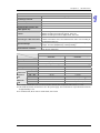
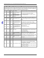
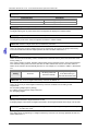
Load cell module
Maximum distance for
connecting a load cell
Maximum output current
Allowable load
Averaging weights
Common-mode rejection ratio
(CMRR @50/60 Hz)
DVP201/202/211LC-SL
Voltage output
100 meters
5 V DC * 300 mA
40~4,010 Ω
100
≥100 dB
Between a digital circuit and the ground: 500 V AC
Between an analog circuit and the ground: 500 V AC
Between an analog circuit and a digital circuit: 500 V AC
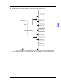
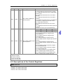
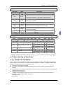
Load cell modules can be connected to the left side of a PLC. The
Connecting to a DVP series PLC modules connected to a PLC are numbered from 100 to 107 according to
the closeness to the PLC.
Operation: 0~55°C (temperature), 5~95% (humidity), pollution degree 2
Operation/Storage
Storage: -25~70°C (temperature), 5~95% (humidity)
International standards: IEC 61131-2, IEC 68-2-6 (TEST Fc)/IEC 61131-2
Vibration/Shock resistance
& IEC 68-2-27 (TEST Ea)
Isolation
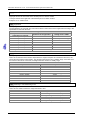
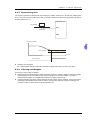
DVP211LC-SL
Electrical specifications for input Electrical specifications for output
terminals
terminals
Input/Output terminal
X0, X1
Y0, Y1, Y2, Y3
Type
Digital input
Transistor
Form
DC (sinking or sourcing)
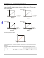
-Specifications
Input current: 24 V DC, 5 mA
Voltage specifications: 5~30 V DC #1
Input impedance
4.7 KΩ
-Maximum switch frequency
10 kHz
1 kHz
Off → On
> 15 V DC
-Action level
On → Off
< 5 V DC
-Response
Off → On
< 20 μs
< 100 μs
time
On → Off
< 50 μs
< 150 μs
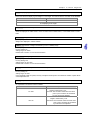
Resistive load
-0.5 A/output (4 A/COM)#2
Maximum
Inductive load
-15 W (30 V DC)
load
Bulb
-2.5 W (30 V DC)
Note: In order to meet DIN 1319-1, an error needs to be less than or equal to 0.05% at 20 °C + 10 K.
#1: UP and ZP should be connected to a 24 V DC power supply. The current that an output terminal consumes
is approximately 1 mA.
#2: In an NPN mode, ZP is used. In a PNP mode, UP is used.
1-3