1
8.0
Installation – page 21
8.6
Fitting the Flue (Cont)
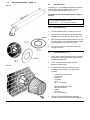
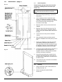
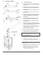
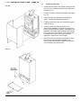
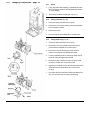
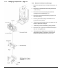
10. Slide the rubber seal over the air duct with the thicker
section outermost (Fig. 25). Align the seal with the end
of the air duct.
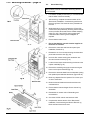
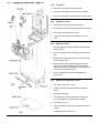
11. Engage uncut end of the flue duct in the flue elbow
using soap solution to ease the engagement (Fig. 26).
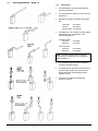
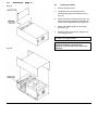
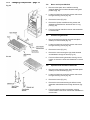
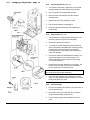
12. Insert the flue duct into the air duct and engage it in the
terminal (Fig. 27).
13. Slide the rubber sleeve over the joint between the air
duct and elbow.
14. Align the clip over the rubber seal. For neatness the
screws on the clip flange should be below the air duct if
possible, providing they remain accessible (Fig. 27).
Secure the clip.
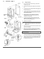
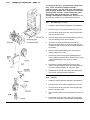
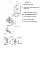
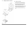
15. Peel the backing paper off the adhesive on the flue
gasket. Fix the gasket to the flue elbow (Fig. 28).
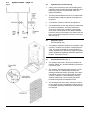
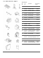
16. Take the flue outlet restrictor, flue spigot and rubber
sleeve from the kit.
17. Insert the outlet restrictor in the fan outlet. Partly fit the
rubber sleeve over the flared end of the flue spigot. Roll
the remainder of the sleeve back over itself.
18. Engage the flared end of the spigot over the fan outlet
and roll the rubber sleeve down to cover the joint
between the spigot and fan outlet.
19. Slide the flue assembly through the hole in the wall.
20. Engage the elbow on to the flue connection on top of
the boiler. Secure with the four screws (Fig. 28).
NOTE: If the flue length is greater than 1 metre then
follow the instructions in the extension kits for the
removal of the flue restrictor.
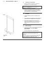
21. Make good between the wall and air duct outside the
building.
22. Fit the circular flue trim outside if required, and if
necessary fit a terminal guard (see Section 7.10 & 7.11
).
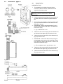
VERTICAL FLUE
1.
2.
Only a flue approved with the Baxi Bahama 100 can be
used.
For information on vertical flues consult the Baxi
Bahama 100 Installer Guide or Notes for Guidance
supplied with the vertical flue pack.