1
USER INSTRUCTIONS
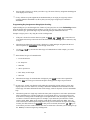
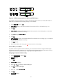
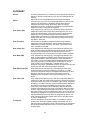
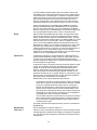
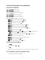
KP-32 KEYPANEL
EKP-32 EXPANSION PANEL
LCP-32 LEVEL CONTROL PANEL
Listen
Headset MENU
Talk
Vol. Sel.
FWD
Mic
.3 2.3 $1'< .3 '$1 .3 7,) .3
™
KP-32
1
2
3
9350-7656-000 Rev A, 12/99
PL
AU TO
2
3
IFB
ISO
PR EFIX
4
5
RE LAY
TY PE
CO PY C W
E-PN L
7
8
EX COP Y
DI SPLAY
MUTE CLR
Call waiting
Listen
5
BACK
1
6
9
MU LT
Headset
4
:.3 :.3
) '$1 .3 .3 6/ .3 0
NU M
SLI ST
PH ONE
Talk
Vol.
0
FU NC
PGM
PROPRIETARY NOTICE
CUSTOMER SUPPORT
The RTS product information and design disclosed herein
were originated by and are the property of Telex
Communications, Inc. Telex reserves all patent,
proprietary design, manufacturing, reproduction, use and
sales rights thereto, and to any article disclosed therein,
except to the extent rights are expressly granted to others.
Technical questions should be directed to:
Customer Service Department
RTS/Telex,
2550 Hollywood Way, Suite 207
Burbank, CA 91505 U.S.A.
Telephone: (818) 566-6700
COPYRIGHT NOTICE
Fax: (818) 843-7953
Copyright 1999 by Telex Communications, Inc. All rights
reserved. Reproduction in whole or in part without prior
written permission from Telex is prohibited.
RETURN SHIPPING INSTRUCTIONS
PROCEDURE FOR RETURNS
UNPACKING AND INSPECTION
If a repair is necessary, contact the dealer where this unit
was purchased.
Immediately upon receipt of the equipment, inspect the
shipping container and the contents carefully for any
discrepancies or damage. Should there be any, notify the
freight company and the dealer at once.
If repair through the dealer is not possible, obtain a
RETURN AUTHORIZATION from:
Customer Service Department
Telex Communications, Inc.
Telephone: (800) 828-6107
Fax: (800) 323-0498
WARRANTY INFORMATION
RTS products are warranted by Telex Communications,
Inc. to be free from defects in materials and workmanship
for a period of three years from the date of sale.
DO NOT RETURN ANY EQUIPMENT DIRECTLY TO
THE FACTORY WITHOUT FIRST OBTAINING A
RETURN AUTHORIZATION.
The sole obligation of Telex during the warranty period is
to provide, without charge, parts and labor necessary to
remedy covered defects appearing in products returned
prepaid to Telex. This warranty does not cover any defect,
malfunction or failure caused beyond the control of Telex,
including unreasonable or negligent operation, abuse,
accident, failure to follow instructions in the Service
Manual or the User Manual, defective or improper
associated equipment, attempts at modification and repair
not authorized by Telex, and shipping damage. Products
with their serial numbers removed or effaced are not
covered by this warranty.
Be prepared to provide the company name, address,
phone number, a person to contact regarding the repair,
the type and quantity of equipment, a description of the
problem and the serial number(s).
SHIPPING TO MANUFACTURER FOR REPAIR
OR ADJUSTMENT
All shipments of RTS products should be made via
United Parcel Service or the best available shipper,
prepaid. The equipment should be shipped in the original
packing carton; if that is not available, use any suitable
container that is rigid and of adequate size. If a substitute
container is used, the equipment should be wrapped in
paper and surrounded with at least four inches of
excelsior or similar shock-absorbing material. All
shipments must be sent to the following address and must
include the Return Authorization.
To obtain warranty service, follow the procedures entitled
"Procedure For Returns" and "Shipping to Manufacturer
for Repair or Adjustment".
This warranty is the sole and exclusive express warranty
given with respect to RTS products. It is the responsibility
of the user to determine before purchase that this product
is suitable for the user's intended purpose.
Factory Service Department
ANY AND ALL IMPLIED WARRANTIES,
INCLUDING THE IMPLIED WARRANTY OF
MERCHANTABILITY ARE LIMITED TO THE
DURATION OF THIS EXPRESS LIMITED
WARRANTY.
Telex Communications, Incorporated
8601 E. Cornhusker Hwy
Lincoln, NE 68505 U.S.A.
Upon completion of any repair the equipment will be
returned via United Parcel Service or specified shipper
collect.
NEITHER TELEX NOR THE DEALER WHO SELLS
RTS PRODUCTS IS LIABLE FOR INCIDENTAL OR
CONSEQUENTIAL DAMAGES OF ANY KIND.
2
End-User License Agreement for Telex® Software
IMPORTANT - Please read this document carefully before using this
product.
THIS DOCUMENT STATES THE TERMS AND CONDITIONS UPON
WHICH TELEX COMMUNICATIONS, INC. (the “COMPANY”)
OFFERS TO LICENSE THE INSTALLED SOFTWARE OR PROGRAM
(“the SOFTWARE”) FOR USE WITH THE PRODUCT IN WHICH IT
WAS INSTALLED. YOU ARE AGREEING TO BECOME BOUND BY
THE TERMS OF THIS AGREEMENT. IF YOU DO NOT AGREE TO
THE TERMS OF THIS AGREEMENT, DO NOT USE THIS PRODUCT.
PROMPTLY RETURN THE PRODUCT TO THE PLACE WHERE YOU
OBTAINED IT FOR A FULL REFUND.
The installed software as supplied by the Company is licensed, not sold, to
you for use only under the terms of this license, and the Company reserves
all rights not expressly granted to you. You own the product or other media
on or in which the Software is originally or subsequently recorded or fixed,
but the Company retains ownership of all copies of the Software itself.
1. License: This license allows you to use the Software for internal purposes
only on a single product in which it was installed.
2. Restrictions: (a) You may not market, distribute or transfer copies of the
Software to others or electronically transfer or duplicate the Software. YOU
MAY NOT REVERSE ENGINEER, DECOMPILE, DISASSEMBLE,
MODIFY, ADAPT, TRANSLATE, RENT, LEASE OR LOAN THE
SOFTWARE OR CREATE DERIVATIVE WORKS BASED ON THE
SOFTWARE OR ANY ACCOMPANYING WRITTEN MATERIALS. (b)
The Software and the accompanying written materials are copyrighted.
Unauthorized copying of the Software, including portions thereof or the
written materials, is expressly forbidden. (c) You understand that the
Company may update or revise the Software and in so doing incurs no
obligation to furnish such updates to you.
3. Limited Warranty: The Company does not warrant that the operation of
the Software will meet your requirements or operate free from error. The
Company DISCLAIMS ALL OTHER WARRANTIES AND CONDITIONS
EITHER EXPRESS OR IMPLIED, INCLUDING THE WARRANTIES OF
MERCHANTABILITY, FITNESS FOR A PARTICULAR PURPOSE AND
NON-INFRINGEMENT OF THIRD PARTY RIGHTS.
4. Limited Liability: The liability of the Company for any claims arising out
of this License based upon the Software, regardless of the form of action,
shall not exceed the greater of the license fee for the Software or $50.
38109-709 Rev A
10/97
3
TABLE OF CONTENTS
DESCRIPTION AND SPECIFICATIONS ............................................................. 6
DESCRIPTION.................................................................................................................... 6
FEATURES......................................................................................................................... 6
OPTIONS............................................................................................................................ 6
SPECIFICATIONS .............................................................................................................. 7
INSTALLATION ................................................................................................... 9
OPTION DIP SWITCH SETTINGS ...................................................................................... 9
ADDRESS SWITCH SETTING .......................................................................................... 10
CONNECTIONS................................................................................................................ 10
BASIC KP-32 OPERATION ............................................................................... 13
SCREEN SAVER OPERATION......................................................................................... 13
SELECTING HEADSET OR SPEAKER............................................................................. 13
LISTEN VOLUME ADJUSTMENTS................................................................................... 13
INTERCOM KEYS AND DISPLAYS .................................................................................. 13
MUTING THE MICROPHONE........................................................................................... 16
CALL WAITING OPERATION ........................................................................................... 16
TELEPHONE OPERATION ............................................................................... 17
RECEIVING A PHONE CALL ............................................................................................ 17
DIALING AND HANGING UP USING THE KP9X KEYPAD SEQUENCES......................... 17
DIALING AND HANGING UP USING THE KP-32 DIALING MENU.................................... 19
KP9X SERIES KEYPAD PROGRAMMING ....................................................... 21
KEYPAD PROGRAMMING, DISPLAY REQUESTS........................................................... 21
KEYPAD PROGRAMMING, ASSIGNING SETUP PAGES................................................. 23
KEYPAD PROGRAMMING, ASSIGNING INTERCOM KEYS ............................................ 24
THE KP-32 MENU SYSTEM .............................................................................. 28
MENU SYSTEM, MENU ACCESS .................................................................................... 28
MENU SYSTEM, DISPLAY MENU .................................................................................... 28
MENU SYSTEM, KEY ASSIGN MENU.............................................................................. 29
KEY OPTION MENU......................................................................................................... 34
SERVICE MENU............................................................................................................... 37
4
GLOSSARY ....................................................................................................... 46
INDEX................................................................................................................. 52
KP9X KEYPAD SEQUENCE QUICK REFERENCE.......................................... 55
KP9X DISPLAY SEQUENCES .......................................................................................... 55
KP9X SETUP PAGE ASSIGNMENT ................................................................................. 55
KEY ASSIGNMENTS USING KEYPAD NUMERIC ENTRY ............................................... 55
KP9X PHONE OPERATION.............................................................................................. 56
KP-32 MENU SYSTEM QUICK REFERENCE................................................... 58
MENU ACCESS................................................................................................................ 58
MENU LIST....................................................................................................................... 58
LIST OF TABLES
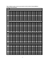
Table 1. Address number vs intercom port numbers for 8-Port Audio I/O Cards (ADAM and
ADAM CS Intercom Systems) ............................................................................................ 54
LIST OF FIGURES
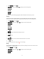
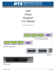
Figure 1. DE9S Intercom Cable Wiring...................................................................................... 11
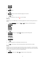
Figure 2. RJ12 Intercom Cable Wiring....................................................................................... 11
Figure 3. Setup page usage for the KP-32 and EKP-32............................................................. 22
Figure 4. LCP-32 correspondence to KP-32 and EKP-32 keys .................................................. 41
Figure 5. Mod ID assignments for the KP-32 and EKP-32 ......................................................... 44
5
DESCRIPTION AND SPECIFICATIONS
DESCRIPTION
TM
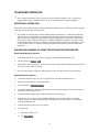
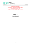
The RTS Model KP-32 Keypanel fits in a standard 19" rack and is 2 rack spaces high. It has 32 lever
keys: 30 keys are for intercom talk/listen assignment; 1 key is for call waiting response; and 1 key is for
headset/microphone/program selection and volume setup. The KP-32 combines all of the programmable
features of the KP9X Series Keypanels and the KP-12 Keypanel. Plus, it adds significant new features such
as digital signal processing and binaural headset operation with left/right assignment of audio signals. The
KP-32 also introduces large, super-bright, long-life fluorescent displays with adjustable brightness control,
making it suitable for all types of ambient lighting from direct sunlight to darkness.
FEATURES
Super-bright, fluorescent displays: Provide much better visibility and useable life than LCD displays. A
display saver mode with programmable scrolling message extends display life and conserves power during
periods of inactivity.
32 lever keys, with 30 keys available for full talk/listen configuration: Doubles the number of channels over
the KP9X series keypanels. Keys support both latching (hands-free) and momentary (push-to-talk)
operation.
Enhanced programming keypad: Provides the complete KP9X keypad sequences, plus new keypad
sequences, plus an extensive scrollable menu system. Menus include helpful prompts to walk the user
through setup.
Only 90 mm deep behind the front panel (approximately 130 mm with connectors): Perfect for consoles,
OB vans, etc.
Digital Signal Processing (DSP): Improves microphone voice activation and limiting. Adds new mixing,
metering, and filtering capabilities.
Binaural (5-pin) Headset Connector: Works with the DSP mixing feature. Lets you independently assign
intercom, microphone, and program audio to left or right headphone. Note: monaural (4-pin) connector
available as an option. For monaural operation, the mixer lets you select which items are monitored in the
headphones.
Easy upgrades: Firmware updates can be received via the internet, for example, and then downloaded to the
KP-32 via the intercom connection. Ready for future communication enhancements, including coax, fiber,
and ISDN. (For further information, search for keyword "firmware" in ADAMedit help.)
OPTIONS
Connector Module: Factory install or easy add-on. Provides connectors for two line-level audio inputs
(program 1 and 2), an unswitched, balanced microphone preamplifier output, an external headset, an
external speaker output, and a foot switch input (for remote switch activation of all "armed" talk keys, or
just one key). Also includes a General Purpose Input / Output (GPIO), with four opto-isolated inputs, two
open-collector outputs, and two SPDT relay outputs. Inputs can activate single keys, groups of keys, or
change setup pages. Outputs can activate external devices from keypanel keys or from GPI inputs.
EKP-32 Expansion Keypanel. Add 32 intercom keys for a total of up to 64 keys (62 intercom keys total).
LCP-32/2 Level Control Panels. Provide easy adjustment of point-to-point and party line listen levels for
individual intercom keys. One LCP-32/2 adjusts the top row of keys, and one adjusts the bottom row. LCP32/2 panels are 1 RU high, 19" wide.
6
SPECIFICATIONS
Microphone Preamplifier
Audio Input Level (at 1 kHz):
Electret Mic:
-42 dB, 150 ohms
Dynamic Mic:
-60 dBm, 150 ohms
Output Level (to matrix):
+8 dBu, ± 0.2 dBu
Max Voltage Gain, Mic to Line:
70 dB, ± 2 dB
Frequency Response:
100 Hz to 10 kHz, ± 2 dB
Tone Generator
Output Level (to matrix):
+8 dBu ± 2 dBu
Output Frequency:
500 Hz
Headphone Amplifier:
Maximum Voltage Gain:
200 dB
Frequency Response:
100 Hz to 10 kHz, ± 2 dB
Headphone Impedance:
8 to 600 ohms
Output Power:
1 W into 50 ohms
Output Voltage Level:
8 volts peak-to-peak (max.)
Sidetone Range:
15 dB
Speaker Amplifier and Speaker
Frequency Response:
100 Hz to 10 kHz, ± 2 dB
Output Power (per amplifier):
4 watts into 4 ohms
Output Voltage Level:
16 volts peak-to-peak (max.)
Volume Control Range:
30 dB
Speaker Rating:
4 watts max
Intercom Input/Output
Input:
Nominal: +8 dBu. Peak: ± 20 dBu max.
Output:
+8 dBu, ± 2 dBu nominal
External Line Input: (Program Input)
Input Level
+8 dBu nominal
General
AC Supply:
External, switching type, 100-240 VAC, 50/60 Hz with locking DIN
connector for attachment to the keypanel and universal IEC
connector for connection to various AC mains cords
Environmental:
Storage:
-40°C to +60°C
Operating:
-10°C to +41°C
Dimensions:
19" wide x 2RU x 3.5" (90 mm) deep
Connectors (Other connector options available)
Panel Microphone Connector
Connector Type
3-circuit, 1/4" phone jack w/threaded metal bushing, compatible w/
RTS MCP5/6
Pin-out
Tip: +Audio and DC bias
Ring: Common
Sleeve: Chassis ground
7
Headset Connector
Connector Type
XLR5 female
Pin-out
Pin 1: Mic low
Pin 2: Mic high
Pin 3: Common
Pin 4: Headphone left high
Pin 5: Headphone right high
Power Input Connector
Type:
5-pin locking DIN
Pin-out
Pin1: Common
Pin2: Common
Pin3: +5VDC, 1.50A Max.
Pin4: -15VDC, 0.150A Max.
Pin5: +15VDC, 0.5A Max.
Intercom Connectors: Parallel-wired DE9S and RJ12 Connectors
Type
DE9S
Pin 1: Data +
Pin 2: Data Pin 3: Audio in (from matrix) shield
Pin 4: Audio out (to matrix) +
Pin 5: Audio out (to matrix) Pin 6: Data shield
Pin 7: Audio in (from matrix) Pin 8: Audio in (from matrix) +
Pin 9: Audio out (to matrix) shield
Type
RJ12
Pin 1: Data Pin 2: Audio in (from matrix) +
Pin 3: Audio out (to matrix) +
Pin 4: Audio out (to matrix) Pin 5: Audio in (from matrix) Pin 6: Data +
Expansion Connector
RJ45
LCP Connector
RJ45
Approvals
UL, CSA, VDE, CE
8
INSTALLATION
OPTION DIP SWITCH SETTINGS
Switch 1: Latch Enable/Disable
Default setting = Open: Enable.
Description: An intercom key can always be turned on for momentary conversation by pressing and
holding the key during the conversation. There is also an electronic latching feature that lets you tap
intercom keys to turn them on or off. This permits convenient hands-free conversation. However it can also
result in a talk circuit being left on unintentionally. For example, a key that talks to a public address system
could be accidentally left on. Or an IFB key (a type of key assignment that is often used by a director or
producer to give instructions to a listener, such as a news anchor during a television broadcast) could
accidentally be left on, causing confusion for the IFB listener. To prevent such accidents, the latching
feature can be turned off.
☞ DIP switch 1 disables latching for the entire keypanel. If you just need to disable latching for selected
keys, leave DIP switch 1 in the "Open" position. Then, disable latching for the desired keys using the
"D" check boxes in the Keypanels / Ports setup screen of ADAMedit.
Switch 2: Key Gain Enable / Disable
Default setting = Open: Enable.
Description: Enables or disables the Key Gain item in the Key Assign menu.
☞ "Key Assign Menu, Key Gain", page 33.
Switch 3: Screen Saver Enable / Disable
Default setting = Open: Enable.
With Screen Saver enabled, the KP-32 will shut off the display and enter a low-power state after a few
minutes of inactivity. The display reactivates instantaneously on incoming call or when the keypanel
operator actuates any control. As with all fluorescent and back-lit LCD displays, some dimming will occur
after many years of operation. Using the screen saver helps maximize the display life.
Switch 4: Call Flash Timeout
Default setting = Open: 15 Second Flash.
Description: Whenever there is an incoming call and there is a talk key assigned to the caller, the talk LED
next to that key will flash. The flash can be set for 15 second timeout, or until the caller's talk key is
released.
Switch 5: Footswitch Enable / Disable
Default = Open: Disabled.
Description: The optional Connector Module has a footswitch (GRP CALL) input. If the footswitch is
enabled (DIP switch 5 set to the "Closed" position), then keys that are latched on will not activate until the
footswitch is closed. Latched keys are indicated by winking green talk LEDs (on time less than off time),
and when the footswitch is activated, the LEDs provide the normal talk-on indication.
☞ See Also, "LED Indications for Intercom Keys", page 13.
9
Switch 6: Not Defined
Default Setting: Open.
Switch 7: Test/Debug
Default Setting: Open.
Switch 8: Test/Debug
Default Setting: Open.
ADDRESS SWITCH SETTING
General Information
In Zeus, ADAM CS, and ADAM Intercom Systems, intercom ports are arranged in groups of 8. All ports in
a group share a common data port. Each KP-32 keypanel is uniquely identified on the data port by the
setting of its Address switch. The method of determining the proper Address switch setting varies for each
intercom system. Use the method for your intercom system as described below. Then set the white pointer
on the Address switch to point to the correct setting.
Address Setting for Zeus
Intercom port connectors on the Zeus back panel are arranged in three groups of eight intercom ports. For
each group, intercom port connectors are labeled ID 1, ID 2, etc. When you connect a KP-32 keypanel to
Zeus, set the Address switch to match the corresponding ID number on the Zeus back panel. Note that
address switch settings 0, and 9 through F are not used.
Address Setting for ADAM CS
Each Audio I/O card contains 1 group of 8 intercom ports. However, the method of breaking out the groups
depends on the type of connectors on the back panel.
ADAM CS with RJ12 or DB-9 back panel: The intercom port connectors are arranged in groups of 8. The
first connector at the left for each group is Address 1, the next is Address 2, and so forth. Note: Address
switch settings 0, and 9 through F are not used.
ADAM CS with 50-pin Telco back panel: Determine the address setting from Table 1, page 52. To use the
table, locate the intercom port number to which the KP-32 will be connected. Then, read across to the
“Address” column to find the Address number. Set the KP-32 Address switch to this number. Note: settings
0, and 9 through F are not used.
Address Setting for ADAM
Each Audio I/O card contains 1 group of 8 intercom ports. Determine the address setting from Table 1,
page 52. To use the table, locate the intercom port number to which the KP-32 will be connected. Then,
read across to the “Address” column to find the Address number. Set the KP-32 Address switch to this
number. Note: settings 0, and 9 through F are not used.
CONNECTIONS
EXP. AND LCP Connectors
Connect from the Exp. connector of the KP-32 to the Expansion 1 connector of an optional EKP-32
Expansion Panel. Use the interconnect cable supplied with the Expansion Panel. The Expansion 2
connector on the Expansion Panel can connect to a second Expansion Panel, but no more than 64 intercom
keys can be operated per intercom port.
10
Each LCP-32 adjusts the listen levels for 16 keypanel keys, and you can connect as many LCP-32 panels as
required to adjust all keys on the KP-32 and on an optional EKP-32 Expansion Panel. An interconnect
cable is supplied with each LCP-32. Connect the first LCP-32 to the LCP connector on the KP-32. Connect
the second LCP-32 to the first LCP-32, and so forth. Note, when arranging LCP-32 panels in an equipment
rack, you should put them directly above or below the keys they will be used to adjust. See also, “Service
Menu, LCP-32”, page 40.
Frame Connector
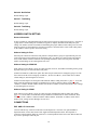
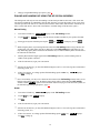
Use either of the Frame connectors (but not both) to connect to an intercom port of the intercom system.
The intercom port you connect to should agree with the address that you set previously. Cable wiring
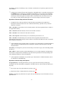
diagrams are shown in Figure 1 and Figure 2.
DE-9P (MALE)
TO KEYPANEL
1
2
6
4
5
9
DE-9S (FEMALE)
TO INTERCOM SYSTEM*
+
-
1
+
-
4
AUDIO TO MATRIX
+
7
AUDIO FROM MATRIX
DATA
7
8
3
2
6
5
9
8
3
CABLE TYPE:
BELDEN 8777
*
IMPORTANT!
When connecting to an ADAM CS back panel, use
only low-profile cable connectors such as AMP
Part No. 747516-3 (Telex Part No. 59926-678)
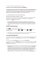
Figure 1. DE9S Intercom Cable Wiring
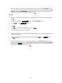
CONTACTS
RJ12 MODULAR PLUG
AMP 5-555042-3 or equivalent
(View from cable entrance)
123456
Use AMP Chordal
Crimp Tool 231648-1
or equivalent
LATCH
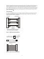
3 TWISTED PAIR TELEPHONE CABLE
PAIR 1: AUDIO TO MATRIX
PAIR 2: AUDIO FROM MATRIX
PAIR 3: DATA
1
2
3
4
5
6
DATA AUDIO FROM MATRIX +
AUDIO TO MATRIX +
AUDIO TO MATRIX AUDIO FROM MATRIX DATA +
1
2
3
4
5
6
Figure 2. RJ12 Intercom Cable Wiring
11
Power Supply Connector
Align and insert the external power supply connector. Tighten the locking ring. Connect a power cord to
the power supply and to an AC power source. The power supply accepts 100-240 VAC, 50/60 Hz.
At power-up, the alphanumeric displays will first show asterisks (****). After a few moments the intercom
key assignments will display. If the keypanel cannot establish communication with the intercom system, all
alphanumeric displays will continue to show asterisks. Check the cable connection.
☞ Power supply connector specifications, page 8.
Headset Connector
A stereo headset may be connected for use along with or in place of the front panel speaker and a separate
microphone. Or, headphones may be connected for use with a separate microphone.
☞ Headset connector specifications, page 8.
Panel Microphone Connector
A panel microphone may be connected for talking, with either the front panel speaker or headphones used
for listening. Accepts MCP5 or MCP6 Panel Microphone. Insert the microphone and rotate the entire
microphone body several turns to lock in place.
☞ Panel microphone connector specifications, page 7.
12
BASIC KP-32 OPERATION
SCREEN SAVER OPERATION
If the KP-32 is set for screen saver operation, the alphanumeric display automatically shuts off after several
minutes of inactivity. The display reactivates on incoming call or when the keypanel operator actuates any
control.
☞ Switch 3: Screen Saver Enable / Disable, page 9.
☞ You can override the normal timeout period for screen saver operation and immediately place the
keypanel in screen saver mode. See "Service Menu, Disply Dim", page 37.
SELECTING HEADSET OR SPEAKER
Tap the Headset / Vol. Sel. key upward. The Vol. Sel. display alternates between +FUV and 6RMT with
each key tap. The Headset LED lights when the headset is selected and is off when the speaker is
selected.
LISTEN VOLUME ADJUSTMENTS
By default, the Vol. control adjusts the listen volume for the speaker or headset, whichever appears in the
Vol. Sel. display. If program inputs are connected and activated, tap downward on the Headset / Vol.
Sel. key to select the desired program source in the Vol. Sel. display (3IO or 3IO). Then, use the Vol.
control to adjust the listen volume. The Vol. control defaults back to the speaker or headset after about one
minute of inactivity of the control.
☞ You can save the volume adjustments to be the power-up defaults using "Service Menu, Save Cfg",
page 44.
INTERCOM KEYS AND DISPLAYS
Alphanumeric Display Indications for Intercom Keys
Upper Case Letters: Upper case letters indicate keys that have any kind of talk assignment, with or without
a corresponding listen assignment. Example: ',5
Lower Case Letters: Lower case letters indicate keys that have only a listen assignment. Example: FKT.
Dashes : Dashes indicate a key that has no talk or listen assignment.
Flashing Alphanumeric Display: This means the key is activated to talk to an IFB, ISO, or TIF.
☞ The flashing alphanumeric display for TIF keys, remote IFB keys, and remote ISO keys can be
disabled by placing a check mark next to "Don't generate tallies for TIF and trunk use" in ADAMedit
(Options menu, Intercom Configuration, Options tab).
LED Indications for Intercom Keys
Talk LED Indications
The talk LED is the lower LED for each key. The talk LED indications are as follows:
Continuous Green: Talk is on and the keypanel operator can be heard at the destination.
13
Continuous Red Talk LED ("In-use"): The key is off, but someone is talking to the destination. This
indication is provided for any local PL, IFB, ISO, or TIF key. It does not apply to remote IFB or ISO keys.
This indication is provided so keypanels operators know when critical director communications are
occurring. If you activate the key, either of two things will happen:
•
If you activate the key and the talk LED turns continuous green, this indicates that you and the other
keypanel operator are both talking to the destination.
•
IFB keys only: If the talk LED flashes red when an IFB key is activated, this indicates that the other
keypanel has a higher IFB priority and you cannot talk at this time.
☞ The red "in-use" indication for TIF keys can be disabled in ADAMedit: In the ADAMedit Options
menu, select Intercom Configuration, then click on the Options tab. Place a check mark next to "Don't
generate talliesfor TIF and trunk use". Be sure to send the change to the intercom system. Note that
this will also disable the flashing alpha display when talking to remote IFBs or ISOs as previously
described.
Flashing Red Talk LED ("Busy"): You cannot talk at this time. This indication occurs when you activate
a local IFB key that is already in-use by a keypanel with a higher IFB priority. It also occurs when you
activate any key assigned to a remote destination, but there are currently no trunks available.
☞ Note: Flashing red is also the intended indication when attempting to talk to a remote IFB while
someone else with a higher trunk IFB priority is already talking. However, this will require ADAM
MC version later than 9.9.x and Trunk MC version later than 7.x.x. As of this writing, these versions
are not implemented. Regardless of the indication provided, you will not be heard at the remote
location if your keypanel has the lower trunk IFB priority. IFB trunk priorities are set in ADAMedit.
(Click the "KP" button on the ADAMedit toolbar to access Keypanels / Ports setup, then click the
"Edit" button, then click the "Advanced" tab. Enter the desired IFB priority in the fields provided. Be
sure to send the change to the intercom system.)
Flashing Green Talk LED (on time equal to off time): There is an incoming call from the destination
assigned to the key. Activate the key to talk back.
☞ The duration of incoming call flash is controlled by DIP switch 4 on the KP-32 back panel. See
"Option Switch Settings", page 9 for further information.
Winking Green Talk LED (on time less than off time): This indicates that a key is ready to talk (key is
on), but requires external footswitch activation to talk.
☞ "Switch 5: Footswitch Enable / Disable", page 9.
Listen LED Indication
The listen LED is the upper LED for each key. The listen LED is green when listen is on.
Intercom Key Operation
Basic Intercom Key Operation
The "up" position of an intercom key activates listen (if assigned). The "down" position activates talk (if
assigned). If there is no talk assignment for an intercom key, the talk position of the key will not activate. If
there is no listen assignment, the listen position will not activate.
For momentary activation of a key press and hold the key. Then, release it when finished.
14
For latching operation (if enabled) tap a key; it will turn on and remain on. Tap the key again to turn it off
when finished.
☞ Latching may be turned off for the entire keypanel by setting DIP switch 1 on the KP-32 back panel to
the Closed position. Latching may be disabled for individual keys on a keypanel using ADAMedit:
Click the KP button on the ADAMedit toolbar to open the Keypanels / Ports setup screen. Select the
intercom port where the keypanel is connected. Place a check mark in the "D" check boxes for any
keys where you want to disable latching. Be sure to send your changes to the intercom system.
Operation of Intercom Keys with Auto Functions
☞ Assignment of keys with auto functions is described in the programming sections that follow.
Descriptions of the auto functions are also contained in the Glossary. Operation of keys with auto
functions is as follows:
Talk + auto follow: Talk and listen can be activated separately. The listen assignment listens to whatever
is assigned to the talk key.
Talk + auto listen: Both talk and listen will activate when talk is activated.
Talk + auto mute: Listen will turn off when talk is activated.
Talk + auto reciprocal: Listen will always be on, and talk may be turned on or off.
Talk + auto table: If an IFB talk key has an auto-table listen assignment, talk and listen can be
independently activated. The listen key listens to whatever is defined as the IFB Listen Source for the IFB
that is assigned to the talk key.
☞ A full explanation of the auto-table feature is beyond the scope of this manual. For further information,
search for "IFB" in ADAMedit help, then read the topics "IFB Auto Table Description" and "IFB
Setup Procedures".
All Call Key: Activating the key will also activate all keys to the left of it (up to, but not including another
all-call key).
Talk + DIM: If a point-to-point key has the DIM function as a level 2 talk assignment, activating the key
will cause the crosspoint levels to diminish for any other intercom ports that are currently listening to the
same destination and that are in the same DIM table.
☞ A full explanation of DIM tables is beyond the scope of this manual. For further information, search
for "dim table" in ADAMedit help.
Operation of Intercom Keys with Options
Group Option Keys: Activating the master key in a key group will activate all keys in that group
according to each key's individual key assignment. Activating a slave key will not affect any other keys in
the group.
☞ Key Groups setup: "Key Option Menu, Key Groups", page 35.
☞ Display Key Groups: "Display Menu, Key Groups", page 29.
Solo Key: Activating a key that has the solo option will cause all other keys to turn off until the solo key is
again turned off.
15
☞ Solo key setup / display: "Key Option Menu, Solo", page 36.
Operation of Intercom Talk Keys with the Speaker DIM Setting
Activating any talk key will cause the speaker or headphone volume at this keypanel to diminish by the
amount specified in the Dim menu item on the Service menu. Note: do not confuse this with the Talk+DIM
auto function previously described (page 15). Talk+DIM affects the speaker or headphones on other
keypanels when a particular talk key is activated on this keypanel. Speaker DIM affects the speaker or
headphone level on this keypanel when any talk key on this keypanel is activated.
☞ For speaker DIM setting, see "Service Menu, Dim", page 37.
Operation of Intercom Keys assigned to TIF Ports
If an intercom key is assigned to talk to an intercom port that is designated as a TIF port in ADAMedit,
placing the key in the talk position will activate the KP-32 dialing menu. See "TELEPHONE
OPERATION", page 17, for further information.
☞ Note: You designate an intercom port as a TIF port by checking the "Port is TIF" check box in
ADAMedit. (In ADAMedit, click the "KP" button on the toolbar to access Keypanels / Ports setup,
then select the intercom port where the TIF s connected, then click the "Edit" button, then click the
"Advanced" tab. Place a check next to "Port is TIF". Remember to send the change to the intercom
system.)
MUTING THE MICROPHONE
Tap the MUTE key to turn microphone muting on or off.
The Vol. Sel. display alternates between +FUV and 0WVG (or between 6RMT and 0WVG) while the
microphone is muted.
☞ While muting is on, you cannot be heard on the intercom, or by anyone on the telephone, or by any
device connected to the mic preamp output of the optional connector module.
CALL WAITING OPERATION
Occasionally, a keypanel may call, and there won’t be a key assigned to talk back to that caller. In this case,
the caller’s name will appear in the Call waiting window. Press down and hold the Call waiting key to
talk back.
To clear a name from the Call waiting window, tap "up" on the Call waiting key.
If a second call is received in the Call waiting window while a caller name is already displayed, the Call
waiting LED will flash red. To answer the second call, tap "up" to clear the first name, then hold the key
down to talk to the second caller.
☞ By default, only the names of callers who are not currently assigned to intercom keys will appear in the
Call waiting window. Alternatively, you can force all caller names to display in the Call waiting
window. This is controlled either by DIP switch 2 on the ADAM Master Controller card or by the
ADAMedit check box titled "Always stack callers in call waiting window". (ADAMedit Options
menu, Intercom Configuration, Options tab. Note: the setting in ADAMedit overrides the DIP switch 2
setting on the Master Controller card.) If your intercom system has mostly keypanels with
alphanumeric displays, we recommend that you do not stack all callers in the Call waiting window.
16
TELEPHONE OPERATION
☞ Note: Telephone operations require an optional TIF-951 Telephone Interface. Also, you must first
assign an intercom key to talk/listen to the TIF. We recommend a talk+auto listen assignment.
RECEIVING A PHONE CALL
When there is an incoming telephone call, the talk LED will flash red next to the KP-32 key that is assigned
to the TIF. Activate the key to answer the call.
☞ The red flash for incoming TIF call is the default operation. Alternatively, a continuous-red talk LED
indication can be provided. This is accomplished by checking the check box "Don't generate tallies for
TIF or trunk use" in ADAMedit (Options menu, Intercom Configuration, Options tab). Note that this
check box also affects other tally indications. For further information, press the F1 key while viewing
the ADAMedit Options tab settings. Under the topic "Don't generate tallies for TIF or trunk use" click
on the "see table" link to view a table containing information about operation with and without tally
indications.
DIALING AND HANGING UP USING THE KP9X KEYPAD SEQUENCES
KP9X Keypad Hang-up Sequence
1.
Turn off the TIF talk key. (Tap "down" to toggle talk off. The talk LED should be off.)
2.
On the keypad, tap PHONE CLR.
3.
Momentarily turn the TIF talk key on, then off. The TIF key talk and listen indicators will turn off and
the TIF-951 "OFF" LED will activate.
☞ You can use the hang up sequence to hang up the TIF even if you did not place or answer the call.
KP9X Manual dial sequence
1.
Activate the TIF listen key. (Tap "up" to toggle listen on. The listen LED should be on.)
2.
Make sure the TIF talk key is off (Talk LED off).
3.
On the keypad, tap CLR PHONE PGM.
4.
Activate the TIF talk key. The talk LED turns green, the "ON" LED at the TIF-951 activates, and you
should hear dial tone at the KP-32.
5.
Dial the telephone number. Digits scroll in the display above the TIF key.
6.
When the far end answers, you can dial additional digits (to access a mail system or automated
response system, etc.). When finished dialing, momentarily turn off the TIF talk key to end dialing
mode (talk LED turns red).
7.
Turn the TIF talk key back on for conversation.
8.
To end the call:
a.
Turn the TIF talk key off.
b.
Tap PHONE CLR.
17
c.
Tap the TIF talk key. The TIF key talk and listen indicators will turn off and the TIF-951 "OFF"
LED will activate. The TIF-951 is now ready for another call.
KP9X Redial Sequence
☞ The last dialed phone number is always stored at the TIF and over-writes any previously dialed phone
number. If several people have access to the TIF, redial may not produce the results that you expect!
1.
Tap the PHONE key to activate dialing mode.
2.
Tap "up" on the TIF key to activate listen.
3.
Tap CLR 0
4.
After the number has dialed, click the PHONE key to end dialing mode.
5.
If the far end answers, tap "down" on the TIF key to activate talk.
6.
Use the KP9X hang-up sequence, page 17, when finished with the call.
0 . The last phone number will redial.
KP9X Autodial Sequences
☞ Unlike the autodial operations using the KP-32 menu system (page 20), which store telephone numbers
locally within the KP-32, the KP9X autodial operations work with telephone numbers that are stored at
the TIF-951. The advantage to saving at the TIF-951 is that many users can access a common set of
stored telephone numbers. A disadvantage is that users can easily over-write important telephone
numbers. Also, telephone numbers at the TIF-951 are stored in volatile memory and will be lost if the
TIF-951 loses power.
Storing an Autodial Number in the TIF-951
1.
Tap the PHONE key.
2.
Tap the TIF talk key to latch it on.
3.
Using the number keys on the keypad, dial the phone number that you want to store. The entire phone
number sequence can have up to 30 digits.
☞ To insert one or more pauses anywhere in the dialing sequence, enter CLR CLR
9 9 for each
pause. A pause may be required, for example, if you need to enter a digit to get an outside line and
your phone system requires a pause before continuing to dial. If you are using credit card dialing,
several pauses may also be required between the phone number and your personal access code.
4.
After dialing the telephone number, click CLR PGM, then enter a two-digit number (01, 02, etc. up to
32) that you will use as the autodial number.
5.
After storing the autodial number, hang up using the KP9X hang-up sequence, page 17.
Dialing an Autodial Number Stored in the TIF-951
1.
Tap the PHONE key to activate dialing mode.
2.
Tap "down" on the TIF talk key to latch it in the on position.
3.
Tap CLR followed by the autodial number (01, 02, etc.).
4.
When finished dialing, click the PHONE key again to exit dialing mode.
18
5.
Hang up using theKP9X hang-up sequence, page 17.
DIALING AND HANGING UP USING THE KP-32 DIALING MENU
The dialing menu will only activate when talking to an intercom port that has the "Port is TIF" check box
activated in ADAMedit. (In ADAMedit, click the "KP" button to access the Keypanels / Ports screen, then
select the port where the TIF-951 is connected, then click the "Edit" button, then click the "Advanced" tab.
Place a check mark next to "Port is TIF". Remember to send this change to the intercom system.)
Manual Dialing
1.
Turn on the TIF talk key. 0CPWCN'KCN displays in the Call waiting window.
2.
Tap the PGM key. 'KCN" displays, and the dial tone should be audible in your speaker or headset.
☞ To hang up at any time after this point: tap the BACK key. +CPI
WR will display, then tap PGM.
☞ While using the phone, any incoming intercom calls to the Call waiting window will go into the call
waiting stack. The caller names will not be displayed, but the Call waiting LED will flash red. You
may either hang up the phone and answer the intercom call, or continue with the phone call and answer
the intercom call afterward.
3.
Dial the phone number. Digits appear in the Call waiting window as you dial. Dialing tones are
audible in the speaker or headset.
4.
If the far end answers, begin your conversation.
☞ After the far end answers, you may dial additional digits (to retrieve voice mail, log onto an automated
answering system, etc.).
5.
If there is no answer, or to hang up when finished talking, tap the BACK key. +CPI WR displays.
Tap PGM to hang up.
☞ Note: Occasionally, you may receive intercom caller names in the Call waiting window while you are
talking on the phone. In this case, the dialing menu options will be cleared from the Call waiting
window, and the +CPI WR option won't be available. Instead of trying to reenter the menu system, use
the "KP9X Keypad Hang-up Sequence", page 17.
Redial
1.
Turn on the TIF talk key. 0CPWCN'KCN displays in the Call waiting window.
2.
Tap the ↓↓ key until 5GFKCN displays.
3.
Tap PGM.
4.
If the far end answers, begin your conversation.
☞ After the far end answers, you may dial additional digits (to retrieve voice mail, log onto an automated
answering system, etc.).
5.
If there is no answer, or to hang up when finished talking, tap the BACK key. +CPI WR displays.
Tap PGM to hang up.
19
☞ Note: Occasionally, you may receive intercom an intercom caller name in the Call waiting window
while you are talking on the phone. In this case, the dialing menu options will be cleared from the Call
waiting window, and the +CPI WR option won't be available. Instead of trying to reenter the menu
system, use the "KP9X Keypad Hang-up Sequence", page 17.
Autodial
☞ Autodial is only available after you have saved autodial numbers. See "Key Option Menu, Auto Dial",
page 34.
1.
Turn on the TIF talk key. 0CPWCN'KCN displays in the Call waiting window.
2.
Tap the ↓↓ key until $WVQ 'KCN displays.
3.
Tap PGM.
4.
Tap ↓↓ to select the desired autodial number, then tap PGM.
5.
If the far end answers, begin your conversation.
☞ After the far end answers, you may dial additional digits (to retrieve voice mail, log onto an automated
answering system, etc.).
6.
If there is no answer, or to hang up when finished talking, tap the BACK key. +CPI WR displays.
Tap PGM to hang up.
☞ Note: Occasionally, you may receive an intercom caller name in the Call waiting window while you
are talking on the phone. In this case, the dialing menu options will be cleared from the Call waiting
window, and the +CPI WR option won't be available. Instead of trying to reenter the menu system, use
the "KP9X Keypad Hang-up Sequence", page 17.
20
KP9X SERIES KEYPAD PROGRAMMING
☞ A summary of the keypad programming sequences is located at the back of the manual for quick
reference.
KEYPAD PROGRAMMING, DISPLAY REQUESTS
Display requests let you view information about the keypanel configuration. You can display information
by two methods: either by entering sequences on the programming keypad, or by scrolling the names of
display requests in the Call waiting window and then selecting the desired display request. The scrolling
method also gives you access to additional features that are not available with the keypad sequences. The
following paragraphs discuss these two methods.
Display Requests Using Keypad Sequences
All display request sequences start with FUNC DISPLAY.
Display Panel ID
FUNC DISPLAY 1 .
This sequence displays the calculated port number. The calculation is based on the data group that the
keypanel is connected to, combined with the Address switch setting on the back of the keypanel. Note that
if the Address switch is incorrectly set, the wrong Panel ID will display.
☞ For futher information about port address calculation, see the "Port" description in the Glossary, page
49.
Tap CLR to quit.
Display Level 2 Talk Key Assignments
FUNC DISPLAY 2 .
This sequence displays all level 2 talk key assignments for about 10 seconds. /GX displays in the Call
waiting window.
Tap CLR to quit.
Display Listen Key Assignments
FUNC DISPLAY 3 .
This sequence displays all listen key assignments for about 10 seconds. /UVP displays in the Call waiting
window.
Tap CLR to quit.
Display Setup Page Assignments
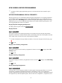
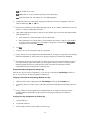
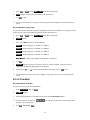
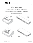
FUNC DISPLAY E-PNL
Currently, there are four setup pages available for each keypanel. Each setup page defines a set of 16 talk
and listen key assignments. Most RTS keypanels have a maximum of 16 keys, so one setup page is
typically assigned to the main keypanel, and is referred to as the "Main" setup page. Additional setup pages
are assigned to any connected expansion panels, and are referred to as "Expansion 1", "Expansion 2", etc.).
21
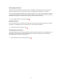
Since the KP-32 requires 2 setup pages, it uses the main page assignments and also one expansion page
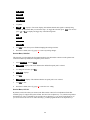
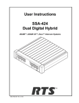
(Figure 3). The EKP-32 uses two additional expansion pages.
Expansion 1 (X1)
L ist en
H ea d se t M E N U
Vo l. Se l.
Ta lk
.3 2. 3 $1'< .3 '$1 .3 7 ,) .3
Main (Mn)
NUM
1
S LI S T
P HO N E
FW D
M ic
™
K P-3 2
C O PY C W
B AC K
PL
A UT O
2
3
I FB
I SO
P RE F IX
5
6
T YP E
E P- N L
7
8
E X C O PY
D SI P LA Y
9
M U LT
MU TE
C all wa itin g
Vo l.
L ist en
5
4
R EL A Y
:.3 : .3
) '$ 1 .3 .3 6/ .3 0 H ea d se t
C LR
0
PG M
F UN C
1
4
Ta lk
2
3
KP-32
Expansion 3 (X3)
L ist en
Ta lk
.3 2. 3 $1'< .3 '$1 .3 7 ,) .3
Expansion 2 (X2)
™
EK P-3 2
:.3 : .3
) '$ 1 .3 .3 6/ .3 0 C all wa itin g
L ist en
Ta lk
EKP-32
Figure 3. Setup page usage for the KP-32 and EKP-32
When you enter the sequence FUNC DISPLAY E-PNL, the Call waiting window displays Mn-1 or
Mn-2, etc. This indicates which setup page is currently being used at the "Main" position. After a few
moments X1-1, or X1-2, etc. displays. This indicates which setup page is currently being used by
expansion 1. Next, if there is an expansion panel connected, X2-1 or X2-2 etc. displays, followed by X3-1
or X3-2 etc. to indicate the setup page usage for expansion 2 and expansion 3.
Tap CLR to quit.
☞ To change the setup page assignments, see "KEYPAD PROGRAMMING, ASSIGNING SETUP
PAGES", page 23.
Test Keys and Displays
FUNC DISPLAY 0
When you enter this sequence, all alpha-numeric displays show a % symbol. Pressing down on any key
(except the Headset / Vol. Sel. key) will cause 2. to display. This verifies operation of the key.
Tapping up or down on the Headset / Vol. Sel. key will cause the display to cycle through the available
selections.
If latching is enabled, tapping up or down on any intercom key, or the Call waiting key, will cause the
corresponding red LED to light. This verifies latching operation and also that the each red LED is OK.
Holding any key in the up or down position will cause the corresponding green LED to light. This verifies
operation of the green LEDs.
Tap CLR to quit.
☞ Note: This sequence is similar to Service Menu, Test Panel, page 44, except that the service menu test
also lets you check the operation of the keypad buttons.
Tone Generator Activation (FUNC-DISPLAY-7)
FUNC DISPLAY 7 .
This sequence activates the keypanel's internal tone generator. You can use the tone generator to check the
audio send and receive paths to and from the matrix. For example, you can assign a talk key on the
keypanel to talk to itself. When you activate the talk key, you should be able to hear the tone from the
keypanel speaker or from a headset.
To turn off the tone generator, press the CLR key.
22
Display Requests Using Scrolling
The display requests described previously can also be accessed using scrolling. Scrolling also offers several
additional features. To use scrolling, tap FUNC DISPLAY followed by ↓↓ or ↑↑ to scroll through the
list of display requests. The display request names will appear in the Call waiting window as follows:
,F PGM: Displays the calculated port number. CLR to quit.
/GX PGM: Displays level 2 talk assignments. CLR to quit.
/UVP PGM: Displays listen assignments. CLR to quit.
1COG PGM: Displays crosspoints closed to this keypanel. CLR to quit.
7[RG PGM: Displays level 1 talk key assignment types. CLR to quit.
0VZ PGM: Displays matrix ID for all level 1 talk assignments. CLR to quit.
7QPG PGM: Turns on tone generator. CLR to quit and turn off tone generator.
(RPN PGM: Displays setup page assignments. 0P=KP-32 bottom row keys. ;=KP-32 top row key.
;=EKP-32 bottom row keys. ;=EKP-32 top row keys.
*CKP PGM: After selecting this item, tap up on any listen key with a point-to-point or party line
assignment. The current listen gain from this keypanel to the intercom port or party line displays in
the Call waiting window. Tap ↓↓ or ↑ ↑ to change the gain. CLR to quit. Use 95UV PGM to
reset all gains.
95UV PGM: Reset all port / party line gains to 0dB.
$UIP PGM: Displays a list of key assignments that are set up for this keypanel, but not currently
accessible. This includes talk level 1 assignments on setup pages that are not currently assigned, and
any key assignment that might be obscured by the call-waiting window. You can scroll through the
list using the ↓↓ ↑ ↑ keys. Then use the Call waiting key to talk to any of the listed destinations.
7GUV PGM: Test keys and displays. CLR to quit.
9ZZZ : Display keypanel firmware version. CLR to quit.
KEYPAD PROGRAMMING, ASSIGNING SETUP PAGES
1.
Tap the E-PNL key.
2.
Select one of the four setup pages: tap 1 , or 2 , etc.
3.
Tap any key in the row of keys where you want to assign the setup page.
Notes
•
The same setup page cannot be assigned in more than one place. If a setup page is already assigned
somewhere else, you must clear or change that assignment first. With the exception of the main row
assignment, you can clear any page assignment from a row of keys by entering E-PNL 0 PGM, then
pressing any key in the row.
•
If you cannot change the setup page assignments for a particular keypanel, this feature may be
restricted in ADAMedit (Keypanels / Ports screen, Edit button, Setup tab, Setup Page Options).
23
☞ To display setup page assignments at any time, see "Display Setup Page Assignments", 21.
KEYPAD PROGRAMMING, ASSIGNING INTERCOM KEYS
General
There are three methods to assign intercom keys with keypad programming. These methods are
summarized below and explained on the following pages.
•
Key Assignment using Keypad Numeric Entry: Using this method, you enter the panel number, party
line number etc. that you wish to assign to a key. This method requires that you know the number (not
the name) of the port, party line etc. that you wish to assign. Since most users do not have access to
this information, this method of key assignment is not recommended.
•
Key Assignment by Copying an Assignment: Using this method, you can copy an assignment from one
key to another. You can also use this method to transfer an incoming call to a talk key and/or listen
key.
•
Key Assignment using Alpha Scrolling: Using this method, you scroll through lists of alpha names in
the Call waiting window and select the name of the panel, party line etc. that you want to assign.
Then you copy that name to a key. If descriptive names have been assigned (using the intercom system
configuration software) alpha scrolling is easiest to use.
Assigning Keys Using Keypad Numeric Entry
☞ Each programming step must be completed within 4-5 seconds. Otherwise, the programming sequence
will automatically quit.
General Procedure
1.
For talk level 2 assignment only: Tap 0
2.
Select the key assignment type:
0 . Otherwise, skip this step.
NUM Intercom port.
PL Party line.
AUTO Auto function.
FUNC SLIST Special list.
FUNC IFB IFB
FUNC ISO Camera ISO
FUNC RELAY Relay or GPI output.
3.
Auto function assignment only: Tap an additional number to select the desired auto function:
1 Auto listen (listen keys only)
2 Auto follow (listen keys only)
3 Auto mute (listen keys only)
4 Auto reciprocal (listen keys only)
24
5 All call (talk level 1 only)
6 DIM (talk level 2 only, for point-to-point key, must enter 00 first)
7 Auto table (listen only, when talk level 1 is an IFB assignment)
4.
Trunked intercoms only: (Skip when assigning auto functions or local key assignments.) Select an
intercom matrix (tap 1 , or 2 etc.).
☞ Intercom system numbers are the numbers that appear in the “Icm” column in CStrunk when you select
“Names” or “Setup” from the Intercoms menu.
5.
(Skip when assigning auto functions.) Tap one or more number keys to select the desired port number,
party line number, etc:
a.
If the destination is in the local matrix, just enter the number.
b.
If the destination is in a remote matrix, you must always enter exactly 3 digits for a port number,
or exactly 2 digits for anything else. For example, to assign port 1 you must enter 0 0 1 ;
for party line 1 you must enter 0 1 .
6.
Tap PGM.
7.
Tap down on a key to assign talk. Tap up to assign listen.
☞ If a key will not accept an assignment, the destination that you are trying to assign may not be scrolling
enabled in ADAMedit. Or, the key that you are trying to assign may be restricted in ADAMedit.
☞ Auto functions are always assigned in the local intercom system, even when used with keys assigned
to a remote intercom system. For example, you can program a talk key to talk to a remote party line
and then program the listen key using auto-listen on the local intercom. Pressing the talk key
automatically activates listening for the remote party line.
Programming Key Assignments Using Copy
There are two ways to copy key assignments: 1) you can copy a call from the Call waiting window to a
key; or 2) you can copy one key's assignment to another key.
Copying a Call from the Call waiting Window to a Key
1.
While the caller’s name is displayed in the Call waiting window, tap the COPY CW key.
2.
Tap the key where you want to copy to. The name of the caller should appear in the display above the
key.
☞ If a key will not accept an assignment, the destination that you are trying to assign may not have
scrolling enabled in ADAMedit. Or, the key that you are trying to assign may be restricted in
ADAMedit.
Copying One Key Assignment to Another Key
1.
Tap the FUNC key.
2.
Tap the EX COPY key.
3.
Press the talk or listen key from which you wish to copy.
25
4.
Press the talk or listen key to which you wish to copy. The name of the key assignment should appear
in the display above the key.
☞ If a key will not accept an assignment, the destination that you are trying to assign may not have
scrolling enabled in ADAMedit. Or, the key that you are trying to assign may be restricted in
ADAMedit.
Programming Key Assignments Using Alpha Scrolling
Alpha scrolling lets you scroll through a list of names of ports, party lines etc. in the Call waiting window.
Once the desired name is displayed in the window, you can copy it to a key. There are four scrolling
modes: intercom, type, prefix and single-step. The following example demonstrates their use.
Example: Assign a port to a key using the various scrolling modes.
1.
If the port is located in a remote intercom system, tap FUNC ↑↑ or FUNC ↓↓ to enter intercom
scroll mode and scroll up or down the list of intercoms in the Call waiting window. Otherwise, skip
to step 2.
2.
When the desired intercom system name is displayed, or when making an assignment in the local
intercom system, tap FUNC TYPE to activate type scroll mode.
3.
Use the ↑↑ or ↓↓ keys to locate the desired type of communication. In this example, you would
scroll to “P-P”.
☞ Abbreviations for types of communication:
• P-P: Point-to-Point
• PL: Party Line
• IFB: IFB
• SPCL: Special List
• RLY: Relay or GPI output.
• ISO: ISO
4.
When the desired type of communication is displayed, press PGM to retrieve the requested list.
Pressing PGM also exits type scroll mode and places the keypanel in single-step scroll mode.
☞ In some cases, “WAIT” may display briefly while the requested list is being retrieved. "N/A" may
display if there is no list. In this case, scrolling is disabled in ADAMedit for all destinations of the
selected type. For further information about scroll settings, search for keyword "scroll" in ADAMedit
help.
5.
When the keypanel is in single-step scroll mode it may take a long time to scroll to the desired name
(this is particularly true of point-to-point lists). To speed up the process, you can use prefix scroll
mode. Prefix scrolling mode scrolls through a list in alpha-numeric order, but displays only the first
occurrence of each two-character prefix. For example, if your intercom system had users CAM1,
CAM2, CAM3, DIR1, DIR2; prefix scrolling would display CAM1 followed by DIR1. Once you
locate a desired two-character prefix using prefix scroll, you can switch back to single-step scrolling
to make your final selection. Tap PREFIX to enter prefix scroll mode, then use the ↑↑ ↓↓ keys to
scroll. When you locate a name with the same first two characters as the name you are looking for, tap
the PGM key to return to single-step scrolling mode.
26
6.
In single-step mode, use the ↑↑ ↓↓ keys to make your final intercom port selection.
☞ If you cannot locate the destination that you are looking for, it may not have scrolling enabled in
ADAMedit.
7.
Copy the selected port to a talk or listen key:
a.
Tap COPY
b.
Tap down on an intercom key to assign talk, or tap up to assign listen.
Clearing a Key Assignment
There are two ways to clear a key assignment:
Method 1: Clearing the Call waiting Window and Copying it to a Key
1.
Clear the Call waiting window, if necessary, by tapping up one or more times on the Call waiting
key.
2.
Tap the COPY CW key.
3.
Tap the key that you want to clear. Tap up to clear listen, down to clear talk.
☞ If a key will not clear, it is probably restricted using the "R" check box in ADAMedit.
Method 2: Copying a Blank Key Assignment to the Key that You want to Clear
1.
Tap the FUNC key.
2.
Tap the EX COPY key.
3.
Tap an unassigned key.
4.
Tap the key that you want to clear. Tap up to clear listen, down to clear talk.
☞ If a key will not clear, it is probably restricted using the "R" check box in ADAMedit.
27
THE KP-32 MENU SYSTEM
☞ A chart of the menu system is located at the back of the manual for quick reference.
MENU SYSTEM, MENU ACCESS
1.
Clear all names from the Call waiting display (if not clear) by tapping "up" one or more times on the
Call waiting key.
2.
Tap MENU to activate the menu system.
3.
Press ↓↓ to scroll forward through the list of menus. Press ↑ ↑ to scroll back.
4.
Tap FWD or PGM to enter a menu. Tap BACK to exit a menu.
5.
Within a menu:
• Press ↓↓ or ↑ ↑ to scroll.
• Tap FWD or PGM to select an item.
• Tap BACK to cancel a selection or to go back to the previous menu level.
MENU SYSTEM, DISPLAY MENU
Use this menu to display information about the keypanel configuration.
Display Menu, Asgn Type
Displays the talk level 1 assignment types for all keys. Abbreviations for the key assignment types appear
in the alphanumeric displays as follows:
•
P-P: Point-to-point talk key.
•
PL: Party line talk key.
•
IFB: IFB talk key.
•
SPCL: Special list talk key.
•
RLY (System relay): The key activates a GPI output at the intercom frame, or a relay output at a UIO256 or FR9528 frame.
•
ISO: Camera ISO talk key.
•
UPL: UPL resource key.
•
AC: All-call key.
☞ For descriptions of the various key assignment types, see the "GLOSSARY", page 46.
Display Menu, Chans On
Displays an alpha list, in the Call waiting window, of all intercom ports that currently have talk
crosspoints closed to this keypanel. Chans On is typically used to locate an open mic or other open audio
source that needs to be shut off. The most likely cause is typically a talk key that has been left on at some
28
keypanel. In this case, use the ↓↓ and ↑ ↑ keys to scroll through the list of names. You can then press
the Call waiting key to ask the person at the other end to turn off their talk key.
Display Menu, Key Groups
Use the ↓↓ or ↑ ↑ key to select Group 1, Group 2, etc. Then press FWD or PGM to display the group.
The talk and listen LEDs of the master key will be lit red and the talk and listen LEDs for the slave keys
will be lit green.
☞ Key Groups setup: Key Option Menu, Key Groups, page 35.
Display Menu, Level 2
Displays the talk level 2 assignments for all keys.
☞ Talk Level 2 Description, page 51.
Display Menu, Listen
Displays the listen assignments for all keys.
Display Menu, Matrix
Displays the intercom system name for all talk level 1 key assignments. In non-trunked intercom systems,
the intercom system name is always LOCL (local). In trunked intercom systems, intercom system names
are created in CStrunk (Intercoms menu, Names.)
☞ Trunking Description, page 51.
Display Menu, Panel ID
Panel ID displays the calculated port number that the keypanel is connected to. The calculation is based on
the data group that the keypanel is connected to, along with the Address switch setting on the keypanel. If
the Address switch is incorrectly set, the wrong Panel ID will display. Panel ID also displays the port alpha
in brackets if the port is not scroll restricted.
☞ ADDRESS SWITCH SETTING, page 10.
Display Menu, Version
Displays the firmware version of the keypanel.
☞ For firmware upgrades, contact your intercom system dealer. The KP-32 firmware can be upgraded
from ADAMedit. In ADAMedit Help, search for "firmware update".
MENU SYSTEM, KEY ASSIGN MENU
Use this menu to assign intercom keys, to adjust listen levels for point-to-point keys and party line keys,
and to assign setup pages.
General Procedure to use the Key Assign Menu
1.
Clear the Call waiting window if necessary, by tapping upward one or more time on the Call
waiting key.
29
2.
Tap Menu
3.
Tap ↓↓ to scroll down to the .G[ $UUKIP menu.
3.
Tap PGM or FWD to enter the menu.
☞ If you do not have a trunking intercom system, skip to step 5.
4.
5.
Remote key assignment only (trunking systems only): If your intercom system is configured for
trunking, 0CVTKZ displays in the Call waiting window. You must select a remote intercom matrix
before assigning intercom keys to destinations in that matrix. You do not need to select an intercom
matrix if you are assigning keys in your own intercom system. Also, do not select an intercom matrix
if you are assigning auto functions or setup pages, or if you are changing listen gains for remote pointto-point keys or remote party line keys. Select a matrix as follows:
a.
Press FWD or PGM to access the Matrix list.
b.
Press ↓↓ o r ↑↑ , to locate the desired matrix.
c.
Press FWD or PGM to select a matrix. Wait may display while the scroll lists for that matrix are
loading.
3VVQ3V should now display in the Call waiting window (both for local and remote key
assignment). This is the list of available point-to-point key assignments. Press ↓↓ or ↑↑ to select a
different list as follows:
3VVQ3V: Assign a key to talk/listen to another intercom port.
3CTV[ /KPG: Assign a key to talk/listen to a party line.
,)%: Assign a key to talk/listen to an IFB.
6REN /KUV: Assign a key to talk/listen to a special list.
6[U 5GNC[: Assign a key to activate a relay or GPI output.
&COGTC ,62: Assign a key to talk/listen to an ISO.
83/ 5GUTE: Assign a key to activate a UPL resource.
$WVQ )WPE: Assign an auto function to a key. (If you select this item, skip the rest of this procedure
and go to "Key Assign Menu, Auto Func", page 32.)
.G[ *CKP: Adjust the listen gain for a key that already has a point-to-point or party line assignment.
(If you select this item, skip the rest of this procedure and go to "Key Assign Menu, Key Gain", page
33.)
5GUGV 9QNU: Restore the default listen level for keys that have a point-to-point or party line
assignment. (If you select this item, skip the rest of this procedure and go to "Key Assign Menu, Reset
Vols", page 33.)
6GVWR 3CIG: Change the setup page assignments. (If you select this item, skip the rest of this
procedure and go to "Key Assign Menu, Setup Page", page 34.)
6.
Tap PGM or FWD to select a list. In some cases :CKV may display while the requested list is
uploaded from the intercom system.
7.
When the requested list is displayed, press ↓↓ or ↑↑ , to locate the desired assignment.
30
8.
Tap PGM or FWD to select the assignment.
9.
7CNM /XN should now display in the Call waiting window. Press ↓↓ or ↑↑ if necessary to
select a different option. Options are as follows:
• Talk Lvl 1: Assigns only talk level 1. Leaves the listen assignment as is.
• Listen: Assigns only listen. Leaves the talk assignment as is.
• Talk + AF: Assigns talk level 1, with auto-follow listen.
• Talk + AL: Assigns talk level 1, with auto-listen.
• Talk + AM: Assigns talk level 1, with auto-mute listen.
• Talk + AR: Assigns talk level 1, with auto-reciprocal listen.
• Talk Lvl 2: Assigns talk level 2.
If you attempt to assign talk level 2 to a key and there is no talk level 1 assignment, your assignment will
go on talk level 1.
If you change the talk level 1 assignment for a key that also has a talk level 2 assignment, the talk level 2
assignment will be erased.
10. Tap PGM or FWD to select one of the previously listed items.
11. 7CR .G[ should now display.
12. Tap an available intercom key. Tap down for any kind of talk key assignment. Tap up for a listen-only
key assignment.
• If you assign any type of talk key, the assignment name will appear in the alphanumeric display
above the key.
• If you add a listen assignment to an existing talk assignment, the listen assignment will appear
briefly in the alphanumeric display to confirm the assignment. Then the talk assignment will
reappear.
• If you assign a key that is listen only, the assignment name will appear briefly in upper-case
letters, then will change to lower-case letters.
13. This completes the key assignment procedure. Refer to any notes below regarding the various key
assignment types.
☞ When reassigning keys remember to remove any Chime, Solo, or Key Group options if they will not
be needed for the new key assignment. Chime setup, page 35. Solo setup, page 36. Key Groups:
Display, page 29; setup, page 35.
Key Assign Menu, Matrix
Matrix appears only for trunked intercom systems. You must select a remote intercom matrix before
assigning intercom keys to destinations in that matrix. You do not need to select matrix to assign keys to
destinations in your own matrix. You also do not need to select a matrix when assigning an auto function to
a key.
31
Key Assign Menu, Pt-to-Pt
Assigns a key that talks or listens to another intercom port. Note that some pt-to-pt destinations may be
non-keypanel devices that cannot activate talk and listen paths. Therefore, if you want full communication,
you may need to assign both talk and listen on the key.
Key Assign Menu, Party Line
Assigns a key that talks and/or listens to a party line. The key will have no effect until members have been
assigned to the party line in ADAMedit. Note that party lines members are usually non-keypanel devices
that cannot activate talk and listen paths. Therefore, if you want full communication with the party line, you
will need to assign both talk and listen on the key. If all communications will normally be 2-way, you may
wish to assign the key as Talk + auto listen.
Key Assign Menu, IFB
☞ By default, all IFBs are restricted and you will see 1QV
$XCKN when you attempt to select this item.
To see IFBs you must check the appropriate Scroll Enable check boxes in ADAMedit.
Key Assign Menu, Spcl List
Assigns a key that talks and/or listens to a special list. The key will have no effect until members have been
assigned to the special list in ADAMedit. Note that some or all special list members may be non-keypanel
devices that cannot themselves activate talk and listen paths. Therefore, if you want full communication
with all members of the special list, you may need to assign both talk and listen on the key.
Key Assign Menu, Sys Relay
Sys Relay refers to any of several types of control devices that can exist in the intercom system, including:
•
The 8 GPI outputs from an ADAM Frame (J11 on the XCP-ADAM-MC Breakout Panel).
•
The 8 GPI outputs of an ADAM CS frame (J903 on the ADAM CS back panel).
•
The relay outputs of an FR9528 Relay Frame (RELAY OUTPUTS connector on the FR9528 back
panel).
•
The 16 GPI outputs of a UIO-256 Universal Input/Output Frame (J5 on the UIO-256 back panel).
Key Assign Menu, Camera ISO
☞ By default, all ISOs are restricted and you will see 1QV
$XCKN when you attempt to select this item.
To see ISOs you must check the appropriate Scroll Enable check boxes in ADAMedit.
Key Assign Menu, UPL Resrc
☞ By default, all UPL resources are restricted and you will see 1QV
$XCKN when you attempt to select
this item. To see UPL resources you must check the appropriate Scroll Enable check boxes in
ADAMedit. (In the ADAMedit System menu, select UPL Resources. Then enter check marks in the
appropriate Scroll Enable boxes.)
Key Assign Menu, Auto Func
1.
Press FWD or PGM to select auto functions in the Key Assign menu. Then press ↓↓ o r ↑↑ to
locate the desired auto function as follows:
32
• AutoFollow (AF, for listen keys only)
• Auto Listn (AL, for listen keys only)
• Auto Mute (AM, for listen keys only)
• Auto Recip (AR, for listen keys only)
• All Call (AC, for talk level 1 only)
• Dim ( Dim Table function, for talk level 2 on point-to-point keys only)
2.
Press FWD or PGM to select the desired auto function.
3.
7CR .G[ displays. Tap an intercom key to assign the selected auto function. Tap up to assign all
auto functions except All Call or DIM. Tap down for All Call or DIM.
☞ If the assignment is successful, the abbreviation for the auto function will appear in the alphanumeric
display for that key. However, if you try to assign an auto function to a key that already has that auto
function assigned, the assignment will be ignored. The assignment will also be ignored if scroll enable
for auto functions has been disabled in ADAMedit, or if the key you are trying to assign has been
restricted in ADAMedit.
☞ You can tap CLR to exit and return to normal operation, or tap BACK to return to the auto function
menu and make more assignments.
☞ Trunked intercom systems: Do not select a matrix before assigning auto functions. All auto functions
are assigned using the local matrix menus.
☞ You do not need to run Save Cfg to store auto function assignments. These are stored in the intercom
system.
☞ For descriptions of the auto functions, see "GLOSSARY", page 46.
Key Assign Menu, Key Gain
Use this menu item to adjust the listen gains for point-to-point or party line keys. The key that you want to
adjust must already have a point-to-point or party line listen assignment.
1.
Press FWD or PGM to select .G[ *CKP in the Key Assign menu.
2.
7CR .G[ displays. Tap "up" on the key that you want to adjust.
3.
The current listen level displays in the Call waiting window.
4.
Press ↓↓ o r ↑↑ to change the listen level.
5.
You may tap additional point-to-point or party line keys to change their listen levels. Or, tap CLR to
quit.
☞ You do not need to run Save Cfg to store key gain changes. These are stored in the intercom system.
Key Assign Menu, Reset Vols
Use this menu item to simultaneously reset gains for all point-to-point or party line keys.
33
1.
Press FWD or PGM to select 5GUGV 9QNU in the Key Assign menu.
2.
'QPG displays. All key gains are now reset to the default level.
3.
Tap CLR to quit.
☞ You do not need to run Save Cfg after resetting key gains. These settings are stored in the intercom
system.
Key Assign Menu, Setup Page
Use this menu item to change the setup page assignments on the KP-32 or EKP-32. One setup page is used
for the top row of keys, and another setup page is used for the bottom row.
1.
Press FWD or PGM to select 6GVWR 3CIG in the Key Assign menu.
2.
3CIG displays.
3.
Press ↓↓ o r ↑↑ to select any of the following:
3CIG : Assign setup page 1 to the KP-32 or EKP-32.
3CIG : Assign setup page 2 to the KP-32 or EKP-32.
3CIG : Assign setup page 3 to the KP-32 or EKP-32.
3CIG : Assign setup page 4 to the KP-32 or EKP-32.
&NGCT 3CIG: Clear a page assignment from the KP-32 or EKP-32.
4.
Tap PGM.
5.
7CR .G[ displays. Tap any key in the row where you want to assign the setup page. The key
assignments for that page should appear in the displays.
6.
You can press ↓↓ o r ↑↑ to select and assign another setup page. Or, tap CLR to exit.
☞ You do not need to run Save Cfg to store changes to setup pages. These are stored in the intercom
system.
KEY OPTION MENU
Key Option Menu, Auto Dial
Use this menu item to store auto dial numbers.
1.
Select $WVQ 'KCN, then tap PGM.
2.
3JQPG" displays.
3.
Begin tapping number keys. The numbers will scroll in the Call waiting window.
☞ To insert a pause at any time, tap
CLR 9
9 . For example, you may have to insert a pause after
dialing 9 to get an outside line.
4.
Tap FWD. (Do not tap PGM!)
34
5.
$'KCN displays (store auto dial number 1). To store a different auto dial number, press ↓↓ or
6.
Tap PGM.
7.
;; UCXGF displays (where XX = the auto dial number you selected).
8.
Run Service Menu, Save Cfg, page 44, to store auto dial numbers.
↑ ↑ to select the desired auto dial number.
Key Option Menu, Chime
You can add a chime tone to any key for incoming call announcement. The chime tone will activate for
about 5 seconds after a call is received.
1.
Select &JKOG, then tap PGM.
2.
Tap any keys where you want to add a chime tone. Both LEDs will light red for the selected keys.
3.
Tap CLR to exit.
4.
Run Service Menu, Save Cfg, page 44, to store Chime settings.
☞ The chime option will continue on a key even if you change the key assignment.
Removing the chime option from a key
Repeat the procedure to add chime, but tap any keys where the LEDs are lit red to turn them off. Run Save
Cfg to store the changes.
Key Option Menu, Key Groups
You can set up a key group, so that when you activate one key (the master key) all keys in the group will
activate. Up to 4 key groups can be set up.
1.
Select .G[ *TQWRU, then tap PGM.
2.
*TQWR displays. To select a different group, press ↓↓ or ↑ ↑ .
3.
Tap PGM.
4.
7CR 0CUVGT displays. The master key is the key that you will press to activate the group.
5.
Tap the intercom key that you want to use as the master. Both LEDs next to the key will light red.
6.
After you select the master key, 7CR 6NCXGU displays. Slave keys are the keys that will activate
along with the master key.
7.
Tap one or more keys to select them as slave keys. Both LEDs will light green for each key that is
selected. You can tap a key again to remove it from the key group.
8.
Tap CLR when finished.
9.
Activating the master key should now cause it and all slave keys to activate. The LEDs for each key
will activate according to the current key assignment for that key.
10. Run Service Menu, Save Cfg, page 44, to store Key Group settings.
☞ Key group settings will continue on keys even if you change the key assignments.
35
Clearing a key group
1.
Select .G[ *TQWRU, then tap PGM.
2.
*TQWR displays. To select a different group, press ↓↓ or ↑↑ .
3.
Tap PGM.
4.
7CR 0CUVGT displays.
5.
Tap the current master key. The LEDs will remain lit red.
6.
After you tap the master key, 7CR 6NCXGU displays.
7.
Tap all the keys where the LEDs are lit green. This will turn the LEDs off.
8.
Tap CLR when finished.
9.
The key group is now cleared.
10. Run Service Menu, Save Cfg, page 44, to store the cleared key group setting.
Key Option Menu, Solo
A solo key will cause all other keys to turn off when activated. You can assign one solo key.
1.
Select 6QNQ, then tap PGM.
2.
7CR .G[ displays.
3.
Tap a key. Both LEDs for the key will light red to confirm the assignment. Tap the key again if you
made a mistake and want to remove the assignment.
4.
Tap CLR when finished.
5.
Activating the solo key should now cause all other activated keys to turn off. The keys will turn back
on again when you turn off the solo key.
6.
Run Service Menu, Save Cfg, page 44, to store the Solo setting.
☞ The solo option will continue on a key even if you change the key assignment.
Removing the solo key option
1.
Select 6QNQ, then tap PGM.
2.
The LEDs for the solo key will be lit red.
3.
Tap the solo key to turn off the LEDs.
4.
Tap CLR to exit.
5.
The solo key is now cleared.
6.
Run Service Menu, Save Cfg, page 44, to save the change.
36
SERVICE MENU
Service Menu, Dim
This item causes the speaker or headphone level to diminish by a specified amount whenever a talk key is
activated.
1.
Select 'KO, then tap PGM.
2.
6RGCMGT displays. To select headset, press ↓↓ .
3.
Tap PGM.
4.
By default, F% displays for speaker, and F% displays for headset. This is the default amount of
dimming.
5.
Press ↓↓ to increase the amount of dimming. Press ↑↑ .to decrease it.
6.
Tap CLR to exit when finished.
9.
The new dimming level is now set.
10. Run Service Menu, Save Cfg, page 44, to store the Dim setting.
Service Menu, Disply Dim
This item adjusts the alphanumeric display settings.
1.
Select 'KURN[ 'KO, then tap PGM.
2.
'KURN 2HH displays
3.
Press ↓↓ or ↑↑ .to select any of the following:
'KURN 2HH Turns off the display. Any incoming call, or control movement, will reactivate the
display.
'KO Possibly a better choice when the ambient light level is low. Uses less power and increases
display life.
1QTOCN Default medium brightness setting.
%TKIJV Good when ambient light is bright.
0CZKOWO Recommended only for very bright ambient light, such as outdoors. Uses maximum
power and decreases display life.
6ET 6CXGT Overrides the normal screen saver timeout period and immediately places the
keypanel in screen saver mode. Normal display operation resumes if there is an incoming call or if the
user actuates any control.
☞ For settings which change the operating brightness, run Service Menu, Save Cfg, page 44, to store the
setting.
Service Menu, DSP Func
This item accesses the digital signal processing features.
37
1.
Select '63 )WPE, then tap PGM.
2.
)KNVGTKPI displays. Press ↓↓ or ↑↑ .to display any of the following items:
)KNVGTKPI
*CVKPI
0GVGTKPI
0KZKPI
3.
Refer to one of the following paragraphs for further information on the item that you select.
Filtering
Filtering lets you add a 19.2 kHz notch filter to one or more audio sources. This can be useful in a few
cases when the keypanel data port signal is being heard in the audio line due to cable routing problems.
1.
Select )KNVGTKPI, then tap PGM.
2.
0KETQRJQPG displays. Press ↓↓ or ↑↑ .to display any of the following items:
0KETQRJQPG
0CVTKZ
3TQITCO 3TQITCO 3.
Tap PGM.
4.
→1QPG displays to indicate that no filtering is selected.
5.
Press ↓↓.
6.
1QVEJ displays.
7.
Press PGM.
8.
→1QVEJ displays. The arrow indicates that the notch filter is now selected.
9.
Tap CLR to exit.
10. Run "Service Menu, Save Cfg", page 44, to save the change.
Gating
Gating minimizes or eliminates background noise problems by shutting off an audio source when the sound
level drops below a certain threshold.
1.
Select *CVKPI, then tap PGM.
2.
0KETQRJQPG displays. Press ↓↓ or ↑↑ .to display any of the following items:
0KETQRJQPG
0CVTKZ
38
3TQITCO 3TQITCO 3.
Tap PGM.
4.
*CVKPI displays.
5.
Tap PGM.
6.
→*CVKPI displays. The arrow indicates that gating is now selected.
7.
Tap CLR to exit.
8.
Run "Service Menu, Save Cfg", page 44, to save the change.
Metering
Metering lets you use the Vol. display as an LED bar graph meter to monitor an audio signal for about 1
minute.
1.
Tap PGM. 0KETQRJQPG displays. Press ↓↓ or ↑↑ .to display any of the following items:
0KETQRJQPG
0CVTKZ
3TQITCO 3TQITCO 2.
Tap PGM.
3.
0GVGT 0KE displays. Press ↓↓ or ↑↑ .to display any of the following items:
0GVGT 0KE
0GVGT 0VZ
0GVGT 3IO
0GVGT 3IO
3.
Tap PGM.
4.
The Vol. bar graph is now monitoring the selected audio source.
5.
Tap CLR to exit metering, or allow the metering function to timeout after about 1 minute.
Mixing
Mixing lets you route selected audio signals to the intercom system, to the speaker, or to the left or right
headphone when using a headset. By default, the microphone signal is routed to the matrix, and the matrix
signal is routed to the speaker and to the left and right headphones.
1.
Tap PGM.
2.
7Q 0CVTKZ displays. Press ↓↓ or ↑↑ .to display any of the following items:
39
7Q 0CVTKZ
6RGCMGT
/GHV +FUV
5KIJV +FUV
3.
Tap PGM.
4.
→0KE or 0KE d isplays. If an arrow displays, this indicates that the mic signal is currently being
routed to the destination that you selected in step 2. To toggle the selection, press PGM. You can also
press ↓↓ or ↑↑ .to display and toggle any of the following items:
0KE
0CVTKZ
3TQITCO 3TQITCO 5.
Tap CLR to exit when you are finished changing the mixing selections.
6.
Run Service Menu, Save Cfg, page 44, to store any mixing changes.
Service Menu, Hdst Sel
This item lets you select either the front panel headset jack or the headset connector on the optional rear
connector module. By default, the front panel jack is selected.
1.
Select +FUV 6GN, then tap PGM.
2.
→'GHCWNV displays. The arrow indicates the default front panel jack is selected.
3.
To change the selection, press ↓↓ .
4.
(ZVGTPCN displays.
5.
Tap PGM.
6.
→(ZVGTPCN displays. This indicates that the rear panel jack is now selected.
7.
Tap CLR to exit.
8.
Run Service Menu, Save Cfg, page 44, to store the new setting.
Service Menu, LCP-32
By default, each LCP-32 that you connect to the KP-32 takes control of level adjustment for the first
available group of 16 physical keys that it finds. The first LCP-32 adjusts keys 1-16, which corresponds to
the bottom row of keys on the KP-32; the second LCP-32 adjusts keys 17-32, and so forth (Figure 4). If
you do not want to use an LCP-32 with certain keys, you must program the KP-32 to skip those keys.
40
Figure 4. LCP-32 correspondence to KP-32 and EKP-32 keys
For example, you may not want to use LCP-32s with the KP-32 but do want to use them with an EKP-32.
In this case, you must turn off LCP usage for keys 1-32 as follows:
1.
Select /&3, then tap PGM.
2.
<GU displays. This indicates that the first connected LCP-32 will attach to keys 1-16.
3.
Tap PGM.
4.
6MKR displays. This indicates that the first connected LCP-32 will skip keys 1-16 and will
attach to the next available row of keys.
5.
Tap ↓↓ to display <GU.
6.
Tap PGM.
7.
6MKR displays. This indicates that the first connected LCP-32 will skip keys 17-32 and will
attach to the next available row of keys.
8.
Tap CLR to exit.
9.
Run "Service Menu, Save Cfg", page 44, to store the new LCP-32 settings.
Service Menu, Local GPIO
If your KP-32 has an optional Connector Module, you can use this menu item to assign the GPIO inputs
and outputs. Inputs can be assigned to activate intercom keys (including group master keys and a solo key).
Outputs can be activated by intercom keys. Set up inputs and outputs as follows:
Assigning an Input to Activate a Key
1.
Select /QECN *3,2, then tap PGM.
2.
,PRWV displays.
3.
Tap PGM.
4.
*3, ,PR displays.
5.
Press ↓↓ or ↑↑ .to display a different GPI input.
6.
Tap PGM to select a GPI input.
7.
Press ↓↓ to select 7CNM .G[.
8.
Tap PGM.
9.
7CR .G[ displays.
41
10. Tap the intercom key that you want to assign. This is the key that will activate when the GPI input
activates.
11. Tap CLR to exit, or BACK to back up and make more assignments.
12. "Run Service Menu, Save Cfg", page 44, to store local GPIO settings.
Assigning an Input to Activate a Key Group
1.
Select /QECN *3,2, then tap PGM.
2.
,PRWV displays.
3.
Tap PGM.
4.
*3, ,PR displays.
5.
Press ↓↓ or ↑↑ to display a different GPI input.
6.
Tap PGM to select a GPI input.
7.
Press ↓↓ to select *TQWR.
8.
Tap PGM.
9.
By default, *TQWR displays. Press ↓↓ or ↑↑ .to display a different group.
10. Tap PGM. An arrow will appear to indicate that the group is now selected. For example, if you press
PGM to select Group 1, →*TQWR displays.
11. Tap CLR to exit, or BACK to back up and make more assignments.
12. Run Service Menu, Save Cfg, page 44, to store local GPIO settings.
Removing an Input Assignment
1.
Select *3,2, then tap PGM.
2.
Press ↓↓ or ↑↑ if necessary to select ,PRWV.
3.
Tap PGM.
4.
Press ↓↓ or ↑↑ .to display the GPI input that you want to remove.
5.
Tap PGM.
6.
Press ↓↓ to select 1QV $UIPF.
7.
Tap PGM.
8.
→1QV $UIPF displays. The arrow indicates that "Not Assigned" is the new selection.
9.
Tap CLR to exit.
10. Run Service Menu, Save Cfg, page 44, to store local GPIO settings.
42
Adding or Removing a GPI Output Key Assignment
1.
Select /QECN *3,2, then tap PGM.
2.
,PRWV displays.
3.
Press ↓↓ to display 2WVRWV.
4.
Tap PGM.
5.
*3, 2WV displays.
6.
Press ↓↓ or ↑↑ to display a different GPI output.
7.
Tap PGM to select a GPI output.
8.
7CR .G[ displays. Also, if there is a key currently assigned to activate the selected GPI output, both
LEDs for that key will be lit red. If there is no assignment, no LEDs will be lit red.
9.
Tap an intercom key to add or remove the GPI output assignment.
10. Tap CLR to exit, or BACK to back up and make more assignments.
11. Run Service Menu, Save Cfg, page 44, to store local GPIO settings.
Service Menu, Mic Preamp
This menu item works with the optional Connector Module. It turns the Mic Preamp output connector on or
off.
1.
Select 0KE 3TGCOR, then tap PGM.
2.
Tap PGM to turn the preamp on or off. →3TGCOR indicates that the preamp is on. 3TGCOR (without
the arrow) indicates that the preamp is off.
3.
Tap CLR to exit
4.
Run "Service Menu, Save Cfg", page 44, to store the new preamp setting.
Service Menu, Mod Assign
☞ Normally, this is a service adjustment that is required only when replacing a key and display module. It
may also be required if for some reason, the key assignments, as displayed in ADAMedit, appear to be
in the wrong positions on the keypanel or expansion panel.
The KP-32 and EKP-32 use module ID numbers (Mod ID numbers) to define the address of each key and
display module. See Figure 5. By default, Mod 1 is always assigned to the right half of the KP-32 and this
never changes, since this module has the keypad and is unique. However, the rest of the modules are
identical. When replacing any of these modules, you may have to reset the Mod ID number as follows:
1.
Select 0QF $UUKIP from the Service menu and tap PGM.
2.
&CPEGN" displays. To exit the procedure without making changes, tap PGM.
3.
All of the alphanumeric displays, except Mod 1, will appear as shown in Figure 5. Assign the Mod
IDs as shown in the figure. Repeat the procedure for each module.
43
1. Module ID number
is displayed here.
6GNGEV 0QFWNG ,' ↓↓ ,PETGCUG
↓↓ 'GETGCUG
2. Select the correct module ID
number with these keys
(see below).
ID 0
ID 1
(Cannot change)
Listen
Headse t
Talk
M ENU
N UM
1
SL S
I T
Vo .l Sel.
PH O E
N
F WD
M ci
.3 2.3 $1'< .3 '$1 .3 7,) .3
™
KP-32
1
4 3 2
C OP YCW
BAC K
PL
2
I FB
3. Tap here to assign. Asterisks
will briefly display while the
module updates.
ID 2
AU TO
ID 3
Listen
3
I SO
Talk
PR E X
IF
5
6
TY PE
E- P NL
7
8
EX COPY
DS
I PL
AY
9
.3 2.3 $1'< .3 '$1 .3 7,) .3
™
E KP -32
:.3 :.3
) '$1 .3 .3 6/ .3 0
M UL T
Headse t
5
4
R ELAY
:.3 :.3
) '$1 .3 .3 6/ .3 0
6GNGEV ↓↓
Call waiting
Listen
Talk
M UT E
Vo .l
CLR
0
Call waiting
PGM
FU N C
KP-32
Listen
Talk
EKP-32
Figure 5. Mod ID assignments for the KP-32 and EKP-32
☞ You do not need to run Save Cfg after changing Mod assignments.
Service Menu, Pgm Inputs
Run Service Menu, Save Cfg, page 44, to store Pgm Input settings.
Assign program inputs to
Service Menu, Reset Cfg
Reset Cfg restores all custom settings to the defaults and erases all stored autodial numbers.
Service Menu, Save Cfg
6CXG &HI PGM saves custom settings that you have made in the Key Option or Service menus. made in
the After customizing settings in the Key Option and Service menus, run Save Cfg to store your custom
settings in non-volatile memory. This will assure protection of you settings when the keypanel is powered
down. To erase all custom settings, run Service Menu, Reset Cfg.
Service Menu, Sidetone
6KFGVQPG PGM lets you adjust the level of you own voice heard in the headphones when using a
headset. Most people prefer some amount of sidetone to overcome the muffled sensation when talking,
especially when wearing a full-muff headset.
Service Menu, Test Panel
7GUV 3CPGN PGM lets you check the operation of all key and displays.
All alpha-numeric displays show a % symbol. Pressing down on any key (except the Headset / Vol. Sel.
key) will cause 2. to display. This verifies operation of the key. Tapping up or down on the Headset /
Vol. Sel. key will cause the display to cycle through the available selections.
44
If latching is enabled, tapping up or down on any intercom key, or the Call waiting key, will cause the
corresponding red LED to light. This verifies latching operation and also that the each red LED is OK.
Holding any key in the up or down position will cause the corresponding green LED to light. This verifies
operation of the green LEDs.
Tapping any keypad button (except CLR) will cause the keypad button name to appear in the Call waiting
window. This verifies operation of the keypad buttons.
Tap CLR to quit.
Service Menu, Tone Gen
7QPG *GP PGM turns the KP-32 tone generator on or off. You can use the tone generator to check the
audio path from the keypanel to the matrix and back.
Tap CLR to quit.
45
GLOSSARY
All Call
For talk key assignment only. Activating an All Call key will also activate all
talk keys to the left of the All Call key (up to, but not including another All
Call key).
Alpha
Alphas are the user-changeable names which identify destinations
(intercom ports, party lines, etc). Change Alpha names for intercom ports
using the Port Alpha button in ADAMedit. Change Alpha names for
everything else using the Other Alpha button. When you assign a
destination to a talk key, the alpha name will appear in the alphanumeric
display for that key (on keypanels so equipped).
Auto Follow (AF)
A key assignment for listen keys only. Auto follow causes a key's listen
assignment to always be the same as the talk assignment. Thus, if you
change the talk assignment, you do not also have to change the listen
assignment. You can manually activate an auto-follow listen key
independently of the talk key. If you want auto-activation (or deactivation)
of listen during talk, use one of the other auto key assignments, such as
auto listen or auto mute.
Auto Functions
Auto functions are special key assignments that work with other key
assignments. For further information, see the glossary descriptions of
individual auto functions: auto-follow, auto-listen, auto-reciprocal, automute, auto-table, all-call, DIM.
Auto Listen (AL)
A key assignment for listen keys only. This assignment works like auto
follow, except that listen automatically activates during talk, Auto listen is
sometimes a good assignment for use with party lines or other nonkeypanel devices that do not have talk-back control of matrix crosspoints.
Auto Mute (AM)
A key assignment for listen keys only. This assignment works like auto
follow, except that listen automatically mutes during talk. Auto mute can
help prevent feedback or echo when talking to certain destinations. In
some cases, you may find it works better to disable talk latching for this
type of key, because if you accidentally leave talk latched on you will
never be able to hear the destination. To disable latching, in the
Keypanels / Ports menu of ADAMedit, check the "D" check box for any talk
key that has auto mute selected as the listen assignment.
Auto Reciprocal (AR)
A key assignment for listen keys only. This assignment forces you to
continuously listen to whatever is assigned to the talk key. It is used
commonly on keypanels which are not equipped with listen keys, to allow
listening to party lines. It is also useful to force listening when it is
desirable to have an operator continuously hear a party line or other
source.
Auto Table (AT)
A key assignment for listen keys only, when the corresponding talk key is
assigned to an IFB. Auto Table causes a listen key's assignment to always
be the same as the Listen Source for whatever IFB is currently assigned to
the talk key. (You define the Listen Source in ADAMedit during IFB setup.)
Auto Table is convenient in a broadcast environment when a director
needs 2-way communication with the IFB talent, AND the IFB keys are
frequently reassigned during the course of a program to talk to new talent
locations. Using ADAMedit, several IFBs can be set up in advance, and
their Listen Sources can also be defined during setup. Then every time an
IFB talk key is reassigned on a keypanel, the Listen Source for each new
IFB will automatically become the listen key assignment for that key. For
further information about Auto Tables, Listen Sources, and IFBs, search
for "IFB" in ADAMedit help.
Crosspoint
The term "Crosspoint", like the term "Matrix" is inherited from intercom
systems, such as the RTS CS9500, CS9600, and CS9700, that use a
switching matrix to route intercom audio. In those systems, the crosspoints
are the actual switches that close or open to connect or disconnect talk
and listen paths.
46
RTS ADAM, ADAM CS, and Zeus Intercom Systems do not actually use
crosspoint switches, but use a technique called time division multiplexing
(TDM), in which communications are routed as digital packets. However,
use of the term "crosspoint" persists since packet routing basically
accomplishes the same thing as conventional crosspoints: namely,
connecting distinct talkers and listeners. In this sense, a crosspoint can be
thought of simply as a communication link between any two points in the
intercom system.
Destination
A destination is anything that a talk key talks to or a listen key listens to. A
destination can therefore be any port, party line, IFB, etc.
Dim
"Dim" occurs in two contexts in RTS Digital Matrix Intercom Systems.
First, there is the Dim Table feature. Dim tables are used to correct a
feedback problem that can occur between two keypanels operating in
close proximity that have keys assigned to talk/listen to a common
destination. Dim tables are set up in ADAMedit (search for keyword "dim"
in ADAMedit help. Once a dim table is set up, it can be assigned as a level
2 talk assignment for those keys that are causing the feedback problem.
For information about how to make this assignment from a programmable
keypanel, search for "Dim Table" in the keypanel manual index.
There is also an adjustable speaker dim feature available on the KP-32
Keypanel. This causes the speaker or headphone volume to diminish by a
preset amount whenever a talk key is activated. This can help to prevent
occasional feedback between the speaker and microphone due to volume
settings, microphone placement, etc. For setup and usage, search for
"Speaker Dim" in the keypanel manual index.
GPIO
General Purpose Input / Output. (You may also see this referred to simply
as "GPI".) GPIO is a means of controlling devices using switch contact
closures, DC voltages, or similar methods. For example, you can control a
lighting system from keypanel keys, or key a transmitter from a talk key
during transmit. Or, simply operate a light or buzzer for cueing. In ADAM,
ADAM CS, and Zeus intercom systems, you can also control intercom
events from external switches. For example, you can activate key
assignments, close or open crosspoints, activate GPI outputs, etc.
In CS9000 Series intercom systems, general purpose control outputs are
provided by optional FR9528 Relay Frames (8 relays each). In those
systems, a relay may be assigned to an intercom key on a keypanel using
the Relay key assignment type. Pressing the intercom key activates the
relay.
ADAM, ADAM CS, and Zeus intercom systems all have a dedicated GPIO
connector (J27 on a Zeus Frame, J903 on an ADAM CS Frame, and J11
on the XCP-ADAM-MC Master Controller Breakout Panel in an ADAM
Intercom System). This connector supports 8 control inputs and 8 control
outputs. Additionally, one or more UIO-256 Universal Input/Output frames
may be connected to the intercom system. Each UIO-256 provides
another 16 control inputs and 16 control outputs. Control outputs may be
assigned to intercom keys using the Relay key assignment type, and the
intercom keys can then control external devices the same as the FR9528.
Control inputs can be assigned to activate "virtual" key assignments. (A
virtual key assignment is a key assignment at an intercom port where
there is not actually any keypanel connected. Basically, you use an
external switch to act like a talk or listen key.) The control inputs and
outputs can also be used as conditions for UPL statements in ADAMedit.
Finally, there is a GPIO option available for the KP-12 keypanel, and a
connector module option for the KP-32, which includes GPIO. These are
referred to as "Local" GPIO, since they are assigned and used locally at
the keypanel. Each local GPIO includes 4 control inputs and 4 control
outputs.
IFB
IFB (Interrupt Foldback) is a special type of communication in which a
47
listener at a particular intercom output port normally hears an audio
program source connected to a particular intercom input port. A keypanel
operator can activate a key to interrupt the audio program source and then
talk to the listener. Normal operation resumes when the keypanel operator
releases the key.
IFB is typically used to cue on-the-air talent. For example, the news
anchor during a news broadcast typically listens to the broadcast audio
mix in an earset (except that the news anchor's own voice audio is
removed from the mix). A director at a keypanel can interrupt the
broadcast audio to the news anchor's earset and provide new information
to the news anchor. IFB could also be used with a PA (public address)
system that normally broadcasts background music. The background
music can be interrupted while someone is talking over the PA.
IFB’s are set up by defining the IFB inputs and outputs using the intercom
system configuration software. The intercom output port is called the IFB
output and the program input port is called the IFB input. IFBs can also be
given names which are meaningful to keypanel operators. Once an IFB
has been set up and named, it can be assigned to any keypanel key
(provided that IFB assignment has not been restricted or disabled in the
intercom system configuration software). For further information about
IFBs, search for "IFB" in ADAMedit help.
ISO (Camera ISO)
ISO is a means for a keypanel operator to isolate a particular intercom port
for private communication. While the intercom port is isolated, it can only
hear audio from the keypanel operator. ISO is frequently used in television
broadcasting to temporarily isolate a member of a camera party line. The
isolated camera operator can then receive directions without interference
from other audio traffic on the party line. ISOs are setup using the
intercom system configuration software. Each ISO can also be given a
name which is meaningful to keypanel operators. Once an ISO has been
set up and named, it can be assigned to any keypanel key (provided that
ISO assignment has not been restricted or disabled in the intercom system
configuration software). For further information about ISOs, search for
"ISO" in ADAMedit help.
Matrix
"Matrix" is a term inherited from earlier point-to-point intercom systems,
where all point-to-point communication was accomplished by closing
specific switches in a switching matrix. Examples include the RTS
CS9500, CS9600, and CS9700 Intercom Systems. In many instances,
"Matrix" is used interchangeably with "Intercom System".
RTS ADAM, ADAM CS, and Zeus Intercom Systems, on the other hand,
do not use a switching matrix, but use a method called Time Division
Multiplexing (TDM), in which communications are routed as digital
packets. However, use of the term "matrix" persists since packet routing
basically accomplishes the same thing as a conventional switching matrix:
namely, connecting distinct talkers and listeners.
Party Line (PL)
A party line (also called a conference line) is a group of intercom ports
which can always talk and/or listen to each other. Party lines have default
names PL01, PL02 etc. These names can be changed to more meaningful
names using Other Alpha setup in ADAMedit. Members are assigned to a
party line using Party Line setup in ADAMedit.
Once a party line has been set up, it can also be assigned to a keypanel
key either from the configuration software or at a programmable keypanel.
This allows the keypanel operator to talk and/or listen to the party line
without being a member.
IMPORTANT: Do not confuse special lists and party lines.
A special list is used when a keypanel operator needs to occasionally
talk or listen to a group of intercom ports that are otherwise unrelated.
A party line is typically used when several users of non-keypanel
devices (such as belt packs or camera intercoms) are engaged in a
48
specific common activity and they need to talk and/or listen to each
other all the time. Keypanels are almost never members of party lines
(although they can be). However, a keypanel key can be assigned to
occasionally talk or listen to a party line if desired.
Just remember: party lines are primarily set up for party line members,
with occasional access by keypanel operators, while special lists are
set up exclusively for keypanel operators to talk or listen to several
unrelated intercom ports.
For specific information about party line setup, search for "PL" or "party
line" in ADAMedit help.
Port
The ports are the individual channels that devices are connected to.
Devices include:
•
2-way communication devices, such as keypanels, belt packs etc.
•
Audio sources, such as broadcast feeds or background music
•
Miscellaneous audio output devices, such as powered loudspeakers,
PA systems etc.
Communication between Ports (Point-to-Point, or P-P)
The audio signal from any input port can be routed to any output port. For
example, during keypanel setup, you assign keypanel keys so that
keypanel operators can talk and listen to other intercom ports.
Communication of this type is called point-to-point communication. You
can also route signals between intercom ports without keypanels. One
way to do this is to force crosspoints in the Crosspoint Status screen of
ADAMedit. Another way to do it is with a GPI input.
Port ID Numbers and Alphas
Intercom ports have identification numbers 001, 002 etc. These numbers
cannot be changed, but may not be commonly known to intercom system
users. Each intercom port also has a default name, called an "alpha",
because this name appears in the alphanumeric displays on keypanels
when you assign the ports to keys for talking and listening. The default
alpha names are N001, N002 etc. These default alpha names can be
changed to ones that are meaningful to keypanel operators using Port
Alpha setup In ADAMedit. (Click the "Port Alpha" button in ADAMedit, then
press F1 on the computer keyboard if you need help.)
Intercom Data Groups and Port Number Calculation
For data routing purposes, port numbers are arranged in groups of 8
sequential intercom ports. In an ADAM or ADAM CS Intercom System,
each Audio I/O card comprises one data group. In a Zeus Intercom
System, each group of 8 port connectors comprises a data group. Within
each data group, each keypanel is uniquely identified by its address
setting. Whenever you display the Panel ID, the intercom system
determines which data group the keypanel is connected to, and also the
address setting. It then reports the calculated address. For example,
suppose a keypanel is connected to data group 3 and the keypanel
address is set to 5. Since each data group consists of 8 sequential
intercom ports, the calculated port number for this keypanel will be (2*8) +
5, or 21. This is the total of all intercom port numbers on the first 2 data
groups, plus the offset of 5 ports into the third data group.
Port Gains
RTS Keypanels are calibrated to send and receive audio at the standard
operating levels of the intercom system. No audio gain adjustment is
normally required when connecting these. However, many other types of
devices may not operate at the standard intercom system levels. To
assure signal level compatibility between the various types of audio
devices connected to the intercom system, there are separate analog
input and output gain adjustments for each intercom port.
49
It is also possible to adjust the listen gain for any specific intercom port
when listening to any other specific intercom port. This is called the pointto-point listen gain, or crosspoint gain. For example, a keypanel operator
might want to monitor a music source connected at some intercom port,
but at a reduced audio level so that it does not interfere with normal
intercom communications. The crosspoint gain can be reduced for the
keypanel port listening to the port where the music source is connected.
Analog gain adjustment is only available using ADAMedit. Crosspoint
gains can be adjusted either within ADAMedit or from a programmable
keypanel. For further information on any gain adjustment in ADAMedit,
search for keyword "gain" in ADAMedit help. For procedures to adjust gain
from a programmable keypanel, look for "gain" in the manual index.
Relay
Relay is used interchangeable with GPI output. The relay feature works
with the 16 GPI outputs of an optional UIO-256 Universal Input / Output
Frame, and with the relay outputs of an FR9528 Relay Frame. The relay
feature also works with the 8 GPI outputs of an ADAM, ADAM CS, or Zeus
intercom system (J27 on a Zeus Frame, J903 on an ADAM CS Frame,
and J11 on the XCP-ADAM-MC Master Controller Breakout Panel in an
ADAM Intercom System). You can assign a keypanel key to control a GPI
output from any of these devices, and then use that key and output to
control an external device. For example, you could use a keypanel key to
control lighting. Or, you could assign a relay as a level 2 talk key
assignment in a stacked talk key arrangement to both send audio and key
a device, such as a paging amplifier or a 2-way radio.
Special List
A special list is a means for a keypanel operator to talk and/or listen to
several unrelated destinations using a single key. Special lists are useful
for group call or zone paging. Special list members are defined in the
intercom configuration software. Once a special list has been configured, it
can be assigned to a keypanel key.
A special list is a group of intercom ports that a keypanel operator can talk
or listen to by activating a single key. Special lists are typically used for
paging, all call, group call etc. Special lists have default names SL01,
SL02 etc. These names can be changed using Other Alpha setup. You
define the members of the special list using Special List setup. Once a
special list has been set up, you typically assign it to a keypanel key using
Keypanel setup. The keypanel operator can then activate the special list
key to talk or listen to all members of the special list.
IMPORTANT: Do not confuse special lists and party lines.
A special list is used when a keypanel operator needs to occasionally
talk or listen to a group of intercom ports that are otherwise unrelated.
A party line is typically used when several users of non-keypanel
devices (such as belt packs or camera intercoms) are engaged in a
specific common activity and they need to talk and/or listen to each
other all the time. Keypanels are almost never members of party lines
(although they can be). However, a keypanel key can be assigned to
occasionally talk or listen to a party line if desired.
Just remember: party lines are primarily set up for party line members,
with occasional access by keypanel operators, while special lists are
set up exclusively for keypanel operators to talk or listen to several
unrelated intercom ports.
For specific information about special list setup, search for "special list" in
ADAMedit help.
Stacked Key
See the descriptions for talk level, talk level 2.
Talk Level 1
Talk level 1 is the normal talk key assignment. This is the assignment that
normally appears in the alphanumeric display (on keypanels so equipped).
You may add a talk level 2 assignment to activate a second device along
with talk level 1.
50
Talk Level 2
Talk level 2 is used with stacked talk keys. A stacked talk key activates
two types of communication at once. For example, a stacked talk key
could simultaneously activate audio output to a transmitter and key the
transmitter using a relay. The audio output is called the level l assignment
and the relay is called the level 2 assignment.
Trunking
Trunking is a method of interconnecting two or more independent intercom
systems. The connection is accomplished by reserving one or more audio
ports in each of the intercom systems for use as audio links between the
systems. A special device, called a Trunking Master Controller, is required
to control access and usage for the trunked intercom ports. A configuration
utility, called CStrunk, is used to set up the Trunking Master Controller.
51
INDEX
AC Power, 7
ADAMedit, 6, 9, 13, 14, 15, 16, 17, 19, 23, 25,
26, 27, 29, 32, 33, 43, 46, 47, 48, 49, 50
Address, 10, 21, 23, 29, 43, 44, 49, 54, 55, 58
All Call (AC), 15, 33, 46
Alphanumeric Display, Dashes (----), 13
Alphanumeric Display, Flashing, 13
Asterisks, 12
Audio, 6, 7, 8, 10, 22, 28, 38, 39, 45, 46, 47, 48,
49, 50, 51, 54
Audio I/O, 10, 49, 54
Auto Dial, 18, 20, 34, 57, 58
Auto Follow (AF), 15, 31, 46
Auto Function, 15, 16, 24, 25, 30, 31, 32, 33, 46,
56
Auto Listen (AL), 15, 17, 25, 31, 32, 33, 46
Auto Mute (AM), 15, 31, 33, 46
Auto Reciprocal (AR), 15, 31, 33, 46
Auto Table (AT), 15, 46
BACK Key, 28, 58
Cables, Intercom Connection, 11
Call Flash Timeout, 9
Configuration Software (ADAMedit), 6, 9, 13,
14, 15, 16, 17, 19, 23, 25, 26, 27, 29, 32, 33,
43, 46, 47, 48, 49, 50
Connector Module, 6, 9, 16, 40, 41, 43, 47
COPY CW, 25, 27
Dashes, 13
Data, 8, 10, 21, 29, 38, 49
DE9S, 8, 11
Dial, 17, 19, 20, 56, 57
Dim Table, 15, 33, 47
Dimensions, 7
DIP Switches, 9, 14, 15, 16
Disable Latching, 9, 15, 46
Display Flash, Alphanumeric, 13
Display, Dashes (----), 13
Display, Lower-case Letters, 13
Display, Upper-case Letters, 13
DSP, 6, 37, 58
EKP-32
See Also, Expansion, 6, 10, 22, 23, 34, 41, 43,
44, 55
EX COPY Key, 25, 27
Expansion (Exp), 6, 8, 10, 21
External Line Input, 7
Firmware, 6, 23, 29, 55
Flashing Alphanumeric Display, 13
Footswitch, 9, 14
Frame, 11, 32, 47, 50
FUNC-DISPLAY-0 (Test keys and displays)),
22, 55
FUNC-DISPLAY-1 (Display Calculated Panel
ID), 21, 55
FUNC-DISPLAY-2 (Display Level 2
Assignments), 21, 55
FUNC-DISPLAY-3 (Display Listen
Assignments), 21, 55
FUNC-DISPLAY-7 (Start Tone Generator.
CLR=Off), 22
FUNC-DISPLAY-E-PNL (Display Setup Page
Assignments), 21, 22
FUNC-DISPLAY-Up/Down Arrow (Scroll
Display Request List), 23
FWD Key, 28, 58
Gain, 7, 9, 23, 30, 33, 49, 55, 58
General Purpose Input / Output
See Also, GPIO, 6, 47
GPIO, 6, 24, 26, 28, 30, 32, 41, 42, 43, 47, 49,
50, 56, 58
Green Continuous LED, 13
Green Flashing LED, 14
Green Winking LED, 14
Group, 6, 10, 15, 29, 31, 35, 42, 49
Hang Up, 17, 19, 20, 56
Headphone / Headset, 6, 7, 8, 12, 13, 22, 44
ID, 10, 21, 23, 29, 43, 44, 49, 55, 58
IFB, 9, 13, 14, 15, 24, 25, 26, 28, 30, 32, 46, 47,
56, 58
Intercom Cable, 11
ISO, 13, 14, 24, 26, 28, 30, 32, 48, 56, 58
Key Assignment, 55
Key Groups
See Also, Group, 15, 29, 31, 35, 58
Key Operation, 14
Keypad, 17, 19, 20, 21, 24
Latching, 6, 9, 15, 18, 22, 45, 46, 57
LCP-32
See Also, Level Control Panel, 6, 10, 40, 41,
58
LED Indications, 9, 13
Left, 6, 8, 9, 10, 15, 28, 39, 46
Level 1 Talk Key, 23, 25, 28, 29, 31, 33, 50, 55
Level 2 Talk Key, 15, 21, 23, 24, 25, 29, 31, 33,
47, 50, 51, 55, 56, 58
Level Control Panel (LCP)
See Also, LCP-32, 8, 10, 41
List, Special, 24, 26, 28, 30, 32, 48, 50, 56
Listen, 14, 15, 21, 29, 31, 46, 58
Lower Case Letters, 13
Master Controller, 16, 47, 50, 51
Master Controller Breakout Panel, 47, 50
Master Key
See Also, Groups, 15, 29, 35, 36, 41
Matrix, 29, 30, 31, 46, 47, 48, 58
MC
See Also, Master Controller, 14
MENU Key, 28, 58
Microphone, 7, 8, 43, 58
Muting (MUTE), 24, 46, 56
NUM Key
See Also, Intercom Port, Point-to-Point, 24, 56
Option, 14, 15, 16, 20, 29, 34, 35, 36, 44
Option DIP Switches, 9, 14, 15, 16
Output Power, 7
Panel ID, 10, 21, 23, 29, 43, 44, 49, 55, 58
Panel Microphone
See Also, Microphone, 7, 12
Party Line, 6, 23, 24, 25, 26, 29, 30, 32, 33, 46,
47, 48, 50, 55, 56
PGM Key, 28, 58
Pin-out, 7, 8
PL
See Also, Party Line, 14, 24, 26, 28, 48, 56
Point-to-Point, 6, 15, 23, 25, 26, 28, 29, 30, 33,
48, 49, 56
Power Supply, 12
Power, AC, 7
Priority, 14
Program Input, 7, 13, 44, 47
Red Continuous LED, 14
Red Flashing LED, 14, 16, 17, 19
Redial, 18, 19, 57
RELAY
See Also, GPIO, 24, 26, 32, 47, 50, 56, 58
Right, 6, 8, 39, 43
RJ12, 8, 10, 11
RJ45, 8
Screen Saver, 9, 13, 37
Setup Pages, 6, 21, 22, 23, 24, 29, 30, 34, 55
Sidetone, 7, 44, 58
Slave Key
See Also, Groups, 15, 29, 35
SLIST
See Also, Special List, 24, 56
Solo, 15, 16, 31, 36, 58
SPCL
See Also, Special List, 26, 28
Speaker, 7, 16, 47
Speaker Dim, 16
Special List, 26, 30, 32, 48, 50
Switches, Option DIP, 9, 14, 15, 16
Talk, 13, 14, 15, 16, 17, 21, 29, 31, 32, 50, 51,
56
Tally (Alphanumeric Display Flash), 13
Tally (Red Flashing LED), 14, 16, 17, 19
Telephone, 17
TIF
See Also, Telephone, 13, 14, 16, 17, 18, 19,
20, 56, 57
Tone Generator (Tone Gen), 7, 22, 45, 58
UIO-256
See Also, GPIO, 28, 32, 47, 50
Updating Firmware, 6, 23, 29, 55
Upper Case Letters, 13
VAC, 7, 12
Volume
See Also, Gain Adjust for P-P and PL Keys, 7,
13, 16, 22, 39, 44
XCP-ADAM-MC, 32, 47, 50
53
Table 1. Address number vs intercom port numbers for 8-Port Audio I/O Cards (ADAM and
ADAM CS Intercom Systems)
Address
Card Numbers (bold headings) and Port Numbers
Cards 1-25
1
2
3
4
5
6
7
8
9
10
11
12
13
14
15
16
17
18
19
20
21
22
23
24
25
1
1
9
17
25
33
41
49
57
65
73
81
89
97
105 113 121 129 137 145 153 161 169 177 185 193
2
2
10
18
26
34
42
50
58
66
74
82
90
98
106 114 122 130 138 146 154 162 170 178 186 194
3
3
11
19
27
35
43
51
59
67
75
83
91
99
107 115 123 131 139 147 155 163 171 179 187 195
4
4
12
20
28
36
44
52
60
68
76
84
92
100 108 116 124 132 140 148 156 164 172 180 188 196
5
5
13
21
29
37
45
53
61
69
77
85
93
101 109 117 125 133 141 149 157 165 173 181 189 197
6
6
14
22
30
38
46
54
62
70
78
86
94
102 110 118 126 134 142 150 158 166 174 182 190 198
7
7
15
23
31
39
47
55
63
71
79
87
95
103 111 119 127 135 143 151 159 167 175 183 191 199
8
8
16
24
32
40
48
56
64
72
80
88
96
104 112 120 128 136 144 152 160 168 176 184 192 200
Cards 26-50
26
27
28
29
30
31
32
33
34
35
36
37
38
39
40
41
42
43
44
45
46
47
48
49
50
1
201 209 217 225 233 241 249 257 265 273 281 289 297 305 313 321 329 337 345 353 361 369 377 385 393
2
202 210 218 226 234 242 250 258 266 274 282 290 298 306 314 322 330 338 346 354 362 370 378 386 394
3
203 211 219 227 235 243 251 259 267 275 283 291 299 307 315 323 331 339 347 355 363 371 379 387 395
4
204 212 220 228 236 244 252 260 268 276 284 292 300 308 316 324 332 340 348 356 364 372 380 388 396
5
205 213 221 229 237 245 253 261 269 277 285 293 301 309 317 325 333 341 349 357 365 373 381 389 397
6
206 214 222 230 238 246 254 262 270 278 286 294 302 310 318 326 334 342 350 358 366 374 382 390 398
7
207 215 223 231 239 247 255 263 271 279 287 295 303 311 319 327 335 343 351 359 367 375 383 391 399
8
208 216 224 232 240 248 256 264 272 280 288 296 304 312 320 328 336 344 352 360 368 376 384 392 400
Cards 51-75
51
52
53
54
55
56
57
58
59
60
61
62
63
64
65
66
67
68
69
70
71
72
73
74
75
1
401 409 417 425 433 441 449 457 465 473 481 489 497 505 513 521 529 537 545 553 561 569 577 585 593
2
402 410 418 426 434 442 450 458 466 474 482 490 498 506 514 522 530 538 546 554 562 570 578 586 594
3
403 411 419 427 435 443 451 459 467 475 483 491 499 507 515 523 531 539 547 555 563 571 579 587 595
4
404 412 420 428 436 444 452 460 468 476 484 492 500 508 516 524 532 540 548 556 564 572 580 588 596
5
405 413 421 429 437 445 453 461 469 477 485 493 501 509 517 525 533 541 549 557 565 573 581 589 597
6
406 414 422 430 438 446 454 462 470 478 486 494 502 510 518 526 534 542 550 558 566 574 582 590 598
7
407 415 423 431 439 447 455 463 471 479 487 495 503 511 519 527 535 543 551 559 567 575 583 591 599
8
408 416 424 432 440 448 456 464 472 480 488 496 504 512 520 528 536 544 552 560 568 576 584 592 600
Cards 76-100
76
77
78
79
80
81
82
83
84
85
86
87
88
89
90
91
92
93
94
95
96
97
98
99
100
1
601 609 617 625 633 641 649 657 665 673 681 689 697 705 713 721 729 737 745 753 761 769 777 785 793
2
602 610 618 626 634 642 650 658 666 674 682 690 698 706 714 722 730 738 746 754 762 770 778 786 794
3
603 611 619 627 635 643 651 659 667 675 683 691 699 707 715 723 731 739 747 755 763 771 779 787 795
4
604 612 620 628 636 644 652 660 668 676 684 692 700 708 716 724 732 740 748 756 764 772 780 788 796
5
605 613 621 629 637 645 653 661 669 677 685 693 701 709 717 725 733 741 749 757 765 773 781 789 797
6
606 614 622 630 638 646 654 662 670 678 686 694 702 710 718 726 734 742 750 758 766 774 782 790 798
7
607 615 623 631 639 647 655 663 671 679 687 695 703 711 719 727 735 743 751 759 767 775 783 791 799
8
608 616 624 632 640 648 656 664 672 680 688 696 704 712 720 728 736 744 752 760 768 776 784 792 800
54
KP9X KEYPAD SEQUENCE QUICK REFERENCE
KP9X DISPLAY SEQUENCES
FUNC DISPLAY 0 . Diagnostics mode.
FUNC DISPLAY 1 . Display port number.
FUNC DISPLAY 2 . Display level 2 talk assignments.
FUNC DISPLAY 3 . Display listen assignments.
FUNC DISPLAY -8 Display setup page assignments.
FUNC DISPLAY
↓↓ or ↑ ↑ to select items as follows:
,F PGM: Display the calculated port number. CLR to end.
/GX PGM: Display level 2 talk assignments. CLR to end.
/UVP PGM: Display listen assignments. CLR to end.
1COG PGM: Display crosspoints closed to this keypanel. CLR to end.
7[RG PGM: Display level 1 talk key assignment types. CLR to end.
0VZ PGM: Display matrix ID for all level 1 talk assignments. CLR to end.
7QPG PGM: Turn on tone generator. CLR to end.
(RPN PGM: Display setup page assignments. 0P=KP-32 top row keys. ;=KP-32 bottom row key.
;=EKP-32 top row keys. ;=EKP-32 bottom row keys.
*CKP PGM: Port / party line listen gain. Turn on listen key. ↓↓ or ↑ ↑ to change gain.
95UV PGM: Reset all port / party line gains to 0dB.
$UIP PGM: Display key assignments that are not currently accessible.
7GUV PGM: Test keys and displays. CLR to end.
9ZZZ : Display keypanel firmware version. CLR to end.
KP9X SETUP PAGE ASSIGNMENT
1.
Tap E-PNL.
2.
Select a setup page: tap 1 , or 2 , etc.
3.
Tap PGM.
4.
Tap any key in top row to assign page to top row. Tap any key in bottom row to assign page to bottom
row.
KEY ASSIGNMENTS USING KEYPAD NUMERIC ENTRY
1.
For talk level 2 assignment only: Tap 0
0 .
55
2.
Select the key assignment type:
NUM Intercom port.
PL Party line.
AUTO Auto function.
FUNC SLIST Special list.
FUNC IFB IFB
FUNC ISO Camera ISO
FUNC RELAY Relay or GPI output.
3.
Auto function assignment only: Tap an additional number to select the desired auto function:
1 Auto listen
2 Auto follow
3 Auto mute
4 Auto reciprocal
5 All call
6 DIM (talk level 2 only, for point-to-point key)
7 Auto table (use only with IFB)
3.
Trunked intercoms only: Select an intercom matrix (tap 1 , or 2 etc.).
4.
Tap one or more number keys to select the desired port number, party line number, etc:
a.
If the destination is in the local matrix, just enter the number.
b.
If the destination is in a remote matrix, you must always enter at least 3 digits, so for example to
assign port 1 you must enter 0 0 1 .
5.
Tap PGM.
6.
Tap down on a key to assign talk. Tap up to assign listen.
KP9X PHONE OPERATION
KP9X Hang-up Sequence
1.
Turn off the TIF talk key.
2.
On the keypad, tap PHONE-CLR.
3.
Turn the TIF talk key on, then off. The TIF key talk and listen indicators will turn off and the TIF-951
"OFF" LED will activate.
KP9X Dial Sequence
1.
Activate the TIF listen key (listen LED green).
2.
Make sure the TIF talk key is off (Talk LED off).
3.
On the keypad, tap CLR-PHONE-PGM.
56
4.
Activate the TIF talk key (talk LED turns green). The "ON" LED at the TIF-951 will activate, and you
should hear dial tone at the KP-32.
5.
Dial the telephone number. Digits scroll in the display above the TIF talk key.
6.
When the far end answers, you can dial additional digits (to access a mail system or automated
response system, etc.). When finished dialing, momentarily turn off the TIF talk key to end dialing
mode (talk LED turns red).
7.
Turn the TIF talk key back on for conversation.
KP9X Redial Sequence
1.
Tap the PHONE key to activate dialing mode.
2.
Tap "up" on the TIF key to activate listen.
3.
Tap CLR 0
4.
After the number has dialed, click the PHONE key to end dialing mode.
5.
If the far end answers, tap "down" on the TIF key to activate talk.
6.
Use the KP9X hang-up sequence to hang up.
0 . The last phone number will redial.
KP9X Autodial Sequences
Storing an Autodial Number in the TIF-951
1.
Tap the PHONE key.
2.
Tap the TIF talk key to latch it on.
3.
Using the number keys on the keypad, dial the phone number that you want to store. The entire phone
number sequence can have up to 30 digits.
☞ To insert one or more pauses anywhere in the dialing sequence, enter CLR CLR
9
9 for each
pause.
4.
After dialing the telephone number, click CLR PGM, then enter a two-digit number (01, 02, etc. up to
32) that you will use as the autodial number.
5.
After storing the autodial number, hang up using the KP9X hang-up sequence.
Dialing an Autodial Number Stored in the TIF-951
1.
Tap the PHONE key to activate dialing mode.
2.
Tap "down" on the TIF talk key to latch it in the on position.
3.
Tap CLR followed by the autodial number (01, 02, etc.).
4.
When finished dialing, click the PHONE key again to exit dialing mode.
5.
Hang up using theKP9X hang-up sequence.
57
KP-32 MENU SYSTEM QUICK REFERENCE
MENU ACCESS
1.
Clear all names from the Call waiting display (if not clear) by tapping "up" one or more times on the
Call waiting key.
2.
Tap MENU to activate the menu system.
3.
Press ↓↓ to scroll forward through the list of menus. Press ↑ ↑ to scroll back.
4.
Tap FWD or PGM to enter a menu. Tap BACK to exit a menu.
5.
Within a menu:
• Press ↓↓ or ↑ ↑ to scroll.
• Tap FWD or PGM to select an item.
• Tap BACK to cancel a selection or to go back to the previous menu level.
MENU LIST
DISPLAY MENU
KEY ASSIGN MENU
KEY OPTION MENU
SERVICE MENU
Asgn Type
Matrix
Auto Dial*
Dim*
Chans On
Key Assign Menu, Pt-to-Pt
Chime*
Disply Dim*
Key Groups
Party Line
Key Groups*
DSP Func*
Level 2
IFB
Solo*
Listen
Spcl List
LCP-32*
Matrix
Sys Relay
Local GPIO*
Panel ID
Camera ISO
Mic Preamp*
Version
UPL Resrc
Mod Assign*
Auto Func
Pgm Inputs*
Key Gain
Reset Cfg
Reset Vols
Save Cfg
Setup Page
Hdst Sel*
Sidetone*
Test Panel
Tone Gen
* Run Save Cfg, page 44, to save these settings.
58