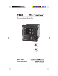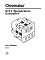
1
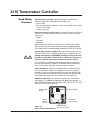
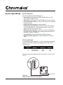
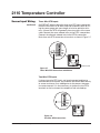
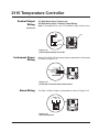
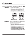
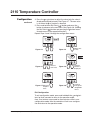
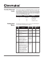
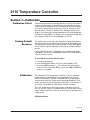
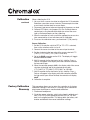
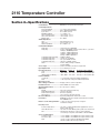
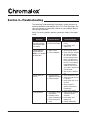
2110 Temperature
Controller
10
21
x
alo
rom
h
C
ad
m
r
Ala
p
m
Te
t
in
Po
User Manual
0037-75409
PK498-1
May, 2012
C
UL
®
US
°C
t
Se
Lo
°F
t
in
Po
Table of Contents
Manual Sections
1–Quick Setup.........................................................................................1
2–Introduction.........................................................................................2
3–Installation and Wiring.........................................................................4
4–Adjusting Setpoint and Configuration...............................................12
5–Controller and Alarm Operation.........................................................16
6–Replacing Output Modules................................................................17
7–Calibration.........................................................................................19
8–Specifications....................................................................................21
9–Troubleshooting.................................................................................22
Illustrations
1.1 Dip Switch Settings.........................................................................1
1.2 Establishing the Set Point...............................................................1
1.3 Adjusting the Set Point....................................................................1
2.1 Front Panel Identification................................................................2
2.2 Typical Application..........................................................................3
2.3 Model Identification.........................................................................3
3.1 Default Dip Switch Settings............................................................4
3.2 Removing Mounting Collars............................................................5
3.3 Mounting Dimensions.....................................................................6
3.4 Mounting the 2110..........................................................................6
3.5 Wiring Terminal Identification..........................................................7
3.6 Thermocouple Connections with Shield.........................................8
3.7 Three-Wire RTD Connections with Shield.......................................9
3.8 Two-Wire RTD Connections............................................................9
3.9 Control Output Wiring–R1 and S0.................................................10
3.10Control Output Wiring–R3.............................................................10
3.11Control Output Wiring–V0.............................................................10
3.12Control Output Wiring–S1 and S2.................................................11
3.1390-260 VAC Instrument Power Connections................................11
3.14Alarm Connections........................................................................11
4.1
4.2
4.3
4.4
4.5
4.6
4.7
4.8
Establishing the Set Point.............................................................12
Adjusting the Set Point..................................................................12
Configuring 2110...........................................................................13
Configuring 2110...........................................................................13
Configuring 2110...........................................................................13
Configuring 2110...........................................................................13
Configuring 2110...........................................................................13
Configuring 2110...........................................................................13
6.1 Replacing Output Module.............................................................18
iii
Chromalox 2110
2110 Temperature Controller
Section 1—Quick Setup
After the controller is properly wired into the system, the user
only needs to verify the sensor input and control type and adjust
the set point.
Setting the Sensor and Control Mode
Adjust the dip switches located on the bottom of the unit as
shown in Figure 1.1. The factory settings are J, TC, °F, and PI. It
is simpler to adjust the dip switch prior to mounting the 2110.
K
TC
˚F
PI
J
RTD
˚C
ONOF
J
RTD
˚C
ONOF
K
TC
˚F
PI
Figure 1.1
Dip Switch Settings
Adjusting the Set Point
1. Apply power to the unit.
2. To adjust the set point on the Chromalox 2110 Temperature Controller, press and hold the Set Point button (see Figure 1.2). The
Set Point light is illuminated.
3. While still pressing the Set Point button, press either the or
button to adjust the set point to the desired value (see Figure 1.3).
Holding the or button increases the speed of the set point
changes.
Chromalox
2110
Chromalox
Load
°F
Load
Alarm
°C
Alarm
Temp
Set Point
Point
Figure 1.2
Establishing the Set Point
2110
°F
°C
Temp
Set Point
Point
Figure 1.3
Adjusting the Set Point
The Controller is now operational with factory settings. For more
precise control, set up of the alarm, etc., see Section 4 – Adjusting Set Point and Configuration.
Section 1–Quick Setup
1
Chromalox 2110
Section 2—Introduction
Description
The Chromalox 2110 Temperature controller offers simple setup,
flexibility and control features in an attractive, compact design.
The 2110 is housed in a rugged, plastic 1/4 DIN package that
only requires four inches behind the mounting surface. Straightforward operation and easy-to-use control features are major
strengths of the 2110 controller.
Easy Three-Step Setup: The 2110 delivers exceptional process
temperature control. Your process is up and running after three
easy setup steps: 1) Select the sensor and control type, 2) Hook
up the system and 3) Select the desired temperature.
NEMA 4X Front Panel
Construction for
hosedown applications
Output LEDs
Indicates control load
ON and alarm status
Display
(4 Green, 7-Segment LEDs)
Actual process temperature displayed
Chromalox
2110
Load
°F
Alarm
Temp and Set Point LEDs
Indicates actual or set point
temperature is displayed
°C
Temp
Point
Set Point Button
• In Operation Mode, adjusts
Set Point
• In Configuration Mode with
the or button, serves
Figure 2.1
as “Menu” button
Set Point
Green LEDs
Indicates °F or °C
selected for temperature
display
• In Operation Mode,
pushbuttons adjust Set
Point.
• In Setup Mode,
pushbuttons increase/
decrease MENU values.
Front Panel Identification
Inspection and
Unpacking
Your Chromalox 2110 controller should arrive in good condition.
Upon arrival, inspect the packaging for any visible damage.
Unpack the controller and carefully inspect for product damage
that may have occurred during shipment. If the package or contents have been damaged in shipping, you must file a claim with
the delivery service. The delivery service will not accept a claim
from the shipper.
If not immediately installing the controller, store in a cool, dry
environment in its original protective packaging. Temperature
extremes and excessive moisture can damage the instrument.
Chromalox 2110
2
Section 2–Introduction
2110 Temperature Controller
Typical Application
Figure 2.2 shows the 2110 in a typical application.
Figure 2.2
Typical Application
Model
Identification
Before installation, please identify your controller model number.
The model number appears on a label on the side of the housing.
Use Figure 2.3 to identify the options in your controller.
Model
2110
1/4 DIN Controller, with Selectable Thermocouple or RTD Inputs
Code
Control Output
R1
R3
V0
S0
S1
S2
Relay, 1 Amp Form A, 120/240Vac
Relay, 20 Amps Form A, 120/240Vac
Solid State Relay Drive, 24Vdc @ 40ma
Solid State Relay, 1 Amp, up to 240 Vac
Solid State Relay, 5 Amps, up to 240Vac
Solid State Relay, 10 Amps, up to 240Vac
Code
0
1
Alarm Output (Kit Option)
No Alarm
Alarm Form “C” Relay, 5 Amps at 120Vac,
2.5 Amps at 240Vac
Code
0
Add to Complete Part Number
Code
Power Supply
0 90-260Vac
2110
-
R3
1
0
0
Typical Model Number
Figure 2.3
Model Identification
Section 2–Introduction
3
Chromalox 2110
Section 3—Installation and Wiring
Sensor and Control
Type Selection
Switches
Set the Chromalox 2110 controller’s configuration via mechanical
dip switches, located on the bottom of the unit. Factory settings are
J, TC, °F, and PI Control. Switches are easier to set before mounting.
To change the switch settings, first disconnect all wiring and power
from the unit. Adjust switch settings as follows:
SwitchFunction
A
Thermocouple
B
Input Type
C
Temperature Units
D
Control Type
SettingFactory
Options Setting
J or K
J
TC or RTD
TC
°F or °C
°F
ON-OFF or PI
PI
If input type is thermocouple, switch A selects either thermocouple
type J or K.
Switch B selects input type thermocouple or RTD (resistance temperature detector). Note: If RTD is selected, switch A is ignored.
Switch C selects temperature units °F or °C.
Switch D selects either PI (Proportional-Integral) or ON-OFF control.
J
RTD
˚C
ONOF
K
TC
˚F
PI
J
RTD
˚C
ONOF
K
TC
˚F
PI
Figure 3.1
Default Dip Switch
Settings
Chromalox 2110
4
Section 3–Installation and Wiring
2110 Temperature Controller
Mounting
Two mounting collars securely hold the 2110 controller in the
mounting hole. Remove these mounting collars before installation.
Removing Mounting Collars
1. To remove the rear collar, press the sides of the collar. This
releases holding tabs on the top and bottom of the collar.
2. Slide the collar off the back of the unit.
3. Slide the front collar off the back of the unit
Press In
Holding
Tabs
Front Collar
Rear Collar
Press In
Figure 3.2
Removing Mounting Collars
continued
Section 3–Installation and Wiring
5
Chromalox 2110
Mounting
continued
Mount the 2110
1. Cut out a 1/4 DIN, 3.6-inch (92mm) square hole in the mounting panel.
2. Insert the unit into the mounting hole as shown in Figure 3.4.
3. Slide the front mounting collar onto the back of the controller.
4. Slide the rear mounting collar onto the back of the controller
until the holding tabs securely engage with the holding tab
slots in the controller housing (see Figure 3.4).
5. Tighten the four rear collar mounting screws until the unit is
held firmly in the panel. CAUTION: Do not overtighten.
The controller will now be held firmly in place.
Chromalox
2110
Load
(92)
(12.7)
°F
Alarm
(101.6)
(10)
3.6
(92)
°C
Temp
(90)
Set Point
Point
(101.6)
(102)
(92)
Figure 3.3
Mounting Dimensions
Holding
Tabs
Slots
Holding
Tabs
Front Collar
Rear Collar
Figure 3.4
Mounting the 2110
Chromalox 2110
6
Rear Collar
Mounting Screw
Section 3–Installation and Wiring
2110 Temperature Controller
Good Wiring
Practices
Separate wire into bundles—When planning the system wiring,
separate wiring into functionally similar bundles, e.g.
• Power leads
• Sensor leads (if power leads must cross sensor leads, they should
cross at a 90° angle)
• Output signal lines
Separate sources of electrical noise—Locate all sources of electrical
noise in your system, and separate these sources from the control
system, e.g.
• Motors
• Contacts
• Solenoids
Electrical noise can affect the function of any control system. When
driving a contactor coil or other inductive load, an appropriate rated
AC snubber circuit is recommended (Chromalox Part No. 0149-01305).
Connect before power is applied—Make all electrical wiring connections to the back of the controller before power is applied to the unit.
!
Comply with regulations—WARNING: All wiring practices must comply with local regulations. Failure to do so could result in damage to
controller and/or personal injury or death from electrical shock.
This instrument is intended for panel mounting and the terminals
must be enclosed within a panel. Use National Electric Code (NEC)
Class 1 wiring for all terminals except the sensor terminals.
Check wiring decal—Check the wiring decal on the side of the unit
to verify the model number. The wiring decal shows the wiring terminations. All wiring will be connected to the terminals on the back
of the instrument case. Specific wiring instructions for different input
and output types are given in this section. See also Figure 3.5.
Additional information—For sensor wiring practices, see “Sensor
Input Wiring”. For additional information on good wiring practice, request IEEE Standard No. 518-1982 from IEEE, 345 East 47th St., New
York, NY 10017 or www.ieee.org.
Sensor Input
Wiring
Output
Wiring
(S1, S2)
Figure 3.5
Wiring Terminal Identification
Section 3–Installation and Wiring
7
Alarm Wiring
COM
NO
NC
Instrument
Power Wiring
Output Wiring
(R1, R3, V0, or S0)
Chromalox 2110
Sensor Input Wiring
Sensor Wiring Notes
For safety and best controller performance,
• Sensor leads (thermocouple and RTD) should not be run in the
same conduit as power wiring.
• Twisted pair, shielded wire is recommended for sensor connections.
• False temperature readings can occur if the sensor wire is exposed
to electrical noise.
• Ungrounded thermocouples are recommended.
• Thermocouple extension wire, if required, must be the same type
as the thermocouple (i.e. if a Type K thermocouple is used, then
Type K extension wire must be used.)
• Shielded thermocouple wire, if used, must have the shield grounded at one end only, preferably at the shield ground terminal on the
controller as shown in Figure 3.6.
• Three-wire RTDs are recommended for greatest accuracy.
• Standard shielded copper wire is recommended for RTD extensions.
Thermocouple Inputs
It is important to observe polarity (+,-) when connecting thermocouple
leadwires. ANSI color coding for the thermocouples used with this
instrument are
Thermocouple
Type
Material
Polarity (+)
Jiron/constantan white
Kchromel/alumel yellow
Polarity (-)
red
red
Make thermocouple wiring connections to terminals as shown in Figure 3.6.
TC +
TC -
NO
Figure 3.6
Thermocouple Connections with Shield
Chromalox 2110
8
COM
NC
Shield Ground
Section 3–Installation and Wiring
2110 Temperature Controller
Sensor Input Wiring
continued
Three-Wire RTD Inputs
IMPORTANT: When making the three-wire RTD input connection,
make the resistance of all three extension leadwires equal by using the same gauge and same length of wire for optimum accuracy. A three-wire RTD will generally have two wires of the same
color. Connect the same colored wires to the RTDL connections.
Connect the alternate colored wire to the RTDH connection.
Make three-wire RTD connections to terminals as shown in Figure 3.7.
RTDH
RTDL
RTDL
NO
COM
NC
Shield Ground
Figure 3.7
Three-Wire RTD Connections with Shield
Two-Wire RTD Inputs
If using a two-wire RTD input, use heavier gauge leadwires to
reduce leadwire resistance. Any leadwire resistance adds directly
to sensor resistance, thus adding error to the process temperature measurement. It is also necessary to jumper the two RTDL
terminals on the instrument to complete a two-wire hookup.
RTDH
RTDL
RTDL
NO
COM
NC
Figure 3.8
Two-Wire RTD Connections
Section 3–Installation and Wiring
9
Chromalox 2110
Control Output
Wiring
The following figures show the proper control output wiring for
the various 2110 configurations.
R1 (1 Amp Relay) and S0 (1 Amp, Solid State Relay)
Output Wiring
When driving a contactor coil or other inductive load, an appropriately rated AC snubber circuit is recommended (Chromalox
Part. No. 0149-01305), as shown in Figure 3.9.
120/240 Fuse
VAC
COM
NO
NC
Load
Neutral
Snubber
Figure 3.9
Control Output Wiring–R1 and S0
R3 (20 Amp Relay) Output Wiring
1/4” fast-on tabs are provided with the R3 output.
NO
COM
COM
NO
NC
120/240 Fuse
VAC
NO
NC
COM
Neutral
Load
Figure 3.10
Control Output Wiring–R3
V0 (Solid State Relay Drive, 24Vdc, 40mA) Output Wiring
+
120/240VAC
AC Neutral
Fuse
+
COM
NO
NC
SSR
4115 Load
Figure 3.11
Control Output Wiring–V0
Chromalox 2110
Section 3–Installation and Wiring
2110 Temperature Controller
Control Output
Wiring
continued
S1 (Solid State Relay, 5 Amps) and
S2 (Solid State Relay, 10 Amps) Output Wiring
Note: 2110 model S2 has a fan. 2110 model S1 does not have a fan.
Fan
COM
Fuse
Load
NO
NC
120/240
VAC
Neutral
Figure 3.12
Control Output Wiring–S1 and S2
Instrument Power
Wiring
Make 120 or 240 VAC instrument power connections to terminals
as shown in Figure 3.13.
120/240VAC
Neutral
Ground
NO
COM
NC
Figure 3.13
90-260 VAC Instrument Power Connections
Alarm Wiring
The Form C Relay Output is connected as shown in Figure 3.14.
C
Alarm Out
NO NC
COM
COM
NO
NO
NC
NC
Figure 3.14
Alarm Connections
Section 3–Installation and Wiring
11
Chromalox 2110
Section 4—Adjusting Set Point and Configuration
Adjusting the
Set Point
1. Set selection switches (see Figure 3.1).
2. Apply power to the unit.
3. To adjust the set point on the Chromalox 2110 Temperature Controller, press and hold the Set Point button (see Figure 4.1). The
Set Point light is illuminated and the set point value is displayed.
4. While still pressing the Set Point button, press either the or
button to adjust the set point to the desired value (see Figure 4.2).
5. Release the Set Point button.
Chromalox
2110
°F
Load
Alarm
°C
Alarm
Temp
Set Point
Point
Figure 4.1
Establishing the Set Point
Configuration
Chromalox 2110
Chromalox
Load
2110
°F
°C
Temp
Set Point
Point
Figure 4.2
Adjusting the Set Point
While the 2110 default settings make it a simple setup controller
for most applications, additional programmable menus can be
configured through three front-panel pushbuttons.
To access the user configuration menus,
1. Press and hold the and buttons. After three seconds the
display will begin to toggle between the current security code
and LocH (LOCK). The Temp and Set Point LEDs will turn on.
See Figure 4.3.
2. Press the or button to adjust the value to the appropriate
security number (see Security Codes and Levels). Only the
value is displayed during adjustment. See Figure 4.4.
3. Press and hold the Set Point (
) button and press the or
buttons to scroll the configuration menus. The display will
show the name of the menu and then begin to toggle between
the name and the current value. See Figures 4.5 and 4.6.
12
Section 4–Adjusting Set Point and Configuration
2110 Temperature Controller
Configuration
continued
4. Press the or buttons to adjust the value (only the value is
displayed during adjustment). See Figure 4.7. The new value
is set when the or button is released.
5. Press and hold the Set Point (
) button and press the
button to advance to the next menu. See Figure 4.8. (Holding
the Set Pointt (
) button and pressing the button moves
through menus in the opposite direction.)
Repeat steps 4 and 5 through the configuration menus.
Chromalox
2110
Chromalox
Load
˚F
Load
Alarm
˚C
Alarm
Temp
˚F
˚C
Set Point
Temp
Set
Point
2110
Set Point
Set
Point
Figure 4.3
Adjust lock
to 458
Figure 4.4
Chromalox
Chromalox
2110
Load
˚F
Load
Alarm
˚C
Alarm
Temp
˚F
˚C
Temp
Set Point
2110
Set Point
Set
Point
Set
Point
Move to
next menu
Figure 4.5
Chromalox
Continue
until SP is
displayed
Figure 4.6
Chromalox
2110
Load
°F
Load
Alarm
°C
Alarm
Temp
˚F
˚C
Temp
Set Point
2110
Set Point
Set
Point
Point
Figure 4.7 Adjust the
set point
value
Figure 4.8
Continue
through the
configuration
menus
Exit Configuration
To exit configuration mode, press and hold both the and
tons for three seconds to return to the operation mode.
but-
Note: If no buttons are pressed for three minutes while in user
configuration mode, then the controller will exit user configuration and return to the operation mode.
Section 4–Adjusting Set Point and Configuration
13
Chromalox 2110
Security Codes and
Levels
To limit access to the user configuration interface, security codes
are assigned to different menu levels. Make security codes available to operators, maintenance crew, supervisors, etc. according
to what function level you want for each group. Security Level C
is not recommended for most users. Gain access to configuration menus using the following codes.
Security Level
Configuration
Menus
Function
A
All Values
Allows adjustment of
the Set Point
B
458
Basic menus
C
736
Calibration menus
The following configuration menus can be accessed through the
user interface (see Configuration, page 12).
Menu
Code
Chromalox 2110
Security Code
Adjustable Factory
Range
Default
Function
Loch
Security Lock
Proc
Security
Level
0-999
458
A
Process Variable Display
Read Only
°F or °C
N/A
A
SP
Process Set Point Adjust
Sensor
Range
°F or °C
0°F
A
Pb
Proportional Band
1 to Sensor
Span
Maximum
°F or °C
25
B
ArSt
Automatic Reset
0.0 to 100.0
Repeats/
Min.
0.1
Displays the actual process
temperature.
Adjusts the target process
temperature.
Temperature range above/below
set point where proportional
control is active. Most
applications require a band
between 10 to 200°F. This menu
is active only when the dip
switch is set to “PI”
Control feature that
automatically corrects for small
temperature offsets that occur
in proportional control. The
higher the setting, the faster the
correction occurs. A high setting
could cause overshoot during
start-up. A low setting will not
allow process temperature
to reach to set point quickly
enough. A setting of “0” turns
off automatic reset. This menu
is active only when the dip
switch is set to “PI”.
14
Section 4–Adjusting Set Point and Configuration
2110 Temperature Controller
Configuration
Menus
continued
Menu
Code
Function
CYCL
Cycle Time
db
Adjustable Factory
Range
Default
Security
Level
.1 to 60.0
Sec.
Output
R1, R3 =
30 sec.
S0, S1,
S2, V0 =
1 sec.
B
On/Off Dead Band
1 to 100 °F
or °C
5 Foc
B
ALty
Alarm Type
Off, Hi or Lo
OFF
B
ALSP
Alarm Set Point
0 to 100 °F
or °C
5
B
ALdb
Alarm Dead Band
0 to 100 °F
or °C
5
B
SPLL
Set Point Lower Limit
Sensor
Range
°F or °C
Span
Low
B
SPUL
Set Point Upper Limit
Sensor
Range
°F or °C
Span
High
B
outl
Output Limit
0 to 100%
100
B
The time for the output to
complete ON to OFF to
ON cycle. Used only with
proportional control. A fast
cycle time provides better
control, but can cause
premature wear to contactor or
other power switching devices.
Magnetic contactors should not
be switched at less than a 30
second cycle time. This menu
is active when the dip switch is
set to “PI”.
The range above/below set
point in which no control action
takes place. Determines at
what temperature the output
switches ON and OFF. For a 5°F
dead band, 2.5°F is above and
below the set point. This menu
is active when the dip switch is
set to “ONOF”.
Select high or low alarm.
Temperature level that will
actuate the alarm.
Difference of temperature from
alarm set point before an active
alarm resets.
Lower limit to which set point
may be set without security
code access.
Upper limit to which set point
may be set without security
code access. This prevents
an operator from setting the
set point temperature to a
level which would damage
equipment or process.
Limits the percentage of
output that can be applied in
proportional control.
For calibration menus (CoFF, dFLt, & CALS), see Section 7–
Calibration
Section 4–Adjusting Set Point and Configuration
15
Chromalox 2110
Section 5—Control and Alarm Operation
Control Operation
The 2110 is shipped from the factory with PI (proportional/integral) control. Proportional control actually determines the percent of heat needed
to control the process. The factory setting for the Proportional Band is
25°F and the Automatic Reset (Integral) is set at 0.1 repeats/minute.
These settings will control many processes without any changes to the
controller. If the process is unstable or too sluggish, the Proportional
Band and Automatic Reset can be changed in the menu configuration.
Tuning PI Control
Adjust Proportional Band The objective of the proportional band adjustment is to find the proportional band setting at which the process
temperature stabilizes and does not oscillate. If the temperature display
is oscillating, increase the Proportional Band (doubling the value) until
the temperature display has stopped oscillating. To establish a quick
response to control upsets, adjust for the smallest band that provides
stable control (does not oscillate). Note: The temperature at this point
may not be at set point, but will be stable.
Adjust Automatic Reset (Integral) The Automatic Reset (Integral) automatically removes the offset between process temperature and set
point. If the process is too sluggish in approaching set point, double the
automatic reset. Too much automatic reset will make a process unstable.
Cycle Time Cycle time setting determines how often to switch the
output to the heater. For example, if the cycle time is 1 second and the
2110 needs a 75% output, the output will be on for 3/4 of a second
and off 1/4 of a second. Units with relay control outputs (R1 or R3) are
shipped with a 30-second cycle time. Units with solid state relays or
solid state relay drives (S0, S1, S2, or V0) are shipped with a 1-second
cycle time.
Alarm Operation
(optional)
Chromalox 2110
An alarm relay output is optional on the 2110. An alarm can help protect
the process when a too high or too low temperature occurs.
High Alarm: This alarm is a high absolute alarm that actuates when the
process temperature is equal to or greater than the alarm set point. For
example, if the high alarm set point is 500°F, the alarm will always actuate when the process temperature reaches 500°F.
Low Alarm: The low absolute alarm actuates when the process temperature is equal to or less than the alarm set point. The low alarm features a
power-up inhibit to prevent undesirable alarms during process start up.
After the unit reaches control set point, the low alarm will respond.
Alarm Dead Band: The alarm relay de-energizes (resets) when the temperature crosses out of the alarm dead band. For example, if the high
alarm is set to 500°F and the alarm dead band is 5°F, the alarm condition
will not reset until the process temperature reaches 495°F.
To enable the alarm relay, select either high or low alarm type and set the
alarm set point. An alarm condition is indicated when the Alarm light to
the left of the display illuminates. Alarm type, set point, and dead band
are selectable through the user configuration interface.
16
Section 5–Control and Alarm Operation
2110 Temperature Controller
Section 6—Replacing Output Modules
The Chromalox 2110 Temperature Controller was shipped with the
output modules installed as ordered. The 10A Solid State Relay and
20A Mechanical Relay output cards control small cartridge heater or
strip heater loads directly, eliminating the need for a remote contactor or solid state relay. If a larger load is required, the 2110 can be
configured with a 1A Pilot Duty Relay or Solid State Relay Drive.
The 2110 may be optionally configured with a 5A/120V Alarm Relay.
Alternate modules, configured with or without alarm, can be installed
as needs change.
Control and alarm outputs can be changed in the field.
Module Option
Descriptions
Output Module options are as follows
Load/Sourcing
Description
Specification
R1 Relay
Form A contact, SPST,
N.O. 1.0 Amp at 120/240
VAC resistive load
R3 Relay
Form A contact, SPST,
N.O. 20 Amp at 240
VAC, 28 VDC resistive
load
V0 SSR
24 VDC nominal at 40
Drive
mA
S1 TRIAC
1 amp continuous, 10
Amp in-rush 120/240
VAC
S1 Solid
120/240 VAC, 5 Amp @
State Power 40°C ambient
Controller
S2 Solid
120/240 VAC, 10 Amp @
State Power 40°C ambient with builtController
in cooling fan mounted
on rear of housing
Module Installation
!
Factory
Default
Cycle
Time
30 sec.
Part No
w/o Alarm
0149-27133
Part No. w/
Alarm
0149-27147
30 sec.
0149-27132
0149-27146
1 sec.
0149-27135
0149-27149
1 sec.
0149-27134
0149-27148
1 sec.
0149-27136
0149-27150
1 sec.
0149-00022
(Fan Kit)
0149-00022
(Fan Kit)
WARNING: Remove power from the controller before changing the
output module. Failure to do so could cause damage to controller
and/or personal injury or death from electrical shock.
When handling output modules, be careful to guard the module
against static discharge. Follow the steps below to remove an existing output module and replace it with a new module.
Removal
1. Remove power from the controller.
2. Remove all terminal connections.
Section 6–Replacing Output Modules
17
continued
Chromalox 2110
Module Installation
continued
!
3. Remove the back cover by lifting four housing clips on the controller. This releases the back cover. Then pull cover straight off
the controller.
4. Gently pry around the sides to loosen and remove the module.
Pull module straight out to avoid bending pin connections.
WARNING: Do not remove module by the handling components on
the module board. This could damage the module.
When removing an S2 output module (SSR with fan), a cable connects the fan to the far right center of the S2 board. Gently disconnect the cable from the connector on the output board. Do not
remove the fan from the back cover. This is a single assembly.
For the S2 output module, reconnect the fan cable to the connector on the far right center of the module. Tuck the cable around
the heatsink.
Replacement
1. Line up pins on the controller with pin connections on either side
of the module and push the new module into place.
2. Reinstall the back cover.
Controller
Pin
Module
Housing
Clip
Back Cover
Figure 6.1
Replacing Output Module
Auto Cycle Time
The Control Output Modules have a default cycle time of 1 second
(fast switching) or 30 seconds (slow switching) (See table on page
17). After replacing a control output, the 2110 verifies at power up
if a slow or fast cycle time output has been installed. If an output
with a different default cycle time is installed, the 2110 will change
the cycle time to the new device’s default. If the user has changed
the cycle time in configuration, the 2110 retains this value unless
an output with a different default cycle time has been installed.
Chromalox 2110
18
Section 6–Replacing Output Modules
2110 Temperature Controller
Section 7—Calibration
Calibration Offset
Calibration offset offsets the displayed value. Usually, this option is
used to match displays of two different instruments that are measuring the same temperature, but are displaying different temperatures due to different thermocouple accuracy or placement of the
thermocouples. Caution is advised when adding an offset to the
display, since the actual sensed temperature will not be displayed.
Calibration offset (coFF) is available in the configuration mode, but
only displays if the security lock (LocH) is set to 736.
Factory Default
Recovery
This option allow you to return the controller’s configuration parameters back to the factory default values (except for the LocH menu).
This parameter could be used when moving a unit from one application to another to give the operator an easy place to begin setup of
the unit.
Factory Default Recovery is performed in the Configuration Mode,
menu dFLt. The security lock (LocH) must be set to 736 to perform
a factory default recovery.
To reestablish the factory default values:
1. Disconnect load power.
2. In the Configuration Mode, set security level (LocH) to 736.
3. Go to menu dFLt and press . The controller will automatically
reset the values. When the display cycles from rEdy to donE, the
recovery is complete.
Calibration
The Chromalox 2110 Temperature Controller is factory calibrated
before shipment. Recalibration is not needed when you receive
and install the product. Periodic calibration checks or adjustments
should not be necessary under normal operating conditions. Chromalox recommends you recalibrate the controller if all instruments in
your facility are periodically calibrated to a known standard.
The 2110 always retains the original factory calibration values for
the J, K, and RTD inputs. In an application, only one of these sensor
inputs will be used. The 2110 only can retain manual calibration for a
single sensor.
Calibration Notes:
continued
Section 7–Calibration
19
Chromalox 2110
Calibration
continued
When calibrating the 2110
1. You must have a sensor simulator to calibrate the 2110 controller.
Substitute a precision sensor simulator (Thermocouple simulator
or resistance simulator box) for sensor inputs.
2. Disconnect load power to prevent damage to the process or load.
3. Calibrate RTD inputs using copper (Cu) wire. Calibrate thermocouple inputs using thermocouple extension wire of the same
type as the thermocouple you are calibrating.
4. Allow the controller to warm up with the appropriate sensor simulator connected for at least one hour prior to calibration.
5. To access the calibration menu, you need level C (736) security.
Sensor Calibration:
1. Set the 2110 selection switch to RTD or TC. If TC is selected,
then set the selection switch to J or K.
2. Connect the sensor simulator to the sensor input terminals.
3. Set the simulator to the low value of the sensor selected J TC
(-100°F), K TC (-100°F), RTD (-200°F or 48.46W).
4. Go to the CALS parameter on the 2110. The display will toggle
between CALS and inLo.
5. Wait 30 seconds for the electronics to fully stabilize. Press .
Dashes will appear in the display while the controller calibrates
the low end of span.
6. When the controller prompts inHi in the display, adjust the sensor
simulator to the high end of the selected sensor span.
J TC (1400°F), K TC (2400°F), RTD (1000°F or 293.49W).
7. Wait 30 seconds for the electronics to fully stabilize. Press .
Dashes will appear in the display while the controller calibrates
the high end of span. When finished, the controller will display
donE.
8. Calibration is complete.
Factory Calibration
Recovery
Chromalox 2110
This procedure allows you to return the controller to its factory
calibration settings in the event it is severely out of calibration
due to poor technique or unauthorized calibration.
1. Disconnect load power.
2. Cycle the sensor selection switch twice from its original position (TC or RTD) to the opposite position (RTD or TC) and
back to its original position. This brings back the factory calibration and deletes the manual calibration settings.
20
Section 7–Calibration
2110 Temperature Controller
Section 8—Specifications
Control Modes ................................. ON/OFF; PI—Proportional with integral
Control Adjustments
Proportional Band...................... 1 to sensor span maximum
Automatic Reset......................... 0.0 to 100.0 repeats/minute
Cycle Time................................. 0.1 to 60.0 seconds
On/Off Deadband....................... 1° to 100°F or °C
Set Point Upper Limit................. sensor range °F or °C
Set Point Lower Limit................. sensor range °F or °C
Output Limit............................... 0 to 100%
Alarm Adjustments
Type............................................ Absolute High or Low
Set Point..................................... Sensor range °F or °C
Alarm Dead Band....................... 0° to 100°F or °C
Control/Alarm Outputs
Relay (R1)................................... 1 Amp Form A, 120/240VAC
Relay (R3)................................... Form A, 120/240VAC resistive loads at 30 sec. cycle time
20 Amps, 500,000 Operations
15 Amps, 1 Million Operations
10 Amps, 5 Million Operations
5 Amps, 5 Million Operations
Solid State Relay Drive (V0)........ 24VDC at 40mA
Solid State Relay (S0)................. 1A Triac, up to 240VAC
Solid State Relay (S1)................. 5A, up to 240VAC at 40°C
Solid State Relay (S2)................. 10A, up to 240VAC at 40°C
Alarm.......................................... Form C, Relay 5 Amps at 120VAC,
2.5A at 240VAC
Sensor Input ..................................... Switch selectable; J,K Thermocouple; RTD
Input Update Rate ........................... Four samples per second
Input Specifications ........................ Range °F
Range °C Accuracy at 77°F ambient
J TC............................................ -100 to 1400°F -73 to 760°C 0.2% Span +/-1 least significant digit
K TC........................................... -100 to 2400°F -73 to 1316°C 0.2% Span +/-1 least significant digit
100W Pt RTD (a=.00385)............ -200 to 1000°F -128 to 538°C 0.2% Span +/-1 least significant digit
Readout Stability
J and K TC................................. +/-1°F per 10°F change in ambient temperature
RTD............................................ +/-0.5°F per 10°F change in ambient temperature
Open Sensor and
Out-of-Range Conditions ............... Displays “SEnS”, Control output 0%
Instrument Power ............................ 90 to 260VAC Less than 10 VA
Operating Environment ................... 0° to 65°C (32° to 150°F)
Dimensions
Overall........................................ 4.0 x 4.0 x 4.0 inches (102 mm)
Depth Behind Display................. 3.6 inches (92 mm)
Front Panel Projection................ 0.4 inches (10 mm)
Panel Cutout.............................. 3.6 x 3.6 inches (92 mm x 92 mm)
Enclosure Material .......................... High temp ABS plastic rated for 0° to 175°F
Front Panel NEMA 4X construction, requires surface finish not rougher than 0.000032 inch
Influence of Line Voltage Variation ... +/-0.1% of sensor span per 10% change in
nominal line voltage
Noise Rejection
Common Mode Noise................ Less than 2°F with 240 VAC, 60 Hz applied from sensor
input to earth ground
Series Mode Noise..................... Less than 2°F with 100mV, peak to peak series mode noise
RFI.............................................. Typically less than 0.5% of sensor span at distance
of 1 meter (3.1 feet) from a transmitter of 4W at 464MHz
Sensor Leadwire Effect
J Thermocouple......................... +1°F for 1000 ft. of 18 AWG thermocouple extension wire
K Thermocouple......................... +2°F for 1000 ft. of 18 AWG thermocouple extension wire
RTD
+/-0.1% of sensor span per 20W balanced leadwire
resistance (20W is the total loop resistance)
Section 8–Specifications
21
Chromalox 2110
Section 9—Troubleshooting
The following Troubleshooting Guide offers simple solutions to
common problems and explains the 2110’s Error Messages. Review this section for a possible solution to your problem before
contacting Chromalox.
Note: For each symptom, perform correction steps in the order
listed.
Symptom
Power applied, display does not light,
and controller does
not function
Probable Cause
Correction Steps
1. No power applied 1. Check power wiring and
fusing
2. External fuse open
2. Power down and
repower up
Display alternates
1. Open sensor
between HI and
2. Out of calibration
SENS, 2110 disables
control output
Process does not
heat up
Erratic operation
Chromalox 2110
22
1. Check sensor wiring
2. Check selection switches
3. To verify that controller is at fault, remove
the thermocouple and
place a jumper across
the sensor terminals of
the 2110. If the display
reads approximately
ambient, then the sensor is open. Replace the
thermocouple.
4.See Section 7–Calibration
1. No power being
1. Verify Load LED is ON
applied to the load 2. Verify the heater or fuse
2. Load fuse open
is not open
3. Verify output limit is set
to 100%
4. Verify set point is
greater than process
temperature
5. Verify output wiring
1. Intermittent sensor 1. Check sensor wiring or
connections
substitute sensor
simulator
2. Controller failure
(internal electronics) 2. Power down and
repower up
3. External electrical
noise
3. Contact Chromalox
Section 9–Troubleshooting
2110 Temperature Controller
Troubleshooting
continued
Symptom
Process not in
control
Probable Cause
1. Incorrect settings
2.Thermocouple
Wiring
Instrument continu- 1. Severe electrical
ally goes through
noise
power-up reset
Section 9–Troubleshooting
23
Correction Steps
1. Check Proportional
Band setting and Automatic Reset setting
2. Check thermocouple
polarity
1. Separate sensor wiring
from other wiring
2. Apply power line filter
3. Contact Chromalox
Chromalox 2110
Limited Warranty:
Please refer to the Chromalox limited warranty applicable to this product at
http://www.chromalox.com/customer-service/policies/termsofsale.aspx.
1347 HEIL QUAKER BLVD., LAVERGNE, TN 37086
Phone: (615) 793-3900
www.chromalox.com