1
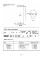
ARTESIAN 220 & 340
Instantaneous Indirect Water Heater
By Dunkirk Boilers
• INSTALLATION AND
OPERATING INSTRUCTIONS
• ENGINEERING MANUAL
Manufacturer's Warning
To reduce the possibility of injury due to scalding, a thermostatic mixing
valve should be installed on all installations. Failure to do so will result
in domestic water being delivered to the faucets at a temperature
equivalent to the boiler water.
All commercial installations requiring sustained water temperatures
beyond 120°F, must label all fixtures alerting water users of a potential
scalding hazard.
Page 2
CONTENTS
pg
I. Product Description................................................................................................ 4
II. Specifications ......................................................................................................... 4
III. Sizing A Water Heater For Installation................................................................ 7
Method A - Quick Residential............................................................................. 8
Method B - Detailed Residential........................................................................ g
Method C - Commercial....................................................................................13
IV. Before Starting Installation ................................................................................19
V. Locating the Water heater..................................................................................19
VI. Piping ..................................................................................................................20
Zone Design
Boiler Side Piping .............................................................................................21
Domestic Piping ................................................................................................29
VII. Wiring..................................................................................................................33
VIII. Start-up and Check-out....................................................................................40
Appendix A ......................................................................................................... 40
Page 3
I. Product Description
The Indirect water heater is designed to generate domestic hot water in conjunction with a hot water
boiler using forced boiler water circulation. This indirect water heater consists of a plain steel tank in
which three smooth copper coils are located. The tank surrounded by 2" of Poly - urethane foam
insulation, which is surrounded by an enamel coated plain steel jacket.
The boiler water pumps through the tank and heats the domestic water in the coils.
Specifications
Page 4
Page 5
Page 6
Ill.
Sizing The Hot Water Heater For Installation
IMPORTANT
The following procedures are used to size indirect water heaters based on the amount of
hot water required during a given hour. In doing so, it is assumed that this demand will be
spread out over the course of the entire hour.
THESE SIZING PROCEDURES ARE PROVIDED AS A GUIDE TO ASSIST THE PROFESSIONAL
CONTRACTOR IN SIZING THE WATER HEATER. BECAUSE OF THE LARGE VARIETY OF
DEMAND SITUATIONS ENCOUNTERED IN THE FIELD, THE MANUFACTURER CANNOT
GUARANTEE THE SUITABILITY OF THESE PROCEDURES TO ALL INSTALLATIONS.
To properly apply the water heater to a particular system, the following 3 steps must be done:
1) Determine the domestic hot water requirements
2) Select the correct water heater/ boiler combination
3) Select a pump, zone piping size, and control system to provide proper water flow from
the boiler through the water heater tank.
This manual presents three methods of sizing this water heater:
Method A: Quick Residential
Method B: Detailed Residential
Method C: Commercial
Note:
The terms gross output and heating capacity are used interchangeably in this manual. Heating
Capacity is the gross output of boilers of less than 300,000 Btu/Hr input as defined by D.O.E. test
procedures. Gross Output is the term generally used with boilers of greater than or equal to
300,000 Btu/Hr. input.
Page 7
Method A: Quick Residential Sizing Method
Table 4 shows some typical structures under which many single residence applications can be
classified. This procedure will provide satisfactory results most of the time. Where greater accuracy
is desired, use Method B.
1) Find the description that best fits the job and select the Water heater called for. Also, note the
required boiler output under column (F).
2) The Water heater must be installed with a boiler having a gross output (DOE heating capacity)
greater than or equal to that shown in column (F) of Table 4. If the Water heater is to be used with
a boiler having a gross output less than that shown in table 4, use Method B.
If a boiler is to be installed with a water heater, first find a boiler, which will handle the spaceheating load alone. If this boiler has a DOE heating Capacity greater than that shown in column
(F) of table 4, do not add anything to the boiler selected for the Artesian.
If the boiler required for space heating alone has a DOE heating capacity less than that called
for in column (F) of table 4, increase the size of the boiler selected to one with a DOE heating
capacity greater than or equal to that show in column (F).
3) See figures 5-7 for more information on designing a water heater zone system. It is recommended
that the zone be given priority.
Page 8
Method B Detailed Residential Sizing Method Directions
1) Record the total number of each type to fixture in column (c) of worksheet 1. A shower head is
installed over a bathtub, count both the bathtub and shower head although only one fixture will
be used at a time.
2) For each line, multiply the quantity entered in column (c) by the corresponding number in column
(b). Enter the result in column (d).
3) Total column (d). This is the PEAK HOUR DEMAND
4) Multiply the Peak Hour Demand by 1.20. This is the adjusted peak hour demand
5) Select the water heater based on:
a) If a new boiler is to be installed with the Artesian:
* Go to table 1 and select a water heater which has a 140°F first hour rating greater than or
equal to the adjusted peak hour demand calculated on work sheet 1.
* Refer to required boiler output in Table 1. Record the required boiler output (heating
capacity) for the selected water heater in your work sheet.
* Determine the boiler required to satisfy the space heating requirement alone by
multiplying the space heating load by 1.15. Record this, as the boiler heating capacity
required for space heating in your work sheet.
* Select the boiler with the larger of the above two heating capacities.
b) If the water heater is to be installed with an existing boiler:
* Go to table 1 and select a water heater which has a 140°F first hour rating greater than or
equal to the adjusted peak hour demand calculated above.
If the required boiler output for the selected water heater is greater than the heating
capacity of the existing boiler; the existing boiler is too small.
6) If a Whirlpool is on the job, see Appendix A.
7) Designing the water heater zone system. Refer to Table 1 for minimum boiler water flow, and
circulator sizing. For further information on zone systems refer to figures 4-9.
Page 9
Page 10
Method B - Detailed Residential Sizing Sample Calculations
Example 1
A water heater is to be installed with a new boiler. The residence has the following fixtures: Bath
#1
Bath #2
3 GPM Shower Head
Vanity
30 Gal. Bathtub
Vanity
Kitchen
Laundry
Kitchen Sink
Clothes Washer
Automatic Dishwasher
The heat loss of the house is 80,000 BTU/hr
Note:
Although a four section boiler would be capable of heating the house (Net Rating = 82,000 BTU/hr),
its DOE heating capacity is only 94,000 BTU/hr (Need 110,000 Btu/hr). For this reason, install a
five section boiler that has a heating capacity of 125,000 BTU/hr.
Solution:
The completed sizing sheet for this example is shown in figure 2. The adjusted peak hour demand
is 145 gallons per hour. From table 1, we see that a water heater 220 will fulfill this requirement
with the appropriate boiler. Refer to Table 1 for required boiler output. If the model 220 is used in
combination with a boiler capable of producing 110,000 Btu / hr. The output will give you 156 GPH
first hour ratings. The circulator on the boiler must be capable of producing 3.4 GPM.
Page 11
Page 12
IMPORTANT
Do not attempt to use Method C to size a single-family
residence.
Method C: Commercial Sizing Method Directions
1) Table 5 and 6 show demands for various fixtures found in commercial buildings in
gallons per hour. To determine the hot water requirements of the building:
a)
Using Worksheet 2, determine and record the total number of each type of fixture in
the building under Column (2)
b) Use Tables 5 and 6 to find the number of gallons of 140°F water used per hour per
fixture. Record this value for each fixture in Column (1).
c)
Multiply each line in Column (1) by the number in Column (2). The result is the total
amount of water used for each type of fixture type per hour. Record this in Column
(3).
d) Total Column (3). The result is the total amount of water used by all fixtures per
hour. This is the possible maximum demand.
e) The demand factor is intended to take into consideration the fact that not all
fixtures will be in use at the same time. Use the appropriate demand factor from
Table 5. Multiply the total demand calculated in step (d) by this factor. The result is
the probable maximum demand.
f)
If a commercial dishwasher or laundry is on the job, determine the maximum amount
of 140°F water, which could be used in an hour. This will depend upon the number
of machines, the amount of water used per machine and the way in which the
equipment is to be used. Consult the machine manufacturer and the building owner
for this information. Once the maximum hourly usage is known for this equipment,
enter it in the spaces provided under Column (3).
g) Add the hourly usage for dishwashers and washing machines to the Probable
Maximum Demand. This is the Adjusted Probable Maximum Demand. Select the
water heater
2)
a)
If a new boiler is to be installed with the water heater, go to Table 1 and select a
water heater which has a 140°F first hour rating greater than or equal to the
Adjusted Probable Maximum Demand calculated in Method C step 1 g.
Determine the boiler size required to satisfy the space-heating requirement alone.
Note the gross output or Heating Capacity of this boiler. Compare the boiler's gross
output
required for the water heater and the gross output required for the space heating
(Gross output required for space heating = heating load x 1.15). Use the boiler
sized to the larger amount.
Page 13
b) If the water heater is to be installed with an existing boiler, go to table 1 and select a
water heater which has a 140°F first hour rating greater than or equal to the adjusted
probable maximum demand calculated in1g. Note the boiler's gross output required to
achieve the selected water heater's first hour ratings. If it is more than the gross output
of the existing boiler, the existing boiler is too small to provide the proper input to the
water heater.
3) Several water heaters may be used together to provide a greater first hour rating than the
largest available single Artesian, if needed. If this is done, keep the following in mind:
* The first hour ratings of several Artesians may be added together to give a first hour
rating for the total system.
* The gross boiler output required for each individual water heater must be totaled to
provide the gross boiler output required for the system.
* Use water heaters of equal size. Do not mix tanks of different sizes on the same
manifold.
* See the "Piping" and "Wiring" sections of this manual for proper installation of a
manifold system.
4) Note: Use of a storage tank can increase the system's performance by providing a buffer for
periods of high demand.
5) Keep in mind the following before settling on the choice made above:
Many building's peak demands result from the constant use of one type of fixture or
machine for a relatively short period of time (showers in a gymnasium, for example).
The procedure outlined above may not provide adequate hot water in these cases. The
best way to size water heaters for this type of application, is to determine the total flow
rate of all fixtures. Which are, or could be, in use at once and select a water heater from
Table 1, which will provide hot water at this flow rate for the period of time required.
Page 14
Page 15
Method C - Commercial Sizing Sample Calculation Example 2
This application is for a motel with 20 rooms. Each of these rooms has the following
fixtures: (1) Vanity, (1) Shower and (1) Bath
In addition, 5 rooms have an additional vanity. Also, there is a utility sink used by the staff
for cleaning and a laundry with two machines
Solution:
Use Table 5 and the fixture count to complete the example worksheet in figure 3 (on next
page). Note that we treated the vanities as "Private Lavatory Basins" and the utility tub as a
"Laundry Tub". From discussions with the washing machine manufacturer and the motel
owner, we find that 100 Gal/hr of 140°F water is used in the Laundry. This usage is recorded
on the "Laundry Line" at the bottom of Worksheet 2. The demand factor of 0.25 for a hotel is
from Table 6. The Probable Maximum Demand is 0.25 x 1978 = 494.5 GaVhr. To this, we add
the 100 GaVhr laundry usage for an Adjusted Probable maximum Demand of 594.5 Gal/hr.
From table 1, Select the most cost-effective combination of equal size Artesians that will
satisfy this requirement. In this case 2 model 340's, with 305 gph first hour rating at 140°F,
are selected. Combined first hour rating is 610 gph (2 x 305). The total gross boiler output
required is equal to the requirement for each model multiplied by the total number of water
heaters. In this case 2 x 220 = 440 MBH gross boiler output is required. Likewise, their total
boiler water flow through the water heater zone is equal to the requirement for each water
heater times the total number of water heaters. In this case (2 x 6.7) = 13.4 gal / min.
Page 16
Page 17
Page 18
IV. BEFORE STARTING INSTALLATION
Table 7: Water Chemistry Requirements
1) Make sure that the planned installation is
Water used in the water heater must have
in accordance with all local codes.
characteristics falling within the following limits:
2) Be certain the domestic water supply to the tank
Characteristic
Min.
Max.
fall within the limits shown in Table 7. Where
pH
6.0
8.0
questions exist as to the composition of the
Dissolved Chlorine (PPM)
0.0
100.0
water on the job, a qualified water treatment
No measurable amounts of chlorine containing
expert should be consulted.
compounds, such as cuprous chloride, are permitted.
has physical and chemical characteristics that
IMPORTANT
Water with characteristics outside the limits shown in Table 7 may severely shorten the life of the heat
exchanger due to corrosion. Damage to the heat exchanger is not covered under warranty. Do not use the
water heater if the water is excessively hard. Lime and other deposits will occur and reduce the unit's
effectiveness.
3)
Read and understand all installation requirements in this manual.
4) When adding a water heater to an existing system, the additional water content of the tank must be
considered. Verify that the expansion tank sizing is correct.
IV Locating The Artesian
WARNING
Failure to properly support a water heater tank installation could result in property damage or personal injury.
1) Table 2 shows the weights of all water heaters filled with water. The location chosen for the water heater
must be capable of supporting both the weight of the water heater(s) and the weight of the boiler(s).
2) Locate the water heater in an area where a leak in the tank, or the adjacent piping, or an open temperature
and pressure relief valve will not damage the surrounding `structure. If the area around the desired tank
location is highly susceptible to water damage, install the water heater in a pan with a drain.
3) The water heater may be located some distance from the boiler provided the piping system is designed to
provide the minimum boiler water flow called for in Table 1. Also, the further the water heater is from the
boiler, the longer the response time of the boiler will be to a call for heat from the water heater zone. If long
runs exist between the boiler and the water heater, it is advisable to insulate the piping.
Page 19
V. Piping
IMPORTANT
All First Hour Ratings shown in this manual are based on the, minimum boiler water, flow rates shown in
Table 1. Read this section for information on sizing piping and circulators for the water heater zone. Zone
Design
In designing the water heater zone piping system, the following points should be considered: 1) Circulator or
Zone Valve Zoning? - Circulator zones are usually a better choice. Zone valves have a relatively high
pressure, drop with respect to flow rate required through the water heater tank (see Table 1).
If zone valves are selected, use a zone valve with a minimal delay in opening, such as a motorized type.
a) Priority Zoning - Priority zoning is used to divert all boiler output to the water heater when its zone calls for
heat regardless of any simultaneous calls for heat from space heating zones
b) Priority zoning can be done using a 3-way zone valve, or by using a relay to de-energize the heating
zones when the water heater calls for heat. (See the piping and wiring sections for more information on these
zone systems).
Boiler Side Piping
Figures 4-9 show typical boiler side piping for several common situations. Regardless of which system is
used, it is imperative that the minimum boiler water flow rates called for in Table 1 are developed through
the tank. This requires properly sized piping and a properly sized pump. The systems shown in figures 49 are described below:
Standard Circulator Zone
This system is just like the circulator zone system on a straight heat job except that one of the zones goes
to the water heater tank instead of radiation. As on any circulator zone system, appropriate controls should
be installed in each zone to prevent unwanted circulation through zones, which are not calling for heat.
Figure 4 illustrates typical circulator zone piping.
Zone Valve System
As with the circulator zone system, this system is just like a standard heating only zone valve system
except that one of the zones is connected to the tank. The circulator must be large enough to move the
boiler water through the tank at the minimum boiler water flow rate called for in Table 1, regardless of the
flow rate required through the heating zones. Figure 5 illustrates a typical zone valve system.
Page 20
3-Way Zone Valve System
This system offers a simple method of prioritizing the tank (Diverting all boiler output to the tank when
the tank thermostat calls for heat). In this system, a 3-way zone valve is used which has a common
port, a "normally open" port, and a "normally closed" port. The zone valve motor is wired to be
energized by the water heater thermostat (see Part VII for wiring information). The common side of the
zone valve is connected to the boiler. The heating system is connected to the normally open side of the
zone valve, and the water heater tank is connected to the normally closed side of the zone valve. As
long as the water heater is not calling for heat, the boiler water can flow from the heating system zone,
through the normally open side of the 3-way valve, to the boiler. As soon as the water heater calls for
heat, the zone valve is energized, and boiler water can only flow through the water heater zone. Figure 6
illustrates typical piping using a 3-way zone valve.
Radiant Panel Or Other "Low Temperature System"
The first hour ratings published in this manual are based on an aquastat setting of 180°F in the tank. If,
for whatever reason, the boiler water temperature going to the heating system is designed to be much
under 180°F, special piping is needed to provide water to both the tank (high temperature) and the
system (low temperature) at the proper temperatures. Two ways of doing this are with a heat exchanger
or a 4 -way valve.
In either system, the water heater must be connected to the boiler before any means used to control the
temperature of the water going to the system. The temperature of the water going through the water
heater is thus limited only by the boiler high limit setting. The high limit setting on the boiler aquastat
should be set 15-20°F higher than the tank aquastat on the Artesian.
Figure 7 illustrates the use of a heat exchanger to control the temperature of the water going to the "low
temperature" system. This heat exchanger may be shell and tube, plate type, or a second Artesian. The
low temperature system water is completely isolated from the water passing through the boiler and
Artesian. For this reason, the low temperature system must be equipped with its own expansion tank,
fill, and air removal apparatus. The temperature in this system may be controlled with an aquastat in the
low temperature side.
Figure 8 illustrates the use of a 4-way valve to control maximum heating zone (low) temperature while
allowing high temperature boiler water to enter the tank zone. The 4-way valve may be manually set to
provide the maximum allowable temperature to the heating zone or it may be provided with a motor to
control the valve in response to some parameter (outdoor temperature for example).
Artesian Manifold Piping (Boiler Side)
Multiple tank installations must be done in the "reverse return" manner illustrated on figure 9. The reason
for this is to create the same pressure drop (and therefore the same flow) through each tank. The boiler
manifold piping must be sized so that each tank has the flow rate called for in Table 1. For example, if
two model 220's (90 MBH) are to be manifolded together, the circulator and zone piping common to both
tanks must be capable of moving 5.4 GPM (2 x 2.7 GPM). The boiler must be capable of producing 180
MBH to supply the Water heater.
Page 21
Page 22
Page 23
Page 24
Page 25
Page 26
Page 27
2) Domestic Water Side Piping
Figure 10 shows typical domestic water piping for a water heater. All components except the aquastat
are provided by the installer. The function of the components shown are as follows:
a) Control (required) - This control is provided by Dunkirk and must be installed in the location
indicated. It is imperative that the bulb of the control is "bottomed out" in the control well.
b) Shut-off valves (recommended) - use to isolate the tank for servicing.
c) Unions (optional) - Use to disconnect the water heater in the unlikely event that this is necessary.
d) Temperature/Pressure Relief Valve (Optional) - Opens to relieve excess pressure or temperature,
which has developed in the water heater's heat exchanger.
e) Heat Trap (Optional) - The heat trap retards the migration of heat from the water heater upon the
hot water supply pipe.
f) The use of a flow restricter may be required to control flow rates when necessary.
Water heater Piping With A "Temperature Limiting Valve"
At first draw, the domestic water temperature will be equal to the control temperature setting on the
tank.
The temperature of water going to the fixtures may be more carefully controlled with a thermostatic
mixing valve. This device blends a controlled amount of cold water with the hot water leaving the water
heater so that water at a more constant temperature exits the mixing valve. Typical thermostatic
mixing valve piping is illustrated on figure12.
Warning
• Feel water before bathing or showering
• If anti-scald or anti-chill protection is required, use devices specifically designed for such
service. Install these devices in accordance with their manufacturer's instruction.
• It is strongly recommended that a thermostatic mixing valve be used on all residential
installations.
Page 28
Domestic Water Piping for Distant Fixtures
in some cases, the furthest fixture may be quite distant from the water heater. In such an
installation, there will be a slight delay before hot water reaches these distant fixtures. Even if all
the fixtures are relatively close to the water heater, the building owner may want hot water at all
fixtures as soon as they are opened. Figure 12 illustrates a solution to this problem. In it, a pipe is
run from the furthest fixture on each branch back to the return of the water heater. A small bronze
circulator is mounted in this line and is wired to run continuously. A check valve in this line permits
flow towards the water heater inlet only.
When no fixtures are drawing water, the bronze circulator moves hot water from the water heater
to the end of the branch just below the last fixture, then back to the inlet of the water heater via the
return pipe. When a fixture is opened, hot water is already out in the branch very close to the
fixture and hot water immediately appears. The check valve prevents cold water in the water
heater's inlet pipe from passing around the tank and heading directly to the fixture. Because hot
water is always circulated in the hot water branch, the entire branch should be insulated to
prevent excessive heat loss.
Manifold Domestic Water Piping
Figure 13 illustrates the recommended method of piping the domestic waterside of several tanks
together. All water heaters are piped in a "reverse-return" manner just like the boiler piping. This
balances the pressure drop through each coil, resulting in an even flow rate through each coil.
Each coil must have its own temperature and pressure valve. It is recommended that each tank
be equipped with its own isolation valves, unions and drains so that one tank may be removed
from the system.
Page 29
Page 30
Page 31
Page 32
VII. Wiring
The following applies to all wiring:
1) Wiring must be done in accordance with all codes. In the absence of any codes, the
system must be wired in accordance with the National Electric Code (ANSI/NFPA 70-latest
revision).
2) The entire system (boiler controls, water heater and heating zone controls) must be on its
own circuit. The current rating of this circuit will depend on the total number and size for
loads in the system. However, it should in no case be less than 15 AMPS.
3) The water heater is equipped with a Honeywell L4080B-1378 series aquastat. This aquastat
has an operating range of 100"F to 200°F with a 15° differential. The switch contacts will
open at the aquastat set point and close at the set point minus the differential.
Circulator Zone Wiring (Non Priority)
Figure 14 is a connection diagram for a non-priority circulator zone system using Honeywell
R845A's. The R845A is equipped with two sets of contacts (3,4 and 5,6) which become made
when the T and T terminals are made. Terminals 1 and 2 on the R845A are supplied with 110
VAC to power its internal transformer. In this application, one R845A is provided for each zone,
including that of the water heater. If the boiler has a factory equipped circulator, this is
disconnected from terminals C1 and C2 on the boiler control.
When any thermostat (including the thermostat on the water heater) calls for heat, the relay
in the R845A for that zone becomes energized. Terminals 3 and 4 become made, energizing
the circulator. Terminals 5 and 6 are also made which start the boiler.
Circulator Zone Wiring (Priority)
Figure 16 is a connections diagram for priority circulator zoning. This system is similar to nonpriority circulator zoning except that a Honeywell R8285B relay is used in place of the R845A on
the water heater zone. This relay is equipped with its own 24 volt transformer and D.P. D.T
contacts. The water heater control is connected to terminals R and G so that when the water
heater control calls for heat, the relay is energized.
One set of contacts on the R8285B is used to switch line voltage. On this set of contacts, the
common is connected to an unswitched "hot". The normally closed contact is connected to
terminal #1 on each of the space heating zone's R845A's. The normally open contact is
connected to the water heater zone circulator. The normally closed contact on the other set of
R8285B contacts is not used. The common and normally open contacts are connected in
parallel with terminals #5 and #6 on the space heating zone R845A's.
As long as the water heater zone does not call for heat, the R845A's for the heating zones have
110 VAC across their 1 and 2 terminals and the heating zones will function as described in the
non-priority circulator zone section. As soon as the water heater calls for heat, however, the
normally closed terminals in the R8285B open, de-energizing the heating zones and energizing
the water heater circulator. The other set of contacts in the R8285B (connected across the boiler
thermostat connections) make which brings on the boiler.
Zone Valves (Non-Priority)
Figure 18 shows a connection diagram for a zone system using Honeywell V8043F motorized
zone valves. The motor on these valves is connected between TH and TR. TH/TR is provided for
the electrician's convenience as a binding post and is connected to nothing inside the valve. The
end switch terminals are connected to a set of switch contacts inside the valve, which make
when the valve is open.
A call for heat from any thermostat or the water heater's aquastat results in the application of 24
volts across the motor in that zone's zone valve. This drives open the zone valve. When the valve
has opened, the end switch in that zone valve makes and brings on the boiler.
Page 33
Zone Valves (2 Way Priority)
Figure 17 shows a connections diagram for a priority zone system using Honeywell V8043F
motorized valves. An R8285B relay is used which is equipped with its own transformer and a set
of D. P. D.T contacts.
The water heater control is connected to terminals R and G on the R8285B so when the water
heater control calls for heat, the relay coil is energized. One side of the transformer is connected
to the common contact. The normally closed contact is connected to all space heating
thermostats. The normally open contact is connected directly to the water heater zone valve
motor.
As long as the water heater is not calling for heat, power is supplied to all space heating
thermostats and a call from any space heating thermostat will energize that zone's zone valve
and bring on the boiler. As soon as the water heater calls for heat, however, the normally closed
contacts open, which supply all power to the space heating thermostats, de-energizing the
heating zones and closing any open space heating zone valves. At the same time, the normally
open contacts in the R8285B become made which energizes the water heater zone valve. The
water heater zone valve opens and its ends switch brings on the boiler.
If three (3) or more zones (including the water heater zone) are present use an external 24v
transformer.
Zone Valves (3 Way Priority)
Figure 15 shows a connection diagram for a Honeywell 3-way zone valve. This valve is equipped
with 4 connections, 2 of which are for a 24 volt motor and 2 of which are end switch connections
which make when the valve is open.
As long as the water heater is not calling for heat, a call from the space heating thermostat will start
the boiler and water will circulate to the space heating zone through the normally open port of the
zone valve (see the piping section for more information on this). If the water heater thermostat calls
for heat, however, the zone valve motor is energized and boiler water is redirected through the
water heater's tank regardless of the status of the space heating thermostat.
Manifold Wiring
Wiring for manifolded water heaters is identical to the wiring for a single water heater except for the
presence of more than one tank aquastat.
If unions and isolation valves -are present so that any tank could be pulled from the manifold
without shutting down the entire tank zone, install all the aquastats provided and wire them in
parallel. In this way, any tank can be completely removed from the manifold while allowing
operation of the other water heaters.
Wiring notes:
1) These are some typical examples not the only possibilities.
2) Many types and brands of priority and non priority zone valve and zone pump controllers are
available which may be used. Follow control manufacturers instructions.
Page 34
Page 35
Page 36
Page 37
Page 38
Page 39
VIII Start up and Check out
IMPORTANT
IDENTIFY ANY LEAKS, BY TESTING, BEFORE PROCEEDING FURTHER. WARNING
NEVER ATTEMPT TO FILL A HOT BOILER.
1) Be sure to purge all air from water heater and ancillary piping.
2) Be sure that all electrical wiring has been done according to the local codes.
3) Verify that all zone valves or circulators operate properly when their thermostats call for heat. Allow the
zones to operate long enough to purge any remaining air.
4) Set the water heater tank aquastat to the desired temperature setting. Then set the boiler aquastat to
20°F higher than water heater aquastat. To achieve the ratings listed in this manual it is recommended
that the aquastat should be set at 180°F, and the boiler aquastat should be set at 220°F.
5) Be sure that the water heater aquastat cycles the boiler properly, and that the system reaches and
maintains the desired temperature.
Appendix A: Whirlpool Sizing/ Hot Tub IMPORTANT
This procedure is not intended to size Whirlpool tubs in commercial applications. Commercial Whirlpool
tubs present special sizing problems because of the large rate (as much as 20 GPM) at which they fill. The
following procedure is predicated upon a water heater supply temperature of 140°F.
Before using this procedure, it is important to determine whether the tub in question is a Whirlpool tub or a
"hot tub". A hot tub has its own water heating source and is not refilled each time it is used. In this way it is
like a miniature swimming pool. Do not attempt to use this procedure for a hot tub. A Whirlpool tub is refilled
each time it is used and in this way resembles an over-grown bathtub.
1) If not already done, use one of the procedures in Part III to size a water heater boiler combination for all
fixtures except the Whirlpool tub.
2) The water heaters are ideally suited for most Whirlpool tub applications. This is due to minimal amount
of recovery time required by the water heater.
To size the water heater for a Whirlpool tub application, consult the tub manufacturers literature for the flow
rate. Match the flow rate to an acceptable flow rate found in Table 1. Take the first hour ratings at 140°F
from Table 1 and divide by 60 to obtain gpm flow rate.
14648083
Page 40
Rev 1