1
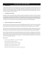
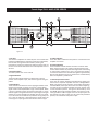
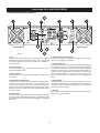
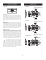
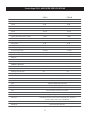
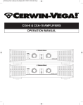
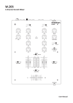
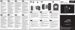
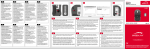
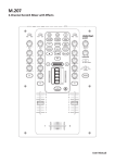
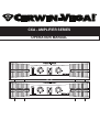
CXA - AMPLIFIER SERIES
OPERATION MANUAL
Cerwin-Vega! CXA - AMPLIFIER SERIES
1.
2.
3.
4.
5.
6.
7.
8.
9.
10.
11.
12.
13.
14.
15.
16.
17.
18.
19.
Read Instructions – All the safety and operating instructions should be read before this product is operated.
Retain Instructions – The safety and operating instructions should be retained for future reference.
Heed Warnings – All warnings on the appliance and in the operating instructions should be adhered to.
Follow Instructions – All operating and use instructions should be followed.
Water and Moisture – The appliance should not be used near water – for example, near a bathtub, washbowl, kitchen sink, laundry tub, in a wet basement,
or near a swimming pool, and the like.
Heat – Appliance should be situated away from heat sources such as radiators, heat registers, stoves, or other appliances (including amplifiers) that produce
heat.
Power Sources – This product should be operated only from the type of power source indicated on the rating label. If you are not sure of the type of power
supply to your home, consult your product dealer or local power company.
grounding or Polarization – This product may be equipped with a polarized alternation-current line plug (a plug having one blade wider than the other).
This plug will fit into the power outlet only one way. This is a safety feature. If you are unable to insert the plug fully into the outlet, try reversing the plug.
If the plug should still fail to fit, contact your electrician to replace your obsolete outlet. Do not defeat the safety purpose of the polarized plug.
Power-Cord Protection – Power-supply cords should be routed so that they are not likely to be walked on or pinched by items placed upon or against them,
paying particular attention to the cord in correspondence of plugs, convenience receptacles, and the point where they exit from the appliance.
Cleaning – The appliance should be cleaned only as recommended by the manufacturer. Clean by wiping with a cloth slightly damp with water. Avoid getting
water inside the appliance.
Non-use Periods – The power cord of the appliance should be unplugged from the outlet when left unused for a long period of time.
Object and Liquid Entry – Care should be taken so that objects do not fall and liquids are not spilled into the enclosure through openings.
Damage Requiring Service – The appliance should be serviced by qualified service personnel when:
A. The power-supply cord or the plug has been damaged; or
B. Objects have fallen, or liquid has been spilled into the appliance; or
C. The appliance has been exposed to rain; or
D. The appliance does not appear to operate normally or exhibits a marked change in performance; or
E. The appliance has been dropped, or the enclosure damaged.
Servicing – The user should not attempt any service to the appliance beyond that described in the operating instructions. All other servicing should be referred
to qualified service personnel.
Ventilation – Slots and openings in the cabinet are provided for ventilation and to ensure reliable operation of the product and to protect it from overheating,
and these openings must not be blocked or covered. The openings should never be blocked by placing the product on a bed, sofa, rug, or other similar surface.
This product should not be placed in a built-in installation such as a bookcase or rack unless proper ventilation is the manufacturer’s instructions have been
adhered to.
Attachments – do not use attachments not recommended by the product manufacturer as they may cause hazards.
Accessories – Do not place this product on an unstable cart, stand, tripod, bracket, or table. The product may fall, causing serious injury to a child or adult, and
serious damage to the product. Use only with a cart, stand, tripod, bracket, or table recommended by the manufacturer, or sold with the product. Any mounting
of the product should follow the manufacturer’s instructions, and should use a mounting accessory recommended by the manufacturer.
Replacement Parts – When replacement parts are required, be sure the service technician has used replacement parts specified by the manufacturer or have
the same characteristics as the original part. Unauthorized substitutions may result in fire, electric shock, or other hazards.
Safety Check – Upon completion of any service or repairs to this product, ask the service technician to perform safety checks to determine that the product is
in proper operating conditions.
20. This product is in compliance with EU WEEE regulations. Disposal of end of life product should not be treated as municipal
waste. Please refer to your localregulations for instructions on proper disposal of this product.
21. Carts and Stands – The appliance should be used only with a cart or stand that is recommended by the manufacturer. An appliance and
cart combination should be moved with care. Quick stops, excessive force, and uneven surfaces may cause the appliance and cart
combination to overturn.
22. The appliance coupler is used as the disconnect device, the disconnect device shall remain readily operable.
WARNINg
To reduce the risk of electric shock, do not expose this apparatus to rain or moisture. Ensure that the apparatus
is not exposed to splashing and that no objects filled with liquids, such as vases, are placed on the apparatus.
CAUTION
DO NOT OPEN
RISK OF ELECTRIC SHOCK
CAUTION: To reduce the risk of electric shock, do not remove any cover.
No user serviceable parts inside. Refer servicing to qualified personnel only.
The lighting flash with arrowhead symbol within the equilateral triangle is intended to alert the user to
the presence of un-insulated “dangerous voltage” within the product enclosure that may be significant
enough to constitute a risk of electric shock.
The exclamation point within the equilateral triangle is intended to alert the user to the presence of
important operation and maintance (servicing) instructions in the literature accompanying this
appliance.
CAUTION
To prevent electric shock, do not use this polarized plug with an extension cord, receptacle or other outlet unless the blades can be fully inserted to prevent blade exposure.
Cerwin-Vega! CXA - AMPLIFIER SERIES
1.
INTRODUCTION
Congratulations! Welcome to the Cerwin-Vega! family. You’ve joined a growing group of audio professionals who have
turned to Cerwin-Vega! for the most advanced audio reproduction systems available. All Cerwin-Vega! systems are
thoroughly tested to insure that they meet or exceed our performance specifications. Backed by the best service in the
industry, Cerwin-Vega! is dedicated to quality and reliability. For a complete overview of Cerwin-Vega! products, accessories,
and services, log onto www.cerwin-vega.com.
2.
UNPACKINg & INSTALLATION
Although it is neither complicated to install, nor difficult to operate your amplifier, a few minutes of your time are required
to read this manual for a properly wired installation, and to become familiar with the unit’s features. Please take great care
in unpacking the unit and do not discard the carton and other packing materials. They may be needed when moving the
unit and are required if it ever becomes necessary to return the unit for service. Never place the unit near a radiator, in front
of heating vents, in direct sunlight, in excessive humidity, or dusty locations to avoid damages and to guaranty a long reliable
use. Connect the unit with the system components according to the description on the following pages.
3.
ABOUT THE CERWIN-VEgA! CXA AMPLIFIER SERIES
The Cerwin-Vega! CXA-Series high performance stereo and bridgeable power amplifiers are for those that want to sound
like a pro! These home-use versions of the renowned Cerwin-Vega! Professional series amplifiers. The same capability for
shock and awe, but with input/output connections and a form factor suited for performing at home versus on stage.
These workhorses have the muscle to accommodate the most demanding audio challenges. With power ratings of up to
1800 watts* (for the CXA 8) and 2800 watts* (for the CXA 10), exceptional THD (Total Harmonic Distortion) and Signal-toNoise ratings, the CV Series power amps are the right choice for a wide range of music and home theater applications.
To ensure reliable operation the CXA amps include a highly efficient variable speed tunnel cooling system that dynamically
follows amplifier output levels. When unneeded, the fans shut down entirely thereby reducing ambient noise. The 21position detent level control knobs help you set and maintain volume settings. Signal and clip indicators provide a convenient
way to monitor the amplifier’s status. Proven professionally -- the CXA-Series Amps are right for the job – even when the
“job” is entertaining friends and family.
Main Features:
• Power ratings up to 2800 watts – run in stereo or bridged
• Professional quality design and reliability
• Flow-through cooling design prevents overheating
• Defeatable limiter and high pass filter per channel
• Detented 21-position input level control knobs
• Front panel LED indication of power, clip protect and signal status
1
Cerwin-Vega! CXA - AMPLIFIER SERIES
CXA AMPLIFIER FRONT PANEL DESCRIPTION
Figure 1.1
1. Fan Vent
The CV-Series amplifiers are cooled by two rear-mounted fans
(except for CV-900 which is cooled by a single rear mounted fan).
Cool air flows through the front fan filters, reducing the
temperature of internal components while forcing the heat out
the rear vents. Never block these vents and keep them clean at
all times.
5. Active Indicators
These blue LED's indicate that AC power is connected and the
amplifier is turned on.
6. Protect Indicators
These red LED's indicate that the channel is in Protect mode.
When the channel goes into protect mode all output for that
channel will be muted. The protect LED's light when overheating
or other severe problems occur. This is to protect any speakers
connected to the channel. The LED's also light for approximately
five seconds whenever the unit is powered on and fade slowly
when the amplifier is powered off.
2. AC Power Switch
This switch powers the unit on and off.
3. Signal Indicators
These blue LED's will illuminate to indicate that a signal is
present at the amplifier input, and that the signal is being amplified.
7. Channel input level control
These two 21-position detented potentiometers adjust input
level for their respective amplifier channels. In Bridged Mono
Mode, only channel 1 level control is used to adjust signal level.
In Parallel Mode, both input level control are used to adjust signal level for their respective amplifier channels. At their fully
counter-clockwise position, the signal is attenuated by more
than 80dB. At their fully clockwise position, the signal is at maximum gain.When 0 dBu of signal arrives at the input jacks and
the Channel input level controls are set to their fully clockwise
position, the unit delivers full power output.
4. Clip Indicators
These red LED's will illuminate at the clipping threshold. These
lights should not light up during normal use as they indicate
signal outside of the amplification range of the amplifier. When
a signal is "clipped" and the clip indicator illuminates, it means
that the signal is being distorted at the output stage. Prolonged
clipping can not only damage your amplifier, but also your speakers, so be careful to monitor the clip indicator during setup and
use. If the clip indicator is illuminated then simply lower the
channel gain or input signal until the indicator does not light.
2
Cerwin-Vega! CXA - AMPLIFIER SERIES
CXA AMPLIFIER REAR PANEL DESCRIPTION
Figure 1.2
1. Fan
This is a variable speed cooling fan. Cool air enters the amplifier
through the fan filters located on the front of the amplifier. Be
sure not to block these ports when installing the amplifier or
other equipment.
2. Input connectors
Connect the input source to the unbalanced RCA connectors
using standard RCA cables.
3. Link connectors
These jacks are used to send a parallel signal to another device
or amplifier.
4. High Pass Filter (HPF) switch.
These switches are used to activate the built-in High Pass Filter.
The HPF rolls off signals below 40Hz. This improves bass performance by limiting sub-audio cone motion, making more
power available for the speaker’s rated frequency range. When
the filter is turned off, a 5 Hz roll off protects against DC or deep
sub-audio inputs.
5. Limiter switch
When the input signal connected to your amplifier is too high,
you end up with a distorted output signal. To prevent this, both
channels feature a clip limiter that can be engaged or disengaged
selectively.
3
6. Bridge / Stereo / Parallel switch
This switch changes the amplifier operating mode between
stereo, mono bridged, and parallel.
7. 5-way Binding Post
Connect each channel of the unit to your speakers. Binding posts
are provided for each channel as so that paralleling of speakers
is possible. Connection to the binding posts can be made with
bare wire, banana plugs, or spade lug terminations. Make connections to both the Channel 1 and Channel 2 terminals for
Stereo or Parallel Mode, or a single connection across the red
terminals only of Channel 1 and Channel 2 for Bridged Mono
Mode.
8. Circuit breaker
The breaker acts in place of common disposable fuses. This circuit breaker will trip if there is a fault with the main voltage or if
maximum output is exceeded. Simply depress the circuit breaker
and power up the unit again.
9. AC input
IEC connector for AC power cable. Connect the supplied heavygauge 3-pin IEC power cable.
PROTECTION
Every model in the CV-Series incorporates protection features.
The front panel Protection LED indicates the activity of the
speaker connection relay circuitry in each channel.When the
protection LED turns on, this circuitry is active, and all connected
speakers are muted.
Initial power-up : For approximately five seconds after initial
power-up, the protection circuitry is activated and the speaker
outputs are muted. If everything is operating normally, you will
hear an audible click at the conclusion of this brief period, as the
protection circuitry is deactivated and the unit begins delivering
signal to the connected speakers. It is normal for the Protection
LED to fade gradually after the amplifier is powered off.
Thermal Protection : Abnormally high heat sink temperatures
will engage the protection circuitry for the overheating channel
only. An output relay disconnects the speakers until normal
temperature range is restored. The Protect indicator will light to
show the protection circuit is active. To guard against this
problem, make sure the unit receives adequate ventilation on
all sides and that both the front and rear panels are
unobstructed. If the power transformer gets too hot, its thermal
switch will disconnect all of the secondary power and disconnect
both channel outputs.
Short circuit : If output is shorted due to faulty wiring, the
thermal circuitry will automatically protect the amplifier. If this
occurs, the load will be disconnected by the thermal protection
circuitry.
DC Voltage Protection : If an amplifier channel detects DC
voltage at the speaker output, the output relay will immediately
open to prevent speaker damage.
Subsonic Frequency Protection : The built-in High Pass Filter
provides subsonic frequency protection for each channel.
Current limiting Protection : At the amplifier’s full power limit,
or clipping point, the limiter circuitry will be activated. This is
indicated by illumination of the Clip LED. The channel gain is
automatically reduced, protecting the speakers from high power.
Uncontrolled feedback, oscillations, or improper equipment gain
setting may activate this circuitry, which is virtually transparent
in operation as full signal bandwidth is maintained.
There is reason to be concerned any time the Protection LED
lights up (except for initial power-up during approximately five
seconds). If this occurs, turn the amplifier off immediately and
check all wiring and external equipment carefully in order to
locate and correct the condition.
SETUP
Clip limiter
HPF (Hi-Pass Filter)
Clipping is the result of an amplifier running into power supply
limitation. The maximum output voltage that any amplifier can
produce is limited by its power supply. Attempting to output a
voltage (or current) level that exceeds the power supply limit
will result in a flattening effect on the signal. A clipped waveform
exhibits extreme harmonic distortion, making it sound harsh or
dissonant. The clip limiter detects this and reduces the gain to
minimize the amount of overdrive. To preserve as much of the
program dynamics as possible, limiting reduces the average
program level until peaks barely clip. Each channel has its own
clip limiter, which can be switched on or off. When driving fullrange speakers, clip limiting reduces high frequency distortion
caused by bass overload. It also protects higher frequency
drivers from excess overdrive and harsh clipping harmonics.
Also known as a low-cut filter, a High Pass Filter rolls off signals
below 40Hz. The reproduction of the signal’s bass portion is thus
optimized, since ultra-low, distracting frequencies are
eliminated, and more power is available for the reproduction of
the wanted segment of the signal.
You should set up the filters so they best suit the frequency
response of your speakers, since some speakers are particularly
sensitive to over-excursion. The 40Hz filter works well with most
compact full-range speakers.
4
SETUP (CONTINUED)
CONNECTIONS
Mode Select
Stereo Mode
(5-Way Ouptut Binding Posts)
Stereo Mode
In stereo mode, both channels operate independently with individual input gain controls. Signal at channel 1’s input produces
output at channel 1, while signal at channel 2’s input produces
output at channel 2’s output. Recommended minimum nominal load impedance for stereo operation is 2 ohms per channel.
Parallel Mode
(5-Way Output Binding Posts)
Parallel Mode
When set to Parallel mode, a signal applied to channel 1’s input
will be amplified and appear at outputs for both channel 1 & 2.
The parallel mode is well suited for applications in which driving two speakers with the same signal but with separate amplification. The ‘Channel1’ and ‘Channel 2’ input gain controls
individually control the out put level on channels 1 and 2.
Bridged Mono Mode
Bridged mono mode straps both amplifier channels together
to make a very powerful, single-channel monaural amplifier.
One channel ”pushes” and the other channel “pulls” equally,
doubling the power over that of either channel alone. Therefore the voltage is doubled, the peak power is quadrupled, and
program power is roughly three times as high as that of the individual channel. Signal is applied to the channel 1 input only
and channel 1 input gain control is used to adjust signal level.
The input gain control belonging to channel 2 are not used.
Bridged Mono Mode
Note : Bridged mono mode is to be used only when
the CV-Series is connected to a 4 or 8 ohms speaker
load. Use of Bridged mode with speaker loads of less
than 4 ohms can result in severe damage to the unit
due to excessive heat and current limiting. Use extreme caution when operating the amplifier in Bridged Mono Mode.
Never ground either side of the speaker cable; the speaker load
must “ float “ away from the amplifier chassis.
5
(5-Way Output Binding Posts)
Cerwin-Vega! CXA - AMPLIFIER SPECIFICATIONS
CXA-8
CXA-10
Stereo Both Channels Driven
Output Power (RMS)
8 ohms
400 W
600 W
4 ohms
600 W
900 W
2 ohms
900 W
1400 W
Output Power (RMS)
Bridged Mono
8 ohms
1200 W
1800 W
4 ohms
1800 W
2800 W
Signal to Noise Ratio (20 Hz - 20k Hz)
102 dB
104 dB
Distortion (SMPTE-IM)
0.01%
0.04%
Input Sensitivity @ 8 ohms
4 dBu
4 dBu
Voltage Gain
33 dB
35 dB
Output Circuitry
Class AB
Class H
Current Consumption
240 Vac
@ 1/8 power @ 4 ohms
4.4 amps
3.4 amps
@ 1/3 power @ 4 ohms
6 amps
8.3 amps
@ Full power @ 4 ohms
9.5 amps
16 amps
20 Hz - 20k Hz @ 1/2 Power
0.01%
0.03%
1k Hz @ Full Power
0.10%
0.10%
Distortion
FREQUENCY RESPONSE
+/- 0.5 dB
20 Hz - 20 kHz
+/- 3 dB
Damping Factor (400 Hz)
5 Hz - 60 kHz
280
350
Input Impedance
15k ohm Un-balanced / 30k ohm balanced
Input Clipping
22 dBu (10 Vrms)
Cooling
Continuously variable speed fan, front to rear
CONNECTORS
Input
Unbalanced RCA input and link out
Output
5-way binding post
CONTROLS
Front
AC power switch / Channel 1 & 2 volume
Rear
HPF Switch / Limiter Switch / Mode Selector Switch
Indicators
Power On: Light Blue / Signal: Dark Blue / Limit-Clip: Red
Protection
Short Circuit / Thermal / Current Limit resetable breaker / DC offset /
Current In-Rush / RF Protection / On-Off Mute
Power Requirements
240 Vac 50 Hz
Dimensions
Net Weight
482 mm X 88 mm X 420 mm
18 Kg
6
20.7 Kg
772 S. Military Trail • Deerfield Beach, FL 33442
Phone: +1 (954) 949-9601
Fax: +1 (954) 949-9590
E-mail: [email protected]
www.cerwin-vega.com
LITH00023
CXA OWNERS MANUAL