1
83 41 77_12 GB04.04.qxd
22.09.2004 12:34 Uhr
Seite 51
Parts replacement 9
9 Parts replacement
9.2 Replacement of burner
Ensure that ALL regulations are observed.
9.1 Safety instructions
The following safety instructions are to be followed
when installing replacement parts!
Important:
Before starting any maintenance work:
Isolate the mains electricity supply by disconnecting the plug at the socket outlet (if
there is only an isolating switch remove the fuse
from the switch).
• Turn off the gas supply at the gas service valve fitted
to the boiler.
• When removing any water carrying components ensure
that water is kept away from all electrical components.
• Always use new seals and O–rings when replacing parts.
• Always test for gas soundness and always carry out
functional checks after any service work and after
exchanging any gas carrying component.
• Always check earth continuity, polarity and resistance
to earth with a multimeter after any service work and
after exchanging any electrical component.
9.1.1 Initial preparation
• Turn off the boiler.
• Isolate the electrical supply to the boiler.
• Remove boiler bottom cover.
• Turn off the gas service valve.
• Turn off the boiler CH service valves.
• Turn off the cold water inlet service valve (ecoMAX 800).
• Remove front case
• Lower electronic control box.
• Release central heating water pressure by draining the
boiler from the drain points provided. (This needs only
to be carried out when detailed in these instructions).
• After installing replacement parts, recommission and
check boiler function as described in commissioning
section.
Note:
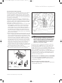
The boiler is fitted with a combustion analysis
test point. A suitable combustion analyser can
be connected at this point to establish the combustion performance of the boiler.
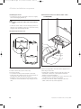
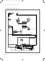
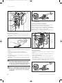
9.1.2 Removal of burner assembly
• Remove screw and disconnect air inlet pipe.
• Disconnect gas supply from gas valve by undoing union.
• Disconnect HT lead and earth lead from spark electrode.
• Remove five nuts from burner manifold.
• Disconnect two electrical connections from fan and
gas valve.
• Pull forward complete burner, gas valve and fan assembly.
• Remove burner, gas valve and fan assembly from boiler.
Instructions for installation and servicing ecoMAX
1
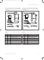
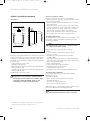
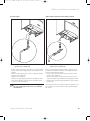
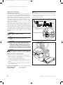
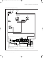
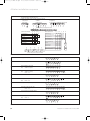
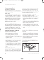
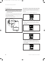
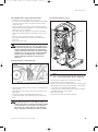
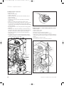
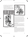
Fig. 9.1 Replacing the burner
•
•
•
•
•
•
•
•
Turn off boiler.
Remove front casing.
Lower control box.
Remove burner, gas valve and fan assembly as previously detailed.
Remove 4 screws (1) securing burner to burner manifold.
Fit new burner to manifold using the new sealing gasket supplied, ensuring that the notch in the burner aligns with the burner viewing window.
Reassemble in reverse order.
Recommission boiler as detailed.
9.3 Replacement of fan
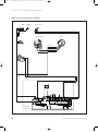
• Turn off boiler.
• Remove front casing.
• Lower control box.
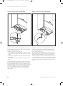
• Remove burner, gas valve and fan assembly as previously detailed.
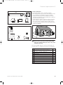
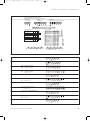
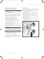
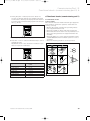
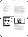
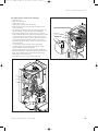
• Remove 4 screws (1).
• Separate gas valve and fan assembly from burner
manifold (2).
• Remove 2 screws (3) securing gas valve to fan.
• Fit gas valve to new fan using the new sealing gasket
supplied.
• Refit gas valve and fan assembly to burner manifold
using the new sealing gasket supplied. Equally tighten
the four screws (1) to ensure a good seal is made.
• Reassemble burner, gas valve and fan assembly in
reverse order.
• Recommission boiler as previously detailed.
51