1
Important: If you encounter any problems with this kit, DO NOT RETURN TO RETAILER. Call toll-free (800) 533-2441
or e-mail us at: [email protected]. Customer Service • 150 Carpenter Ave. • Wheeling, IL 60090 U.S.A.
WARNING: Always check your wiring before
turning on a circuit. Never leave a circuit
unattended while the batteries are installed.
Never connect additional batteries or any
other power sources to your circuits.
!
WARNING:
CHOKING HAZARD - Small parts.
Not for children under 3 years.
Conforms to all applicable U.S. government
requirements.
• Do not short circuit the battery
terminals.
• Never throw batteries in a fire or
attempt to open its outer casing.
• Non-rechargeable batteries should not
be recharged. Rechargeable batteries
should only be charged under adult
supervision, and should not be
recharged while in the product.
• Use only 1.5V “AA” type, alkaline
batteries (not included).
• Do not mix old and new batteries.
• Insert batteries with correct polarity.
• Remove batteries when they are used
up.
• Do not mix alkaline, standard (carbonzinc),
or
rechargeable
(nickelcadmium) batteries.
• Batteries are harmful if swallowed, so
keep away from small children.
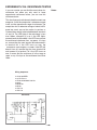
I. PLAYGROUND OF ELECTRONIC CIRCUITS
1. Woodpecker
2. Police Siren
3. Metronome
4. Grandfather Clock
5. Harp
6. Tweeting Bird
7. Meowing Cat
8. Callin’ Fish
9. Strobe Light
10. Sound Effects for Horror Movies
11. Machine Gun Oscillator
12. Motorcycle Mania
13. Vision Test
14. Patrol Car Siren
Page 4
4
5
5
9
10
10
III. LED DISPLAY CIRCUITS
23. LED Display Basics
24. Digital Display Circuit for the Seven-Segment LED
25. LED Display with CdS and Transistor
26. Switching the LED Display Using Transistor Control
IV. WELCOME TO DIGITAL CIRCUITS
27. “Flip-Flop” Transistor Circuit
28. “Toggle Flip-Flop” Transistor
29. “AND” Diode Transistor Logic with LED Display
30. “OR” DTL Circuit with Display
31. “NAND” DTL Circuit with Display
32. “NOR” Transistor Circuit with Display
33. “Exclusive OR” DTL Circuit
11
12
13
14
15
16
17
18
19
20
21
22
23
24
25
II. BASIC ELECTRONICS CIRCUITS
26
A MAJOR CHANGE
15. Dimming the Light
16. Flip Flopping
17. Capacitor Discharge Flash
18. Transistor Action
19. Series and Parallel Capacitors
20. Transistor Switching
21. Series and Parallel Resistors
22. Amplify the Sound
27
28
29
30
31
32
33
34
35
V. MORE FUN WITH DIGITAL CIRCUITS
34. “BUFFER” GATE using TTL
35. “INVERTER” GATE using TTL
36. “AND” GATE using TTL
37. “OR” GATE using TTL
38. “R-S Flip-Flop” using TTL
39. “Triple-Input AND” Gate using TTL
40. “AND” Enable Circuit using TTL
41. “NAND” Enable Circuit using TTL
42. “NOR” Enable Circuit using TTL
43. “NAND” Gate Making a Toggle Flip-Flop
44. “Exclusive OR” GATE using TTL
45. “OR” Enable Circuit using TTL
46. Line Selector using TTL
47. Data Selector using TTL
-2-
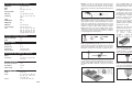
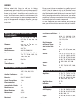
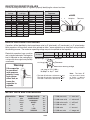
Use the following information as a guide in properly identifying the value of resistors.
BAND 1
1st Digit
Batteries:
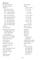
TABLE OF CONTENTS
Before We Begin
Installing the Batteries
Making Wire Connections
Components
Building Your First Project
Troubleshooting
Helpful Suggestions
IDENTIFYING RESISTOR VALUES
Color
Black
Brown
Red
Orange
Yellow
Green
Blue
Violet
Gray
White
BAND 2
2nd Digit
Digit
0
1
2
3
4
5
6
7
8
9
Color
Black
Brown
Red
Orange
Yellow
Green
Blue
Violet
Gray
White
Multiplier
Digit
0
1
2
3
4
5
6
7
8
9
Color
Black
Brown
Red
Orange
Yellow
Green
Blue
Silver
Gold
Resistance
Tolerance
Multiplier
1
10
100
1,000
10,000
100,000
1,000,000
0.01
0.1
Color
Silver
Gold
Brown
Red
Orange
Green
Blue
Violet
Tolerance
±10%
±5%
±1%
±2%
±3%
±0.5%
±0.25%
±0.1%
BANDS
2
1
Multiplier
Tolerance
36
37
38
39
40
IDENTIFYING CAPACITOR VALUES
Capacitors will be identified by their capacitance value in pF (picofarads), nF (nanofarads), or μF (microfarads).
Most capacitors will have their actual value printed on them. Some capacitors may have their value printed in
the following manner. The maximum operating voltage may also be printed on the capacitor.
41
42
43
44
45
46
47
48
49
50
51
52
53
54
55
56
57
58
59
60
61
62
63
Electrolytic capacitors have a positive
and a negative electrode. The negative
lead is indicated on the packaging by
a stripe with minus signs and possibly
arrowheads.
Multiplier
For the No.
0
1
2
3
Multiply By
1
10
100
1k
Second Digit
First Digit
Warning:
If the capacitor
is connected
with incorrect
polarity, it may
heat up and
either leak, or
cause the
capacitor to
explode.
4
5
8
10k 100k .01
Means
pico
nano
micro
milli
unit
kilo
mega
0.1
Multiplier
103K
100V
Tolerance*
Maximum Working Voltage
The value is 10 x 1,000 =
10,000pF or .01μF 100V
Polarity
Marking
* The letter M indicates a tolerance of +20%
The letter K indicates a tolerance of +10%
The letter J indicates a tolerance of +5%
Note: The letter “R”
may be used at times
to signify a decimal
point; as in 3R3 = 3.3
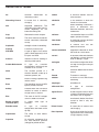
METRIC UNITS AND CONVERSIONS
Abbreviation
p
n
μ
m
–
k
M
9
Multiply Unit By
.000000000001
.000000001
.000001
.001
1
1,000
1,000,000
Or
10-12
10-9
10-6
10-3
100
103
106
-159-
1. 1,000 pico units
= 1 nano unit
2. 1,000 nano units
= 1 micro unit
3. 1,000 micro units
= 1 milli unit
4. 1,000 milli units
= 1 unit
5. 1,000 units
= 1 kilo unit
6. 1,000 kilo units
= 1 mega unit