1
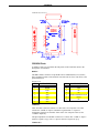
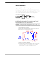
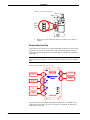
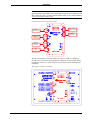
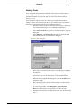
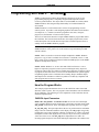
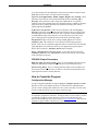
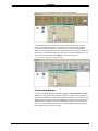
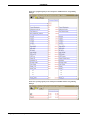
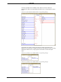
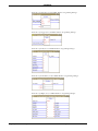
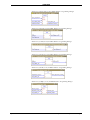
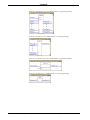
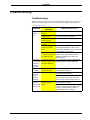
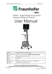
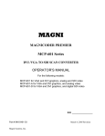
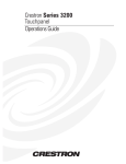
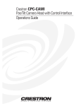
CRESTRON Contents Expanded Video Adapter: CNXVGA 1 Description................................................................................................................................. 1 Functional Description ................................................................................................ 1 Physical Description.................................................................................................... 1 Leading Specifications............................................................................................................... 4 Installation ................................................................................................................................. 4 Equipment ................................................................................................................... 4 Special Applications.................................................................................................... 5 Preparation for Use...................................................................................................... 6 Identity Code ............................................................................................................... 8 Programming with SIMPL™ Windows ................................................................................. 9 How the Program Works............................................................................................. 9 How to Create the Program ....................................................................................... 10 Problem Solving ...................................................................................................................... 17 Troubleshooting ........................................................................................................ 17 Further Inquiries........................................................................................................ 18 Return and Warranty Policies.................................................................................................. 19 Merchandise Returns / Repair Service ...................................................................... 19 CRESTRON Limited Warranty ................................................................................ 19 Operations Guide - DOC. 8134A Contents • i CRESTRON Expanded Video Adapter: CNXVGA Description Functional Description The CNXVGA is an expanded video graphic adapter (or scan converter) made for use with Crestron’s VT-3500 and VT-3500L video touchpanels. With the addition of a CNXVGA any VT-3500/L becomes a cost effective computer graphic or multimedia touchpanel. The CNXVGA accepts RGB video in standard DOS, VGA, SVGA, XGA, and MAC formats (from 640 x 480 to 1024 x 768 resolution) and outputs either composite or S-Video. Maximum rate with defined resolution is XGA at 72 Hz. Higher rates are available at lower resolution. The unit works with RGBHV and RGBS. The CNXVGA has network adjustable parameters for each video format identified. Flash memory in the unit stores the parameters for up to 25 formats. A single external recessed button is used to cycle between the RGB port and video port. Physical Description The CNXVGA, shown on the next page, is housed in a black enclosure with a silkscreened top panel. The high density 15-pin female RGB IN, four coaxial cable ports for VIDEO IN and VIDEO OUT, and an 8-position RJ45 (for VT-3500 only) modular jack is located on one side of the unit. Two 4-pin network connectors are located on the opposite side. Five LEDs are located on the top panel to provide the unit’s status. Below the LEDs, there is a single button used for local control. At the shorter sides of the CNXVGA, the enclosure extends to form feet at a right angle to the side. There are three holes per foot for inserting screws when mounting to a VT3500L or stabilizing the device on a flat surface when connected to a VT-3500. Operations Guide - DOC. 8134A Expanded Video Adapter: CNXVGA • 1 CRESTRON CNXVGA Physical Views CNXVGA Ports A number of ports are provided on the side panels of the CNXVGA. Refer to the descriptions of each below. RGB IN This DB15 female connector accepts RGB video in standard (DOS, VGA, SVGA, XGA) and MAC formats with resolution from 640 x 480 to 1024 x 768. Refer to the pinout table below. RGB IN Pinout PIN DESCRIPTION PIN DESCRIPTION 1 RED 9 NC 2 GREEN 10 GND 3 BLUE 11 NC 4 NC 12 NC 5 GND 13 HSYNC/COMPOSITE SYNC 6 GND 14 VSYNC 7 GND 15 NC 8 GND NC = Not Connected VIDEO IN These two BNC connectors connect to a video source for composite or S-Video. Connect the “COMP Y” input to a luminance signal and the “C” input to a chrominance signal of an external S-Video source. For composite video use the “COMP Y”input only. The input impedance on both BNC connectors is 75 ohms. The “COMP Y” input is rated for a signal 1.0 Vp-p. The “C” input is rated for a signal 0.28 Vp-p. VIDEO OUT 2 • Expanded Video Adapter: CNXVGA Operations Guide - DOC. 8134A CRESTRON These two BNC connectors connect to the two VIDEO port connectors of the VT3500L for composite or S-Video. These connectors should not be used if the CNXVGA is connected to the VT-3500. The load impedance on both BNC connectors is 75 ohms. The “COMP Y” output is a luminance or composite signal, 1.0 Vp-p. The “C” output is the chrominance signal, 0.28 Vp-p. NOTE: The video output is configured for S-Video from the factory to provide the best result from the scan converter. Make sure the VT-3500 or VT-3500L that is connected is configured to accept S-Video through the on-screen setup menus. TIP: If the application requires the video output to be composite rather than SVideo, a single internal jumper can configure the CNXVGA to output the scanconverted image as a composite signal. Refer to “Special Applications” on page 5 for details. NET There is an 8-position, 8-pin RJ45 connector on one side of the CNXVGA that connects to the VT-3500 directly. This connector should not be used if the CNXVGA is connected to the VT-3500L. There are two 4-pin network connectors on the opposing side. The dual network connectors are pass through. One connector connects to the CRESNET control network. The other connects to the VT-3500L (if this VideoTouch configuration is used) or to other Crestron equipment (if the VT-3500 is connected and daisy chaining additional devices is necessary). CNXVGA Indicators A number of indicators are provided on the top panel of the CNXVGA. Refer to the descriptions of each below. PWR (Power) This LED illuminates when power is applied to the CNXVGA. NET This LED illuminates when there is network activity involving the CNXVGA. VIDEO This LED illuminates when the internal multiplexer is set to display the composite or S-Video source. RGB This LED illuminates when the internal multiplexer is set to display the RGB source. LOCAL This LED illuminates when the CNXVGA is under local control. CNXVGA Local Button A single recessed button is used to cycle between RGB and video. Operations Guide - DOC. 8134A Expanded Video Adapter: CNXVGA • 3 CRESTRON Leading Specifications The table below provides a summary of leading specifications for the CNXVGA. Dimensions and weight are rounded to the nearest hundredth unit. Leading Specifications of the CNXVGA SPECIFICATION Power Requirements Maximum Rate Flash Memory Default Network ID CNXVGA Firmware SIMPL Windows CNX Operating System CNX Monitor CNMS, CNRACK, CNLCOMP Operating System ST-CP Operating System ST-CP Monitor Dimensions Weight DETAILS 24 VDC, network power; 7.5 Watts XGA at 72 Hz Stores parameters for up to 25 formats 38 Version 1.26 or higher Version 1.21.04 or later Version 5.01.00 or later Version 2.00 or later Version 3.16.08 or later Version 4.00.29 or later Version 1.29 or later Height: 7.54 in (19.15 cm) Width: 4.16 in (10.57 cm) - excluding connectors Depth: 1.27 in (3.22 cm) 0.47 lb (0.21 cm) As of the date of manufacture, the unit has been tested and found to comply with specifications for CE marking. NOTE: This device complies with part 15 of the FCC rules. Operation is subject to the following two conditions: (1) this device may not cause harmful interference, and (2) this device must accept any interference received, including interference that may cause undesired operation. Installation Equipment The CNXVGA is provided without any connecting cables; they must be purchased separately. Here are some suggested cable accessories for CNXVGA applications. Suggested Cables for the CNXVGA CONNECTION PORT MANUFACTURER MODEL DESCRIPTION RGB IN Extron VGA-M6'HR 15-pin HD VGA Male to VGA Male RGB IN Extron SYVGA/XGA VGA Male to 5 BNCs 4 • Expanded Video Adapter: CNXVGA Operations Guide - DOC. 8134A CRESTRON Special Applications The CNXVGA ships preconfigured to convert all RGB input signals to an S-Video output. Some applications require the RGB input signals to be converted to a composite video output. For example, consider an application where a computer image is provided to the CNXVGA. A composite video output signal is required so that it can be sent to the video switcher where the signal can be made available to multiple places as a video source. The block diagram below represents the aforementioned application. Example Application of the CNXVGA COMPUTER CNXVGA VIDEO SWITCHER TO A NUMBER OF LOCATIONS AS VIDEO SOURCES Changing the output format is easy; simply move the position of a single internal jumper. Complete the following steps to remove the CNXVGA cover and reconfigure the video output signal to provide composite video. The only tools required are a Phillips tip screw driver and grounding strap. CAUTION: The CNXVGA contains electrostatic sensitive devices (ESD); observe precautions for handling ESDs to avoid damaging the unit. 1. Place CNXVGA on a flat surface. 2. Remove four screws and four washers that secure cover to the unit. Location of Four Screws and Washers on the CNXVGA Operations Guide - DOC. 8134A 3. Remove cover and locate jumper (J9). 4. The default setting for the CNXVGA has the jumper covering pins 2 and 3 (lower two pins as shown in illustration on the next page). Reposition jumper to cover pins 1 and 2 (upper two pins). Expanded Video Adapter: CNXVGA • 5 CRESTRON Jumper Location and Pin Positions BNC RJ45 J1 J6 Y4 J9 PIN 1 PIN 2 PIN 3 U9 Y2 J9 U7 Y3 SW1 5. Replace cover onto CNXVGA and secure with four scews and four washers. Preparation for Use Connections to the CNXVGA vary slightly depending on whether the unit is being used with a VT-3500 or VT-3500L. Refer to the two hookup diagrams after this paragraph. Other than making the power connection last, complete the connections in any order. NOTE: Before making any connections, review latest revision of network interconnection drawing (Doc. 5411) when making connections to the port labeled NET. CNXVGA Hookup Connections with VT-3500 CONNECT TO ANY RGB SOURCE CONNECT TO CONTROL SYSTEM CONNECT TO OTHER CRESTRON EQUIPMENT CONNECT TO VIDEO SOURCE NOT USED CONNECT TO VT-3500 (USE SUPPLIED CABLE ASSEMBLY, P/N 15709) The CNXVGA has been specifically designed to replace the VT-3500IMC when connected to the VT-3500. Use four screws (#8-32, not supplied) to stabilize the CNXVGA to a flat surface. 6 • Expanded Video Adapter: CNXVGA Operations Guide - DOC. 8134A CRESTRON NOTE: When connecting the CNXVGA to the VT-3500L, it may be useful to add a right angle adapter (part number 351A505, BoMar or equivalent, not supplied) to the BNC connectors of the VT-3500L, labeled VIDEO. Doing so, may make installation of the unit into tight locations easier. CNXVGA Hookup Connections with VT-3500L CONNECT TO ANY RGB SOURCE CONNECT TO CONTROL SYSTEM CONNECT TO NET PORT ON VT-3500L CONNECT TO VIDEO SOURCE CONNECT TO VIDEO PORT ON VT-3500L NOT USED The only tool required to mount the CNXVGA to the VT-3500L is a Phillips tip screwdriver. As shown after this paragraph, the CNXVGA can be mounted directly onto the back side of a VT-3500L using two screws that are already attached to the touchpanel. Mounting the CNXVGA to a VT-3500L Operations Guide - DOC. 8134A Expanded Video Adapter: CNXVGA • 7 CRESTRON Identity Code Every equipment and user interface within the control system network requires a unique identity code (NET ID). These codes are recognized by a two-digit hexadecimal number from 03 to FE. The NET ID of each CNXVGA has been factory set to 38. If the application requires it, there are several ways to change the NET ID of a CNXVGA in the control system using the PC via VisionTools™ Pro or SIMPL™ Windows. Complete the following steps to change the NET ID. 1. Disconnect all network devices from the control system, except for the one CNXVGA that needs to have its NET ID code changed. 2. Select Tools | ViewPort to open the “Crestron Performance Viewport” dialog box. 3. Select Functions > Set Network ID. The software checks the baud rate and then opens the “Set Network ID” dialog box. “Set Network ID” Dialog Box 8 • Expanded Video Adapter: CNXVGA 4. Notice the list of current network devices in the dialog box. Highlight the CNXVGA. 5. The NET ID of the CNXVGA (default NET ID is 38) appears in the box below the list. Use the scroll arrow to assign another NET ID. 6. When the newly assigned NET ID appears, select the Set ID button to initiate the change. 7. The software responds with a successful message to confirm the new NET ID. 8. To verify this procedure, select Diagnostics | Report Network Devices. Confirm that the CNXVGA has a new NET ID code. 9. Reconnect other network or modular devices that were disconnected in step 1. Operations Guide - DOC. 8134A CRESTRON Programming with SIMPL™ Windows SIMPL (Symbol Intensive Master Programming Language) is an easy-to-use programming language that is completely integrated and compatible with all Crestron system hardware. The objects that are used in SIMPL are called symbols. SIMPL Windows offers drag and drop functionality in a familiar Windows® environment. SIMPL Windows is Crestron Electronics' software for programming Crestron control systems. It provides a well-designed graphical environment with a number of workspaces (i.e., windows) in which a programmer can select, configure, program, test, and monitor a Crestron control system. The next two subsections describe a sample SIMPL Windows program that utilizes the CNXVGA. The first subsection details how the sample program works with a textual description. The second subsection provides a broad description of how to actually create the SIMPL Windows program. NOTE: The following description assumes that the reader has knowledge of SIMPL Windows. If not, please refer to the extensive help information provided with the software. NOTE: There is no need to recreate the sample touchpanel or SIMPL Windows program. A copy of each is available from Crestron’s ControlCD (version 5.1 and later). Search for or CNXVGA2.VTP and CNXVGA2.SMW projects in the SIMPL Windows Example Base directory. NOTE: SIMPL Windows v1.21.04 or later and CNXVGA firmware v1.26 or higher are required to program a control system containing the newly improved CNXVGA symbol. This new CNXVGA symbol must replace the CNXVGA symbol in programs created with earlier versions. The out-dated CNXVGA symbol appears in updated programs with a “CNXVGA OLD” heading. Keep in mind that inputs and outputs to the old and new CNXVGA symbol are not directly compatible and older programs may need to be reworked. How the Program Works The example program demonstrates how to use the CNXVGA and its associated functions within a system. The core program is based around the network definition for the CNXVGA. The following is a brief explanation of the CNXVGA network definition implementation. CNXVGA Input Parameters RGB, Video, Out_disable: The RGB and Video are used to select which input source should be displayed on the output using a momentary activation on the input. Out_disable can be used to “mute” the output and is typically driven off a toggle. In_Adj, Out_Adj: The input adjust allows the user to position and size each RGB image to best fit within the boundaries of the display. The Out_Adj is not typically needed when you use the CNXVGA to display on either the VT-3500 or VT-3500L touchpanels. If some other display device is used, it may be necessary to define the visible area of the screen. The Out_Adj allows adjustments to be made. All incoming signals and presets stored after making the adjustment will conform to the Operations Guide - DOC. 8134A Expanded Video Adapter: CNXVGA • 9 CRESTRON new output settings. For the adjustments to take place the CNXVGA must be in the RGB mode and one of these two inputs must be held high. Up, Down, Left, Right Width+, Width-, Height+, Height-, Save_Settings: These parameters only affect the selected aforementioned functions (either In_Adj or Out_Adj). These parameters make a single step adjustment for every positive transition on the corresponding input. Once the desired image is obtained, asserting a signal on the Save_Settings input stores the parameters into the preset memory location indicated by Preset#. In_Recenter, Out_Recenter: When used in conjunction with either In_Adj or Out_Adj, respectively, these functions allow the CNXVGA to try resyncing to the incoming signal while in adjustment mode. This is typically needed if adjustments are made and the image can no longer be viewed. This process provides a “best guess” starting point for adjustments based on the detected incoming signal. Out_Recenter simply restores factory settings of Out_Adj for the VT-3500. Autodetect_Off: The CNXVGA is set to auto detect all incoming signals by default. In the case of a stand-alone application this is needed to sense the incoming signal and adjust to its parameters on the fly. If an application program requires discrete preset selections, Autodetect_Off should be held high. Preset_1 Through Preset_25, Clear_Preset: To use discrete preset selections, Autodetect_Off must be low. Clear_Preset can be used to erase all of the settings in the selected preset memory. CNXVGA Output Parameters RGB_On, Video_On, Preset_Empty: These are true feedback indicators from the CNXVGA indicating the output selection and current selected memory status. Preset#, Vfreq, Hfreq: These are analog parameters that provide an indication of the currently selected preset memory location as well as the horizontal and vertical input frequencies that are currently detected. How to Create the Program Configuration Manager Use the Configuration Manager workspace (Project | Configure System) in SIMPL Windows to select and configure all the devices that need to be included into the system. For this example, add a CNXVGA to the system. Also add a VT-3500 to the system; its NET ID must be set to 03, shown on the next page. NOTE: SIMPL Windows v1.21.04 or later and CNXVGA firmware v1.26 or later are required to program the CNXVGA. If using an earlier version of either, Crestron recommends an upgrade of both. The latest versions can be obtained from the Software Downloads page of Crestron’s website (www.crestron.com). New users are required to register in order to obtain access to the FTP site. 10 • Expanded Video Adapter: CNXVGA Operations Guide - DOC. 8134A CRESTRON System View of VT-3500 in SIMPL Windows’ Configuration Manager As mentioned earlier, all CNXVGAs are factory set with the NET ID set to 38. However, in SIMPL™ Windows, the default can be changed while adding a CNXVGA to the control system. In the System Views area of the Configuration Manager, the CNXVGA NET ID can be altered in the “Device Settings” dialog box, shown below. To obtain the dialog box, right mouse click on the CNXVGA icon in the System Views area and select configure. Chose the NET ID tab. “Device Settings” Dialog Box in SIMPL Windows Programming Manager Use the Programming Manager workspace (Project | Program System) in SIMPL Windows to select symbols and assign their respective signals. For this example, a touchpanel and CNXVGA symbols were added automatically when the devices were added to the system in the Configuration Manager workspace. Expand the Network Modules folder and double click on the touchpanel for a detail view (alternatively CTRL+D or drag and drop into Detail View). Assign digital and analog signals to the touchpanel as shown on the next page. Operations Guide - DOC. 8134A Expanded Video Adapter: CNXVGA • 11 CRESTRON Detail View of Digital Signals for the Touchpanel in SIMPL Windows’ Programming Manager Detail View of Analog Signals for the Touchpanel in SIMPL Windows’ Programming Manager 12 • Expanded Video Adapter: CNXVGA Operations Guide - DOC. 8134A CRESTRON From the expanded Network Modules folder double click on the CNXVGA (alternatively CTRL+D or drag and drop into Detail View). Assign signals as shown below. Detail View of the CNXVGA in SIMPL Windows’ Programming Manager Expand the Logic folder to display the numerous symbols integrated into this program. View each of the 17 symbols in detail view (alternatively CTRL+D or drag and drop into Detail View). Assign signals as shown below and on subsequent pages. Detail View of an OR (S-1.1) in SIMPL Windows’ Programming Manager Detail View of an OR (S-1.2) in SIMPL Windows’ Programming Manager Operations Guide - DOC. 8134A Expanded Video Adapter: CNXVGA • 13 CRESTRON Detail View of a One Shot (S-1.3) in SIMPL Windows’ Programming Manager Detail View of a Toggle (S-1.4) in SIMPL Windows’ Programming Manager Detail View of an OR (S-1.5) in SIMPL Windows’ Programming Manager Detail View of an Oscillator (S-1.6) in SIMPL Windows’ Programming Manager Detail View of a Buffer (S-1.7) in SIMPL Windows’ Programming Manager 14 • Expanded Video Adapter: CNXVGA Operations Guide - DOC. 8134A CRESTRON Detail View of an Interlock (S-1.8) in SIMPL Windows’ Programming Manager Detail View of an AND (S-1.9) in SIMPL Windows’ Programming Manager Detail View of a NOR (S-1.10) in SIMPL Windows’ Programming Manager Detail View of an and (S-1.11) in SIMPL Windows’ Programming Manager Detail View of an OR (S-1.12) in SIMPL Windows’ Programming Manager Detail View of a Buffer (S-1.13) in SIMPL Windows’ Programming Manager Operations Guide - DOC. 8134A Expanded Video Adapter: CNXVGA • 15 CRESTRON Detail View of an Interlock (S-1.14) in SIMPL Windows’ Programming Manager Detail View of an OR (S-1.15) in SIMPL Windows’ Programming Manager Detail View of a Debounce (S-1.16) in SIMPL Windows’ Programming Manager Detail View of a NOR (S-1.17) in SIMPL Windows’ Programming Manager 16 • Expanded Video Adapter: CNXVGA Operations Guide - DOC. 8134A CRESTRON Problem Solving Troubleshooting The table below provides corrective action for possible trouble situations. If further assistance is required, please contact a Crestron technical support representative. CNXVGA Toubleshooting TROUBLE Touchpanel display is dark. Adjustments do not stretch image to the full height of the screen. Image garbled or unstable. Displayed signal has moving or stationary noise bars. Output is only black and white for RGB output source. Operations Guide - DOC. 8134A POSSIBLE CAUSE(S) CORRECTIVE ACTION Backlight timeout has elapsed. Screen brightness is improperly set. CNXVGA is not receiving power. CNXVGA is not wired properly. CNXVGA is not set to display the desired input. Touch screen to reactivate. Scan rate of the input signal is too high. Interference or noise. Lower vertical refresh rate. Do not exceed 72 Hz for XGA resolution. Relocate the CNXVGA away from any electromechanical devices. Relocate cable connecting the CNXVGA to the VT-3500 so that it is not near power feeds or other noise generating sources. Use Setup menu to adjust the touchpanel to properly display S-Video. If display is not a touchpanel and can only show a composite signal, change internal jumper to composite setting. Refer to "Special Applications" on page 5. Enter SETUP MODE and alter screen brightness from the Setup Menu. Confirm that power is supplied. Verify correct wiring to all connectors. If CNXVGA is NOT under Cresnet control depress the local button to switch to the correct input. Otherwise, use control system to select RGB or video source. CNXVGA ID is not set Enter Performance Viewport and poll the to match the NET ID in network. Verify that the NET ID for the the SIMPL program. CNXVGA is properly set to match the SIMPL program. Input signal uses low- Can not be corrected with adjustments to resolution DOS format CNXVGA. Must use higher resolution. (less than 480 lines). Output display is not showing S-Video signal. Expanded Video Adapter: CNXVGA • 17 CRESTRON Further Inquiries If after reviewing this Operations Guide for the CNXVGA, you cannot locate specific information or have questions, please take advantage of Crestron's award winning technical support team by calling: • In the US and Canada, call Crestron’s corporate headquarters at 1-888-CRESTRON [1-888-273-7876] or 1-201-767-3400. • In Europe, call Crestron International at +32-15-50-99-50. • In Asia, call Crestron Asia at +852-2341-2016. • In Latin America, call Crestron Latin America at +5255-5093-2160. • In Australia, call Crestron Pacific at +613-9480-2999. For local support from exclusive Crestron factory-trained personnel in New Zealand call Amber Technologies at +649-410-8382. 18 • Expanded Video Adapter: CNXVGA Operations Guide - DOC. 8134A CRESTRON Return and Warranty Policies Merchandise Returns / Repair Service 1. No merchandise may be returned for credit, exchange, or service without prior authorization from CRESTRON. To obtain warranty service for CRESTRON products, contact the factory and request an RMA (Return Merchandise Authorization) number. Enclose a note specifying the nature of the problem, name and phone number of contact person, RMA number, and return address. 2. Products may be returned for credit, exchange, or service with a CRESTRON Return Merchandise Authorization (RMA) number. Authorized returns must be shipped freight prepaid to CRESTRON, Cresskill, N.J., or its authorized subsidiaries, with RMA number clearly marked on the outside of all cartons. Shipments arriving freight collect or without an RMA number shall be subject to refusal. CRESTRON reserves the right in its sole and absolute discretion to charge a 15% restocking fee, plus shipping costs, on any products returned with an RMA. 3. Return freight charges following repair of items under warranty shall be paid by CRESTRON, shipping by standard ground carrier. In the event repairs are found to be nonwarranty, return freight costs shall be paid by the purchaser. CRESTRON Limited Warranty CRESTRON ELECTRONICS, Inc. warrants its products to be free from manufacturing defects in materials and workmanship under normal use for a period of three (3) years from the date of purchase from CRESTRON, with the following exceptions: disk drives and any other moving or rotating mechanical parts, pan/tilt heads and power supplies are covered for a period of one (1) year; touchscreen display and overlay components are covered for 90 days; batteries and incandescent lamps are not covered. This warranty extends to products purchased directly from CRESTRON or an authorized CRESTRON dealer. Purchasers should inquire of the dealer regarding the nature and extent of the dealer's warranty, if any. CRESTRON shall not be liable to honor the terms of this warranty if the product has been used in any application other than that for which it was intended, or if it has been subjected to misuse, accidental damage, modification, or improper installation procedures. Furthermore, this warranty does not cover any product that has had the serial number altered, defaced, or removed. This warranty shall be the sole and exclusive remedy to the original purchaser. In no event shall CRESTRON be liable for incidental or consequential damages of any kind (property or economic damages inclusive) arising from the sale or use of this equipment. CRESTRON is not liable for any claim made by a third party or made by the purchaser for a third party. CRESTRON shall, at its option, repair or replace any product found defective, without charge for parts or labor. Repaired or replaced equipment and parts supplied under this warranty shall be covered only by the unexpired portion of the warranty. Except as expressly set forth in this warranty, CRESTRON makes no other warranties, expressed or implied, nor authorizes any other party to offer any other party to offer any warranty, including any implied warranties of merchantability or fitness for a particular purpose. Any implied warranties that may be imposed by law are limited to the terms of this limited warranty. This warranty statement supercedes all previous warranties. Trademark Information All brand names, product names, and trademarks are the sole property of their respective owners. Windows is a registered trademark of Microsoft Corporation. Windows95/98/Me/XP and WindowsNT/2000 are trademarks of Microsoft Corporation. Operations Guide - DOC. 8134A Expanded Video Adapter: CNXVGA • 19