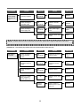
1
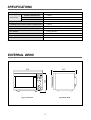
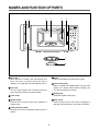
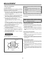
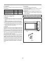
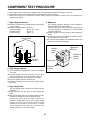
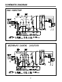
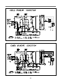
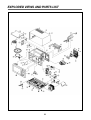
S/M No. : G875T2S001
Service Manual
Microwave Oven
Model: KOG-875T2S
DAEWOO ELECTRONICS CO., LTD.
http : //svc.dwe.co.kr
Feb. 2002
PRECAUTIONS TO BE OBSERVED BEFORE AND
DURING SERVICING TO AVOID POSSIBLE
EXPOSURE TO EXCESSIVE MICROWAVE ENERGY
(a) Do not operate or allow the oven to be operated with the door open.
(b) Make the following safety checks on all ovens to be serviced before activating the magnetron or other microwave source, and make repairs as necessary: (1) Interlock operation, (2) proper door closing, (3) seal and
sealing surfaces (arcing, wear, and other damage), (4) damage to or loosening of hinges and latches, (5)
evidence of dropping or abuse.
(c) Before turning on microwave power for any service test or inspection within the microwave generating compartments, check the magnetron, wave guide or transmission line, and cavity for proper alignment, integrity,
and connections.
(d) Any defective or misadjusted components in the interlock, monitor, door seal and microwave generation and
transmission systems shall be repaired, replaced, or adjusted by procedures described in this manual before
the oven is released to the owner.
(e) A microwave leakage check to verify compliance with the Federal Performance Standard should be
performed on each oven prior to release to the owner.
TABLE OF CONTENTS
PROPER USE AND SERVICE PRECAUTIONS .......................................................................................................................2
SPECIFICATIONS.......................................................................................................................................................................3
EXTERNAL VIEWS.....................................................................................................................................................................3
NAMES AND FUNCTION OF PARTS........................................................................................................................................4
CONTROL PANEL ......................................................................................................................................................................5
INTERLOCK MECHANISM FUNCTIONS AND ADJUSTMENTS .............................................................................................6
PRECAUTIONS FOR DISASSEMBLY AND REPAIR ...............................................................................................................8
DISASSEMBLY AND ASSEMBLY..............................................................................................................................................9
TROUBLE SHOOTING GUIDE ................................................................................................................................................17
MEASUREMENT ......................................................................................................................................................................23
COMPONENT TEST PROCEDURE ........................................................................................................................................25
WIRING DIAGRAM ...................................................................................................................................................................26
SCHEMATIC DIAGRAM ...........................................................................................................................................................27
EXPLODED VIEWS AND PARTS LIST ...................................................................................................................................29
PRINTED WIRING BOARD ......................................................................................................................................................32
P.C.B. CIRCUIT DIAGRAM ......................................................................................................................................................37
P.C.B. ASS’Y PART LIST .........................................................................................................................................................38
1
PROPER USE AND SERVICE PRECAUTIONS
1. For Safe Operation
Damage that allows the microwave energy (that cooks or heats the food) to escape will result in poor cooking and may
cause serious bodily injury to the operator.
IF ANY OF THE FOLLOWING CONDITIONS EXIST, OPERATOR MUST NOT USE THE APPLIANCE.
(Only a trained service personnel should make repairs.)
1) A broken door hinge.
2) A broken door viewing screen.
3) A broken front panel, oven cavity.
4) A loosened door lock.
5) A broken door lock.
The door gasket plate and oven cavity surface should be kept clean.
No grease, soil or spatter should be allowed to build up on these surfaces or inside the oven.
DO NOT ATTEMPT TO OPERATE THIS APPLIANCE WITH THE DOOR OPEN. The microwave oven has concealed
switches to make sure the power is turned off when the door is opened. Do not attempt to defeat them.
DO NOT ATTEMPT TO SERVICE THIS APPLIANCE UNTIL YOU HAVE READ THIS SERVICE MANUAL.
2. For Safe Service Procedures.
1) This microwave oven weight 17.6kg (38.9 lbs.) and must be placed on a horizontal base strong enough to support
this weight.
2) The oven should be placed as far from high temperature source and vapour as possible.
3) The power supply cord is about 1.1m (3.2ft) long. Earthing is required when connecting the power source.
4) Maximum power consumption of this oven is approximately 2.5Kw(230V). It is suggested that the unit is operated on
such power line (about 13 amperes) that can provide more power than this rating.
5) Object must not be placed on the top enclosure so as not to obstruct air flow for ventilation.
WARNING : This appliance must be earthed.
IMPORTANT
The wires in this mains lead coloured in accordance with the following code.
Green-and-yellow : Earth
Blue
: Neutral
Brown
: Live
As the colours of the wires in the mains lead of this appliance may not correspond with the coloured markings
identifying the terminals in your plug, proceed as follows:
The wire which is coloured green-and-yellow must be connected the the terminal in the plug which is marked with
the letter ‘E’ or by earth symbol or green-and-yellow.
The wire which is coloured blue must be connected to the terminal which is marked with the letter ‘N’ or coloured
black.
The wire which is coloured brown must be connected to the terminal which is marked with the letter ‘L’ or coloured
red.
NOTE : This oven is designed for counter-top use only.
2
SPECIFICATIONS
POWER SUPPLY
230V ~ , 50Hz single phase with earthing
MICROWAVE
POWER CONSUMPTION
1,400 W
OUTPUT POWER
900 W (IEC 705)
FREQUENCY
2,450 MHZ
GRILL POWER CONSUMPTION
1,400 W
COMBINATION HEATING POWER CONSUMPTION
1,400 W
OUTSIDE DIMENSIONS (W X D X H )
501 X 320 X 413 mm (19.7 X 12.6 X 16.2 in.)
CAVITY DIMENSIONS (W X D X H)
310 X 229 X 320 mm (12.2 X 9.0 X 12.6 in.)
NET WEIGHT
17.6 kg (38.9 Ibs.)
TIMER
60 minutes
SELECT FUNCTION
Microwave/Grill /Combination Heating
MICROWAVE POWER LEVEL
10 stages
* Specifications subject to change without notice.
EXTERNAL VIEWS
501
413
DEFROST
GRILL COMBI WEIGHT-TIME
M/W
GRILL
KG
WEIGHT
TIME
DEFROST DEFROST
COMBI
+1MIN
PROGRAM COOK
1. Roast Beef
2. Roast Port
3. Roast Chicken
4. Fish Fillets
5. Vegetable
320
M/W
PROGRAM
COOK
SPEEDY
COOK
STOP/CLEAR
START/CLOCK
Fig. 1 Front View
Fig. 2 Side View
3
NAMES AND FUNCTION OF PARTS
1 2
6
3
4
5
DEFROST
M/W
GRILL COMBI WEIGHT-TIME
PROGRAM
COOK
M/W
GRILL
KG
TIME
WEIGHT
DEFROST DEFROST
COMBI
+1MIN
PROGRAM COOK
1. Roast Beef
2. Roast Port
3. Roast Chicken
4. Fish Fillets
5. Vegetable
SPEEDY
COOK
STOP/CLEAR
START/CLOCK
7
8
9
1 Door latch
When the door is closed it will automatically lock
shut. If the door is opened while the oven is
operating. The magnetron will automatically shut off.
6 Heater
Grill or Combi-Mode has need for the heater.
7 Class cooking tray
Made of special heat resistant glass. The tray must
always be in proper position before operating. Do
not cook food directly on the tray.
2 Door seal
The door seal maintains the microwave within the
oven cavity and prevents microwave leakage.
3 Oven cavity
8 Roller guide
Supports the glass cooking tray.
4 Spatter shield
Protects the microwave outlet from splashes of
cooking foods.
9 Door screen
Allows viewing of food. The screen is designed so
that light can pass through, but not the microwaves.
5 Safety interlock system
Prevents the oven from operating while the door is
opened.
4
CONTROL PANEL
When blinking, the oven is
operating in WEIGHT
DEFROST.
When blinking, the oven is
operating in COMBI cooking.
When blinking, the oven is
operating in GRILL cooking.
DEFROST
When blinking, the oven is
operating in MICROWAVE
cooking.
When blinking, the oven is
operating in PROGRAM
cook.
Microwave Power Level Used to select the variable
microwave power level. If this
button is pressed for more
than 1.3 seconds, number is
scrolled up automatically.
M/W
GRILL COMBI WEIGHT-TIME
PROGRAM
COOK
M/W
GRILL
When blinking, the oven is
operating in TIME
DEFROST.
When blinking, the oven is
operating in weight input
mode.
KG
WEIGHT
TIME
DEFROST DEFROST
+1MIN
COMBI
When you touch this
button, Cooking time is
increased by the step of 1
minute.
PROGRAM COOK
1. Roast Beef
2. Roast Pork
3. Roast Chicken
4. Fish Fillets
5. Vegetable
Function Button - Used
to select desired oven
operation.
M/W
MICROWAVE
GRILL
SPEEDY
COOK
WEIGHT
DEFROST
COMBI
TIME
DEFROST
DIAL KNOB - Used to enter
the cooking time and weight
input.
+1 MIN
PROGRAM
COOK
STOP/CLEAR
START/CLOCK
Stop/Clear Button - Used
to pause or clear all
information manually put into
the oven.
GRILL
WEIGHT DEFROST
COMBINATION
TIME DEFROST
+1 MIN
PROGRAM COOK
Speedy Cook Button Used to quickly program
cooking time in 30
seconds increments.
Start/Clock Button Used to start operation
and to set the clock.
5
INTERLOCK MECHANISM FUNCTIONS AND ADJUSTMENTS
The door lock mechanism is a device which has been specially designed to completely eliminate microwave radiation when
the door is opened during operation, and thus to perfectly prevent the danger resulting from the leakage of microwave.
(1) Primary interlock switch
When the door is closed, the hook locks the oven door.
If the door is not closed properly, the oven will not operate.
When the door is closed, the hook pushes the lever downward.
The lever press the button of the primary interlock switch to bring it under ‘ON’ condition.
Mounting
screw
Hook
Primary
interlock
switch
6
(2) Monitor interlock switch
When the door is closed, the hook pushes the lever forward, and pushes the Latch Lever downward the lever press the
button of the interlock monitor switch to bring it under ‘OFF’ condition. The latch Lever press the button on the secondary
interlock switch to bring it under ‘ON’ condition.
- Adjustment
Interlock monitor switch
When the door is closed, the monitor switch should be opened before other switches close.
When the door is opened, the monitor switch should be closed after other switches open.
Adjustment steps :
a) Loosen the two mounting screws.
b) Adjust the interlock switch assembly position.
c) Make sure that the latch lever moves smoothly after adjustment is completed.
d) Completely tighten the two mounting screws.
7
PRECAUTIONS FOR DISASSEMBLY AND REPAIR
- Cautions to be observed when trouble shooting.
Unlike many other appliances, the microwave oven is high-voltage, high-current equipment. It is completely safe during
normal operation. However, carelessness in servicing the oven can result in an electric shock or possible danger from a
short circuit.
You are asked to observe the following precautions carefully.
(1) Always remove the power plug from the outlet before servicing.
(2) Use an insulated screwdriver and war rubber gloves when servicing the high voltage side.
(3) Warning about the electric charge in the high voltage capacitor. When inspecting and repairing the high voltage side,
always short the capacitor terminals and make sure of discharge.
1. Check the earthing.
Do not operate on a 2-wire extension cord.
The microwave oven is designed to be used when earthed.
It is imperative, therefore, to makes sure it is earthed
properly before beginning repair work.
2. Warning about the electric charge
in the high voltage capacitor.
For about 30 seconds after the operation stops, electric charge
remains in the high voltage capacitor. When replacing or
checking parts, short between oven chassis and the negative
high terminal of the high voltage capacitor, by using a properly
insulated screw driver to discharge.
(4) When the 15 Amp fuse (normal blow type) is blown out due to the operation of the monitor switch; replace primary,
secondary interlock switch and monitor switch. Refer to 7 page for the necessary adjustment.
(5) After repair or replacement of parts, make sure that the screws are properly tightened and all electrical connections are
tightened.
(6) Do not operate without cabinet.
CAUTION : Service personnel should remove their watches whenever working close to or repairing the magnetron.
WARNING : When servicing the appliance, need a care of touching or replacing high potential parts because of
electrical shock or exposing microwave. These parts are as follows - H.V. Transformer, magnetron,
H.V. Diode, H.V. Capacitor.
8
DISASSEMBLY AND ASSEMBLY
1. To remove cabinet. (Refer to Fig. 1)
1) Remove three screws on cabinet back.
2) Push the cabinet backward.
Fig. 1
2. To remove guide wind assembly. (Refer to Fig. 2)
1) Release two screws 2.
2) Remove back-cover 3.
3) Pull the fan 5 to the motor shaft.
4) Release two screws 1 which secure the motor shaded pole 4.
5) Reverse the above steps for reassembly.
2 1
5
4
3
9
Fig. 2
3. To remove H.V. transformer. (Refer to Fig. 3)
1) Remove four screws 1 which secure the
H.V. Transformer bracket to the base plate.
2
2) Remove the H.V. Transformer 2.
1
Fig. 3
High voltage circuit wiring
Mognetron
H.V. Copacitor
H.V.Diode
H.V. Trans
H.V.Fuse
10
4. To remove magnetron. (Refer to Fig. 4)
1) Remove a screw 2 which secure the magnetron 1.
2) Remove the magnetron.
3) Reverse the above steps for reassembly.
Fig. 4
CAUTION : Never install the magnetron without the metallic gasket plate which is packed with each magnetron to
prevent microwave leakage. Whenever repair work is carried out on magnetron, check the microwave
leakage. It shall not exceed 4mW/cm2 for a fully assembled oven with door normally closed.
Magnetron
antenna
Metallic
gasket
plate
Wave guide
Magnetron antenna
Cooling fin
Filament
terminal
Metallic gasket plate
<Magnetron>
11
5. To remove control panel assembly. (Refer to Fig. 5, 6)
(1) Remove a screw holding control panel assembly to the oven
front plate.
At the same time, draw forward the control panel assembly
from oven front plate.
(2) Remove the Dial knob.
(3) Remove nine screws which secure the main and sub PCB
assembly to control panel.
(4) Remove buttons.
Fig. 5
(5) Remove the Window display and Decorator Panel.
B01
B05
B11
B02
B10
B03
B09
B06
B08
B07
B04
Fig. 6
REF NO.
PART CODE
B01
3516716350
PART NAME
DESCRIPTION
CONTROL-PANEL
ABS XR-401
Q’TY
1
B02
3511602520
DECORATOR C-PANEL
STS304 T0.6H/L
1
B03
3515501310
WINDOW DISPLAY
PMMA
1
B04
3513404620
KNOB VOLUME
ABS XR-401
1
B05
3516905120
BUTTON FUNCTION
ABS XR-401
1
B06
3516907200
BUTTON FUNCTION
ABS XR-401
1
B07
3516906320
BUTTON FUNCTION
ABS XR-401
2
B08
PKBPMSYB00
PCB SUB AS
KOC-984T1S
1
B09
7621301011
SCREW TAPPING
T2S PAN 3X10 PW MFZN
6
B10
PKMPMSVG10
PCB MAIN AS
KOG-875T2S
1
B11
7122401211
SCREW TAPPING
T2S TRS 4X12 MFZN
4
12
REMARK
6. To remove door assembly. (Refer to Fig. 7)
1
1) Remove two screws 1 which secure to hinge.
2
2) Remove door assembly 2.
3) Remove door above for reassembly taking case to
replace fixing glue.
7. To remove door part. (Refer to Fig. 8)
Fig. 7
(1) Remove the Gasket door
(2) Remove the Door seal Ass’y.
(3) Remove the Hook and Spring.
(4) Remove the Barrier Screen.
(5) Remove a screw holding the handle.
(6) Remove the Handle form the Frame door.
A10
A08
A09
A07
A05
A11
A01
A12
A06
A02
A03
Fig. 8
A04
REF NO.
PART CODE
PART NAME
DESCRIPTION
A01
3511604200
DECORATOR DOOR *T
STS304 T0.6 H/L
1
A02
3511604300
DECORATOR DOOR *U
STS304 T0.6 H/L
1
A03
3512602600
HANDEL DOOR *T
STS304 T0.6 H/L
1
A04
3512602700
HANDLE DOOR *U
ABS XR-401
1
A05
3512203590
FRAME DOOR
ABS XR-401
1
A06
7122401211
SCREW TAPPING
T2S TRS 4X12 MFZN
2
A07
3517004580
BARRIER-SCREEN *O
TEMPERED GLASS T3.2
1
A08
3515203600
STOPPER HING *T AS
KOC-970T1S
1
A09
3511709000
DOOR SEAL AS
KOC-871C0S
1
A10
3512301310
GASKET DOOR
PP
1
A11
3513101300
HOOK
POM
1
A12
3515101300
SPRING HOOK
PW1
1
13
Q’TY
REMARK
8. Method to reduce the gap between the door seal and the oven front surface.
(1) To reduce gap located on part ‘A’.
1) Remove the cabinet.
2) Loosen a screw on top door hinge,
then push the door to contact the
door seal to oven front surface.
3) Tighten a screw.
A
C
DEFROST
M/W
GRILL COMBI WEIGHT-TIME
PROGRAM
COOK
M/W
GRILL
KG
WEIGHT
TIME
DEFROST DEFROST
COMBI
+1MIN
PROGRAM COOK
1. Roast Beef
2. Roast Port
3. Roast Chicken
4. Fish Fillets
5. Vegetable
SPEEDY
COOK
STOP/CLEAR
B
START/CLOCK
D
2) To reduce gap located on part ‘B’.
1) Loosen a screw on bottom hinge, then push the door to contact the door seal to oven front surface.
2) Tighten a screw.
(3) To reduce gap located on part ‘C’.
1) Remove the cabinet.
2) Loosen a screw on interlock switch assembly located bottom of oven body.
3) Draw the interlock switch assembly inward as possible to engage with hook on the door bottom.
4) Tighten a screw.
(4) To reduce gap located on part ‘D’.
1) Remove the cabinet.
2) Loosen a screw on interlock switch assembly located top of oven body.
3) and 4) are same as step (3).
NOTE : Small gap may be acceptable if the microwave leakage does not exceed 4mW/cm2.
NOTE : The door on a microwave oven is designed to act as an electronic seal preventing the leakage of microwave
energy from the oven cavity during the cook cycle. This function does not require that the door be air-tight,
moisture (condensation) - Tight or light-tight. Therefore, the occasional appearance of moisture, light or the
sensing of gentle warm air movement around the oven door is not abnormal and do not of themselves,
indicate a leakage of microwave energy from the oven cavity. If such were the case, your oven could not be
equipped with a vent, the very purpose of which is to exhaust the vapor-laden air from the oven cavity.
14
9. To remove tray motor and under Heater. (Refer to Fig. 9)
1) Cut the tray motor cover parts from the base plate (Refer to Fig. 9).
2) Remove two screws 2 which secure the tray motor 1.
1
2
CUTTING(8EA)
Fig. 9
15
10. To remove grill heater assembly. (Refer to Fig. 10)
2
3
1
4
Fig. 10
1) Remove the cabinet.
2) Release two screws 1 , and remove the Top cover 2.
3) Release a screws 3 , and remove Air Guide outlet 4.
4) Release grill Heaters Bracket 5.
5) Release the above steps for reassembly.
16
TROUBLE SHOOTING GUIDE
Following the procedure below to check if the oven is defective or not.
1. Check earthing before trouble checking.
2. Be careful of the high voltage circuit.
3. Discharge the high voltage capacitor.
4. When checking the continuity of the switches, fuse or high voltage transformer, disconnect one lead wire from these parts
and check continuity with the AC plug removed. To do otherwise may result in a false reading or damage to your meter.
NOTE : When electric parts are checked, be sure the power cord is not inserted the wall outlet.
Check wire harness, wiring, and connected of the terminals, and power cord before check the parts listed
below.
(TROUBLE 1) Oven does not operate at all ; any inputs can not be accepted.
Condition
Fuse blows
Check
Result
Check continuity of
interlock monitor switch
with door closed
(COM ↔ NC)
(COM ↔ NC)
Continuity
Cause
Remedy
Malfunction of
interlock
monitor switch
Replace
Malfunction of
interlock switch
Replace
Shorted contacts
of primary interlock
switch.
Replace
Defective low
voltage transformer
Replace
Defective high
voltage transformer
Replace
Note 1.
(COM ↔ NC)
No
Continuity
No
Continuity
Check continuity of both
primary and secondary
interlock switch with door
closed
Note 1.
Continuity
Continuity
Check continuity of
primary interlock switch
contact with door partially
open until interlock
monitor switch contact
close
(COM NC close)
0 Ω or
infinite
Check continuity of
primary winding of low
voltage transformer
Note 1.
Approx.
150~210
(normal)
Disconnect high voltage
fuse and operate the unit
Fuse again
blows
17
Condition
Outlet has
proper voltage.
Fuse does not
blow.
Check
Result
Cause
Remedy
Check
continuitymagnetron
No
Continuity
Defective magnetron
Check continuity of
noise filter board
No
Continuity
Defective line filter
board
Replace
Check continuity of
power supply cord
No
Continuity
Open power supply
cord
Adjust.
Normal
Defective touch control
circuit
Adjust.
Replace
NOTE1 : All these switches must be replaced at the same time, please refer to page7 for adjustment instructions
(TROUBLE 2)
Condition
Grill heater is
not heated
Grill Heater (Top heater) does not heat (Food will not become hot).
Check
Result
Cause
Check continuity of
primary interlock
switch
No
Continuity
Malfunction of Primary
Interlock Switch
Adjust or
replace
Check continuity of
secondary interlock
switch
No
Continuity
Malfunction of
secondary interlock
switch
Adjust or
replace
Check continuity of
heater
No
Continuity
Defective heater
Replace
Defective touch control
circuit
Replace
Check D.C. voltage
being supplied to
RELAY (RY2) coil
0V
Approx.
12VDC
18
Faulty contacts of
RELAY (RY2) or open
relay coil
Remedy
Replace
(TROUBLE 3)
Condition
No microwave
oscillation
No microwave oscillation even though fan motor rotates.
Check
Check continuity of
high voltage fuse
Result
Cause
Remedy
No
Continuity
Replace high voltage fuse
Check continuity of
high voltage capacitor
terminals with wires
removed
Continuity
Defective high
voltage transformer
Replace
Continuity
in backward
direction
Defective high
voltage rectifier
Replace
Connect megger
leads to magnetron
terminal and
magnetron body
Continuity
Defective
magnetron
Replace
Check resistance of
primary and
secondary coil of high
voltage transformer
0 Ω or ∞
Defective high
voltage transformer
Replace
Check continuity of
magnetron with wires
removed
No
Continuity
Defective
magnetron
Replace
Check continuity of
filament terminal of
high voltage
transformer
No
Continuity
Defective high
voltage transformer
Replace
Check continuity of
microwave select
switch
No
Continuity
Defective timer
ass’y
Replace
Check D.C. voltage
being supplied to
RELAY (RY1) coil
0V
Defective touch
control circuit
Replace
Approx.
12VDC
Faulty contacts or
RELAY (RY1) or
open relay coil
Replace
Check continuity of
high voltage rectifier
in forward and
backward direction
with DC megger
19
(TROUBLE 4)
Display shows all figures selected, but oven does not start cooking, even though desired program
and time are set and start pad is tapped.
Condition
Turn table motor, and
oven lamp do not turn on
Check
Check continuity
of primary
interlock switch
Check continuity of
secondary interlock and
D.O.M. switch
Result
Cause
No
Continuity
Malfunction of
Primary interlock
switch
Adjust or
replace
Malfunction of
secondary interlock
and D.O.M. switch
Adjust or
replace
No
Continuity
Check D.C. voltage being
supplied to RELAY "3"
coil.
0V
Approx.
12VDC
20
Defective touch
control circuit
Faulty contacts of
RELAY "3" or open
relay coil
Remedy
Replace
Replace
(TROUBLE 5)
The following visual conditions indicate a probable defective touch control circuit or membrance
switch assembly
11. Incomplete segments,
(A) Segments missing.
(B) Partical segments missing.
(C) Digit flickering other than normal fluorescent slight flickering.
(D) 0 does not display when power is on.
12. A distinct change in the brightness of one or more numbers is the display.
13. One or more digits in the display are not on when they should be.
14. Display indicates a number different from one touched.
15. Specific numbers (for example 2 or 3) will not display when the panel is touched.
16. Display does not count down or up with time cooking or clock operation.
17. Oven is programable and cooks normally but no display shows.
18. Display obviously jumps in time while counting down.
19. Display counts down noticeably too fast while cooking.
10. Display does not show the time of day when clear pad is touched.
11. Oven lamp and turntable motor do not stop although cooking is finished. Check if
the RELAY "4" contacts close if they are close, replace touch control circuit.
DEFROST
M/W
GRILL COMBI WEIGHT-TIME
PROGRAM
COOK
KG
Condition
Check
Result
Cause
Remedy
Display does not show
programming at all, even
if keyboard is touched.
Check each button for
continuity of the button
keyboard for the following
keyboard check
procedure
Normal
Malfunction of
touch control
circuitry of control
box sub-assembly
Replace
control box
subassembly
Abnormal
Malfunction of the
button keyboard
Replace the
button
keyboard
NOTE1 : Before following the particular steps listed above in the trouble shooting guide for the button keyboard's,
failure, please check for the continuity of each wire-harness between the button keyboard and P.C.B.
assembly.
21
BUTTON KEYBOARD CHECK PROCEDURE
1. Type of encoding and button names.
2
3
4
5
TIME
DEFROST
53
8
8
52
6
6
51
4
4
50
2
2
R12
100K
C2
102 RA3 RGLD7X104J
10
12
14
15
10
12
14
15
GRILL
SPEEDY
COOK
WEIGHT
DEFROST
M/W
+1min
COMBI
CN101
HLEM15R-1
PROGRAM
COOK
START
STOP
CLEAR
TACK SWITCH
KPT-1115AMX10
CA1 B7102M
Fig. 11 Key Matrix and circuit diagram
The button keyboard consists of 12 keys whose configurations are described above and provides 8 pad terminations to be
connected to the touch control circuit as in Fig. 11.
2. Key check procedure.
To determine if the button keyboard is defective or not, check the continuity of each button (Key) contacts with a multimeter.
11) PROGRAM COOK
12) WEIGHT DEFROST
13) MICROWAVE
14) COMBI
15) GRILL
16) +1 MIN
17) TIME DEFROST
18) STOP/CLEAR
19) START/CLOCK
10) SPEED COOK
button : Between 4 and 15
button : Between 8 and 14
button : Between 8 and 15
button : Between 6 and 15
button : Between 8 and 12
button : Between 6 and 14
button : Between 8 and 10
button : Between 2 and 14
button : Between 2 and 12
button : Between 6 and 10
22
MEASUREMENT
1. Microwave Output Power
CAUTION :
1. Water load should be measured exactly to 1 liter.
2. Input power voltage should be exactly volts as
specified.
3. Ambient temperature should be 20 2 (68
3.6 )
1-1. Standard Method
Microwave output power can be checked by indirectly
measuring the temperature rise of a certain amount of water
exposed to the microwave as directed below.
1) Microwave power output measurement is made with the
microwave oven supplied at rated voltage and operated
at its maximum microwave power setting with a load of
1,000 ± 5cc of potable water.
2) The water is contained in a cylindrical borosilicate glass
vessel having a maximum material thickness of 3 mm
and an outside diameter of approximately 190 mm.
3) The oven and the empty vessel are at ambient
temperature prior to the start of the test.
The initial temperature prior to the start of the test.
The initial temperature of the water is 10 ±2˚C (50 ±
3.6˚F)
It is measured immediately before the water is added to
the vessel. After addition of the water to the vessel, the
load is immediately placed on the center of the shelf
which is in the lowest normal position. (fig. 12).
4) Microwave power is switched on.
5) Heating time should be exactly 46 seconds.
Heating time is measured while the microwave generator is operating at full power.
6) The initial and final water temperatures are selected so
that the maximum difference between the ambient and
final water temperatures is 5K.
7) The microwave power output P in watts is calculated
from the following formula :
P=4187
2. Electrical Continuity Check of Interlock Switch
2-1. Procedure
NOTE : Remove the power plug from the wall
receptacle before testing.
1) Primary Interlock Switch
1) Disconnect two connector from Primary Interlock Switch.
2) Connect the ohm-meter leads between the terminals of
the primary interlock switch.
3) Read the value of resistance between the terminals of
the switch, when the door is opened, and when the
switch, when the door is opened, and when the door is
closed.
2) Secondary Interlock Switch
1) Disconnect two connector from secondary interlock
switch.
2) Connect the ohm-meter leads between the terminals of
the secondary interlock switch.
3) Read the value of resistance between the terminals of
the switch, when the door is opened, and when the oven
door is closed.
△T/t
• △ T is actual temperature rise.
• t is the heating time.
The power measured should be 900W ±10%
3) Interlock Monitor Switch
Water Load
1) Disconnect the lead wire connecting the primary
interlock switch and interlock monitor switch from
primary interlock switch terminal.
2) Connect the ohm-metor leads between the lead wire
connector disconnected as item '1' and the power supply
natural plug pin.
3) Read the value of resistance between the lead wire
connector and the power supply natural plug pin, when
the oven door is opened, and when the oven door is
closed.
Tray
Fig. 12
23
2-2. Judgement
The value of resistance should be applied to the value
specified below.
Door
Open
Closed
Primary Interlock Switch
0
Secondary Interlock Switch
0
Interlock Monitor Circuit
3-3. Procedures
1) Prepare 600cc glass or plastic container.
2) Pour 275±15 milliliters of tap water initially at 68±9˚F
(20±5˚C) in the container.
3) Place it at the center of the tray and set it is a cavity.
4) Operate oven.
5) Measure the microwave leakage using a Narda 8100 or
similarly approved microwave leakage meter after a few
minutes operation.
0
3. Microwave Leakage Test
NOTE : The scan rate should not exceed 1 inch/sec.
3-1. Warning
1) DO NOT place your hands into any suspected
microwave leakage field unless the safe density level is
known.
2) Always start measuring of an unknown field to assure
safety for operating personnel from microwave energy.
3) Slowly approach the unit under test until the radiometer
reads and appreciable leakage from the unit under test.
4) Care should be taken not to place the eyes in direct line
with the source of microwave energy.
3-2. Method
The power density of the microwave leakage emitted by the
microwave oven should not exceed 1mW/cm2 at any point
50mm (2 in). or more away from the external surface of the
oven as measured prior to acquisition by a purchaser and
there after once the oven is in use, 4mW/cm2 at any point
50mm (2 in) or more away from the external surface of the
oven, checks to be made around the whole of the door seal
and on each of the main unit surface.
Measurements should be made with the oven operating at
its maximum output and containing a load of 275 ±15
milliliters of tap water initially at 68±9 ˚F (20±5 ˚C) placed
within the cavity at he center of the load carrying surface
provided by the manufacture. The water container should
be a low from 600 milli-liters beaker having an inside
diameter of approximately 85mm (3-11/32 in.) and made of
an electrically nonconductive material such as glass or
plastic.
Fig. 13
24
COMPONENT TEST PROCEDURE
1. High voltage is present at the high voltage terminal of the high voltage transformer during any cook cycle.
2. It is neither necessary nor advisable to attempt measurement of the high voltage.
3. Before touching any oven components or wiring, always unplug the oven from its power source and discharge the
capacitor (see page 8).
1. High voltage transformer
4. Magnetron
(A) Remove connections from the transformer terminals and
check continuity.
(B) Normal readings should be as follows:
Secondary winding
Approx. 90Ω ± 10%
Filament winding
Approx. 0Ω
Primary winding
Approx. 0Ω
For complete magnetron diagnosis, refer to "Measurement of the Microwave Output Power".
Continuity checks can only indicate and open filament or
a shorted magnetron. To diagnose for an open filament
or shorted magnetron.
(A) Isolate magnetron from the circuit by disconnecting the
leads.
(B) A continuity check across magnetron filament terminals
should indicate one ohm or less.
(C) A continuity check between each filament terminal and
magnetron case should read open.
Filament terminal
Primary
terminal
Metallic
gasket
plate
Magnetron
antenna
Magnetron
chassis
ground
Secondary
terminal
Cooling fin
Filament
terminal
2. High voltage capacitor
A) Check continuity of capacitor with meter on the highest
ohm scale.
(B) A normal capacitor will show continuity for a short time,
and then indicate 9MΩ once the capacitor is charged.
(C) A shorted capacitor will show continuous continuity.
(D) An open capacitor will show constant 9MΩ.
(E) Resistance between each terminal and chassis should
be infinite.
3. High voltage diode
The high voltage diode is located on the base near the
transformer.
(A) Isolate the diode from the circuit by disconnecting the
leads.
(B) With the ohmmeter set on the highest resistance scale,
measure the resistance across the diode terminals.
Reverse the meter leads and again observe the
resistance reading. Meter with 6V, 9V or higher voltage
batteries should be used to check the front-to-back
resistance may be read in both directions. A normal
diodes resistance will be infinite in one direction and
several hundred KΩ in the other direction.
25
WIRING DIAGRAM
26
SCHEMATIC DIAGRAM
27
28
EXPLODED VIEWS AND PARTS LIST
29
NO
PART CODE
A00
3511710030
B00
PKCPSWVG10
1
PART NAME
DESCRIPTION
Q'TY
DOOR AS
KOG-875T0S
1
CONTROL PANEL AS
KOG-875T2S
1
3516108660
CAVITY AS
KOG-87050S
1
2
3516503900
REAR PLATE *0
SBHG-1 T0.6
1
3
3511403800
COVER WAVE GUIDE
MICA T0.35
1
4
7113400814
SCREW TAPPING
T1 BIN 4X8 MFNI
1
5
3517203201
TRAY RACK AS
KOG-84150S 104MM
1
6
3517400610
COUPLER
TEFLON
1
7
3966030500
MOTOR SYNCRO
220/240V 4W GM-16-24FD016
1
8
7121400611
SCREW TAPPING
T2S PAN 4*6 MFZN
2
9
3510311000
BASE
SBHG-1 T0.8
1
10
3515202800
STOPPER HINGE *U AS
KOR-121M0A
1
11
7272400811
SCREW TAPTITE
TT3 TRS 4*8 MFZN
1
12
3512101400
FOOT
DASF-310
4
13
4416W67820
CAPACITOR HV
2100VAC 1.1µF
1
14
3513001900
HOLDER HV CAPACITOR
SECC T0.8
1
15
7272400811
SCREW TAPTITE
TT3 TRS 4*8 MFZN
1
16
4416V24000
DIODE HV
SANKEN HVR-1X-32B(D5.3)
1
17
3518605001
NOISE-FILTER
DWLF-M05
1
18
3518700211
FUSE HV
5KV 0.7A
1
19
3511200400
CLAMP WIRE
SBHG
1
20
7112401011
SCREW TAPPING
T1 TRS 4X10 MFZN
1
21
3518112400
TRANS HV
JY-N90S1-87T
1
22
3516003800
SCREW SPECIAL
T2 FLANGE 5X8 MFAN
4
23
7112401011
SCREW SPECIAL
T1 TRS 4X10 MFZN
5
24
3513805710
LOCK
POM
1
25
3513601600
LAMP
BL 240V 25W T25 C7A H187
1
26
4415A66910
SW MICRO
V-531A-0F/ SZM-V16-FA-61
2
27
4415A17352
SW MICRO
VP-533A-0F-SPNO #187 200G
2
28
3513701300
LEVER LOCK
POM
1
29
7122401211
SCREW TAPPING
T2S TRS 4*12 MFZN
2
30
7122401211
SCREW TAPPING
T2S TRS 4*12 MFZN
1
31
3511405000
COVER INSUATOR *T
SECC T0.5
1
32
3512803000
HEATER MIRACLON
115V 550W
1
33
7112401011
SCREW TAPPING
T1 TRS 4X10 MFZN
2
34
3518002200
MAGNETRON
2M218H(MF)I
1
35
3516004000
SPECIAL SCREW
T2 BOLT FLANGE 4*10 MFZN
1
36
3511800100
FAN
P.P GF20
1
37
3511402500
COVER *B
SBHG T0.8
1
38
39635113900
MOTOR SHADED PLE
230V 17W MW15CA-K02
1
39
7S312X40A1
SCREW SPECIAL
T1 TRS 4X10 SE MFZN
2
40
7S101W4081
SCREW MACHINE
PAN FLANGE 4X8 MFZN
2
30
NO
PART CODE
PART NAME
DESCRIPTION
41
3512515500
GUIDE AIR OUTLET
SA1D T0.5
1
42
7S427W40A1
SCREW SPECIAL
TT2 HEX FG 4X10 SE MFZN
2
43
35113ACSJ5
CORD POWER AS
3X1.5 40X40 120-RTML
1
44
7122401011
SCREW TAPPING
T2S TRS 4*10 MFZN
2
45
3518905000
THERMOSTAT
OFF:100 ON:90 V#187
1
46
7121300611
SCREW TAPPING
T2S PAN 3X6 MFZN
1
47
3510800800
CABINET
PCM 0.6T
1
48
7112401011
SCREW TAPPING
T1 TRS 4X10 MFZN
3
49
3512512910
GUIDE ROLLER AS
KOR-121Q3A
1
50
3517200401
TRAY
BORO-SI 810G
1
51
7112401011
SCREW TAPPING
T1 TRS 4X10 MFZN
1
52
3517503000
PROTECTOR WIRE
STS430 DIA:4
3
53
3517503100
PROTECTOR HEATER
MICA MT56 T1.0
2
31
Q'TY
PRINTED WIRING BOARD
1.CIRCUIT CHECK PROCEDURE
1) Low voltage transformer (DMR-984FS) check.
The low voltage transformer is located on the P.C.B.
Measuring condition:
Input voltage: 230VAC/50Hz
1
6
Terminal
Voltage
7
1-3
230.0V
6-7
9 VAC
7-8
9 VAC
9-10
2.3 VAC
8
9
3
5
10
NOTE 1 : Secondary side voltage of the low voltage transformer changes in proportion to fluctuation of power
source voltage.
NOTE 2 : The allowable tolerance of the secondary voltage is within ± 5% of nominal voltage.
2) Voltage Check
• Key check point (1~5: Micom Pin, 6:Display Pin)
NO.
CHECK POINT
REMARK
1
PIN 63, 64
+5VDC±5%
2
PIN 29, 32, 62
0V
3
PIN 28
+5VDC±5%
4
PIN 45
+5VDC
0V
5
T: 20 ms (50 Hz)
T
PIN 30, 31
5V
0V
6
PIN 1, 25
T=0.25us (4.0MHz)
T
2.6VAC (Display filament voltage)
• CHECK METHOD
NO.
CHECK POINT
REMARK
1
+5VDC
2
+12 VDC
Replace D7, D8, EC2, EC3, C14, C11
3
-24 VDC
Replace D9, D10, EC4, EC5, C15
Replace Q3, ZD3, R26, C10
NOTE : The marks of the above corresponding voltages (+5, +12, -24VDC)are written on the PCB.
Each measuring points must be measured with GND points.
32
3) Display problems
NO
CAUSE
MEASUREMENT
RESULT
2.6VAC
REMEDY
1
Poor contact between P.C.B.
and display filament.
Check the voltage of display pin
1 & 25
Fix the pin 1 & 25 on
the P.C.B.
2
The display has some trouble
in its segment or gril.
Refer to “The display trouble shooting
data” below
Replace P.C.B.
assembly.
3
Loss vacumm in the display.
Find white spot.
Replace P.C.B.
assembly.
The display trouble shooting data.
TROUBLE
DISPLAY NAME & PIN NO. MICOM OUTPUT IN PIN NO.
Grid 1 doesn’t come on.
Grid 1 (G1), 4, 7
13
Grid 2 doesn’t come on.
Grid 2 (G2), 10
16
Grid 3 doesn’t come on.
Grid 3 (G3), 14
18
Grid 4 doesn’t come on.
Grid 4 (G4), 17
17
Grid 5 doesn’t come on.
Grid 5 (G5), 21
24
Segment “a” dosent come on from G1 to G5.
Segment a, 23
26
Segment “b” dosent come on from G1 to G5.
Segment b, 22
25
Segment “c” dosent come on from G1 to G5.
Segment c, 20
23
Segment “d” dosent come on from G1 to G5.
Segment d, 19
22
Segment “e” dosent come on from G1 to G5.
Segment e, 18
21
Segment “f” dosent come on from G1 to G5.
Segment f, 16
20
Segment “g” dosent come on from G1 to G5.
Segment g, 15
19
Segment “h” dosent come on from G1 to G5.
Lower bar h, 5
14
Segment “i” dosent come on from G1 to G5.
Upper bar i 6, 8, 9 ,11
15
33
4) When there is no microwave oscillation.
(1) When touching “M/W” button, oven lamp turns on.
Fan motor and turntable motor rotate and cook indicator in display comes on.
* Cause : Relay 1 (RY1) dose not operate.
B
A
RY1
G5G-1A-DT
MAGNETRON
Q7 KRX106M
40
D6
1N4148
V2
CHECK METHOD
POINT
A
B
STAGE
5VDC
GND
RY1 “ON”
RY1 “OFF”
GND
12VDC
(2) When touching “M/W” button, oven lamp dose not turn on.
Turntable motor dose not rotate, but cook indicator in display comes on.
* Cause : Relay 3 (RY3) dose not operate.
B
A
RY3
CSII-12SH
TRAY MOTOR LAMP
Q6 KRC106M
41
D2
1N4148
V2
CHECK METHOD
POINT
A
B
STAGE
RY3 “ON”
RY3 “OFF”
5VDC
GND
GND
12VDC
(3) When touching “M/W” button, oven lamp turns on.
Fan motor dose not rotate, but cook indicator in display comes on.
* Cause : Relay 4 (RY4) dose not operate.
B
A
RY4
CSII-12SH
FAN MOTOR
Q5 KRC106M
D3
1N4148
V2
34
42
CHECK METHOD
POINT
A
B
STAGE
VDC
GND
RY4 “ON”
RY4 “OFF”
GND
12VDC
5) When there is not heater.
When touching “TEMP COOK & COMBI” button, oven lamp turns on.
Fan motor and turntable motor rotate and cook indicator in display comes on.
* Cause : Relay 2 (RY2) dose not operate.
B
A
RY2
G5G-1A-DT
UPPERHEATER
Q8 KRC106M
D5
1N4148
39
V2
CHECK METHOD
POINT
A
B
STAGE
RY2 “ON”
RY2 “OFF”
5VDC
GND
35
GND
12VDC
6) When the door is opened during operation, the count down timer does not stop.
CN2
35313-0210
COM
R28
4.7K
R22
4.7K
R23
330
1
2
NO
47
D.O.M
R25
4.7K
C12
104
C13
104
A
R24
100K
B
V1
CHECK METHOD
POINT
A
B
OPEN
CLOSED
+5VDC
GND
STAGE
DOOR OPENED
DOOP CLOSED
NOTE : Check the state of the secondary interlock switch.
7) When “
” comes on display.
D1
1N4148
1N4004
6
V1
B
A
R17
4.7K
C7
473
C5
473
Q1
C3198
R16
4.7K
C1
R15
4.7K
45 INT1
C5
102
R13
4.7K
C
D7
7
1N4004
8
D8
CHECK METHOD
POINT
WAVEFORM
A
B
C
+5V
0V
T: 20ms
(60 Hz)
T=20ms
(50Hz)
T
if clock does not keep exact time, you must check. Diode 1, transistor Q2.
36
RED
WHITE
BLUE
37
5
10
9
8
7
6
EC4
220uF
50V
EC3
1000uF
35V
C7
473
D1
1N4148M
F1
D9
1N4004
D8
1N4004
D7
1N4004
FAN MOTOR
CS11-12SH
RY4
TRAY MOTOR, LAMP
V2
F2
EC5
220uF
50V
D10
1N4004
EC2
1000uF
35V
0V(GND)
+5V
+12V
-24V
V2
V3
V3
V3
V1
VOLTAGE SYMBOL
ZD1 4.7V
C15
104
R26
Q1
C3198
1.2K,1/4W
R13
4.7K
C11
104
V2
R16
4.7K
KRC106M
C14
104
Q5
Q6 KRC106M
C6
473
R17
4.7K
V2
D3
1N4148
V2
D2
1N4148
Q7 KRC106M
Q8 KRC106M
ZD3
5.6V
V1
EC1
10uF
50V
SJ2
SJ1
SJ6
SJ5
C5
102
1
2
ZD2
3.9V
C10
104
D.O.M
CN2
35313-0210
R15
4.7K
Q3 C3198
V1
BZ1
BM-20K
R4
100K
V1
C12
104
R3
100K
V1
R1
100K
R21
10K
C1
104
R2
100K
CR1
4.0MHz
C8
104
R18
510
V1
R24
100K
R23
330
R5 1K
V1
Q9 KRC106M
Q2 A1270Y
C9
104
C13
104
R22
4.7K
R6
100K
R7
10K
KBR-4.0MKSTF
R20
1K
R19
200
R25
4.7K
R28
4.7K
V2
R27
1K
VCC
AVR
INT1
56
57
58
59
60
31 X1
30 X0
28 RSTX
32 VSS
62 AVSS
29 MODA
54,55
64
63
45
47
61
1
33
34
44
49
48
38
50
51
52
53
2
3
4
5
25
26
22
23
24
V1
R8
10K
R10
10K
D11 1N4148
C2
102
R14 100K
R12
100K
V1
V1
RA3
V3
R9
1K
R11
1K
C4
102
C3
102
CA1 B7102M
RA1 RGLD7X104J
RGLD7X104J
RA2 RGLD7X104J
5G
l
13
1
11
2
4
6
8
f
2G
e
d
c
1G
b
a
4G
3G
g
k,j,i,h
CN3
515 80-15
13
1
11
2
4
6
8
4,7
5
6,8,9,11
10
14
15
16
17
18
19
20
21
22
23
a
PIE
F2
1
SW108
SPEEDY
COOK/
SW103
l
LVT1
DMR-984FS
(230V/50Hz)
3
1
RY3
CS11-12SH
D6
1N4148
V2
D5
1N4148
13
14
15
16
18
19
20
17
21
l
BROWN
YELLOW
BLACK
CN4
35328-0610
RY1
G5G-1A-DT
MAGNETRON
RY2
G5G-1A-DT
UPPER HEATER
39
40
41
42
43
SVM-5SS13
f
DP1
e
f g
b
e c
GRILL
SW111
DEFROST
SW110
STOP/
CLEAR
SW106
TEMP
COOK
SW102
12
12
F1
25
14
M/W
SW107
PROGRAM
COOK
SW105
COMBI
SW101
14
SW109
ROTARY SWITCH
SDB16PVB17F-1-2-36-36PC
TACT SWITCH
SKHV10910A
START
SW104
10
10
d
d
IC1
f b
f b
e g
c e g c
h
i
j
j
b
e c
a
a
d
1G
2G
3G
4G
a
f g
l
d
l
k
l
5G
MB89144(3)AP-
15
CN101
515 81-15
15
P.C.B CURCUIT DIAGRAM
MAIN P.C.B. ASS’Y PART LIST
NO.
1
NAME
PCB MAIN
SYMBOL
SPECIFICATION
PART CODE
Q’TY
M218
93X213
3514314980
1
M219
91.5X163
3514314990
1
3515600100
1
2
BUZZER
BZ1
BM-20K
3
CONNECTOR WAFER
CN2
35313-0210
4
CONNECTOR WAFER
CN3
515 80-15
5
CONNECTOR WAFER
CN4
6
CONNECTOR WAFER
7
30166M7020
1
Q4CW215SBD0
1
35328-0610
4CW3061MX0
1
CN101
515 81-15
4CW215RBD0
1
DIGITRON
DP-1
SVM-5SS13
DSVM5SS13-
1
8
HOLDER VFD
DPH
PP DIR-9930
3513002000
1
9
IC MICOM
IC1
MB89144P-252
141SC985T0
1
10
TRANS POWER
LVT1
DMR-984FS
5EPV41305
1
11
SW RELAY
RY1, RY2
G5G-1A-DT DC 12
5SC0101123
2
12
SW RELAY
RY3, RY4
CSII-12SH
5SC0101128
2
13
RESONATOR CERA
CR1
KBR-4.0MKSTF
5PKBR40MKS
1
14
C ELECTRO
EC1
RS 50V 10µF
CEXE1H100A
1
15
C ELECTRO
EC2,EC3
RSS 35V 1000µF
CEXF1V102V
2
16
C ELECTRO
EC4,EC5
RSS 50V 220µF
CEXF1H221V
2
17
TRANSISTOR
Q1, Q3
KTC3198GR
TZTC3198GR-
2
18
TRANSISTOR
Q2
KTA1266Y
TZTA1266Y-
1
19
TRANSISTOR
Q5---Q9
KRC106M
TZRC106M--
6
20
C CERA AXIAL
C1, C8~C15
H1KF 50V 0.1µF Z
CCZF1H104Z
9
21
C CERA AXIAL
C6, C7
H1KF 50V 0.047µF Z
CCZF1H473Z
2
22
C CERA AXIAL
C2~C5
H1KF 50V 1000pF K
CCZF1H101Z
4
23
C ARRAY
CA1
8P(7) 50V 100pF
CN7XB-102M
1
24
DIODE SWITCHING
D1~D3, D5, D6
1N4148M
DZN4148M--
5
25
DIODE SWITCHING
D7~D10
1N4004A
DZN4004A--
4
26
R CARBON FILM
R-1~R4,R12,R14,R24,R6
1/6W, 100K OHM J
RD-AZ104J-
8
27
R CARBON FILM
R5,R9,R11,R20,R27
1/6W, 1K OHM J
RD-AZ102J-
5
28
R CARBON FILM
R8,R10,R21,R7
1/6W, 10K OHM J
RD-AZ103J-
4
29
R CARBON FILM
R13,R15~R17,R22,R28
1/6W, 4.7K OHM J
RD-AZ472J-
6
30
R CARBON FILM
R18
1/6W, 510 OHM J
RD-AZ511J-
1
31
R CARBON FILM
R19
1/6W, 200 OHM J
RD-AZ201J-
1
32
R CARBON FILM
R23
1/6W, 330 OHM J
RD-AZ331J-
1
33
R CARBON FILM
R26
1/4W, 1.2K OJM J
RD-4Z122J-
1
34
ARRAY
RA1, RA2, RA3
8P(7) 1/8 100K J
RA88X104J
3
35
DIODE ZENER
ZD1
MTZ J 4.7B
DZUZ4R7BSB
1
36
DIODE ZENER
ZD2
MTZ J 3.9B
DZUZ3R9BSB
1
37
DIODE ZENER
ZD3
MTZ J 5.6B
DZUZ5R6BSB
1
38
SW ROTARY
SW109
SDB161PVB17F-1-2
5S10109002
1
-36-36PC(PITCH 5)
39
WIRE FLAT
WF1
1.25X15.X90XC
WSJ-159007
1
40
SW TACT
SW101-SW108,
SKHV 10910A
5S50101Z90
10
SW110, SW111
38
DAEWOO ELECTRONICS CO., LTD.
686, AHYEON-DONG MAPO-GU SEOUL, KOREA
C.P.O. BOX 8003 SEOUL, KOREA
TELEX: DWELEC K28177-8
CABLE: “DAEWOOELEC”
FAX: 02) 360-8184
TEL: 02) 360-8183
E-MAIL : [email protected]
S/M NO. : G875T2S001
PRINTED DATE: Feb, 2002