1
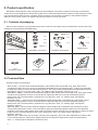
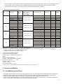
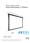
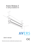
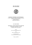
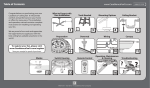
Electric projection screen Avers Contour (models above 2,4m fabrics width) User’s manual Read these instructions carefully before operating the screen. Dear Customer, Thank you very much for the purchase of our product. The manual booklet contains all operation information you may require to install properly and operate the screen. We hope it will help you to get the most performance and enjoyment of yournew screen. Enjoytime with the AversScreens product. SAFETY INFORMATION NOTICE: Important safety information. Follow the instructions described in the operating manual for safety reasons. After reading the manual, please store it in a safe place just in case you need it in the future. NOTICE: THE DEVICE HAVE TO BE EARTHED. WARNING: 1) Disconnect the device from the power supply if it will not be used within longer period of time. 2) Do not open the casing of the device in order to avoid possible electric shock. There are not any user operated parts inside the case of the screen. All service work can be done by Avers Authorized Service Center personnel only. 3) Do not remove the Ground pin from the power outlet neither connect the device to the socket without the Ground pin. If you can't put the plug to the power outlet, please ask electrician for assistance. Table of contents: 1. Safety rules 1.1. Declaration of Conformity CE 2. Product specification 2.1. Contents of package 2.2. Technical data 3. Screen installation 3.1. Installation directions 3.2. Screen installation at segmented recessed ceiling 3.3. Screen installation at cardboard-plaster recessed ceiling 3.4. Electric installation 3.5. Programming 4. Screen operation 4.1. Manual operation 4.2. Screen maintenance 4.3. Before asking for service 5. Warranty conditions 2 1. SAFETY RULES SAFETY INFORMATION NOTICE: Important safety information. It is important for the safety of persons to follow these instructions. After reading the manual, please save it just in case of need in the future Do not allow children to play with the fixed controls (remote control). Keep the remote control unit out of reach of children. Frequently examine the screen installation for imbalance and signs of wear or damage to cables. Do not use if repair or adjustment is necessary. Watch the moving screen and keep the people away until the screen is completely rolled in/out. It will help to avoid injuries caused with moving screen. Do not attach any objects to the screen’s bottom bar. Screen damage and/or person injury danger. All installation work should be carried out by the qualified technician. Improper installation of the screen can cause device damage or health breakdown. Ceiling/wall installation can be done with the originally supplied mounting brackets dedicated for this model only. Do not do anything that may damage the power cable or power plug. Do not damage the power cable: make any modifications by your own, put it near the hot objects, bend it strongly, twist it, pull out the power cable, put the heavy objects on the cable, wrap it into the bundle. Operation of the screen with damaged power cord can result with electric shock, electric short circuit and fire. Do not touch the power cable and the power plug with wet hands. Always follow the instructions described in the operating manual. 1.1. Declaration of Conformity CE Manufacturer’s Declaration of ConformityCE AVERS Screens Sp. z o.o. Under it’s own responsibility declares: All screensand accessories mentioned below are manufactured in Poland according to the essential safety requirements of Council Directive 98/79/WE Projection screens: Stratus 2, Stratus 2 Tension, Akustratus 2, Akustratus 2 Tension, Cumulus X, Cumulus X Tension, Solar, Solaris, Contour, Contour Tension, Cirrus X, Cirrus X Crank, Nimbus Projector mount brackets: Alumount, Promount, SimpleMount, Shortmount, Simlift The above mentioned products are in conformity with the European Directives and especially with the norms: PN-EN 55014-1:2007(U) PN-EN 50082-1:1997 PN-EN 60335-1:2004 PN-EN 61000-3-2:2007 PN-EN 61000-3-3:1997 IEC 60335-2-97:2007 Paweł Zieliński Pruszków 2014.07.01 3 2. Product specification Electrically rolled projection screen designed for fixed installation at projection systems for business presentations and/or home cinema applications. Best picture quality can be reached based when the selection of the projection surface type and size will be optimal for the, projection device (projector) and projection conditions at the planed installation. Optional remote control system can significantly improve comfort of use of the screen. 2.1. Contents of packaging Please check carefully if any physical damage of the screen has not happen during transportation. Please inspect the package for all accessories presented below: M8 x 12 M6x25 x 8 x8 x4 x2 x4 x 14*) x8 x8 M10 x 4 Fitting springs Complete screen x 1 Installation accessories Installation accessories x 22*) Handling magnets Wall switch x 1 Regulation wrench x 1 Operation manual x 1 *) quantity depends on the screen width: 270cm - 22pcs.; 300cm - 24pcs.; 350cm - 26pcs.; 400cm - 30pcs. 2.2 Technical Data Projection fabrics characteristics: - Silver P (SP) – a special screen dedicated fiberglass fabric double side covered with vinyl, black back surface and white front side. The front surface is coated with dedicated silver color reflecting layer . Fabrics recommended for application with DLP and LCD multimedia projectors. The narrow viewing angle determines dedicated location of the audience area in front of the screen. Gain: 2.9, viewing angle: 80 degrees, thickness: 0,7 mm. - Matt White P (MWP) – a special screen dedicated fibeglass fabric double side covered with vinyl, black back surface and white front (projection) surface, recommended for application with DLP and LCD multimedia projectors. Neutral color of the surface enables projection from any directions. Gain: 1.0, viewing angle: 150 degrees, thickness: 0,7 mm. - Matt White (MW) – a special screen dedicated fibeglass fabric double side covered with vinyl, black back surface and white front (projection) surface, recommended for application with DLP and LCD multimedia projectors. Neutral color of the surface enables projection from any directions. Gain: 1.0, viewing angle: 150 degrees, thickness: 0,35 mm. - Matt Grey (MG) – a special screen dedicated fibeglass fabric double side covered with vinyl, black back surface and grey front (projection) surface, recommended for application with high brightness DLP and LCD multimedia projectors. The surface offers deeper level of black and more realistic rich dark colors recognized as a feeling of higher image contrast. Recommended for home cinema applications. Gain: 0,8. viewing angle: 150 degrees, thickness: 0,35 mm. - White Ice (WI) – White color vinyl monofoil, matt front size (projection), gloss rear side, dedicated for projection with LCD and DLP projectors. Fabrics with slightly directional characteristics dedicated for business presentations. Gain 1,2 , viewing angle 120 degrees, thickness 0,4mm. 4 - New Coral (NC) – Rear projection white vinyl monofoil, gloss front side (projection), matt rear side, dedicated for rear projection with LCD and DLP projectors. Recommended for business presentations due to directional optical characteristics of the fabrics. Gain 3,2 , viewing angle 90 degrees, thickness 0,6mm. Dimensions of projection screens. Screen width Viewing area size [cm] [cm] Screen aspect ratio Screen case size W x H x D [cm] Projection fabrics max. length [cm] Top belt width [cm] Version *) Net weigth**) ceiling modul masking modul 260 x 146 16:9 181 35 BT 52 260 x 195 4:3 205 8 BB 52 290,5 x 15 x 14,1 260 x 146 16:9 156 8 BB 52 270 270 x 152 16:9 179 52 294,8 x 24 x 0,5 270 x 202 4:3 202 52 270 x 270 1:1 270 52 290 x 163 16:9 208 35 BT 290 x 181 4:3 236 8 BB 320,5 x 15 x 14,1 290 x 163 16:9 114 8 BB 300 300 x 169 16:9 179 324,8 x 24 x 0,5 300 x 225 4:3 235 300 x 300 1:1 310 340 x 191 16:9 236 35 BT 340 x 255 4:3 268 8 BB 370,5 x 15 x 14,1 340 x 191 16:9 208 8 BB 350 350 x 197 16:9 207 375,5 x 24 x 0,5 350 x 263 4:3 273 350 x 350 1:1 360 390 x 219 16:9 264 35 BT 390 x 244 4:3 257 8 BB 420,5 x 15 x 14,1 390 x 219 16:9 232 8 BB 400 400 x 225 16:9 235 425,5 x 24 x 0,5 400 x 300 4:3 310 400 x 400 1:1 410 ***) *) BT and BB versions are available with MWP, MW, MG and WI fabrics Version BB – 5 cm width black border surrounding the viewing area Version BT – 5 cm width black border surrounding the viewing area and additional black top 30 cm above the top black border. **) approximate value for the screen with Matt White fabrics ***) available for the screens up to 230cm height RF remote transmitter(optional): Dimensions: 110 x 58 x 20 mm Power supply: 1 x battery 12V type 23A Motor: Electric tubular engine AC: Voltage: 220-240V AC 50 Hz, 292 W Power consumption: 1,29A Rotation speed: 16 rot./min Torque: 10 Nm max. operation time:*) 4 min *) Engine single cycle operation time, operation cycle can be repeated in 20 minutes intervals. 3. Screen installation 3.1. Installation precautions - Installation work should be carried out by a qualified technician in accordance with the instructions described below. - Fixed installation of the screen should be done with use of the screws and anchors suitable for the walls/ceilings materials at the installation place and the genuine installation brackets delivered with the screen. - Check carefully after installation if the screen is perfectly leveled. Do not roll out the screen not installed in horizontal position. In case the screen leveling is not perfect correct the installation. 5 3.2. Screen installation at segmented recessed ceiling - Prepare 2 steel rifled rods M8 diameter, cut them to the length equal of the distance between the recessed ceiling and construction ceiling increased of 23 cm (rods are not included in the screen set and must be purchased separately) . - Point the location of screen ceiling anchors and drill wholes diameter ø12mm and 16,5cm depth. - Fix the ceiling anchors in the drilled wholes replacing the original anchor bolts with prepared steel rods M8 diameter.- Fix the installation brackets at the anchored steel rods. Distance between the construction ceilin and the bracke should be 5 cm shorter than distance between the construction ceiling and the recessed ceiling. - Fix the ceilin module to the brackets with supplied installation nuts. - Check leveling of the modul. Finetune leveling if needed. Secure bottom nuts with additional counter nut when the regulation is finished. Contour 27xxx 30xxx 35xxx 40xxx D[mm] 2948 3248 3748 4248 d[mm] 191 191 191 191 Pic.1 Installation of the rods and anchors in the ceiling Pic.3 Screen module installatiuon Pic.2 Ceiling modul installation Pic.4 Masking module installation - Modify the recessed ceiling checkerwork to create rectangular whole of 106 x W+191 mm dimensions, (W - screen fabrics width in milimeters). Bottom flange of the properly installed ceiling module should be surfaced with the ceiling checkerwork. - Connect the screen module to the electric installation (see chapter 3.4) - Fix the screen module inside the ceiling module. Use spiral installation springs and nuts. Check the screen module leveling, perform regulation if needed. Secure the screen module fixing nuts with counter nuts. - Arrange the handling magnets at the ceiling module bottom flange. leave distance of 30 cm between magnets. - Fix the masking module safety ropes. - Fix the masking module to the ceiling module. The masking module is installed properly when the screen bottom bar remains located centrally in the module whole and it can move down without any interruption. Masking module installation must be done by at least 3 person. The module must be supported in the middle of it’s length as well as at the middle of the distance between the module ends and the module middle point to avoid module damage. 6 Check the screen module leveling before first unrolling the screen. Do not use the screen if it is not properly. 3.3. Screen installation in the cardboard-plaster recessed ceiling. - Trace the shape of the ceiling module installation whole. Cut out the whole in the recessed ceiling according to the traced shape. - Slot up the ceiling module into the prepared whole and fix it with the installation springs. Contour 27xxx 30xxx 35xxx 40xxx D[mm] 2905 3205 3705 4205 Pic.5 Ceiling module installation slot preparation Pic.7 Screen module installation Pic.6 Ceiling module installation Pic.8 Masking module installation - Connect the screen module to the electric installation (see chapter 3.4) - Fix the screen module inside the ceiling module. Use spiral installation springs and nuts. Check the screen module leveling, perform regulation if needed. Secure the screen module fixing nuts with counter nuts. - Arrange the handling magnets at the ceiling module bottom flange. leave distance of 30 cm between magnets. - Fix the masking module safety ropes. - Fix the masking module to the ceiling module. The masking module is installed properly when the screen bottom bar remains located centrally in the module whole and it can move down without any interruption. Masking module installation must be done by at least 3 person. The module must be supported in the middle of it’s length as well as at the middle of the distance between the module ends and the module middle point to avoid module damage. Check the screen module leveling before first unrolling the screen. Do not use the screen if it is not properly. 7 3.4. Electric installation. ATTENTION: Electric installation work should be carried out by a certified electrician. - Lead out the power cables to the place of installation of the wall switch and between wall switch and screen. - Screen power line should be fused with 1A fuse. - Switch off the screen power line during installation work. - Manual wall steering switch should be installed at the place meeting the following conditions: a) installation150-180 cm above the floor level, b) the screen should be visible by the wall switch operator during the screen operation, c) wall switch operator cannot stay in reach of any of the screen’s moving parts during the screen operation . d) the wall switch must be visible from the each part of the room irrespective of the screen position. gy bl Screen bl - blue (common) br - brown (rolling up) yg - yellow-green (protective) bk - black (rolling down) Power line L1 - brown (live) N - blue (neutral) G - yellow-green (protective) br bk ~ Picture 9 Screen without remote control system electric installation Picture 10 Lower bar fine tuning 3.5. Screen programming. The screen is programmed properly at the factory and there is no need to reprogram it without any important reason. Setting of screen extreme positions was made by manufacturer. If you need to change the screen extreme position follow the instructions described below. Programing the length of the rolled out screen (screen bottom bar position). - Roll up the screen until it will stop automatically in the upper position. - part Insert included in the screen set into the regulation slot (see picture. 6) located in the left bottom ofregulation the screenwrench . Regulation knob “2” (located closer to the back of the screen) enables setting of the lower extreme position of the screen bottom bar: „+” - means increasing the lenght of the fabrics is rolled down when the screen is rolled out, „–” - means decreasing the length of the fabrics is rolled down when the screen is rolled out. Regulation knob “1” (located closer to the front of the screen) enables setting of the upper extreme position of the screen bottom bar: “-“ - means increasing the lenght of the fabrics is rolled down when the screen is rolled in, “+” - means decreasing the length of the fabrics is rolled down when the screen is rolled in IMPORTANT! Do not decrease (tuning knob 1+) the range of the rolled down surface. It can damage the screen. Do not increase (regulation 2+) the range of the surface which was rolled down behind the STOP mark, placed in the upper right corner of the screen. Rolling down the screen behind the mark can damage the screen. 8 4. Screen operation Projection screen AVERS can be operated automatically (after installation of optional remote control system) or manually. The screen should be rolled out short time before the planned projection in order to let the fabrics surface to stabilize and rolled in after projection end. Leaving the screen rolled out completely or partially for a long period of time would cause the permanent projections surface damages and/or deteriorations. 4.1. Manual operation Manual screen operation is possible with the wall control switch or by radio frequency transmitter of the optional remote control system. - Push button „€ ”, the screen will begin to roll down and stop automatically at the bottom position after rolling down. - Push button „STOP” at the remote transmitter or stop pushing the buttons „€ ” „ ” ,to stop the screen operation. - Push button „ ”, the screen will begin to roll up and stop automatically in the upper position after rolling up. 4.2. Screen maintenence Pojection screen Avers do not require periodical service maintenance. Clean dust from the screen case and fabrics with dry soft cloths. If needed use moisturized cloth with soft detergent to remove stains. After stain removal dry the cleaned surface with cloth carefully. 4.3. Before calling the service Symptoms Reasons Remedy The screen fabrics does not roll down Power failure Check the screen’s circuit fuse and the power cable the screen fabrics does not roll down smoothly The screen was not installed properly in horizontal position. Check if the screen case is properly leveled. Reinstall the screen correctly. The screen stops in the middle position. There are some objects on the bottom bar way. Remove the objects which can block the proper work of the screen or are at the bottom bar way. Power failure Check the propriety of electric installation and the state of the power wires. At other cases please contact service. 5. Warranty conditions 1) Avers screens warranty period is 24 months from the date of purchase confirmed with the original purchase invoice. 2) Extended warranty period for electric engine is 60 month. 3) Surety commits to fix free of charge any failures (component or production defects) of the product which appear during warranty period. 4) Warranty exclusions : a) the failures caused by the usage of the screen against the rules described in operation manual, b) the failures caused by improper storage or transportation, c) mechanical defects of the screen other than mentioned at point 3), d) damages caused with overvoltage at power network, e) deinstallation and reinstallation of the screen. 5) Avers Screens Service department will remove all defects within 21 days after receiving the demaged product. 6) Warranty claims should be passed to the screen supplier (dealer). 9 Manufactured after 13.08.2005 This symbol on the products and/or accompanying documents means that used electrical and electronic products should not be mixed with general household waste. Disposing of this product correctly will help to save valuable resources and prevent any potentialnegative effects on human health and the environment which could otherwise arise from inappropriate waste handling. Please contact your local authority for further details of your nearest designated collection point. Wersja 19.01.2015