1
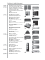
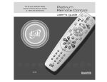
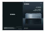
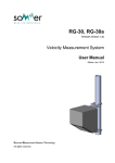
AB
Integrated Amplifier
OWNER’S MANUAL
© 2013 Yamaha Corporation
Printed in Malaysia ZG15720
A Living Tradition in Sound
A piano comes into this world through the perfect synergy of advanced technical
skill and artistry. Such a piano can create sound that truly reflects the player’s
feelings.
The final stage in piano production is called “voicing”. It is here that the
instrument is given its soul.
A highly skilled expert concentrates his mind and sensitivity on the sound of each
key, finely adjusting the dynamic feel of the hammers, bringing the tone and
vibrancy of all 88 keys together perfectly; a truly stunning achievement.
It is a quality of sound that can only be determined by an astute, sensitive ear. We
apply this very same concept to the manufacture of our audio products. The
technician performs exhaustive listening tests and every component is considered,
in order to finally achieve the ideal sound.
Yamaha’s tradition of audio quality stretches back over 125 years, and continues to
live on in all Yamaha products today.
Excellence in Audio Achievement
First HiFi System introduced in 1920
We introduced numerous HiFi components
(turntables, FM/AM tuners, integrated
amplifiers, preamplifiers, power amplifiers
and speakers) in 1955 - 1965.
Natural Sound Speaker Series introduced
in 1967
NS-20 Monitor Speaker
CA-1000 Integrated Amplifier
Featuring A-Class operation, the CA-1000 set
the standard for integrated amplifiers.
NS-690 Natural Sound Speaker
NS-1000M Monitor Speaker
A truly legendary speaker still revered by HiFi
enthusiasts.
B-1 Power Amplifier
An innovative power amp that used vertical FETs in all
stages.
C-2 Control Amplifier
Received top prize at the Milan International Music
and HiFi Show.
NS-10M Studio Monitor Speaker
Became of the most popular studio monitors
in the world.
A-1 Integrated Amplifier
PX-2 Turntable
Yamaha’s first straight arm turntable.
B-6 Power Amplifier
Pyramid-shaped power amplifier.
GT-2000/L Turntable
First CD Player (CD-1) introduced in 1983
B-2x Power Amplifier
MX-10000 Power Amplifier and
CX-10000 Control Amplifier
Redefined the capabilities of separate components.
AX-1 Integrated Amplifier
GT-CD1 CD Player
MX-1 Power Amplifier and
CX-1 Preamplifier
Soavo-1 and Soavo-2 Natural Sound
Speaker Systems
A-S2000 Stereo Amplifier and
CD-S2000 Super Audio CD Player
NP-S2000 Network Player
◆ Full floating and balanced circuit design achieves the full potential of
analogue amplification
An entirely new floating and balanced power amplifier achieves complete symmetry and permits full balanced
transmission (amplification) from the input jack to just before the speaker jack.
◆ Full-stage balanced signal transmission
The integrated amplifier offers full stage balanced transmission, combining high power output with good sound texture
and outstanding S/N performance.
◆ Parallel volume and tone control
◆ Large power supply with four separate circuits
◆ Left-right symmetrical design with rigid, stable construction
◆ Discrete phono amplifier
◆ High-quality headphone amplifier with low-impedance drive
■ Supplied accessories
Please check that you have received all of the following parts.
• Remote control
• Batteries (AAA, R03, UM-4) (×2)
• Power cable
• SAFETY BROCHURE
Contents
Controls and functions.......................................................................................................................................... 6
Connections.......................................................................................................................................................... 16
Specifications. ...................................................................................................................................................... 24
Troubleshooting................................................................................................................................................... 28
■ About this manual
• y indicates a tip for your operation.
• The color of images in this manual may vary from the original.
• Read the “SAFETY BROCHURE” before using this unit.
4 En
Controls and functions
In this chapter, you will learn the controls and functions of A-S3000.
5 En
Controls and functions
■ Front panel (pages 6 to 9)
LEFT
– 60
40
30
0.01
0.1
20
RIGHT
10
3
1 10 50
3 +
0
– 60
40
100
30
0.01
0.1
dB
PHONES
-6
TRIM
SPEAKERS
0
A
+6
OFF
B
3
1 10 50
TREBLE
3 +
0
100
INPUT
BALANCE
BAL 2
METER
OFF PEAK VU
BAL 1
CD
LINE 1
A+B
BI-WIRING
+12
10
dB
BASS
STANDBY/ON
20
LINE 2
–
1
2 3
4
5
6
1 STANDBY/ON/OFF switch
Turns on or off this unit.
STANDBY/ON (upper position):
In this position, you can select STANDBY or ON,
using the p AMP key on the remote control.
OFF (lower position):
The power of this unit is turned off.
Notes
• When you turn on this unit, it will take a few seconds
before this unit can reproduce sound.
• If you disconnect the power cable from the AC outlet and
connect it again when this unit is in STANDBY mode, the
power of the unit is turned on. If the unit is not to be
operated for a long time, set the STANDBY/ON/OFF
switch to OFF.
2 STANDBY/ON indicator
Lit brightly:
Shows that the power of the unit is ON. In this
condition, you can switch the unit to STANDBY mode
using the p AMP key on the remote control.
Lit dimly:
Shows that the unit is in STANDBY mode. In this
condition, press the p AMP key on the remote control
to turn on the unit.
6 En
7
+
8
–
+
9
L
R
:
Off:
Shows that the power of the unit is OFF. In this
condition, you can turn on the unit using the
STANDBY/ON/OFF switch only.
3 PHONES jack
Outputs audio for private listening with headphones.
Notes
• When headphones are plugged in:
– Both speaker sets connected to the SPEAKERS L/R CH
terminals are turned off.
– No signals are output at the PRE OUT jacks.
– You cannot select MAIN DIRECT as the input source.
• If headphones are plugged into the PHONES jack while
MAIN DIRECT is selected as the input source, no audio is
output at the PHONES jack.
4 TRIM selector
Adjusts the volume level when headphones are
plugged in to avoid sudden changes in volume.
Choices: –6 dB, 0 dB, +6 dB, +12 dB
PHON
MM
PHONO
MAIN DIRECT
dB
OFF
TUNER
MC
VOLUME
3
0
3 +
0
100
INPUT
BAL 1
CD
PHONO
MM
TUNER
AUDIO MUTE
PHONO
MC
6 METER selector
Switches the display of the meter to OFF, PEAK or
VU.
OFF:
Turns off the meter and the illumination.
PEAK:
Switches the meter to a peak level meter. The peak
level meter shows a momentarily highest audio output
level.
VU:
Switches the meter to a VU (Volume Unit) level meter.
The VU level meter shows an effective audio output
value that is similar to human senses.
7 Meter displays (LEFT/RIGHT)
Show the audio output level of the left (LEFT) and
right (RIGHT) channels in VU or PEAK meter mode.
The VU or PEAK meter can be selected by the
METER selector.
8 BASS control
Increases or decreases the low frequency response.
The 0 position produces a flat response.
Control range: –10 dB to +10 dB
5 SPEAKERS selector
Turns on or off the speaker set connected to the
SPEAKERS L/R CH A and/or B terminals on the rear
panel.
• Switch to the OFF position to turn off both speaker
sets.
• Switch to the A or B position to turn on the speaker
set connected to the SPEAKERS L/R CH A or B
terminals.
• Switch to the A+B BI-WIRING position to turn on
both speaker sets.
Caution
9 TREBLE control
Increases or decreases the high frequency response.
The 0 position produces a flat response.
Control range: –10 dB to +10 dB
0 BALANCE control
Adjusts the audio output balance of the left and right
speakers to compensate for sound imbalances caused
by speaker locations or listening room conditions.
Notes
• When both the BASS and TREBLE controls are set to the 0
position, audio signal bypasses the tone control circuitry.
• The BASS, TREBLE and BALANCE controls do not affect the
signals input at the MAIN IN jacks and signals output at the
LINE 2 REC jacks.
If you use two sets (A and B), the impedance of each speaker
must be 8 Ω or higher.
7 En
Controls and functions
■ Front panel (pages 6 to 9)
RIGHT
LEFT
– 60
40
30
0.01
0.1
20
10
3
1 10 50
3 +
0
– 60
40
100
30
0.01
0.1
dB
PHONES
TRIM
-6
0
SPEAKERS
+6
OFF
+12
A
TREBLE
3
0
INPUT
BAL 2
BAL 1
LINE 1
A+B
BI-WIRING
TUNER
LINE 2
–
+
–
+
L
A
A Remote control sensor
Receives signals from the remote control.
y
The remote control transmits a directional infrared beam. Be
sure to aim the remote control directly at the remote control
sensor on the front panel of this unit during operation.
30
30
CD
Approximately 6 m (20 ft)
MC
R
B
B INPUT selector/indicator
Selects the input source to be played back. The
indicator of the input source selected with the INPUT
selector lights.
The audio signals of the selected input source are also
output at the LINE 2 REC jacks.
MAIN DIRECT: Selects the component connected to
the MAIN IN jacks.
When MAIN DIRECT is selected as the input
source, the audio signals are not output at the PRE
OUT, LINE 2 REC and PHONES jacks.
LINE 1/LINE 2: Selects the component connected to
the LINE 1 or LINE 2 jacks.
BAL 1/BAL 2: Selects the component connected to
the BAL 1 or BAL 2 jacks (balanced XLR jacks).
CD: Selects the CD player connected to the CD jacks
(unbalanced RCA jacks).
TUNER: Selects the tuner connected to the TUNER
jacks.
PHONO: Selects the turntable connected to the
PHONO jacks.
Note
When LINE 2 is selected, the audio signals are not output at
the LINE 2 REC jacks.
8 En
PHONO
MM
PHONO
MAIN DIRECT
dB
OFF
3 +
100
BALANCE
METER
OFF PEAK VU
B
10
1 10 50
dB
BASS
STANDBY/ON
20
E AUDIO MUTE indicator
Lights when the mute function is turned on with the
AUDIO MUTE switch.
F VOLUME control
Controls the volume level. This does not affect the
output level at the LINE 2 REC jacks.
VOLUME
Note
3
0
3 +
The VOLUME control does not affect when you select
MAIN DIRECT as the input source. Adjust the volume level
using the volume control on the external amplifier connected
to the MAIN IN jacks.
100
PHONO
MM
AUDIO MUTE
MC
C
D
E
F
C PHONO switch
Selects the type of magnetic cartridge of the turntable
connected to the PHONO jacks on the rear panel.
• Press upward to the MM position when the
connected turntable has a moving magnet (MM)
cartridge.
• Press downward to the MC position when the
connected turntable has a moving coil (MC)
cartridge.
y
When you replace the cartridge, be sure to turn off this unit.
D AUDIO MUTE switch
Press downward to reduce the current volume level by
approximately 20 dB. Press again to restore the audio
output to the previous volume level.
y
You can also rotate the VOLUME control on the front panel
or press the VOLUME + or – key on the remote control to
resume the audio output.
9 En
Controls and functions
■ Rear panel
1
3
2
4
5
6
AUTO POWER STANDBY
GND
PHONO
ON
BAL 1
TUNER
OFF
BAL 2
LINE 1
CD
NORMAL(EIA)
SPEAKERS R CH
ATTENUATOR
BYPASS
ATT.
(-6DB)
PHASE
NORMAL
INV.
ATTENUATOR
BYPASS
ATT.
(-6DB)
PHASE
NORMAL
INV.
+HOT
2
1
3
- COLD
SYSTEM CONNECTOR
REMOTE
IN
OUT
TRIGGER
IN
AC IN
D
E
A OR B:4 MIN./SPEAKER A + B:8 MIN./SPEAKER
A
B
C
3 PHONO input jacks
6 AUTO POWER STANDBY switch
ON:
The unit enters STANDBY mode automatically if not
operated for 8 hours.
OFF:
The unit does not enter STANDBY mode
automatically.
4 CD input jacks
7 LINE 1 input jacks
5 BAL 1/BAL 2 (balanced) input jacks
Two sets of balanced input jacks are provided.
Set the ATTENUATOR selector and PHASE selector
associated with the BAL 1 or BAL 2 jacks according
to the player connected to the corresponding jacks.
For details of settings, see page 20.
8 LINE 2 jacks
PB (playback) input jacks and REC (recording) output
jacks are provided.
See page 16 for connection information.
1 TUNER input jacks
2 GND (Ground) terminal
10 En
G
A SPEAKERS L/R CH terminals
7
8
9
0
AUTO POWER STANDBY
ON
OFF
LINE 2
LINE 1
REC
PRE OUT
MAIN IN
PB
NORMAL(EIA)
SPEAKERS L CH
ASE
INV.
+HOT
2
1
GND
B SYSTEM CONNECTOR
Use this connector to connect a product testing device
for servicing.
C REMOTE IN/OUT jacks
Use these jacks to connect an external component for
remote control.
For details on the connection, see page 21.
D TRIGGER IN jack
Use this jack to connect an external component for the
trigger function.
For details on the connection, see page 22.
3
E AC IN inlet
Use this inlet to plug in the supplied power cable.
For details on the connection, see page 19.
- COLD
A OR B:4 MIN./SPEAKER A + B:8 MIN./SPEAKER
A
F Foot
The feet of this unit include built-in spikes. Using the
spikes can reduce the effect of vibrations on the set.
When using the spikes, remove the transport tape, then
remove the magnet foot by pulling it.
F
Spike
9 PRE OUT jacks
y
• The PRE OUT jacks output the same channel signal as the
SPEAKERS L/R CH terminals.
• When you connect a stereo cable to the PRE OUT jacks to
drive the speakers using an external amplifier, it is not
necessary to use the SPEAKERS L/R CH terminals.
• The signal output at the PRE OUT jacks are affected by the
BASS and TREBLE control settings.
0 MAIN IN jacks
Use these jacks to connect an external component
equipped with a volume control.
Note
Transport
tape
Magnet
foot
Caution
When using the feet’s built-in spikes, the spikes may scratch
the shelf or floor on which this unit is installed. Use the
magnet feet or appropriate supports when placing this unit on
expensive furniture, etc.
y
If this unit is unstable, you can adjust the foot height by
rotating it.
When you select MAIN DIRECT as the input source, the
volume level is fixed.
Adjust the volume level using the volume control on the
external amplifier connected to the MAIN IN jacks when you
select MAIN DIRECT as the input source.
For the connection to the MAIN IN jacks, see pages 16 and
17.
11 En
Controls and functions
■ Remote control
1
1 Infrared signal transmitter
Outputs infrared control signals.
2
2 p AMP key
Turns this unit ON or switches it to STANDBY mode.
For details on STANDBY mode, see “Front panel”
(page 6).
AMP OPEN/CLOSE
1
CD
2
5
6
BAL
1
3
2
LINE
PHONO
MAIN DIRECT
CD
TUNER
When LINE 2 is selected as the input source, the audio
signals are not output at the LINE 2 REC jacks.
BAND
4
PRESET
7
SOURCE
LAYER
VOLUME
BAL: Selects the component connected to the BAL 1
or BAL 2 jacks (balanced XLR jacks).
LINE: Selects the component connected to the
LINE 1 or LINE 2 jacks.
PHONO: Selects the turntable connected to the
PHONO jacks.
MAIN DIRECT: Selects the component connected to
the MAIN IN jacks. When MAIN DIRECT is
selected as the input source, the audio signals are
not output at the PRE OUT, LINE 2 REC and
PHONES jacks.
CD: Selects the CD player connected to the CD jacks
(unbalanced RCA jacks).
TUNER: Selects the tuner connected to the TUNER
jacks
4 Yamaha tuner control buttons
Control functions of Yamaha tuner. Refer to the
owner’s manual of your tuner for details.
8
MUTE
9
12 En
3 Input select keys
Selects the input source to be played back.
The audio signals of the selected input source are
output at the LINE 2 REC jacks.
y
Note
Some Yamaha tuners cannot be controlled by this remote
control.
5 p CD key
Turns the Yamaha CD player ON or switches it to
STANDBY mode.
8 VOLUME +/– keys
Control the volume level.
Note
6
OPEN/CLOSE key
Opens/closes the disc tray of the Yamaha CD player.
Refer to the owner’s manual of your CD player for
details.
Note
Some Yamaha CD players do not support the CD key and/or
OPEN/CLOSE key of this remote control.
The VOLUME keys do not affect when you select MAIN
DIRECT as the input source. Adjust the volume level on the
external amplifier connected to the MAIN IN jacks.
9 MUTE key
Reduces the current volume level by approximately
20 dB. Press again to restore the audio output to the
previous volume level. Pressing the VOLUME + or key also cancels muting.
7 Yamaha CD player control keys
Control various functions of Yamaha CD player. Refer
to the owner’s manual of your CD player for details.
(Play)
Starts playback.
(Pause)
Pauses playback. Press the
playback.
or
to resume
(Stop)
Stops playback.
/
(Skip)
Skips to the next track, or skips back to the beginning
of the current track.
SOURCE
Selects the source to be played on the Yamaha CD
player. The playback source changes each time this
key is pressed.
LAYER
Switches the playback layer of a hybrid SA-CD
between SA-CD and CD.
13 En
Controls and functions
■ Installing batteries in the remote control
1
Remove the battery compartment cover.
2
Insert the two batteries (AAA, R03, UM-4)
according to the polarity markings (+ and -)
on the inside of the battery compartment.
1
2
3
Reinstall the battery compartment cover.
3
14 En
Connections
In this section, you will make connections between A-S3000, speakers,
and source components.
Connections
Turntable
Speakers A
(R channel)
Ground
+
-
AUTO POWER STANDBY
GND
PHONO
ON
TUNER
OFF
BAL 2
BAL 1
LINE
CD
NORMAL
SPEAKERS R CH
ATTENUATOR
BYPASS
ATT.
(-6dB)
PHASE
NORMAL
INV.
ATTENUATOR
BYPASS
ATT.
(-6dB)
PHASE
NORMAL
INV.
+HOT
2
1
3
- COL
SYSTEM CONNECTOR
REMOTE
IN
OUT
TRIGGER
IN
AC IN
A OR B:4 MIN./SPEAKER A + B:8 MIN./SPEAKER
+
-
Speakers B
(R channel)
Tuner
CD player with
RCA jacks
CD player with
XLR jacks
Caution
• Do not let the bare speaker wires touch each other or do not let
them touch any metal part of this unit. This could damage this
unit and/or the speakers.
• All connections must be correct: L (left) to L, R (right) to R,
“+” to “+”, and “–” to “–”. If the connections are faulty, no
sound will be heard from the speakers, and if the polarity of the
speaker connections is incorrect, the sound will be unnatural
and lack bass. Also, refer to the owner’s manual for each of
your components.
16 En
• Use RCA unbalanced cables to connect other components
except speakers. Use XLR balanced cables to connect a CD
player or network player with XLR balanced output jacks to the
BAL 1 or BAL 2 jacks of this unit.
• Connect your turntable to the GND terminal to reduce noise in
the signal. However, you may hear less noise without the
connection to the GND terminal for some turntables.
Preamplifier,
AV receiver, etc.
CD recorder,
tape deck, etc.
External amplifier or
active subwoofer
Speakers A
(L channel)
-
+
AUTO POWER STANDBY
ON
BAL 1
OFF
BAL 2
LINE 2
LINE 1
REC
PRE OUT
MAIN IN
PB
NORMAL(EIA)
ATOR
ATT.
(-6DB)
PHASE
NORMAL
INV.
ATTENUATOR
BYPASS
ATT.
(-6dB)
SPEAKERS L CH
PHASE
NORMAL
INV.
+HOT
2
1
GND
3
- COLD
AC IN
A OR B:4 MIN./SPEAKER A + B:8 MIN./SPEAKER
–
Network player with
XLR jacks
+
Speakers B
(L channel)
BD player, etc.
Caution
Fig. 1
+
L
Fig. 2
+
L
–
–
–
–
R
R
+
• Because the power amplifier of A-S3000 is of the floating balanced type, the
following types of connections are not possible.
– Connecting with the left channel “–” terminal and the right channel “–” terminal
as well as “+” terminals (Fig. 1).
– Connecting with the left channel “–” terminal and the right channel “–” terminal
inverted (cross connection, Fig. 2).
– Deliberately connecting with the left/right channel “–” terminals and metal part
on the rear panel of this unit, as well as accidentally touching them.
• Do not connect your active subwoofer to the SPEAKERS L/R CH terminal.
Connect it to the PRE OUT jacks of this unit.
• Do not connect a component with no volume control, such as a CD player, to the
MAIN IN jacks, as the volume level of the signals input to the MAIN IN jacks is
fixed. If such equipment is connected, a sound may burst, and the unit and/or
speaker may be damaged.
+
GER
17 En
Connections
■ Connecting the speakers
■ Connecting the banana plug
(Except for Europe models)
1
Remove approximately 10 mm of insulation
from the end of each speaker cable and twist
the exposed wires of the cable together to
prevent short circuits.
First, tighten the knob and then insert the banana
plug into the end of the corresponding terminal.
10 mm
Banana plug
2
Unscrew the knob and then insert the bare
wire into the hole.
Hole for banana plug:
5.5 mm dia.
■ Connecting the Y-shaped lug
1
Unscrew the knob and then sandwich the Yshaped lug between the ring part and base.
Slide
Y-shaped lug
Hole for speaker cable:
6.0 mm dia.
3
Tighten the knob.
Terminal screw for Y-shaped
lug: 5.0 mm dia.
2
Caution
• When loosening the knob of the speaker terminal, do not rotate
it excessively. The knob may come off and pose the danger of
being swallowed by a child.
• Touching the speaker terminal with a metallic rack may cause
short circuit and damage this unit. When installing the unit in a
rack, maintain a sufficient clearance to prevent the speaker
terminals from touching the rack.
• To reduce the risk of electric shock, do not touch the speaker
terminal when the unit is turned on.
18 En
Tighten the knob.
■ Bi-wire connection
■ Connecting the power cable
The bi-wire connection separates the woofer from the
combined midrange and tweeter section. A bi-wire
compatible speaker has four binding post terminals. These
two sets of terminals allow the speaker to be split into two
independent sections. This split connects the mid and high
frequency drivers to one set of terminals and the low
frequency driver to the other pair.
Plug the power cable into the AC IN inlet when all
connections are complete, and then plug in the power
cable to the AC outlet.
TTENUATOR
PASS
ATT.
(-6dB)
PHASE
NORMAL
INV.
ATTENUATOR
BYPASS
ATT.
(-6dB)
PHASE
NORMAL
INV.
Example of a bi-wiring connection (L channel)
TRIGGER
IN
AC IN
SPEAKERS L CH
Rear panel of A-S3000
A OR B:4 MIN./SPEAKER A + B:8 MIN./SPEAKER
Speaker
Rear panel of A-S3000
Caution
To use the bi-wire connections, the impedance of each speaker
must be 8 Ω or higher.
Supplied power cable
Note
Remove the shorting bars or bridges to separate the LPF (low
pass filter) and HPF (high pass filter) crossovers.
y
To use the bi-wire connections, switch the SPEAKERS selector
to the A+B BI-WIRING position.
to an AC outlet
19 En
Connections
■ Connecting to the BAL 1/BAL 2 jacks
Connect your CD player or network player with the XLR
balanced output jacks.
Set the ATTENUATOR selector and PHASE selector
located below the BAL 1 or BAL 2 jacks according to the
component to be connected.
ATTENUATOR selector:
Select the allowable input level for the XLR balanced
input jacks. If sound from the connected component is
distorted, set the ATTENUATOR selector to ATT. (-6 dB).
XLR connectors:
When connecting, be sure to match the pins and insert the
connector of the “male” XLR balanced cable until you
hear a “click”. When disconnecting, pull out the “male”
XLR balanced cable while holding down the lever of the
BAL 1 or BAL 2 jack.
“Female” XLR connector
Lever
PHASE selector:
Select the assignment of the HOT pin of the XLR
balanced input jacks (pin 2 HOT or pin 3 HOT).
BAL 1/BAL 2 jack
NORMAL (pin 2 HOT)
“Male” XLR connector
2: hot
1: ground
Note
To use the XLR balanced connection, you must select BAL 1 or
BAL 2 as the input source.
3: cold
INV. (pin 3 HOT)
2: cold
1: ground
3: hot
Refer to the owner’s manual supplied with the connected
component and verify the assignment of the HOT pin of
its XLR balanced output jacks.
y
Yamaha CD players are set to NORMAL (pin 2 HOT).
20 En
■ Operating this unit from another room
If you connect an infrared receiver and transmitter to the
REMOTE IN/OUT jacks of this unit, you can operate the
unit and/or external component using the supplied remote
control located in another room.
Infrared receiver
REMOTE
IN
OUT
When you have another Yamaha component supporting
remote connection, as this unit does, an infrared
transmitter is not necessary. You can transmit remote
signals by connecting an infrared receiver and the
REMOTE IN jack of the other component to the
REMOTE IN/OUT jacks of this unit, using cables with
monaural miniplugs.
Up to three Yamaha components (including this unit) can
be connected.
Rear panel of A-S3000
Rear panel of A-S3000
SYSTEM CONNECTOR
■ Remote connection between Yamaha
components
TRIGGER
IN
Infrared transmitter
SYSTEM CONNECTOR
REMOTE
IN
OUT
TRIGGER
IN
Infrared receiver
REMOTE
IN
OUT
Remote control
External component
(CD player, etc.)
Remote control
Yamaha component
(up to three
components
including this unit)
21 En
Connections
■ Connecting a component supporting
the trigger function such as a Yamaha
AV receiver
The operations of this unit can be controlled in
synchronization with the operations of the connected
component, such as a Yamaha AV receiver (power ON/
STANDBY or MAIN DIRECT input selection).
Connect the PRE OUT jacks and the TRIGGER OUT jack
of the Yamaha AV receiver to this unit as illustrated
below:
Rear panel of A-S3000
AUTO POWER STANDBY
GND
PHONO
ON
BAL 1
OFF
BAL 2
LINE 2
LINE 1
REC
PRE OUT
TUNER
CD
MAIN IN
PB
NORMAL(EIA)
SPEAKERS R CH
ATTENUATOR
BYPASS
ATT.
(-6DB)
PHASE
NORMAL
INV.
ATTENUATOR
BYPASS
ATT.
(-6DB)
SPEAKERS L CH
PHASE
NORMAL
INV.
+HOT
2
1
GND
3
- COLD
SYSTEM CONNECTOR
REMOTE
IN
OUT
TRIGGER
IN
AC IN
A OR B:4 MIN./SPEAKER A + B:8 MIN./SPEAKER
A OR B:4 MIN./SPEAKER A + B:8 MIN./SPEAKER
TRIGGER
IN
MAIN IN
RCA stereo cable
PRE OUT
TRIGGER
OUT
Yamaha AV receiver, etc.
with PRE OUT and
TRIGGER OUT jacks
When the power of the connected component is turned on,
this unit turns on and the input is set to MAIN DIRECT
automatically.
When MAIN DIRECT is selected as the input source, this
unit enters STANDBY mode if the power of the connected
component is turned off.
Note
To enable synchronization, turn off this unit before connecting
the component to the MAIN IN jacks. The synchronization
cannot be activated when the STANDBY/ON/OFF switch of the
unit has been set to OFF.
22 En
Specifications
In this section, you will find technical specifications for A-S3000.
Specifications
POWER SECTION
CONTROL SECTION
• Rated Output Power
(8 Ω , 20 Hz to 20 kHz, 0.07% THD) .................. 100 W + 100 W
(4 Ω , 20 Hz to 20 kHz, 0.07% THD) .................. 150 W + 150 W
• Input Sensitivity/Input Impedance
CD, etc. ........................................................... 200 mVrms/47 kΩ
PHONO MM ................................................... 2.5 mVrms/47 kΩ
PHONO MC ...................................................... 100 μVrms/50 Ω
MAIN IN ................................................................ 1 Vrms/47 kΩ
BAL 1/BAL 2 ............................................... 200 mVrms/100 kΩ
• Dynamic Power (IHF)
(8 Ω) ..................................................................... 120 W + 120 W
(6 Ω) ..................................................................... 150 W + 150 W
(4 Ω) ..................................................................... 200 W + 200 W
(2 Ω) ..................................................................... 300 W + 300 W
• Dynamic Headroom
(8 Ω) ................................................................................. 0.79 dB
• Maximum Output Power
[U.K. and Europe models only]
(1 kHz, 0.7% THD, 4 Ω)...................................... 170 W + 170 W
• Maximum Effective Output Power (JEITA)
[Taiwan, China, Korea, Asia and U.K. models only]
(1 kHz, 10% THD, 8 Ω)........................................ 130 W + 130 W
(1 kHz, 10% THD, 4 Ω)........................................ 210 W + 210 W
• Headphone Jack Rated Output Power
CD, etc. (1 kHz, 32 Ω, 0.2% THD) .................. 70 mW + 70 mW
• Channel Separation
CD, etc. (Input, 5.1 kΩ Terminated, 1 kHz/10 kHz)
...................................................................... 74/54 dB or higher
PHONO MM (Input shorted, 1 kHz/10 kHz, Vol.:−30 dB)
....................................................................... 90/77 dB or higher
PHONO MC (Input shorted, 1 kHz/10 kHz, Vol.:−30 dB)
....................................................................... 66/77 dB or higher
• Power Bandwidth
(MAIN L/R, 0.1% THD, 45 W, 8 Ω) .................. 10 Hz to 60 kHz
• Tone Control Characteristics
BASS
Boost/Cut (50 Hz) ............................................................. ±9 dB
Turnover Frequency ........................................................ 350 Hz
TREBLE
Boost/Cut (20 kHz) ........................................................... ±9 dB
Turnover Frequency ....................................................... 3.5 kHz
• Damping Factor
(1 kHz, 8 Ω) ..............................................................250 or higher
GENERAL
• IEC Output Power [U.K. and Europe models only]
(1 kHz, 0.02% THD, 8 Ω)..................................... 105 W + 105 W
• Maximum Input Signal Voltage
PHONO MM (1 kHz, 0.003% THD) ........................... 50 mVrms
PHONO MC (1 kHz, 0.003% THD) ........................... 2.3 mVrms
CD, etc. (1 kHz, 0.5% THD) ........................................ 2.80 Vrms
BAL 1/BAL 2 (1 kHz, 0.5% THD)
(BYPASS) ................................................................. 2.80 Vrms
(ATT. -6 dB) ............................................................... 5.60 Vrms
• Power Supply
[U.S.A and Canada models] ............................. AC 120 V, 60 Hz
[Taiwan model] ................................................. AC 110 V, 60 Hz
[China model] ................................................... AC 220 V, 50 Hz
[Korea model] ................................................... AC 220 V, 60 Hz
[Australia model] .............................................. AC 240 V, 50 Hz
[U.K. and Europe models] ................................ AC 230 V, 50 Hz
[Asia model] ....................................... AC 220 - 240 V, 50/60 Hz
• Rated Output Voltage/Output Impedance
REC OUT ..................................................... 200 mVrms/1.5 kΩ
PRE OUT ......................................................... 1.0 Vrms/1.5 kΩ
• Power Consumption
[U.S.A and Canada models] ............................................. 500 VA
[Other models] .................................................................... 350 W
• Frequency Response
CD, etc. (5 Hz to 100 kHz) ............................................ +0/−3 dB
CD, etc. (20 Hz to 20 kHz) ......................................... +0/−0.3 dB
• Standby Power Consumption ...................................................0.3 W
• RIAA Equalization Deviation
PHONO MM .................................................................... ±0.5 dB
PHONO MC ..................................................................... ±0.5 dB
• Total Harmonic Distortion
PHONO MM to REC OUT
(20 Hz to 20 kHz, 1.2 Vrms) ............................................ 0.005%
PHONO MC to LINE 2 REC
(20 Hz to 20 kHz, 1.2 Vrms) .............................................. 0.02%
BAL 1/BAL 2 to SPEAKERS
(20 Hz to 20 kHz, 50 W/8 Ω) ........................................... 0.025%
CD, etc. to SPEAKERS
(20 Hz to 20 kHz, 50 W/8 Ω) ........................................... 0.025%
• Signal to Noise Ratio (IHF-A Network)
PHONO MM (5 mVrms, Input shorted) ............................. 93 dB
PHONO MC (500 μVrms, Input shorted) .......................... 85 dB
CD, etc. (200 mVrms, Input shorted) ................................ 103 dB
• Residual Noise (IHF-A Network) .................................... 33 μVrms
24 En
• Dimensions (W × H × D) ................................ 435 × 180 × 464 mm
(17-1/8” × 7-1/8” × 18-1/4”)
• Weight .................................................................. 24.6 kg (54.2 lbs)
* Specifications are subject to change without notice.
■ Block diagram
BAL 1
BAL 2
HOT (+)
COLD (-)
HOT (+)
COLD (-)
Phase change
(normal / inv.)
UNBALANCE
CONVERTER
COLD (-)
HOT (+)
BALANCE
BALANCE GAIN SEL
INPUT SELECTOR
MM EQ
AMP
MC
HEAD AMP
MM//MC
FOR
MC AMP
VOLUME
ATT.UINT1
ATT.UINT2
ATT.UINT3
ATT.UINT1
ATT.UINT2
ATT.UINT3
FLAT (DEFEAT)
TONE CONTROL
FLAT (DEFEAT)
TONE CONTROL
INDEPENDENT REGULATED POWER SUPPLY (for AUDIO)
SUB TRANSFORMER
POWER RELAY
BUFFER AMP
BUFFER AMP
PRE OUT BUFFER
TOROIDAL
TRANSFORMER
Peak / VU
METER CIRCUIT
LOW IMPEDANCE DRIVE
HEADPHONE AMP.
Log amplifier
POWER AMP PRE STAGE
R CH
R CH
L CH
L CH
FLOATING POWER SUPPLY
DRIVER
FLOATING BALANCE
POWER AMPLIFIER
FLOATING BALANCE
SPEAKER DRIVER
MOSFET
FLOATING BALANCE
SPEAKER DRIVER
MOSFET
PHONO
CD
TUNER
REC OUT BUFFER
VOLUME
FOR
After Vol Amp
LINE1
PROTECTION
INPUT
FOR
MM EQ AMP
LINE2
MAIN IN
(REC)
LINE2 OUT
PRE OUT
REAR PANEL
CPU
TREBLE BALANCE
FOR
VOLUME1 (Lch)
RELAY
CONTROL
BASS
Standby power
AUDIO MUTE
FOR
VOLUME2 (Rch)
MOTOR VOL
IR IN
OFF/A/B/A+B OFF/PEAK/VU
PHONO
MM/MC
FOR
Input Amp
METER
TRIGGER IN
IR OUT
TRIM
PHONES SPEAKERS METER
FRONT PANEL
CPU/LOGIC, etc.
SP A Lch
SP B Lch
L CH
SPEAKER OUT
+
A
–
+
B
–
HEAD PHONE
METER
IR
REMOTE
METER UNIT
To POWER AMP
R CH
25 En
Specifications
■ Tone control characteristics
14
12
10
8
6
Response (dB)
4
2
0
–2
–4
–6
–8
–10
–12
–14
10
20
30
50
100
200
300
500
1k
2k
3k
5k
10k
20k 30k
Frequency (Hz)
■ Total harmonic distortion
1.000
0.500
0.200
THD + N Ratio (%)
0.100
0.050
20kHz
0.020
20Hz
0.010
0.005
1kHz
0.002
0.001
1
2
5
10
20
Output (W)
26 En
50
100
50k
100k
■ Total harmonic distortion (PHONO)
10
5
3
2
1
THD + N Ratio (%)
0.5
0.3
0.2
0.1
0.05
20Hz
0.03
0.02
1kHz
20kHz
0.01
0.005
0.003
0.002
0.001
0.0005
0.0003
0.0002
0.0001
100µ
200µ
500µ
1m
2m
5m
10m
20m
50m
100m
200m
500m
1
2
Generator Level (Vrms)
27 En
Troubleshooting
Refer to the chart below if this unit does not function properly. If the problem you are experiencing is not listed below or
if the instructions below do not help, turn off this unit, disconnect the power cable, and contact the nearest authorized
Yamaha dealer or service center.
Problem
Cause
Remedy
See
page
The power cable is not connected to the
AC IN inlet on the rear panel or not
plugged in the AC wall outlet.
Connect the power cable firmly.
The protection circuitry has been activated
because of a short circuit, etc.
Check that the speaker wires are not touching each
other or shorting out against the rear panel of this
unit, and then turn the power of this unit back on.
This unit has been exposed to a strong
external electric shock (such as lightning
or strong static electricity).
Turn off this unit, disconnect the power cable, plug it
back in after 30 seconds, and then use it normally.
The protection circuitry has been activated
because of a short circuit, etc.
Check that the speaker wires are not touching each
other or shorting out against the rear panel of this
unit, and then turn the power of this unit back on.
18
There is a problem with the internal
circuitries of this unit.
Disconnect the power cable and contact the nearest
authorized Yamaha dealer or service center.
—
The INPUT indicator
on the front panel
flashes and the
volume is turned
down when you turn
on this unit.
The protection circuitry has been activated
because of a short circuit, etc.
Check that the speaker wires are not touching each
other or shorting out against the rear panel of this
unit, and then turn the power of this unit back on.
No sound.
Incorrect input or output cable
connections.
Connect the cables properly. If the problem persists,
the cables may be defective.
16
No appropriate input source has been
selected.
Select an appropriate input source with the INPUT
selector on the front panel (or one of the input
selector keys on the remote control).
8, 12
The SPEAKERS selector is set to OFF.
Switch the SPEAKERS selector to the appropriate
position.
7
Speaker connections are not secure.
Secure the connections.
18
The sound suddenly
goes off.
The protection circuitry has been activated
because of a short circuit, etc.
Check that the speaker wires are not touching each
other or shorting out against the rear panel of this
unit, and then turn the power of this unit back on.
18
The volume level
cannot be adjusted.
MAIN DIRECT is selected as the input
source.
Adjust the volume on the connected component.
Or connect external component to input jacks other
than MAIN IN and select the corresponding input
source.
8, 9
Only the speaker on
one side can be
heard.
Incorrect cable connections.
Connect the cables properly. If the problem persists,
the cables may be defective.
16
Incorrect setting for the BALANCE
control.
Set the BALANCE control to the appropriate
position.
7
There is a lack of bass
and no ambience.
The + and – wires are connected in
reverse at the amplifier or the speakers.
Connect the speaker wires to the correct + and –
phase.
16
A “humming” sound
is heard.
Incorrect cable connections.
Connect the audio cable plugs firmly. If the problem
persists, the cables may be defective.
16
No connection from the turntable to the
GND terminal.
Connect the turntable to the GND terminal of this
unit.
16
This unit fails to turn
on.
The STANDBY/ON
indicator on the front
panel flashes.
28 En
19
18
—
18
Problem
Cause
Remedy
See
page
The sound from the
component
connected to the BAL
1/BAL 2 jacks is
degraded.
The sound level is higher than the
maximum input level for the XLR
balanced input jacks.
If the output level of the connected component is
double, set the ATTENUATOR selector located
below the input jacks to ATT. (-6 dB).
Bass is not spatial
when BAL 1/BAL 2
(balanced input) is
selected.
The polarity is incorrect.
Select the correct polarity with the PHASE selector.
The sound is
degraded when
listening with the
headphones
connected to the CD
player connected to
this unit.
The power of this unit is turned off.
The volume level is
low while playing a
record.
Incorrect setting for the PHONO switch
on the front panel.
Switch the PHONO switch to the MM or MC position
according to the type of magnetic cartridge of the
turntable.
9
The remote control
does not work or
function properly.
Wrong distance or angle.
The remote control functions within a maximum
range of 6 m (20 ft) and no more than 30 degrees offaxis from the front panel.
8
20
20
Turn on the power of this unit.
—
Direct sunlight or lighting (from an
inverter type of fluorescent lamp, etc.) is
striking the remote control sensor of this
unit.
Reposition this unit.
The batteries are weak.
Replace all batteries.
—
14
Taking care of this unit
Polish finish on the side panels
Use of Yamaha Unicon cloth (sold separately) is
recommended. For heavy dirt, use Yamaha Piano
Unicon (sold separately). For puschasing, contact your
nearest authorized Yamaha dealer or service center.
Other finish
When you wipe this unit, do not use chemical solvents
(alcohol, thinner, etc.), which might damage the finish.
Use a clean, dry cloth. For heavy dirt, dampen a soft
cloth in detergent diluted with water, wring it out, and
clean this unit with the cloth.
29 En
00_Cov_A-S3000_AB.fm 2
AB
Integrated Amplifier
OWNER’S MANUAL
© 2013 Yamaha Corporation
Printed in Malaysia ZG15720-2