1
Installation and Operation Manual
Electric Bratt Pan
BP8080E
BP8080EE
BPL8080E
BPL8080EE
BP8120E
BP8120EE
BPL8120E
BPL8120EE
Date Purchased
Serial Number
Dealer
Service Provider
For use in GB & IE
228687-11
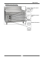
Specifications
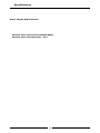
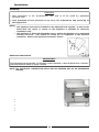
Electrical supply connection point is located at the rear of the appliance, approximately 87 mm from
the left hand side, 557 mm from the rear and 335 mm (290 mm for BP8120E/EE) from the floor.
Water Supply Requirements
Cold water connection is 1/2" tube connection via 15 mm crox fitting located 280 mm from the LH side,
575 mm from rear and 241 mm from the floor.
The water supply must be protected by an 'In-Line' sediment filter / strainer, which should be fitted into
the pipeline prior to the Bratt Pan water connection.
Maximum water supply pressure 550kPa (80psi).
Maximum water inlet temperature - 80°C.
4
Specifications
Dimensions BP(L)8080E Model Only
5
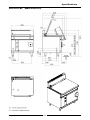
Specifications
Dimensions BP(L)8080EE Model Only
6
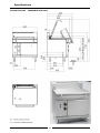
Specifications
Dimensions BP(L)8120E Model Only
7
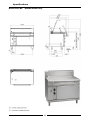
Specifications
Dimensions BP(L)8120EE Model Only
8
Installation
Installation Requirements
NOTE:
• It is most important that this appliance is installed correctly and that operation is
correct before use. Installation shall comply with local electrical and health and
safety requirements.
• This appliance shall be installed with sufficient ventilation to prevent the occurrence
of unacceptable concentrations of health harmful substances in the room, the
appliance is installed in.
Waldorf Bratt Pans are designed to provide years of satisfactory service and correct installation is essential
to achieve the best performance, efficiency and trouble-free operation.
This appliance must be installed in accordance with National installation codes and in addition, in
accordance with relevant National / Local codes covering electrical, fire and health and safety.
Australia / New Zealand:
United Kingdom:
AS / NZS 3000
AS / NZS 3500
BS 7671
- Wiring Rules.
- Plumbing and Drainage.
- Requirements for Electrical Installations.
Installations must be carried out by authorised persons only. Failure to install equipment to
the relevant codes and manufacturer’s specifications shown in this section will void the
warranty.
Components having adjustments protected (e.g. paint sealed) by the manufacturer are only to
be adjusted by an authorised service agent. They are not to be adjusted by the installation
person.
Unpacking
1.
2.
3.
4.
Remove all packaging and transit protection from the appliance including all protective plastic
coating from the exterior stainless steel panels.
Check equipment and parts for damage. Report any damage immediately to the carrier and
distributor.
Report any deficiencies to the distributor who supplied the appliance.
Check that the available electrical supply is correct to that shown on the rating plate located on the
bottom right hand corner of the bottom sill.
Location
1.
2.
3.
4.
5.
Any appliance requires adequate clearance and ventilation for optimum and trouble-free operation.
The following minimum installation clearances are to be adhered to:
Never directly connect a ventilation system to the appliance flue outlet.
Installation must include adequate ventilation means, to prevent dangerous build up of combustion
products.
Position the Bratt Pan in its approximate working position.
The legs must always be fitted to the unit.
NOTE: Do not block or obstruct the appliance flue.
Clearances
NOTE: Only non-combustible materials can be used in close proximity to this appliance.
Combustible Surface
Non Combustible Surface
Left / Right Hand Side (*)
50 mm
0 mm
Rear
50 mm
0 mm
(*)
Side clearances can be 50 mm when the adjacent surface is at least 100 mm below the cooking
surface.
9
Installation
Assembly
C AUTIO N :
• This appliance is for professional use and is to be used by qualified
persons only.
• Only qualified service persons are to carry out installation and servicing of
this appliance.
NOTE:
• This appliance must only be installed on the adjustable feet supplied. It must not be
fitted with rear rollers or castors as this appliance is intended for stationary
installations only.
• This appliance is fitted with adjustable feet to enable the appliance to be positioned
securely and level. This should be carried out on completion of the electrical
connection. Refer to the 'Electrical Connection' section.
Nut
1.
2.
3.
4.
Check that all the feet are in place and are tightened firmly.
Roughly adjust the four feet to make the bratt pan steady and level.
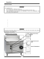
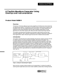
To assemble the handle to the lid, unpack the handle assembly. Place
the handle on the outside of the lid with the curved part of the handle
facing downwards. (Refer to Fig 1).
Fit the bolts with spring washers and flat washers from the inside of
the lid and tighten the bolts to secure the handle in position.
Spring & Flat
Washers
Handle
Electrical Connection
Fig 1
WARNING:
THIS APPLIANCE MUST BE EARTHED. IF THE SUPPLY CORD IS DAMAGED, IT MUST BE REPLACED BY A SUITABLY
QUALIFIED PERSON IN ORDER TO AVOID A HAZARD.
NOTE: ALL ELECTRICAL CONNECTIONS MUST ONLY BE CARRIED OUT BY AN AUTHORISED
PERSON.
Each appliance should be connected to an adequately protected power supply and an isolation switch
mounted adjacent to, but not behind the appliance. This switch must be clearly marked and readily
accessible in case of fire.
1.
2.
3.
4.
5.
6.
7.
8.
Check that the electricity supply is correct as shown on the Rating
Plate attached to the lower front hand side of the front sill panel.
The supply terminal connections are located at the rear of the the
appliance. Refer to ‘Electrical Connections’ in the ‘Specifications’
section of the manual.
Refer to the appropriate wiring standards for the size of cable
that is to be used for the current drawn on that line.
When connecting a Waldorf electric appliance to the main supply,
ensure that the following is carried out:•
An isolating switch is fitted nearby and accessible.
•
Supply wires are the correct size for the current drawn.
•
The fuse('s) on the wall are the correct current rating.
•
A grommet is fitted around the wiring entry holes into the appliance.
•
Wiring connection must be tight.
Rating Plate
Location
Remove the front panel and control panel to allow connection access for the electrical supply.
Connect the mains supply to L1, L2 and L3 fuse carrier connections for 3 phases.
Connect neutral and earth conductors to neutral stud and earth stud respectively.
For all connections ensure that conductors are secure and appropriately terminated.
10
Fig 2
Installation
NOTE:
• This appliance must be grounded / earthed.
• Fixed wiring installations must incorporate an all-pole disconnection switch.
9.
10.
11.
Correctly locate the appliance into its final operating position and using a spirit level, adjust the legs
so that the appliance is level and at the correct height.
Connect the power supply to the appliance.
Check that the electrical supply is as shown in 'Specifications' section of this manual.
Water Connection
NOTE:
• The water supply must be protected by an 'In-Line' sediment filter / strainer, which
should be fitted into the pipeline prior to the Bratt Pan water connection.
• All water pipework must be thoroughly flushed prior to completion of the installation
procedure.
Cold water mains ¾” BSP male thread connection point. For location details on services connections refer
to the drawings in the ‘Specification’ section.
•
Maximum water supply pressure
- 550kPa (80 psi).
•
Maximum Water Supply Temperature
- 80°C.
•
Remove the control panel for access to the cold water connection.
Commissioning
1.
Before leaving the new installation;
a. Check the following functions in accordance with the operating instructions specified in the
‘Operation’ section of this manual.
•
Ensure that all water pipework has been thoroughly flushed through prior to using the
appliance.
•
Check the current draw and loading for the equipment. Refer specification section for
correct electrical requirements.
•
Check that all the connections are correct and that all cover panels have been re-fitted.
•
Check that the appliance functions in accordance with the operating instructions.
•
Ensure that this instruction manual is left with the appliance.
•
Ensure that all the relevant details and contacts have been added to the front of this
manual.
b. Ensure that the operator has been instructed in the areas of correct operation and shutdown
procedure for the appliance.
2.
This manual must be kept by the owner for future reference and as a record of Date of Purchase,
Date of Installation and Serial Number of the Unit recorded and kept with this manual.
(These details can be found on the Rating Plate attached to the bottom corner of the
front right hand sill panel. Refer to the ‘Electrical Connection’ section).
NOTE:
• If for some reason it is not possible to get the appliance to operate correctly, turn off
the electrical power supply and contact a qualified service person. The supplier of
this appliance will be able to recommend a suitable person.
• Make sure that the electrical supply is turned off before any service or maintenance
work is carried out.
11
Operation
Operation Guide
CAUTION:
This appliance is;
•
Not suitable for shallow frying use.
•
•
For professional use and is to be used by qualified persons only.
1.
Waldorf bratt pans have been designed to provide simplicity of operation and 100% safety
protection.
Improper operation is therefore almost impossible, however bad operation practices can reduce the
life of the bratt pan and produce a poor quality product. To use this bratt pan correctly please
carefully read the following sections.
2.
Only qualified service persons are allowed to carry out installation and
servicing of this appliance.
•
Description of the Controls.
•
Turning on the Heating Element.
•
Setting the Temperature.
•
Operating the Water Supply Valve.
•
Tilting the Pan.
•
Turning Off the Main Element.
CAUTION:
The pan lid and the ends of its handle close to the lid can become hot during
operation of this appliance.
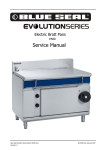
Description of Controls
Water Flow Control
Valve
BP8080E and BP8120E Models.
OFF Position
Graduated Flow
Heating Indicator
Lamp (Amber)
Temperature Control
Knob
Graduations from 1
to 10 for heat
control.
Manual Tilt Handwheel
Power Indicator
Lamp (Green)
Fig 3
12
Operation
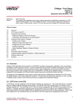
BP8080EE and BP8120EE Models.
Water Flow Control
Valve
OFF Position
Graduated Flow
Heating Indicator
Lamp (Amber)
Temperature Control
Knob
Graduations from 1
to 10 for heat
control.
Power Indicator
Lamp (Green)
Fig 4
13
Electrical Tilt Controls
With the bratt pan lid
open, the bratt pan can
be electrically raised to
the ‘UP’ position.
Operation
Turning on the Main Element and Setting the Desired Temperature
1.
2.
3.
Rotate the thermostat control knob anti-clockwise to the desired heat setting.
The main element will only operate when the pan is in the flat cooking position. Tilting the pan will
automatically cut power to the main element.
Turn the thermostat control knob to the desired heat setting. The temperature will be
thermostatically controlled at this selected heat setting.
Operating the Water Supply Valve
1.
2.
3.
The temperature control thermostat should be turned ON to hold solenoid water supply valve open
and allow water supply to the appliance.
To add water to the cooking product or for cleaning, turn the water tap anti-clockwise with the pan
in the down position and the pan lid up.
The water flow can be controlled by adjusting the water tap position.
NOTE: A ¼ turn anti-clockwise is FULLY open.
Tilting the Pan
WARNING:
CHECK THAT THE PAN LID IS IN THE FULLY RAISED POSITION BEFORE TILTING THE PAN UP.
CHECK THAT THE SPACE BEHIND AND ON BOTH SIDES OF THE PAN IS CLEAR OF ANY OBSTRUCTIONS BEFORE
TILTING THE PAN DOWN.
BP8080E and BP8120E Models
a. To tilt the pan, turn the pan tilt handle clockwise. The heating element will automatically switch
‘Off’ when the pan is raised.
b. With the pan returned to its down lowered, the heating element will turn back ‘On’.
BP8080EE and BP8120EE Models
a. To tilt the pan up or down, depress the pan tilt control switches on the front panel, with the
corresponding direction arrow marking and hold the pan tilt control switch depressed as long as
required.
b. Releasing the switch will stop the tilt operation and the pan will rest in the chosen position.
NOTE: The electric lift mechanism will only operate if the pan lid is in the raised position.
Turning ‘Off’ the Main Element
1.
To turn ‘Off’ the main element, set the thermostat control knob to the ‘OFF’ position. The main
element will now switch ‘Off’.
14
Cleaning and Maintenance
C AUTIO N :
Always turn off the electrical supply before commencing any cleaning.
This appliance is not water proof.
Do Not use water jet spray to clean interior or exterior of this appliance.
General
Clean the bratt pan regularly. A clean appliance looks better, will last longer and will perform better.
A dirty cooking surface will hinder the transfer of heat from the cooking surface to the food. This will
result in loss of cooking efficiency.
C AUTIO N :
If cleaning detergents are allowed to enter the inner parts of the appliance,
rusting will occur on the pipe work, installation elements, heating
elements and electrical components, this will cause premature failure of the
appliance.
NOTE:
• DO NOT clean the appliance using high pressure water or steam jets.
• DO NOT pour water directly over the appliance.
• DO NOT use wire brushes. Clean the pan regularly after each use.
• DO NOT use combustible liquids to clean the appliance.
• DO NOT use harsh abrasive detergents, sharp scrapers, strong solvents or caustic
detergents as they will damage the appliance.
• DO NOT use any chloric or bleaching detergents to clean the appliance.
• DO NOT use saline or sulfuric acid preparations for descaling the appliance.
• Ensure that protective gloves are worn during the cleaning process.
• Clean the pan regularly after each use.
After Each Use
Clean the interior of the pan regularly after each use. Do not use wire brushes on the pan. Clean using a
mild detergent and a hot water solution using soft cloth or a soft bristled brush. Dry the appliance
thoroughly using a dry clean cloth.
Clean the exterior of the bratt pan using a mild detergent and a hot water solution using soft cloth or a soft
bristled brush.
Daily Cleaning
Clean the bratt pan control panel of the using a soft cloth moistened with a solution of mild detergent and
hot water. DO NOT USE EXCESSIVE WATER. Dry the control panel thoroughly using a dry clean cloth.
Clean the interior and exterior of the bratt pan using a mild detergent and a hot water solution using soft
cloth or a soft bristled brush. Do not use wire brushes on the pan. Dry the appliance thoroughly using a
dry clean cloth.
Clean the control panel with a damp cloth lightly moistened with a solution of mild detergent and water.
Wipe dry with a clean dry cloth.
15
Cleaning and Maintenance
Weekly Cleaning
NOTE:
• If the bratt pan usage is very high, we recommend that the weekly cleaning
procedure is carried out on a more frequent basis.
• Ensure that protective gloves are worn during the cleaning process.
• DO NOT use harsh abrasive detergents, strong solvents, sharp scrapers or caustic
detergents as they will damage the surface of the bratt pan.
• DO NOT use water on the elements while they are still hot as cracking may occur.
Allow these items to cool prior to cleaning.
• DO NOT clean the elements in a dishwasher.
Thoroughly clean the interior and exterior of the bratt pan regularly. Do not use wire brushes on the pan.
Clean using a mild detergent and a hot water solution using soft cloth or a soft bristled brush. Dry the
appliance thoroughly using a dry clean cloth.
NOTE: In order to prevent the forming of rust on the steel components, ensure that the
detergent or cleaning material has been entirely removed after each cleaning
process.
Stainless Steel Surfaces
a. Clean the interior and exterior surfaces of the bratt pan with hot water, a mild detergent solution
and a soft scrubbing brush. Note that the control knobs are a push fit onto the thermostat and
water control valve spindles and can be removed to allow cleaning of the front of the control
panel.
b. Baked on deposits or discolouration may require a good quality stainless steel cleaner or stainless
steel wool. Always apply cleaner when the appliance is cold and rub in the direction of the grain.
c. It should not be necessary to remove the manual tilt mechanism handwheel for cleaning
purposes.
d. Dry all components thoroughly with a dry cloth and polish with a soft dry cloth.
e. To remove any discolouration, use an approved stainless steel cleaner or stainless steel wool.
Always rub in the direction of the grain.
Periodic Maintenance
To achieve the best results, cleaning must be regular and thorough and all controls and mechanical parts
checked and adjusted periodically by a competent serviceman. If any small faults occur, have them
attended to promptly. Don't wait until they cause a complete breakdown. It is recommended that the
appliance is serviced every 6 months.
16
Fault Finding
This section provides an easy reference guide to the more common problems that may occur during the
operation of your equipment. The fault finding guide in this section is intended to help you correct, or at
least accurately diagnose problems with your equipment.
Although this section covers the most common problems reported, you may encounter a problem not
covered in this section. In such instances, please contact your local authorised service agent who will
make every effort to help you identify and resolve the problem. Please note that the service agent will
require the following information:• The Model Trade Name and the Serial Number of the Appliance. (both can be found on
the Technical Data Plate located on the appliance. (Refer to the ‘Dimensions’ section).
Fault
Possible Cause
Remedy
O v e r - t e m p e r a t u r e Over-temperature thermostat faulty.
thermostat cuts out
If the main element turns ‘Off’
and the power indicator light also
drops below 320ºC, replace the
over-temperature thermostat.
Control thermostat not maintaining a set
temperature.
a. Thermostat out of calibration.
b. Thermostat does not open on temperature rise.
Check continuity through the
thermostat leads, on temperature
rise. If the circuit does not open,
replace the thermostat.
Thermostat opens on temperature rise Check connections to the heating
but control valve does not respond.
element are correct. If correct,
replace the heating element.
Call service provider.
Main Element
operate
does
not Check power is supplied to the unit.
Turn on the power.
Check that the pan is flat and that the tilt Adjust the microswitch so that the
microswitch is closed.
microswitch is activated when the
pan is fully down in the flat
(cooking position).
Check that the thermostat setting is Replace the thermostat.
correct and that the control knob on the
main element is set to the 'ON' position.
No pan
available.
filling
water With the pan in the down position,
control thermostat turned 'ON' and main
water supply 'ON', check that the
(The manual water fill valve solenoid valve has electrical power
has an electrical solenoid across its coil terminals.
isolating valve fitted to the a. If solenoid coil has power, but no
supply side of the water
water available on turning the manual
supply plumbing in the
valve, check the coil for open circuit,
appliance.
The shut-off
short circuit and for solenoid coil burnvalve only opens water
out.
supply to the manual valve b. If the solenoid coil is satisfactory, diswhen the pan is in the down
connect the water connection and
position and when the
check the inlet filter screen for foreign
control thermostat is turned
matter blockage.
'ON').
a. If there is
solenoid coil.
no
voltage
17
to
Replace the solenoid.
Clean and refit the inlet filter.
Check for electrical fault in pan lift
microswitch circuit. A fault here is
likely to also cause main element
to fail.
the Call service provider.
PAN
3
3
1
3
3
L1
3
1
L2
3
1
15
23
N
4
L3
18
22
GND
= OPEN SIDE THIS WAY
13
20
1
A1
3
5
13
2
4
2
6
2
14
2
2
4
6
14
15
BXF 79 240
SUPPRESSOR
231746
24
21
A2
12
231739
HEAT
5
A2
19
BF18 CONTACTOR
3
8
231739
SAFETY
A1
EARTH
STUD
22
BF18 CONTACTOR
1
5
4
23
EARTH
STUD
16
6
14
6
5
NO
NC
19
16
NC
NO
17
COM
OVERTEMP
025400
7
COM
WATER
MICROSWITCH
003004
WATER
SOLENOID
020851
12
11
5
10
NEON
GREEN
227962
1
CONTROL PANEL
17
2
P5
9
NEON
AMBER
227963
THERMOSTAT
011987
21
10
E
8
24
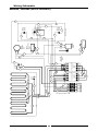
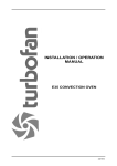
Wiring Schematic
BP8080E / BP8120E (Manual Tilt Models)
PAN
1
3
L1
3
1
3
1
3
3
25
N
= OPEN SIDE THIS WAY
22
30
31
5
A1
3
EARTH
STUD
5
9
13
A2
27
2
4
6
2
2
14
2
BF18 CONTACTOR
231739
SAFETY
1
4
28
3
5
30
13
29
A2
13
2
4
6
231739
HEAT
14
BF18 CONTACTOR
1
A1
31
22
BXF 79 240
SUPPRESSOR
231746
32
33
23
7
20
17
7
5
NO
NC
8
23
24
COM
33
PAN DOWN
MICROSWITCH
024802
NC
NO
OVERTEMP
025400
27
COM
WATER
MICROSWITCH
003004
WATER
SOLENOID
020851
13
12
5
11
NEON
GREEN
227962
1
6
CONTROL PANEL
E
24
2
P5
10
NEON
AMBER
227963
THERMOSTAT
011987
29
11
9
17
E
16
19
PAN UP
MICROSWITCH
024802
NC
NO
WHITE
BLUE
RED
GREEN
32
15
COM
18
14
TERMINAL BLOCK
025950
LH COVER PANEL
14
25
34
GREEN
W2
BLUE
U2
RED
V2
WHITE
N/O
N/O
EARTH
STUD
Motor
228930
MOTOR TERMINATION BOX, WIRING DETAIL
N/C
N/C
3
L2
4
L3
19
GND
34
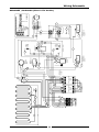
Wiring Schematic
BP8080EE / BP8120EE (Electric Tilt Models)
Replacement Parts List
Replacement Parts List
IMPORTANT:
Only genuine authorized replacement parts should be used for the servicing and
repair of this appliance. The instructions supplied with the parts should be followed
when replacing components.
For further information and servicing instructions, contact your nearest authorized
service branch (contact details are as shown on the reverse of the front cover of this
manual).
When ordering replacement parts, please quote the part number and the description as listed below. If the
part required is not listed below, request the part by description and quote Model and Serial Number which
is shown on the rating plate.
Bratt Pan
229084
229085
011987
025400
231739
227963
227962
024802
003004
020062
227915
020851
227848
228849
228716
227521
228822
227387
227857
020043
228123
228117
N044400
044066
227850
Main Element (900 mm Wide).
Main Element (1200 mm Wide).
Thermostat 50°C - 320°C.
Over-Temp Thermostat.
Contactor.
Indicator Neon (Orange).
Indicator Neon (Green).
Microswitch (Bratt Pan Raise - Lower).
Microswitch (Water Valve).
Water Control Valve.
Water Valve Handle.
Water Solenoid Valve.
Lid Handle (900 mm Wide).
Lid Handle (1200 mm Wide).
Lid Hinge Spring Kit.
Tensioner Barrel.
Thermostat Control Knob.
Water Control Knob.
Electric Motor (900mm & 1200 mm EE Models Only).
Bearing & Housing.
Handwheel.
Handwheel Spacer Bush.
Key Woodruff - 7 / 8 " x 5 / 32 ".
Handle Nut - M16 x 2.
Leg Assembly.
Accessories
228798
228802
Plinth Kit 900 mm.
Plinth Kit 1200 mm.
20
21
22