1
Electric Bratt Pans
E580
Service Manual
Blue Seal Evolution Series Electric Bratt Pans
Revision 1/
© Moffat Ltd, January 2007
WARNING:
ALL INSTALLATION AND SERVICE REPAIR WORK MUST BE CARRIED OUT BY
QUALIFIED PERSONS ONLY.
IMPORTANT: MAKING ALTERATIONS MAY VOID WARRANTIES AND APPROVALS.
Blue Seal Evolution Series Electric Bratt Pans
Revision 1/
© Moffat Ltd, January 2007
Contents
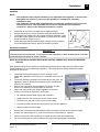
This manual is designed to take a more in depth look at the E580 Bratt Pans for the purpose of making the
units more understandable to service people.
There are settings explained in this manual that should never require to be adjusted, but for completeness
and those special cases where these settings are required to change, this manual gives a full explanation
as to how, and what effects will result.
Section
Page Number
1. Specifications.............................................................................................1
2. Installation................................................................................................6
3. Operation...................................................................................................8
4.
Cleaning / Maintenance............................................................................9
5. Trouble-shooting Guide...........................................................................10
6. Service
Procedures..................................................................................12
6.2 Access
6.3.
Replacement
6.4 Adjustment
/ Calibration
7. Accessories..............................................................................................22
8. Exploded
9. Circuit
Parts Diagrams........................................................................23
Diagrams......................................................................................24
10. Service Contacts......................................................................................26
Blue Seal Evolution Series Electric Bratt Pans
Revision 1/
© Moffat Ltd, January 2007
Blue Seal Evolution Series Electric Bratt Pans
Revision 1/
© Moffat Ltd, January 2007
Specifications
1
Electrical Requirements
E580-8/8E
E580-12/12E
400 - 415Vac, 3P+N+E
400 – 415Vac, 3P+N+E
Power (@ 415Vac)
12kW
17kW
Phase Loading (A)
L1=16.4, L2=16.4, L3=16.4
L1=23.2, L2=23.2, L3=23.2
Voltage
Bratt Pan Dimensions
Model E580-8/8E
Model E582-12/12E
Overall Dimensions
Height to Lid
915 mm
915 mm
Height to Splashback
1130 mm
1130 mm
Width
900 mm
1200mm
Depth
805 mm
805 mm
Height with Lid Open
1600mm
1600mm
Height
215 mm
215mm
Width
810 mm
1080mm
Depth (front to back)
500 mm
500mm
Pan Volume
75 litres
120 litres
Weight
192 kg
Pan Internal Dimensions
Clearances
Combustible surface
Non-Combustible surface
Rear
50mm
0mm
Left-hand side
50mm
0mm
Right-hand side
50mm
0mm
Water Supply Requirements
Cold water connection 1/2" tube connection via 15mm crox fitting located 280mm from LH side, 574mm
from rear and 241mm from the floor.
Maximum water supply pressure 550 kPa (80 psi).
1
Blue Seal Evolution Series Electric Bratt Pans
Revision 1/
© Moffat Ltd, January 2007
1
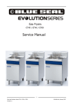
Specifications
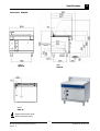
Dimensions E580-8
FRONT
SIDE
E580-8
E580-8
PLAN
E580-8
Electrical Connection Point.
Water Connection Point.
2
Blue Seal Evolution Series Electric Bratt Pans
Revision 1/
© Moffat Ltd, January 2007
Specifications
1
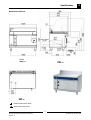
Dimensions E580-8E
FRONT
SIDE
E580-8E
E580-8E
PLAN
E580-8E
Electrical Connection Point.
Water Connection Point.
3
Blue Seal Evolution Series Electric Bratt Pans
Revision 1/
© Moffat Ltd, January 2007
1
Specifications
Dimensions E580-12
FRONT
E580-12
SIDE
E580-12
PLAN
E580-12
Electrical Connection Point.
Water Connection Point.
4
Blue Seal Evolution Series Electric Bratt Pans
Revision 1/
© Moffat Ltd, January 2007
Specifications
1
Dimensions E580-12
FRONT
E580-12
SIDE
E580-12
PLAN
E580-12
Electrical Connection Point.
Water Connection Point.
5
Blue Seal Evolution Series Electric Bratt Pans
Revision 1/
© Moffat Ltd, January 2007
2
Installation
Installation Requirements
NOTE:
• It is most important that this appliance is installed correctly and that operation is
correct before use. Installation shall comply with local electrical and health and
safety requirements.
• This appliance shall be installed with sufficient ventilation to prevent the occurrence
of unacceptable concentrations of health harmful substances in the room, the
appliance is installed in.
Blue Seal Bratt Pans are designed to provide years of satisfactory service and correct installation is
essential to achieve the best performance, efficiency and trouble-free operation.
This appliance must be installed in accordance with National installation codes and in addition, in
accordance with relevant National / Local codes covering electrical, fire and health and safety.
Australia / New Zealand:
United Kingdom:
AS / NZS3000
BS 7671
- Wiring Rules.
- Requirements for Electrical Installations.
Installations must be carried out by authorised persons only. Failure to install equipment to
the relevant codes and manufacturer’s specifications shown in this section will void the
warranty.
Components having adjustments protected (e.g. paint sealed) by the manufacturer are only to
be adjusted by an authorised service agent. They are not to be adjusted by the installation
person.
Unpacking
1.
2.
3.
4.
Remove all packaging and transit protection from the appliance including all protective plastic
coating from the exterior stainless steel panels.
Check equipment and parts for damage. Report any damage immediately to the carrier and
distributor.
Report any deficiencies to the distributor who supplied the appliance.
Check that the available electrical supply is correct to that shown on the rating plate located on the
bottom right hand corner of the bottom sill.
Location
1.
2.
3.
4.
5.
Any appliance requires adequate clearance and ventilation for optimum and trouble-free operation.
The following minimum installation clearances are to be adhered to:
Never directly connect a ventilation system to the appliance flue outlet.
Installation must include adequate ventilation means, to prevent dangerous build up of combustion
products.
Position the Bratt Pan in its approximate working position.
The legs must always be fitted to the unit.
NOTE: Do not block or obstruct the appliance flue.
Clearances
NOTE: Only non-combustible materials can be used in close proximity to this appliance.
Combustible Surface
Non Combustible Surface
Left / Right Hand Side
50 mm
0 mm
Rear
50 mm
0 mm
•
Side clearances can be 50 mm when the adjacent surface is at least 100 mm below the
cooking surface.
6
Blue Seal Evolution Series Electric Bratt Pans
Revision 1/
© Moffat Ltd, January 2007
Installation
2
Assembly
NOTE:
• This appliance must only be installed on the adjustable feet supplied. It must not be
fitted with rear rollers or castors as this appliance is intended for stationary
installations only.
• This appliance is fitted with adjustable feet to enable the appliance to be positioned
securely and level. This should be carried out on completion of the electrical
connection. Refer to the 'Electrical Connection' section.
1.
2.
3.
4.
Check that all the feet are in place and are tightened firmly.
Roughly adjust the four feet to make the bratt pan steady and level.
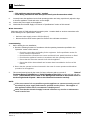
To assemble the handle to the lid, unpack the handle assembly. Place
the handle on the outside of the lid with the curved part of the handle
facing downwards. (Refer to Fig 1).
Fit the bolts with spring washers and flat washers from the inside of
the lid and tighten the bolts to secure the handle in position.
Nut
Spring & Flat
Washers
Handle
Electrical Connection
Fig 1
WARNING:
THIS APPLIANCE MUST BE EARTHED. IF THE SUPPLY CORD IS DAMAGED, IT MUST BE REPLACED BY A SUITABLY
QUALIFIED PERSON IN ORDER TO AVOID A HAZARD.
NOTE: ALL ELECTRICAL CONNECTIONS MUST ONLY BE CARRIED OUT BY AN AUTHORISED
PERSON.
Each appliance should be connected to an adequately protected power supply and an isolation switch
mounted adjacent to, but not behind the appliance. This switch must be clearly marked and readily
accessible in case of fire.
1.
2.
3.
4.
Check that the electricity supply is correct as shown on the
Rating Plate attached to the lower front hand side of the front sill
panel.
The supply terminal connections are located at the rear of the the
appliance. Refer to ‘Electrical Connections’ in the ‘Specifications’
section of the manual.
Refer to the appropriate wiring standards for the size of cable
that is to be used for the current drawn on that line.
When connecting a Blue Seal electric appliance to the main
supply, ensure that the following is carried out:•
An isolating switch is fitted nearby and accessible.
•
Supply wires are the correct size for the current drawn.
•
The fuse('s) on the wall are the correct current rating.
•
A grommet is fitted around the wiring entry holes into the appliance.
•
Wiring connection must be tight.
Rating Plate
Location
Fig 2
5.
Remove the front panel and control panel to allow connection access for the electrical supply.
6.
Connect the mains supply to L1, L2 and L3 fuse carrier connections for 3 phases.
7.
Connect neutral and earth conductors to neutral stud and earth stud respectively.
8.
For all connections ensure that conductors are secure and appropriately terminated.
7
Blue Seal Evolution Series Electric Bratt Pans
Revision 1/
© Moffat Ltd, January 2007
2
Installation
NOTE:
• This appliance must be grounded / earthed.
• Fixed wiring installations must incorporate an all-pole disconnection switch.
9.
10.
11.
Correctly locate the appliance into its final operating position and using a spirit level, adjust the legs
so that the appliance is level and at the correct height.
Connect the power supply to the appliance.
Check that the electrical supply is as shown in “Specifications” section of this manual.
Water Connection
Cold water mains ¾” BSP male thread connection point. Location detail on services connections refer
to the drawings in the “Specification” section.
•
Maximum water supply pressure 550 kPa (80 psi).
•
Remove the front lower service panel for access to the cold water connection.
Commissioning
1.
Before leaving the new installation;
a. Check the following functions in accordance with the operating instructions specified in the
‘Operation’ section of this manual.
•
Check the current draw and loading for the equipment. Refer specification section for
correct electrical requirements.
•
Check that all the connections are correct and that all cover panels have been re-fitted.
•
Check that the appliance functions in accordance with the operating instructions.
•
Ensure that this instruction manual is left with the appliance.
•
Ensure that all the relevant details and contacts have been added to the front of this
manual.
b. Ensure that the operator has been instructed in the areas of correct operation and shutdown
procedure for the appliance.
2.
This manual must be kept by the owner for future reference and as a record of
Date of
Purchase, Date of Installation and Serial Number of the Unit recorded and kept with this
manual. (These details can be found on the Rating Plate attached to the bottom corner of
the front right hand sill panel. Refer to the ‘Electrical Connection’ section).
NOTE:
• If for some reason it is not possible to get the appliance to operate correctly, turn off
the electrical power supply and contact a qualified service person. The supplier of
this appliance will be able to recommend a suitable person.
• Make sure that the electrical supply is turned off before any service or maintenance
work is carried out.
8
Blue Seal Evolution Series Electric Bratt Pans
Revision 1/
© Moffat Ltd, January 2007
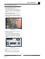
Operation
3.1 User
3
Operation
NOTE: A full user’s operation manual is supplied with the product and can be used for further referencing
of installation, operation and service.
1.
2.
Waldorf bratt pans have been designed to provide simplicity of operation and 100% safety
protection.
Improper operation is therefore almost impossible, however bad operation practices can reduce the
life of the bratt pan and produce a poor quality product. To use this bratt pan correctly please carefully read the following sections.
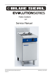
E580-8 & E580-12 (Manual lift models)
Water Flow
Control Valve
OFF Position
Heating
Graduated Flow
Temperature
Control Knob
Graduations
from 1 to 10 for
heat control.
Manual Tilt
Handwheel
Power
E580-8E & E580-12E (Electric lift models)
Water Flow
Control Valve
OFF Position
Heating
Indicator
Graduated Flow
Temperature
Control Knob
Graduations
from 1 to 10 for
heat control.
Power
Electrical Tilt
Controls
With the bratt pan
lid open, the bratt
pan can be
electrically raised to
the ‘UP’ position.
9
Blue Seal Evolution Series Electric Bratt Pans
Revision 1/
© Moffat Ltd, January 2007
4
Cleaning / Maintenance
CAUTION:
Always turn off the electrical supply before commencing any cleaning.
This appliance is not water proof.
Do Not use water jet spray to clean interior or exterior of this appliance.
General
Clean the bratt pan regularly. A clean appliance looks better, will last longer and will perform better.
A dirty cooking surface will hinder the transfer of heat from the cooking surface to the food. This will
result in loss of cooking efficiency.
CAUTION:
If cleaning detergents are allowed to enter the inner parts of the appliance,
rusting will occur on the pipe work, installation elements, heating
elements and electrical components, this will cause premature failure of the
appliance.
NOTE:
• DO NOT clean the appliance using high pressure water or steam jets.
• DO NOT pour water directly over the appliance.
• DO NOT use wire brushes. Clean the pan regularly after each use.
• DO NOT use combustible liquids to clean the appliance.
• DO NOT use harsh abrasive detergents, sharp scrapers, strong solvents or caustic
detergents as they will damage the appliance.
• DO NOT use any chloric or bleaching detergents to clean the appliance.
• DO NOT use saline or sulfuric acid preparations for descaling the appliance.
• Ensure that protective gloves are worn during the cleaning process.
• Clean the pan regularly after each use.
After Each Use
Clean the interior of the pan regularly after each use. Do not use wire brushes on the pan. Clean using a
mild detergent and a hot water solution using soft cloth or a soft bristled brush. Dry the appliance
thoroughly using a dry clean cloth.
Clean the exterior of the bratt pan using a mild detergent and a hot water solution using soft cloth or a soft
bristled brush.
Daily Cleaning
Clean the interior and exterior of the bratt pan using a mild detergent and a hot water solution using soft
cloth or a soft bristled brush. Do not use wire brushes on the pan. Dry the appliance thoroughly using a
dry clean cloth.
10
Blue Seal Evolution Series Electric Bratt Pans
Revision 1/
© Moffat Ltd, January 2007
Cleaning / Maintenance
4
Weekly Cleaning
NOTE:
• If the bratt pan usage is very high, we recommend that the weekly cleaning
procedure is carried out on a more frequent basis.
• Ensure that protective gloves are worn during the cleaning process.
• DO NOT use harsh abrasive detergents, strong solvents, sharp scrapers or caustic
detergents as they will damage the surface of the bratt pan.
• DO NOT use water on the elements while they are still hot as cracking may occur.
Allow these items to cool prior to cleaning.
• DO NOT clean the elements in a dishwasher.
Thoroughly clean the interior and exterior of the bratt pan regularly. Do not use wire brushes on the pan.
Clean using a mild detergent and a hot water solution using soft cloth or a soft bristled brush. Dry the
appliance thoroughly using a dry clean cloth.
NOTE: In order to prevent the forming of rust on the steel components, ensure that the
detergent or cleaning material has been entirely removed after each cleaning
process.
Stainless Steel Surfaces
a. Clean the interior and exterior surfaces of the bratt pan with hot water, a mild detergent solution
and a soft scrubbing brush. Note that the control knobs are a push fit onto the thermostat and
water control valve spindles and can be removed to allow cleaning of the front of the control
panel.
b. Baked on deposits or discolouration may require a good quality stainless steel cleaner or stainless
steel wool. Always apply cleaner when the appliance is cold and rub in the direction of the grain.
c. It should not be necessary to remove the manual tilt mechanism handwheel for cleaning
purposes.
d. Dry all components thoroughly with a dry cloth and polish with a soft dry cloth.
e. To remove any discolouration, use an approved stainless steel cleaner or stainless steel wool.
Always rub in the direction of the grain.
Periodic Maintenance
To achieve the best results, cleaning must be regular and thorough and all controls and mechanical parts
checked and adjusted periodically by a competent serviceman. If any small faults occur, have them
attended to promptly. Don't wait until they cause a complete breakdown. It is recommended that the
appliance is serviced every 6 months.
11
Blue Seal Evolution Series Electric Bratt Pans
Revision 1/
© Moffat Ltd, January 2007
5
Trouble-shooting
WARNING:
5.1
ALL INSTALLATION AND SERVICE REPAIR WORK MUST BE CARRIED OUT BY
QUALIFIED PERSONS ONLY.
Trouble Shooting Chart
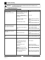
Fault
Pan does not heat.
(Green light not illuminated)
Possible cause
Remedy
The mains isolating switch on the
wall, circuit breaker, or fuses are
off at the power board.
Turn on.
The pan is not fully lowered.
(Unit will not operate when pan is
fully raised)
Lower pan.
The pan micro switch is out of
adjustment or faulty.
Adjust or replace microswitch as
required.
(Refer service section 6.2.6)
Thermostat switch is faulty.
Replace.
(Refer service section 6.2.1)
Thermostat faulty.
Replace.
(Refer service section 6.2.1)
Overtemp thermostat tripped or
faulty.
Reset / replace overtemp.
(Refer service section 6.2.5)
Safety contacter faulty.
Replace.
(Refer service section 6.2.3)
Heating contacter faulty.
Replace.
(Refer service section 6.2.3)
Pan slow to heat up / recover
heat.
One element faulty.
Replace
(Refer service section 6.2.4)
No Water
Water supply turned off at the
mains.
Turn on the water supply.
Pan is raised (water tap only
operates when pan is in the
lower position.
Lower the pan.
Pan microswitch is out of
adjustment.
Adjust pan microswitch.
(Refer service section 6.3.1)
Water solenoid valve blocked
or faulty.
(Refer fault diagnosis 5.2.2)
Clean or replace water solenoid.
(Refer service section 6.2.8)
Water control microswitch is
out of adjustment.
Adjust water control microswitch.
(Refer service section 6.3.2)
Pan does not heat.
(Green light illuminated, but
amber light not illuminated)
Pan does not heat.
(Green and amber light both
illuminated)
12
Blue Seal Evolution Series Electric Bratt Pans
Revision 1/
© Moffat Ltd, January 2007
Trouble-shooting
Fault
Bratt pan lid will not stay up.
Pan will not lift.
(Electric lift models only)
Possible cause
5
Remedy
Hinges need adjusting
Adjust hinge springs.
(Refer service section 6.3.3)
Lid hinge springs are worn.
Replace lid hinge springs.
(Refer service section 6.2.12)
Bratt pan lid not raised.
Raise lid. (Lid must be raised in
order for pan to be lifted)
Push button switch contact
block faulty.
Replace
(Refer service section 6.2.15)
13
Blue Seal Evolution Series Electric Bratt Pans
Revision 1/
© Moffat Ltd, January 2007
6
Service Procedures
Section
Page Number
6.1 Access......................................................................................................13
6.1.1
Control Panel............................................................................................................13
6.2 Replacement............................................................................................14
6.2.1
6.2.2
6.2.3
6.2.4
6.2.5
6.2.6
6.2.7
6.2.8
6.2.9
6.2.10
6.2.11
6.2.12
6.2.13
6.2.14
6.2.15
6.2.16
Thermostat..............................................................................................................14
Selector Switch.........................................................................................................14
Contactors................................................................................................................14
Elements..................................................................................................................15
Overtemp Thermostat...............................................................................................16
Pan Microswitch........................................................................................................16
Water Valve..............................................................................................................16
Water Solenoid.........................................................................................................17
Water Solenoid Cleaning............................................................................................17
Water control Microswitch..........................................................................................17
Indicators.................................................................................................................17
Lid Hinge Springs......................................................................................................18
Hand Wheel Handle..................................................................................................18
Push Button Switch Block..........................................................................................19
Control Button..........................................................................................................19
Lift Motor.................................................................................................................19
6.3 Adjustment..............................................................................................20
6.3.1
6.3.3
6.3.4
6.3.2
Pan Microswitch (manual lift models)..........................................................................20
Pan Microswitch (electric lift models)..........................................................................20
Water Control Microswitch.........................................................................................20
Tensioning the Lid Springs.........................................................................................21
WARNING:
ALL INSTALLATION AND SERVICE REPAIR WORK MUST BE CARRIED OUT BY
QUALIFIED PERSONS ONLY.
14
Blue Seal Evolution Series Electric Bratt Pans
Revision 1/
© Moffat Ltd, January 2007
Service Procedures
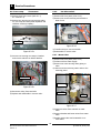
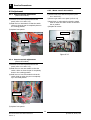
6.1.3 Right Front Panel
6.1 Access
6.1.1
6
Front Control Panel
Lifting Wheel
Three screws
Two Screws
Figure 6.1.3
Figure 6.1.1
1) Remove front control panel (refer 6.1.1)
1) Remove two screws from front control panel.
2) Prise off centre cap of lifting wheel, remove
centre nut and remove wheel. (Not GE)
2) Remove control knobs by pulling away from
control panel.
3) Remove three screws from left front panel
and slide panel to the left to release panel.
6.1.2
Left Front Panel
Two Screws
Figure 6.1.2
1) Remove front control panel (refer 6.1.1)
2) Remove two screws from left front panel and
slide panel to the left to release panel.
15
Blue Seal Evolution Series Electric Bratt Pans
Revision 1/
© Moffat Ltd, January 2007
6
Service Procedures
6.2.2 Selector
6.2 Replacement
Switch
1) Remove control panel (refer 6.1.1).
6.2.1 Thermostat
2) Slide thermostat off rear of selector switch.
1) Remove control and left front panels (refer
6.1.1, 6.1.2)
3) Slide knob off selector switch shaft.
4) Remove two screws securing selector switch to
control panel.
2) Lift pan fully up.
3) Remove two screws securing capillary locating
plate and remove capilery.
2 screws
Capillary plate
Figure 6.2.1b
Figure 6.2.1a
5) Transfer wires to the new selector switch.
6) Fit new selector switch and reassemble in
reverse order.
Thermostat
6.2.3 Contactors
1) Remove left front and control panel (refer
6.1.1 and 6..2)
2) Transfer wires from old contactor to new
contactor.
Figure 6.3.1b
4) Slide thermostat off rear of selector switch.
5) Transfer wires to the new thermostat.
6) Fit new thermostat and reassemble in reverse
order.
Contactors
Figure 6.2.3
3) Remove old contactor from din rail.
4) Fit new contactor and reassemble.
16
Blue Seal Evolution Series Electric Bratt Pans
Revision 1/
© Moffat Ltd, January 2007
Service Procedures
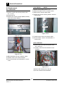
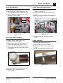
6.2.4 Elements
6
6) Remove twenty four brass element plate
nuts and lock nuts and allow plate to drop
down. Element can now be removed.
1) Lift lid and raise pan fully.
2) Remove four bolts holding element connection cover.
Element connection covers
Bolts
Figure 6.2.4d
Figure 6.2.4a
3) Remove wires from elements noting position
of wiring.
Element cover
Figure 6.2.4e
7) Reassemble in reverse order.
Figure 6.2.4b
4) Remove two screws securing capillary retaining plate and remove.
5) Remove two bolts from each end of the
element cover and allow the cover to drop
down. Care should be taken to clear element
ends.
Figure 6.2.4c
17
Blue Seal Evolution Series Electric Bratt Pans
Revision 1/
© Moffat Ltd, January 2007
6
Service Procedures
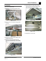
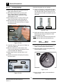
6.2.5 Over-temp
Thermostat
6.2.6
1) Remove three front covers (refer 6.1.1,
6.1.2 and 6.1.3)
Pan Microswitch
1) Remove left front panel (refer 6.1.2).
2) Remove two screws securing microswitch to
base of unit.
2) Remove two 4mm hex screws securing plate
for over-temp and thermostat capillaries and
withdraw overtemp capillary.
Capillaries
Microswitch
Figure 6.2.6
3) Transfer wiring to new microswitch.
4) Reassemble in reverse order.
Figure 6.2.5a
6.2.7 Water Valve
3) Unscrew nut securing over-temp to bracket
and remove switch from behind bracket.
1) Remove left front panel (refer 6.1.2)
2) Isolate unit from water supply.
3) Remove two nuts securing water piping to
valve.
4) Undo two screws securing water valve to the
mounting panel.
Overtemp switch
Two screws
Figure 6.2.5b
4) Disconnect wiring from terminals.
Water valve
5) Replace and reassemble in reverse order.
Solenoid
Figure 6.2.7
5) Disconnect wires from solenoid on water
valve.
6) Remove bracket and brass unions from water
valve.
7) Replace water valve and reassemble in reverse order.
18
Blue Seal Evolution Series Electric Bratt Pans
Revision 1/
© Moffat Ltd, January 2007
Service Procedures
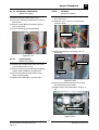
6.2.8 Water Solenoid
6.2.10 Water control microswitch
1) Remove left front panel (refer 6.1.2)
1) Remove left front panel and control panel
(refer 6.1.1 and 6.1.2)
2) Place screwdriver between water valve and
solenoid and lever solenoid away from valve.
6
2) Remove gas control valve cover panel (refer
6.2.6).
3) Remove wires and reassemble with new
solenoid in reverse order.
3) Remove two screws securing microswitch and
disconnect wiring.
Solenoid
Two screws
Microswitch
Water valve
Figure 6.2.10
Figure 6.2.8
6.2.9 Water Solenoid Cleaning
4) Replace switch and reassemble in reverse
order.
1) Remove left front panel (refer 6.1.2).
6.2.11 Indicators
2) Isolate unit from water supply.
1) Remove control panel (refer 6.1.1).
3) Remove water supply pipe from water valve
and remove brass fitting (refer 6.2.13)
2) Remove wires from rear of indicator.
3) Push indicator through front panel from behind.
4) Remove the sieve from the valve assembly by
pulling firmly away from the assembly with a
pair of pliers
4) Replace and reassemble in reverse order.
Figure 6.2.11
Figure 6.2.9
4) Clean the sieve, removing all dirt and grime.
5) Replace the sieve and reconnect the
water supply.
19
Blue Seal Evolution Series Electric Bratt Pans
Revision 1/
© Moffat Ltd, January 2007
6
Service Procedures
6.2.12
Lid Hinge Springs
9) Generously grease the new springs.
10) Insert new springs in, noting that the spring
with the left-hand helix should be inserted in
the right-hand side, and the spring with the
right-hand helix should be inserted in the lefthand side.
1) Using a 3mm Allen key loosen grub screw in
spring hinge tensioner barrel.
2) Take strain off grub screw by turning end
boss, (19mm spanner) on spring hinge
against spring tension (clockwise for RHS,
anticlockwise for LHS)
3) While holding tension on spring remove grub
screw from tensioner barrel with spanner.
4) Place the Allan key into the aligned holes of
the tensioner barrel and end boss, to support
the spring tension.
Right spring
Allan key
Left spring
Figure 6.2.12c
11) Refit end boss and re-tension by reversing the
dismantling procedure (clockwise for RHS,
anticlockwise for LHS).
NOTE: Correct tension has been achieved when
the end boss has been turned half a turn.
6.2.13
Figure 6.2.12a
Hand
Wheel
(Manual Lift Models)
Handle
5) Reposition spanner, take tension off Allan key
and remove Allan key.
1) Prise off the hand-wheel cap and remove the
centre nut and remove the hand-wheel.
6) Allow the end boss to rotate until the next
hole in the end boss lines up with grub screw
hole and replace the Allan key.
2) Undo bolt at back of wheel (using Allan Key)
securing handle to wheel.
7) Repeat steps 5 and 6 until all tension is off
spring.
Bolt
8) Remove the end boss and spring from spring
tensioner barrel.
Tensioner barrel
End boss
Figure 6.2.13
3) Remove handle, replace, and reassemble in
reverse order.
Figure 6.2.12b
20
Blue Seal Evolution Series Electric Bratt Pans
Revision 1/
© Moffat Ltd, January 2007
Service Procedures
6.2.14 Push Button Switch Block
(Electric lift models)
6.2.16
6
Lift Motor
(Electric lift models)
1) Remove left frontr panel (refer 6.1.2).
1) Remove left and right front panels (refer
6.1.2 and 6.1.3)
2) Undo screw securing contact block to rear of
push button.
2) Disconnect four wires to lift motor from
connector block.
3) Remove contact block and transfer wires to
new contact bock.
4) Fit new contact block and reassemble.
Connector block
Figure 6.2.16a
3) Remove through bolt connecting motor to
lead screw.
Figure 6.2.14
6.2.15
Lift motor
Control Button
(Electric lift models)
Through bolt
1) Remove both contact blocks from rear of the
control button (refer 6.2.14).
2) Remove base from push button by unclipping,
using a small screwdriver or similar tool.
Lead screw
3) Undo nut securing the push button to the
switch mounting plate.
4) Replace and reassemble in reverse order.
Figure 6.2.16b
4) Remove three bolts securing motor to bratt
pan frame and remove motor.
5) Replace motor and reassemble in reverse order.
Motor mounting bolts
Figure 6.2.17
21
Blue Seal Evolution Series Electric Bratt Pans
Revision 1/
© Moffat Ltd, January 2007
6
Service Procedures
6.3 Adjustment
6.3.3 Water control microswitch
6.3.1 Pan microswitch adjustment
(Manual lift models)
1) Remove left front and control panels (refer
6.1.1 and 6.1.2).
1) Remove front control panel and left front
panel (refer 6.1.1 and 6.1.2).
2) Remove gas valve cover panel (refer 6.4.4)
3) Bend lever on microswitch so that the switch
clicks on when the water control is turned to
the on position.
2) Bend lever on microswitch so that the switch
clicks on when the pan is completely down in
the cooking position.
4) Replace all covers.
3) Replace front panels.
Water control
Microswitch
Microswitch
Figure 6.3.2
Figure 6.3.1
6.3.2 Pan microswitch adjustment
(Electric lift models)
1) Remove front control panel and left front
panel (refer 6.1.1 and 6.1.2).
2) Bend lever on rear microswitch so that the
switch clicks on when the pan is completely
down in the cooking position.
4) Bend lever on front microswitch so that the
switch clicks on when the pan is completely
up in the lifted position.
Microswitches
Figure 6.3.2
5) Replace front panels.
22
Blue Seal Evolution Series Electric Bratt Pans
Revision 1/
© Moffat Ltd, January 2007
Service Procedures
6
6.3.4 Tensioning the lid springs
1) Using a 3mm Allan key loosen grub screw in
spring hinge tensioner barrel.
2) Take strain off grub screw by turning end
boss, (19mm spanner) on hinge agaist spring
tension (clockwise for RHS, anticlockwise for
LHS).
3) While holding tension on spring remove grub
screw from tensioner barrel.
4) Place the Allan key in the aligned holes of the
tensioner barrel and end boss to support the
spring tension.
Allan key
Figure 6.3.3a
5) Reposition spanner, take tension off Allan key
and remove Allan key.
6) Increase tension on spring by turning end
boss (clockwise for RHS and anticlockwise for
LHS) until the next hole in the end boss lines
up with the grub screw hole in the tensioner
barrel.
Tensioner barrel
End boss
Figure 6.3.3b
7) Replace grub screw and repeat with other
side.
8) Check lid tension - if correct the lid should
hold in the vertical position when raised.
23
Blue Seal Evolution Series Electric Bratt Pans
Revision 1/
© Moffat Ltd, January 2007
7
Accessories
24
Blue Seal Evolution Series Electric Bratt Pans
Revision 1/
© Moffat Ltd, January 2007
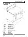
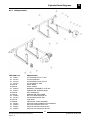
Exploded Parts Diagrams
8.1
8
Electric Bratt Pans
8.1.1 Main Assembly
ITEM PART NO
1 227706
2 227705
3 227850
4 227852
5 228259
6 228669
7 227960
8 227576
227580
9 228848
10 228929
11 227382
12 227963
13 228824
14 228922
15 228939
16 228844
DESCRIPTION
FRYER SIDE PANEL LH
FRYER SIDE PANEL RH
LEG 150mm (FLUSH STUD)
LEG PLATE
WATER SPOUT TUBE
SPLASHBACK BLUESEAL
BADGE BLUESEAL
PAN FASCIA BLUESEAL
FRONT TRIM BLUESEAL
FRONT COVER RH
BOTTOM SILL WA
KNOB BLUESEAL 8mm WATER
NEON ORANGE
KNOB BLUESEAL 8mm 1-10
NEON CLEAR
CONTROL PANEL
FRONT COVER LH
25
Blue Seal Evolution Series Electric Bratt Pans
Revision 1/
© Moffat Ltd, January 2007
8
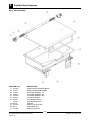
Exploded Parts Diagrams
8.1.2 Main Assembly
ITEM PART NO
17 227520
18 227521
19 227833
20 228814
21 227832
22 227672
23 227841
227847
24 227478
25 227738
26 227741
27 227736
DESCRIPTION
HINGE OUTER TENSION BOSS
HINGE TENSIONER BARREL
LID HINGE SPRING - LH
LID HINGE BARREL WA
LID HINGE SPRING - RH
LID WA BLUESEAL
LID HANDLE 650mm
LID HANDLE 830mm
PAN WA
HINGE PLATE RH WA
PAN HINGE PIN
HINGE PLATE WA
26
Blue Seal Evolution Series Electric Bratt Pans
Revision 1/
© Moffat Ltd, January 2007
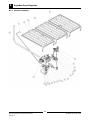
Exploded Parts Diagrams
8
8.1.3 Lifting Assembly
ITEM PART NO
28 228315
29 227722
30 227734
31 227731
32 227739
33 228120
34 020043
35 228117
36 044400
37 228123
38 044066
39 227740
40 227730
41 228906
42 227857
43 020393
44 020394
45 020395
DESCRIPTION
LIFTING BAR PIVOT LH WA
LIFTING ARM WA
LIFTING BAR PIVOT RH WA
LIFTING BAR CLAMP
PIVOT BUSH
LEAD SCREW
BEARING "ASSEMBLY" UCFL204
HANDWHEEL SPACER BUSH
KEY WOODRUFF
HANDWHEEL MACHINED
NUT M16 HEX MACHINE ZP
LIFTING BAR HINGE PIN
LINK ARM
UNIVERSAL JOINT WORKED
ELEC MOTOR & REDUCTION GEARBOX
SWITCH CONTROL BUTTON
SWITCH CONTACT BLOCK N/O
SWITCH AUX CONTACT BLOCK
27
Blue Seal Evolution Series Electric Bratt Pans
Revision 1/
© Moffat Ltd, January 2007
8
Exploded Parts Diagrams
8.1.4 Electrical Assembly
28
Blue Seal Evolution Series Electric Bratt Pans
Revision 1/
© Moffat Ltd, January 2007
Exploded Parts Diagrams
ITEM PART NO
46 227897
47 228623
48 229084
229085
49 229090
50 229091
51 229089
52 011005
53 228874
54 227916
55 003004
56 229355
57 024774
58 013977
59 228948
60 227915
61 015966
62 020062
63 025400
64 025713
65 020851
66 025714
67 024802
68 228933
69 025715
70 020995
8
DESCRIPTION
WATER OUTLET TUBE
PUSH ROD MICROSWITCH
ELEMENT 4000W 240V (900mm WIDE)
ELEMENT 4000W 240V (1200mm WIDE)
ELEMENT RETAINING PLATE LH
ELEMENT RETAINING PLATE CENTRE
ELEMENT RETAINING PLATE RH
BALL CATCH ASSY
WATER SHAFT WA
WATER VALVE LINK ARM
MICROSWITCH
SELECTOR SWITCH KIT
THERMOSTAT 50-320 C
MICROSWITCH INSULATOR
CLEVIS 6mm
WATER VALVE LEVER
CONTACTOR 100C09VA10
WATER VALVE HMC 454x15 CIRCOLA
OVERTEMP THERMOSTAT 360C
TERMINAL BLOCK 10mm GREEN
WATER SOLENOID
TERMINAL BLOCK 10mm GREY
DOOR MICROSWITCH E32/G32
BASIN CONNECTOR 300mm ELBOW
TERMINAL BLOCK 10mm RED
END ANCHOR
29
Blue Seal Evolution Series Electric Bratt Pans
Revision 1/
© Moffat Ltd, January 2007
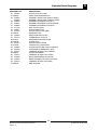
Revision 1/
Blue Seal Evolution Series Electric Bratt Pans
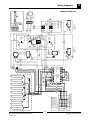
= OPEN SIDE THIS WAY
3 x 025715 TERMINAL BLOCK 10mm RED
1 x 025714 TERMINAL BLOCK 10mm GREY
1 x 025713 TERMINAL BLOCK 10mm GREEN
GND
N
L1
L2
L3
SUPPLY BOX
021224 TERMINAL MARKING GND
021227 TERMINAL MARKING L3
021226 TERMINAL MARKING L2
021225 TERMINAL MARKING L1
021228 TERMINAL MARKING N
PAN
3
3
22
4
1
3
3
1
3
1
3
23
13
15
2
1
5
4
5
8
13
A2
4
6
2
2
14
2
19
C09 CONTACTOR
015966
SAFETY
3
A1
EARTH
STUD
20
2
1
5
22
13
A2
12
4
6
14
24
21
C09 CONTACTOR
015966
HEAT
3
A1
23
EARTH
STUD
15
16
6
14
6
5
7
NO
NC
18
16
NC
NO
COM
OVERTEMP
025400
19
COM
WATER
MICROSWITCH
003004
WATER
SOLENOID
020851
10
9
NEON
AMBER
227963
10
P1
P2
1
1
2
NEON
GREEN
227962
8
SWITCH
228999
2
CONTROL PANEL
17
E
THERMOSTAT
024774
21
24
9
12
18
11
9
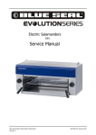
Wiring Diagrams
E580-8 & E580-12
YE R G K C OL B L A NI MRET 417520
30
© Moffat Ltd, January 2007
Revision 1/
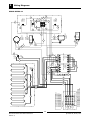
Blue Seal Evolution Series Electric Bratt Pans
N
= OPEN SIDE THIS WAY
3 x 025715 TERMINAL BLOCK 10mm RED
1 x 025714 TERMINAL BLOCK 10mm GREY
1 x 025713 TERMINAL BLOCK 10mm GREEN
GND
1
1
3
25
21
22
2
1
5
5
13
A2
27
4
6
2
2
14
C09 CONTACTOR
015966
SAFETY
3
A1
9
2
28
2
1
5
13
A2
29
4
6
015966
HEAT
14
C09 CONTACTOR
3
A1
13
7
20
17
7
5
NO
NC
8
26
23
COM
PAN DOWN
MICROSWITCH
024802
NC
NO
OVERTEMP
025400
27
COM
WATER
MICROSWITCH
003004
WATER
SOLENOID
020851
11
10
11
1
2
NEON
GREEN
227962
9
SWITCH
228999
2
6
CONTROL PANEL
24
P1
P2
1
10
NEON
AMBER
227963
THERMOSTAT
024774
29
13
26
12
17
25
34
E
16
19
32
15
PAN UP
MICROSWITCH
024802
NC
NO
18
COM
LH COVER PANEL
14
WHITE
BLUE
RED
GREEN
14
TERMINAL BLOCK
025950
GREEN
O/ N
L1
1
3
3
31
EARTH
STUD
23
E
W2
BLUE
U2
RED
V2
WHITE
O/ N
L2
30
3
32
22
33
C/ N
L3
3
4
30
33
35
Motor
MOTOR TERMINATION BOX, WIRING DETAIL
C/ N
SUPPLY BOX
021224 TERMINAL MARKING GND
021227 TERMINAL MARKING L3
021226 TERMINAL MARKING L2
021225 TERMINAL MARKING L1
021228 TERMINAL MARKING N
PAN
3
4
31
EARTH
STUD
34
Wiring Diagrams
9
E580-8E & E580-12E
Y E R G K C OL B L A NI MRET
4 1 7 52 0
31
© Moffat Ltd, January 2007
10
Service Contacts
Utensils Direct
0845 873 6600
www.utensilsdirect.co.uk
32
Blue Seal Evolution Series Electric Bratt Pans
Revision 1/