1
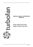
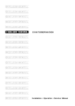
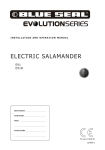
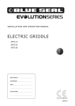
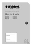
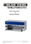
INSTALLATION / OPERATION
MANUAL
E35 CONVECTION OVEN
232109-4
MANUFACTURED BY
Moffat Limited
PO Box 10001
Christchurch
New Zealand
Ph:
(03) 389 1007
Fax:
(03) 389 1276
WORLD-WIDE BRANCHES
UNITED KINGDOM
Blue Seal
67 Gravelly Business Park
Gravelly Park
Birmingham
West Midlands
B24 8TQ
Ph:
(121) 327 5575
Fax:
(121) 327 9711
UNITED STATES
Moffat Inc
3765 Champion Blvd
Winston-Salem
North Carolina 27115
Ph:
(336) 661 0257
Fax:
(336) 661 9546
CANADA
Serve Canada
22 Ashwarren Road
Downview
Ontario M3J1Z5
Toll Free:800 263 1455
Ph:
(416) 631 0601
Fax:
(416) 631 0315
[email protected]
www.servecanada.com
www.moffat.com
NEW ZEALAND
Christchurch
Moffat Limited
PO Box 10-001
16 Osborne Street
Christchurch
Ph:
(03) 389 1007
Fax:
(03) 389 1276
Auckland
Moffat Limited
4 Waipuna Road
Mt Wellington
Auckland
Ph:
(09) 574 3150
Fax: (09) 574 3159
AUSTRALIA
Victoria
Moffat Pty Limited
740 Springvale Road
Mulgrave, Melbourne
Victoria 3171
Ph:
(03) 9518 3888
Fax:
(03) 9518 3838
New South Wales
Moffat Pty Limited
3/142 James Ruse Drive, Rose Hill
PO Box 913, Smithfield
Sydney, N.S.W. 2142
Ph:
(02) 8833 4111
Fax: (02) 8833 4133
Western Australia
Moffat Pty Limited
67 Howe Street
Osbourne Park
WA 6017
Ph:
(08) 9202 6820
Fax:
(08) 9202 6836
Queensland
Moffat Pty Limited
30 Prosperity Place
Geebung, Brisbane
Queensland 4034
Ph:
(07) 3630 8600
Fax
(07) 3630 8623
The reproduction or copying of any part of this manual by any means whatsoever is strictly forbidden unless authorized previously in
writing by the manufacturer.
In line with policy to continually develop and improve its products, Moffat Ltd. reserves the right to change the specifications and
design without prior notice.
© Copyright Moffat Ltd. January 2009
Contents
Introduction ........................................................................................................ 2
Installation .......................................................................................................... 3
Installation Requirements
Before Connection to Power Supply
Location
Bench Mounting
Floor Mounting
Stand Mounting
Electrical Connection
Water Connection
Before Use
Specifications .................................................................................................... 5
Operation............................................................................................................ 6
Description of Controls
Baking
Door Handle
Oven Side Racks
Removal of Side Racks
Replacement of Side Racks
Cleaning............................................................................................................ 10
Cleaning Guidelines
Exterior
Interior
Oven Racks
Oven Side Racks
Oven Door Glass
Oven Door Seal
Faultfinding ...................................................................................................... 11
Circuit Schematics........................................................................................... 12
Replacement Parts List ................................................................................... 15
Date Purchased................................................................. Serial No ..........................................................
Dealer ............................................................................................................................................................
Service Agent ................................................................................................................................................
1
Introduction
We are confident that you will be delighted with your TURBOFAN OVEN, and it will become a most valued
appliance in your commercial kitchen.
A new oven can seem very complex and confusing at first glance. To ensure you receive the utmost
benefit from your new Turbofan, there are two important things you can do.
Firstly
Please read the instruction book carefully and follow the directions given. The time taken will be well
spent.
Secondly
If you are unsure of any aspect of the installation, instructions or performance of your oven, contact your
E35 dealer promptly. In many cases a phone call could answer your question.
2
Installation
Installation Requirements
It is most important that this oven is installed correctly and that operation is correct
before use.
Installation shall comply with local electrical, health and safety requirements.
This equipment is to be installed to comply with the Federal, State or local plumbing codes
having jurisdiction.
Before Connection to Power Supply
•
Remove all packing.
•
Check equipment and parts for damage. Report any damage immediately to the carrier and
distributor.
•
Remove protective plastic coating from the side panels.
•
Check that the following parts have been supplied with your oven:
1 x Water inlet elbow (c/w washer).
•
Report any deficiencies to the distributor who supplied the oven.
•
Fit the feet to the oven.
•
Check that the available power supply is correct to that shown on the rating plate located on the
right-hand side panel.
Model
Electrical Rating
E35-xx-251
230-240 V a.c., 50 Hz, 1P+N+E, 12.5 kW @ 240 V
E35-xx-P251
208-220 V a.c., 50 Hz, 1P+N+E, 12.5 kW @ 220 V
E35-xx-P253
208-220 V a.c., 50 Hz, 3P+E, 12.5 kW @ 220 V
E35-xx-P261
208-220 V a.c., 60 Hz, 1P+N+E, 12.5 kW @ 220 V
E35-xx-P263
208-220 V a.c., 60 Hz, 3P+E, 12.5 kW @ 220 V
E35-xx-T251
230-240 V a.c., 50 Hz, 1P+N+E, 12.5 kW @ 240 V
E35-xx-T253
230-240 V a.c., 50 Hz, 3P+E, 12.5 kW @ 240 V
E35-xx-T261
230-240 V a.c., 60 Hz, 1P+N+E, 12.5 kW @ 240 V
E35-xx-T263
230-240 V a.c., 60 Hz, 3P+E, 12.5 kW @ 240 V
E35-xx-353
380 V a.c., 50 Hz, 3P+N+E, 12.5 kW @ 380 V
E35-xx-363
380 V a.c., 60 Hz, 3P+N+E, 12.5 kW @ 380 V
E35-xx-453
400-415 V a.c., 50 Hz, 3P+N+E, 12.5 kW @ 415 V
E35-xx-463
400-415 V a.c., 60 Hz, 3P+N+E, 12.5 kW @ 415 V
E358-xx-453
400-415 V a.c., 50 Hz, 3P+N+E, 8.0 kW @ 415 V
Location
•
To ensure correct ventilation for the motor and controls the following minimum installation
clearances are to be adhered to:
•
Position the oven in its working position.
Rear
Left-hand side
Right-hand side
0“ / 0 mm
0” / 0 mm
3” / 75 mm
(Fixed installations require at least 500mm (20”) clearance at
the right hand side for service accessibility).
3
Installation
•
Use a spirit level to ensure oven is level from side to side and front to back. (If this is not carried
out, uneven cooking could occur). The feet / legs used with bench/floor mounting or provided with
stands are adjustable and will require adjusting in levelling the unit.
•
The unit should be positioned such that the operating panel and oven shelves are easily reachable
for loading and unloading.
Important:
THE VENT LOCATED ON THE OVEN TOP MUST NEVER BE OBSTRUCTED.
Bench Mounting
•
For bench mounted applications the oven must be fitted with 100 mm / 4 inch feet.
C AUTIO N :
To reduce the risk of fire, the appliance is to be installed over a non-combustible surface only.
Such surface shall extend not less than 12 inches (300 mm) beyond the appliance on all sides.
Floor Mounting
•
For floor mounted applications the oven must be fitted with 150mm / 6inch legs.
NOTE: Four 100 mm / 4 inch adjustable or 150 mm / 6 inch legs are available separately from your
E35 dealer as an optional extra.
Stand Mounting
•
Ovens that are to be mounted on stands do not require feet or legs. Refer to instructions for
mounting on stand in instructions supplied with separately ordered stands.
•
Avoid having heat producing equipment such as fryers or steamers adjacent to the right-hand side
of oven.
Electrical Connection
Important:
• FIXED WIRING INSTALLATIONS MUST INCORPORATE AN ALL-POLE DISCONNECTION
SWITCH.
•
•
•
•
Remove side cover panel to allow access to the terminal block and strain relief cable clamp.
The cable can be fitted through the entry grommet and secured from strain by tightening the fitted
strain relief bushing.
Connect cable to the terminals as marked.
Refit cover panel.
THIS APPLIANCE MUST BE EARTHED / GROUNDED.
Water Connection
•
A cold water supply should be fitted to the water inlet (¾” BSP connection) which is located near
the rear of the right hand side of the unit.
•
Alternately, a connection elbow and sealing washer is supplied with this unit for direct connection
of a ½” ID hose, and is recommended for easy installation and service.
•
Connect water supply - Max inlet pressure 80psi / 550kPa.
•
Turn on water supply to check for leaks.
Before Use
•
Operate the oven for about 1 hour at 400°F (200°C) to remove any fumes or odours which may be
present.
4
Specifications
E35 Specifications
345
8"
345
8"
1"
38
1"
62
1"
312
15/16”
E
283
8"
1"
62
3
WATER ENTRY
3
MWS
E
25
8"
MWS
ELECTRICAL ENTRY
17
8"
1"
264
SIDE
FRONT
MWS
3
E
PLAN
247
8"
VENT Ø 76 O.D.
Electrical Connection
Refer to Section 'Before Connecting to Power Supply' on Page 3.
Cold Water Connection
¾” B.S.P. or 1/2 ID hose (550kPa / 80psi maximum pressure).
5
Operation
Description of Controls
35
Vent
Vent closed with switch in the vertical position.
Vent open with switch in the horizontal position.
°C
60
80
100
280
Thermostat
120
Temperature range 100 - 550°F (60-280°C).
Indicator illuminates when the elements are cycling
ON to maintain set temperature.
220
200
140
180
160
Bake Timer
1 Hour bake timer.
(Indicator illuminates when “time up” (0) reached,
and buzzer sounds).
Steam Switch
Push steam switch to activate steam into the oven
chamber. Release switch to stop steam.
Fan Speed
Full fan speed in the vertical (HI) position.
Half fan speed in the horizontal (LO) position.
Power
l
Turn to switch power on or off (on horizontal, off
vertical) (indicator illuminates when power is on).
6
Operation
Baking
1. Turn Power 'On'
The indicator light will illuminate whenever the switch is in the “I” (On) position (the oven
lights will also illuminate).
The oven fan will start after 10 seconds with the door closed. The fan delay will repeat whenever the door is closed after opening.
The oven fan will change rotation direction every 90 seconds.
2. Fan Speed
The oven fan can either be operated at “HI” fan speed or “LO” speed by rotating the knob.
This maybe done before or during a cooking cycle.
For most applications the HI fan speed provides best results. For delicate baked products or
roasting the LO fan speed may be more suitable.
3. Oven Vent
The oven vent can be opened or closed at any stage during a cooking cycle in the oven.
For best steam results on baked product always ensure the oven vent is closed.
The oven vent combines an over pressure feature that allows the vent to open automatically
when required for periods when steam injection is used, to relieve excess pressure.
4. Set Thermostat to Desired Cooking Temperature
The thermostat indicator light will illuminate when ever the elements are cycled on to maintain
set temperature.
5. Load Oven
Once the oven is up to temperature, open the door and load the oven with product. Avoid
delays in loading the oven with the door open as this will delay oven temperature recovery.
The ovens fan will stop when the door is opened. The fan will start 10 seconds after the door
is closed.
6. Steam
When steam is required press the steam button. Steam will be injected into the oven
chamber for as long as the steam button is held pressed.
7. Set Timer to Desired Time.
To set timer, turn knob clockwise to the required time. At any stage, the time can be adjusted
in either direction.
For settings less than 10min, first set to greater setting, then turn down to required time
period.
This 60 minute timer is completely independent of the oven control.
7
Operation
Baking
8. Time Up
When the timer reaches 0 minutes the buzzer will sound, and the indicator illuminates.
To cancel the buzzer turn the timer to the off position.
9. Unload Oven
Open the door and unload the oven .
The oven fan will stop when the door is opened.
Door Handle
Standard Door Catch Operation
A.
To open the oven door, rotate the handle either clockwise or anti-clockwise to the 'Open'
position to unlatch the door and pull the door open with the door handle.
B.
To close the door, push the door firmly closed and the door will lock in the closed position.
(there is no need to turn the handle to the closed position as the door self-latches in the
closed position and the handle will self-centre to the 'Closed' position.
Open
Closed
Position
8
Open
Operation
Side Racks
16 inch tray
locator
1. The side racks can be fitted in one of two
positions, in order to take 16 or 18 inch
trays.
2. To position racks for 16 inch trays, use the
holes at the rear of the rack.
3. Alternatively for 18 inch trays, use the holes
nearest the centre of the oven.
18 inch tray
locator
Removal of Side Racks
1.
Lift the side rack off the bottom locating
pins.
2.
Move the bottom of the side rack toward
the centre of the oven.
3.
Lower side rack to clear top locating pins,
and remove.
3
Replacement of Side Racks
1.
Insert rack into the oven, placing
appropriate holes over the top locating
pins.
2.
Lift the side rack over the bottom locating
pins.
3.
Lower side rack with the appropriate holes
over the bottom locating pins.
1
2
9
Cleaning
Cleaning Guidelines
C AUTIO N :
ALWAYS TURN OFF THE POWER SUPPLY BEFORE CLEANING.
THIS UNIT IS NOT WATER PROOF.
DO NOT USE WATER JET SPRAY TO CLEAN INTERIOR OR EXTERIOR OF THIS UNIT.
Exterior
Clean with a good quality stainless steel cleaning compound. Harsh abrasive cleaners may damage
the surface.
Interior
Ensure that the oven chamber is cool. Do not use wire brushes, steel wool or other abrasive materials.
Clean the oven regularly with a good quality oven cleaner. Take care not to damage the fan or oven
lights.
Oven Racks
To remove, follow instructions given in Operation section.
Side Racks
To remove, follow instructions given in Operation section.
TOP
Oven Door Glass
LOCKED
Outer Surfaces
Clean with conventional glass cleaners
UN-LOCKED
Inner Surfaces
To clean between the inner and outer door
glasses, firstly ensure the door is locked shut
(refer to page 9). With a screwdriver, coin, or
other suitable device, ¼ turn the outer glass
locks to release the outer glass and allow it to
be hinged open for cleaning access (refer
diagram for correct procedure).
UN-LOCKED
LOCKED
Important:
BOTTOM
Always ensure outer glass is hinged closed and
locked into position before opening the oven door.
Oven Door Seal
To remove, pull out the seal starting at each
corner.
The seal may be washed in the sink, but take
care not to cut or damage it.
To replace, fit the seal in at the corners first,
then push in the rest of the seal.
10
Fault Finding
CAUTION:
This appliance is;
•
For professional use and is to be used by qualified persons only.
•
Only authorised service persons are to carry out installation, and servicing
operations.
•
Components having adjustments protected (e.g. paint sealed) by the
manufacturer should not be adjusted by the user / operator.
This section provides an easy reference guide to the more common problems that may occur during the
operation of your equipment. The fault finding guide in this section is intended to help you correct, or at
least accurately diagnose problems with your equipment.
Although this section covers the most common problems reported, you may encounter a problem not
covered in this section. In such instances, please contact your local authorised service agent who will
make every effort to help you identify and resolve the problem. Please note that the service agent will
require the following information:• Model code and Serial Number of the appliance. (both can be found on the Rating Plate
Fault
Possible Cause
Remedy
The oven does not operate / start. The mains isolating switch on the Turn 'On'.
wall, circuit breaker or fuses are
'Off' at the power board.
The power switch on the oven is Depress switch. Switch will
'Off'.
illuminate.
Overtemp
tripped.
safety
thermostat Reset (Button located at bottom
RH side of RH side panel). If fault
re-occurs call for service.
Oven light illuminating but fan not Oven door not closed properly.
Close oven door properly.
working and oven not heating.
Door switch or door catch broken. Call for service.
Bake timer does not time down.
Bake timer not set correctly.
For settings less than 10 minutes,
first set to greater setting then turn
back to desired setting.
Oven light not illuminating.
Blown bulb.
Replace bulb.
No water injection / steam.
Water not turned 'On'.
Turn water 'On' at water supply.
11
Circuit Schematic
208V-220V, 3P+E
230-240V, 3P+E
12
Circuit Schematic
208-220V, 1P+N+E
230-240V, 1P+N+E
13
Circuit Schematic
380V, 3P+N+E
400-415V, 3P+N+E
14
Replacement Part List
Replacement Part List
Control Panel
020849
020985
011760
232411
231792
020822
231764
020883K
020823
Neon Indicator Light.
Thermostat Potentiometer.
Timer - (60 Minute).
Steam Switch Assembly.
Selector Switch (Fan Speed).
Selector Switch (Power).
Solid State Thermostat.
Thermostat Probe.
Control Panel Knobs.
Gear Plate
231740
231739
231741
231742
231743
024567
231748
232410
232409
232408
232407
232108
231814
021352
021354
025400
021156
Heating Contactor
E35-xx-x253 / 263 (3P+E) Models Only.
Heating Contactor
1P+N+E & 3P+N+E Models.
Motor Contactor.
Motor Contactor
1 Phase Models Only.
Contactor Interlock
3 Phase Models Only.
Timer - Fan Direction.
Timer - On Delay
1 Phase Models Only.
Shunt Trip.
Circuit Breaker - 40A
E35-xx-x253 / 263 (3P+E) Models Only.
Circuit Breaker - 25A.
1P+N+E & 3P+N+E Models.
Circuit Breaker - 6A.
Lamp Holder Complete
(G9 Halogen).
Light Bulb G9.
25W 230V - (G9 Halogen).
Oven Lamp Glass.
Lamp Gasket.
Over Temperature Thermostat.
Cooling Fan.
232551
231553
231554
Capacitor 10mF,
Capacitor 20mF,
Capacitor 30mF,
50Hz, 1 Phase Models Only.
232552
232555
Capacitor 12mF,
Capacitor 35mF,
60Hz, 1 Phase Models Only.
011794
Buzzer.
Motor & Elements
020886K
020885K
020745K
025396
020896
020762
020763
022259
020774
Motor Kit - 208-240V 60Hz.
Motor Kit - 208-240V 50Hz.
Motor Kit - 380-415V.
Fan.
Motor Shaft Seal.
Element - 230 - 240V, 2000W.
Element - 208 - 220V, 2000W.
Element - 230 - 240V, 1250W, - (E358, 8kW Models Only).
Microswitch.
Steam System
020851
020853
020819
020824
Water Solenoid Valve.
Spray Adaptor Body.
Vent Over-Pressure Spring.
Vent Gasket.
15
Replacement Part List
Replacement Part List (continued)
Door
231438
231804
231803
232364
231801
230745
230741
230742
231494
232134
Door Seal.
Single Step Locking Dog.
Door Inner Glass.
Door Glass Outer Spring.
Door Inner Glass Buffer.
Hinge Bush.
Hinge Mounting Plate Top.
Hinge Mounting Plate Bottom.
Door Handle.
Door Outer Glass Assembly.
Racks
020809
020810
020811
020812
015168
020993
Side Rack L / Hand WA (E35-26”).
Side Rack R / Hand WA (E35-26”).
Side Rack L / Hand WA (E35-30”).
Side Rack R / Hand WA (E35-30”).
Oven Rack (E35-26”).
Oven Rack (E35-30”).
Optional Extras
025916
025917
026127
026128
025089
025090
Rack Runner 4 Tray LH WA (E35-26”).
Rack Runner 4 Tray RH WA (E35-26”).
Rack Runner 5 Tray LH WA (E35-26”).
Rack Runner 5 Tray RH WA (E35-26”).
Rack Runner 8 Tray LH WA (E35-26”).
Rack Runner 8 Tray RH WA (E35-26”).
023118
023119
026590
026591
Side Rack L / Hand WA 8 Tray (E35-30”).
Side Rack R / Hand WA 8 Tray (E35-30”).
Rack Runner 4 Tray L / Hand WA (E35-30”).
Rack Runner 4 Tray R / Hand WA (E35-30”).
021236
021237
021348
230578
Double Stack Kit (E35-26”).
Double Stack Kit (E35-30”).
Adjustable Legs 4”.
Leg Assy 150mm ST/ST.
16